Embed Size (px)
Citation preview
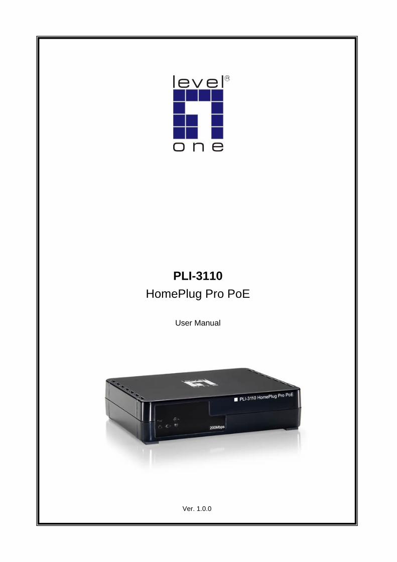
Ver. 1.0.0
PLI-3110 HomePlug Pro PoE
User Manual

1
Safety FCC This equipment has been tested and found to comply with Part 15 Class B of the FCC Rules. Operation is subject to the following two conditions:
(1) This device may not cause harmful interference
(2) This device must accept any interference received, including interference that may cause undesired operation.
CE This equipment is in compliance with the requirements of the following regulations: CE Mark, 89/336/EEC
RoHS
This product is RoHS compliant.
2
Table of Contents
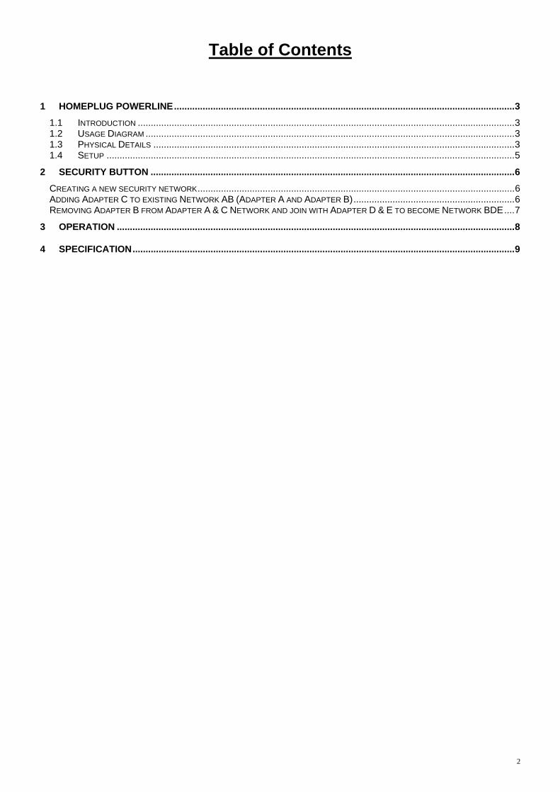
1 HOMEPLUG POWERLINE...................................................................................................................................3 1.1 INTRODUCTION .................................................................................................................................................3 1.2 USAGE DIAGRAM ..............................................................................................................................................3 1.3 PHYSICAL DETAILS ...........................................................................................................................................3 1.4 SETUP .............................................................................................................................................................5
2 SECURITY BUTTON ............................................................................................................................................6 CREATING A NEW SECURITY NETWORK..........................................................................................................................6 ADDING ADAPTER C TO EXISTING NETWORK AB (ADAPTER A AND ADAPTER B)..............................................................6 REMOVING ADAPTER B FROM ADAPTER A & C NETWORK AND JOIN WITH ADAPTER D & E TO BECOME NETWORK BDE....7
3 OPERATION .........................................................................................................................................................8
4 SPECIFICATION...................................................................................................................................................9
3
1 HomePlug Powerline
HomePlug Powerline is an excellent solution that can be used to extend your network. In the home or small office
building, use HomePlug Ethernet Bridge Adapters to link multiple locations without the need to run Ethernet cable.
Combined with a broadband DSL/Cable connection, every room with electrical power outlets will have easy access
to high-speed Internet connection.
1.1 Introduction
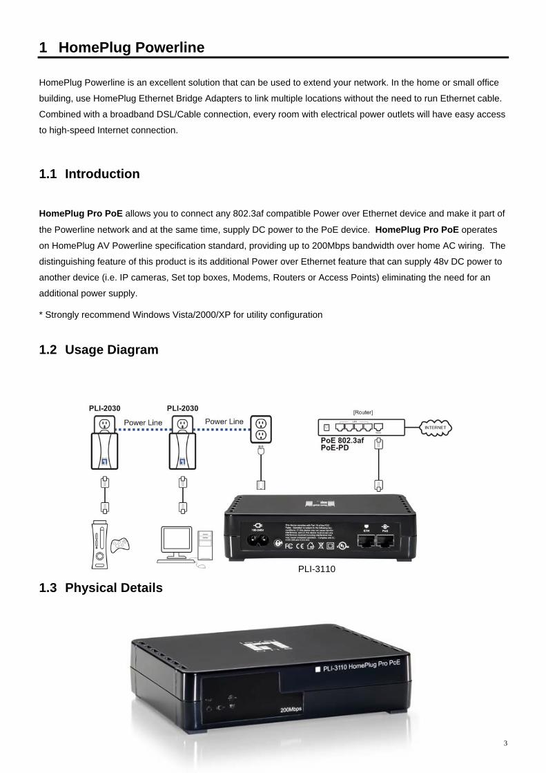
HomePlug Pro PoE allows you to connect any 802.3af compatible Power over Ethernet device and make it part of
the Powerline network and at the same time, supply DC power to the PoE device. HomePlug Pro PoE operates
on HomePlug AV Powerline specification standard, providing up to 200Mbps bandwidth over home AC wiring. The
distinguishing feature of this product is its additional Power over Ethernet feature that can supply 48v DC power to
another device (i.e. IP cameras, Set top boxes, Modems, Routers or Access Points) eliminating the need for an
additional power supply.
* Strongly recommend Windows Vista/2000/XP for utility configuration
1.2 Usage Diagram
PLI-3110
1.3 Physical Details
4
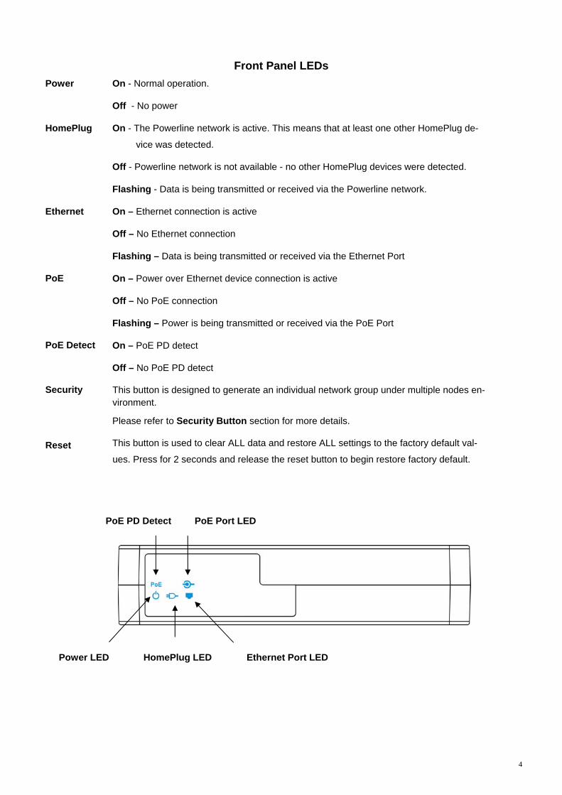
Front Panel LEDs
Power On - Normal operation.
Off - No power
HomePlug On - The Powerline network is active. This means that at least one other HomePlug de-
vice was detected.
Off - Powerline network is not available - no other HomePlug devices were detected.
Flashing - Data is being transmitted or received via the Powerline network.
Ethernet
PoE
PoE Detect
Security
Reset
On – Ethernet connection is active
Off – No Ethernet connection
Flashing – Data is being transmitted or received via the Ethernet Port
On – Power over Ethernet device connection is active
Off – No PoE connection
Flashing – Power is being transmitted or received via the PoE Port
On – PoE PD detect
Off – No PoE PD detect
This button is designed to generate an individual network group under multiple nodes en-vironment.
Please refer to Security Button section for more details.
This button is used to clear ALL data and restore ALL settings to the factory default val-
ues. Press for 2 seconds and release the reset button to begin restore factory default.
Power LED Ethernet Port LED HomePlug LED
PoE Port LED PoE PD Detect

5
Rear Panel The rear panel contains an AC Power Cord Plug (100-240V), a Security Button, a recessed Reset Button, and an
Ethernet Port for 48V-802.3af PoE enabled device.
1.4 Setup Plug and Play Installation for Homes:
HomePlug is plug and play device; user is able to plug and play without any complex configuration and settings.
Please execute the following hardware installation steps 1 to 4.
Installation in homes with Existing HomePlug Network:
1. Connect the HomePlug Pro PoE Ethernet Port to a 802.3af enabled PoE Device.
2. Plug the HomePlug Pro PoE into a power outlet.
3. Wait a few seconds for startup to be completed, and then check the LEDs.
• The Power LED should be ON
• The HomePlug LED will be ON
• The PoE LED should be ON
4. Hardware Installation is now completed, enjoy HomePlug Powerline connectivity. Installation in homes with NO EXISTING HomePlug Network: 1. Make sure that another HomePlug 200M device is connected to your network at the router or directly to a com-
puter. 2. Connect the HomePlug Pro PoE Ethernet Port to a 802.3af enabled PoE Device. 3. Wait a few seconds for startup to be completed, and then check the LEDs.
• The Power LED should be ON
• The HomePlug LED will be ON
• The PoE LED should be ON
4. Hardware Installation is now completed, enjoy HomePlug Powerline connectivity.
Power Port PoE Port Ethernet PortSecurity Button
Reset Button on the side
6
2 Security Button This section describes how to use Security button for configuration in the following situations:
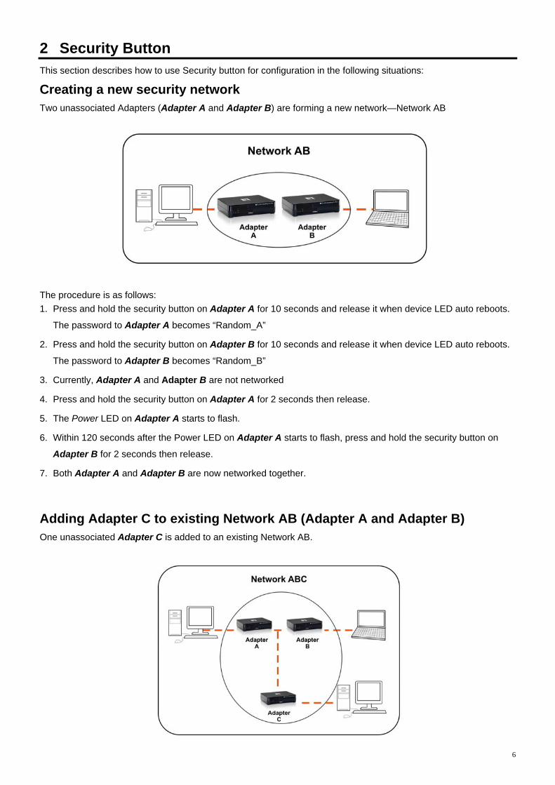
Creating a new security network Two unassociated Adapters (Adapter A and Adapter B) are forming a new network—Network AB
The procedure is as follows: 1. Press and hold the security button on Adapter A for 10 seconds and release it when device LED auto reboots.
The password to Adapter A becomes “Random_A”
2. Press and hold the security button on Adapter B for 10 seconds and release it when device LED auto reboots.
The password to Adapter B becomes “Random_B”
3. Currently, Adapter A and Adapter B are not networked
4. Press and hold the security button on Adapter A for 2 seconds then release.
5. The Power LED on Adapter A starts to flash.
6. Within 120 seconds after the Power LED on Adapter A starts to flash, press and hold the security button on
Adapter B for 2 seconds then release.
7. Both Adapter A and Adapter B are now networked together.
Adding Adapter C to existing Network AB (Adapter A and Adapter B) One unassociated Adapter C is added to an existing Network AB.
7
The procedure is as follows:
8. Press and hold the security button on Adapter C for 10 seconds and release it when device LED auto reboots.
The password to Adapter C becomes “Random_C”
9. Press and hold the security button on Adapter A for 2 seconds. The Power LED on Adapter A starts to flash.
10. Within 120 seconds after the Power LED on Adapter A starts to flash, press and hold the security button on
Adapter C for 2 seconds then release.
11. Adapter A, Adapter B and Adapter C are now networked to each other.
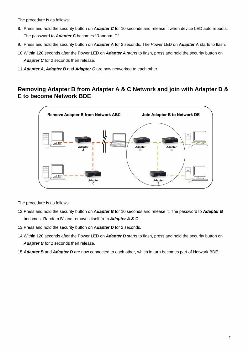
Removing Adapter B from Adapter A & C Network and join with Adapter D & E to become Network BDE
The procedure is as follows:
12. Press and hold the security button on Adapter B for 10 seconds and release it. The password to Adapter B
becomes “Random B” and removes itself from Adapter A & C.
13. Press and hold the security button on Adapter D for 2 seconds.
14. Within 120 seconds after the Power LED on Adapter D starts to flash, press and hold the security button on
Adapter B for 2 seconds then release.
15. Adapter B and Adapter D are now connected to each other, which in turn becomes part of Network BDE.
8
3 Operation
Operation is completely automatic, and no user intervention is required.
If your HomePlug devices have difficulty communicating with each other, check the following:
• Try plugging the unit into an adjacent plug.
• Use a pin and hold the Reset Button down for two seconds on each unit you are trying to connect. The unit
lights should flash. Then units will then connect based off factory settings.
• HomePlug Pro PoE works better when plugged directly into the wall socket. Connecting the HomePlug Pro
PoE into the power strip or surge protectors may degrade the network performance.
9
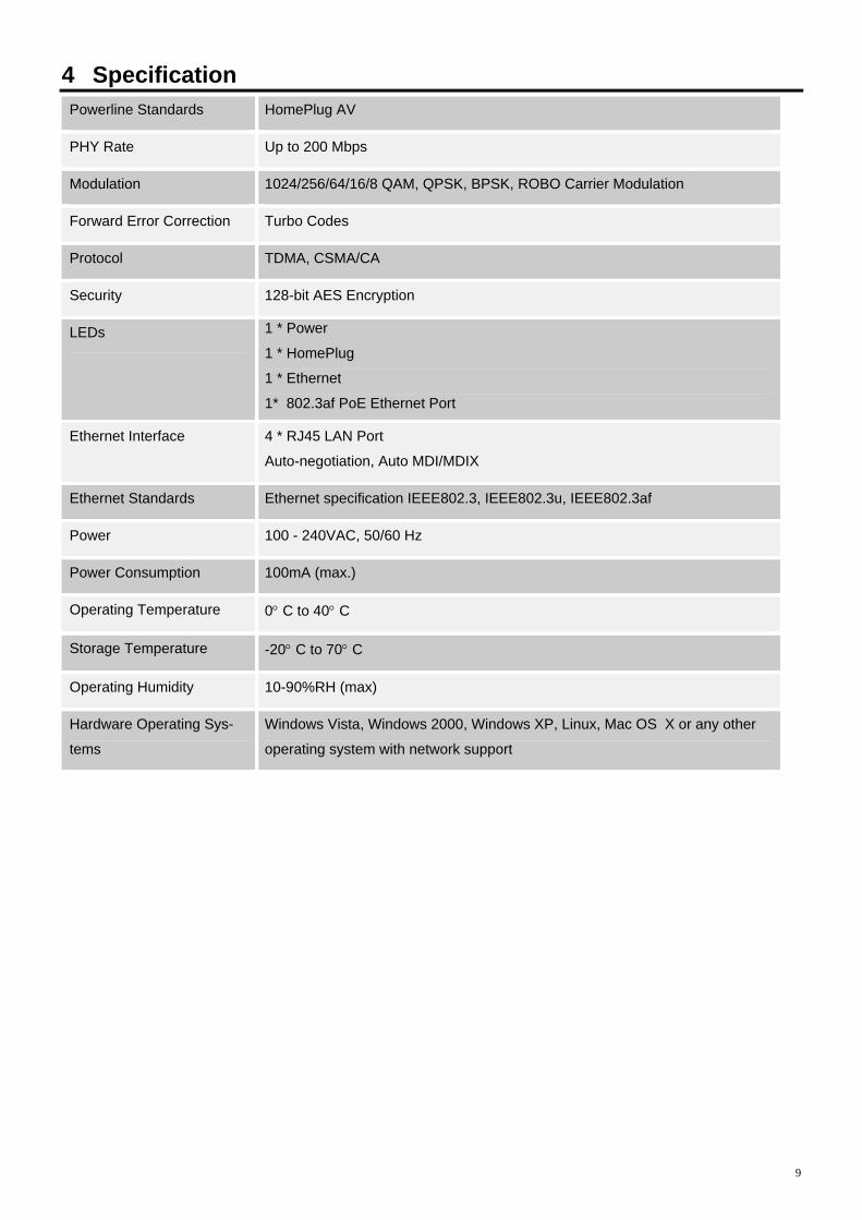
4 Specification Powerline Standards HomePlug AV
PHY Rate Up to 200 Mbps
Modulation 1024/256/64/16/8 QAM, QPSK, BPSK, ROBO Carrier Modulation
Forward Error Correction Turbo Codes
Protocol TDMA, CSMA/CA
Security 128-bit AES Encryption
LEDs 1 * Power
1 * HomePlug
1 * Ethernet
1* 802.3af PoE Ethernet Port
Ethernet Interface 4 * RJ45 LAN Port
Auto-negotiation, Auto MDI/MDIX
Ethernet Standards Ethernet specification IEEE802.3, IEEE802.3u, IEEE802.3af
Power 100 - 240VAC, 50/60 Hz
Power Consumption 100mA (max.)
Operating Temperature 0° C to 40° C
Storage Temperature -20° C to 70° C
Operating Humidity 10-90%RH (max)
Hardware Operating Sys-
tems
Windows Vista, Windows 2000, Windows XP, Linux, Mac OS X or any other
operating system with network support