Embed Size (px)
Citation preview


Outlaw Audio2
Please Read First
CAUTION: To reduce the risk of electric shock, do not remove the cover. No user serviceable parts inside. Refer to qualified personnel.
WARNING: To reduce the risk of fire or electric shock, do not expose this appliance to rain or moisture.
The lightning flash with arrowhead, with in an equilateral triangle, is intended to alert the user to the presence of uninsu lated “dangerous voltage” within the product’s enclosure that may be of sufficient magnitude to constitute a risk of electrical shock to persons.
The exclamation point within an equilateral triangle is intended to alert the user to the presence of important operating maintenance (servicing) instructions in the literature accompanying the appliance.
WARNING: Important Safeguards
¼ Power-Cord Protection Power-supply cords should be routed so that they are not likely to be walked on or pinched by items placed upon or against them, paying particular attention to cords where they enter a plug, or a convenience receptacle, and the point where they exit from the unit.
¼ Outdoor Antenna Grounding If an outside antenna or cable system is connected to the unit, be sure the antenna or cable system is grounded so as to provide some protection against voltage surges and built-up static charges. Article 810 of the National Electrical Code, ANSI/NFPA 70, provides information with regard to proper grounding of the mast and supporting structure, grounding of the lead-in wire to an antenna-discharge unit, size of grounding conductors, location of antenna-discharge unit, connection to grounding electrodes, and requirements for the grounding electrode.
¼ Lightning For added protection for the unit during a lightning storm, or when it is left unattended and unused for long periods of time, unplug it from the wall outlet and disconnect the antenna or cable system. This will prevent damage to the unit due to lightning and power-line surges.
¼ Power Lines An outside antenna system should not be located in the vicinity of overhead power lines or other electric light or power circuits, or where it can fall into such power lines or circuits. When installing an outside antenna system, extreme care should be taken to keep from touching such power lines or circuits as contact with them might be fatal.
¼ Overloading Do not overload wall outlets, extension cords, or integral convenience receptacles as this can result in a risk of fire or electric shock.
¼ Object and Liquid Entry Never push objects of any kind into the unit through openings as they may touch dangerous voltage points or short-out parts that could result in a fire or electric shock. Never spill liquid of any kind on the unit.
¼ Servicing Do not attempt to service the unit yourself as opening or removing covers may expose you to dangerous voltage or other hazards. Refer all servicing to Outlaw Audio.
¼ Damage Requiring Service Unplug the unit from the wall outlet and refer servicing to Outlaw Audio under the following conditions:
» When the power-supply cord or plug is damaged,
» If liquid has been spilled, or objects have fallen into the unit,
» If the unit has been exposed to rain or water,
» If the unit does not operate normally by following the operating instructions. Adjust only those controls that are covered by the operat-ing instructions as an improper adjustment of other controls may result in damage and will often require extensive work by Outlaw Audio to restore the unit to its normal operation,
» If the Model 5000 has been dropped or damaged in any way, the unit should be examined by Outlaw Audio.
¼ Heat The unit should be situated away from heat sources such as radiators, heat registers, stoves, or other units (including amplifiers) that produce heat.
IMPORTANT SAFETY NOTE Before connecting a new component such as the Model 5000 to your audio or home theater system it is always
good practice to make certain that all components are turned off, and preferably unplugged from their AC power source. Many modern electronics products feature automatic turn-on circuits that may be activated during an installation, causing the potential for damage to electronic components and/or speakers. Such damage is not covered by product warranties and Outlaw Audio specifically disclaims responsibility for any such damage.
Precautions
Verify The Line VoltageYour new amplifier has been factory configured for 120 (+/- 3%) volt AC lines. Connecting the amplifier to a line voltage other than that for which it is intended can create a safety and fire hazard, and may damage the amplifier. If you have any questions about the voltage requirements for your specific model, or about the line voltage in your area, contact Outlaw Audio before plugging the unit into a wall outlet.
Verify AC Circuit CapacityThe high power output of your Outlaw amplifier may require heavy power draw under full load conditions. To insure proper performance, and to avoid potential safety hazards, we recommend that it be connected to a minimum 15 Amp capacity circuit. Connecting multiple amplifiers to the same circuit, or connecting it to a circuit used by other heavy power devices, such as air conditioners, may cause circuit breakers to trip.
It is always a good idea to avoid using any audio or video equipment on the same AC circuit as equipment with motors, such
as air conditioners or refrigerators. This will lessen the possibility of power variation and electrical start-up noise affecting your sound system.
Extension Cords and Power StripsWe do not recommend that extension cords be used with this product unless they are of sufficient gauge to pass the necessary current during full load conditions. Most inexpensive extension cords are not capable of such high-current loads.
Similarly, should you use a power strip, surge protector or any type of AC power line conditioning equipment, make certain that it is also able to handle the high current loads this product will produce.
Handle the AC Power Cord GentlyWhen disconnecting the power cord from an AC outlet, always pull the plug, never pull the cord. If you do not intend to use the amplifier for any considerable length of time, disconnect the plug from the AC outlet. If the power cord is replaced, make certain that it is the specified gauge. As with all electrical devices, do not run power cords under rugs or carpets or place heavy objects on them. Damaged power cords should be replaced immediately with cords meeting factory specifications.
WiringCables that are run inside of walls should have the appropriate markings to indicate complaince with, and listing by the UL , CSA or other standards required by the UL, CSA, NEC or your local building codes. Questions about cables inside of walls should be referred to a qualified customer installer, or a licensed electrician or low-voltage contractor.
Installation LocationTo assure proper operation and to avoid the potential for safety hazards, place the unit on a firm and level surface capable of supporting 100 pounds or more. When placing the amplifier on a shelf, be certain that the shelf and any mounting hardware can support the weight of the amplifier and any additional items in the equipment rack, or on the shelf.
When positioning the amplifier in its final location, make certain that it has adequate ventilation on the top as well as the bottom. The height of the feet is the minimum required clearance. In particular, it is a good idea to provide at least two or three inches of room above the amplifier for air circulation. DO NOT place CDs, DVDs, videotapes, owner’s manuals, or other paper on top of, or beneath, the unit, or in-between multiple amplifiers in a stack. This will block airflow, causing heat build-up, degraded perfor-mance, and may create a possible fire hazard.
If the unit is to be enclosed in a cabinet or rack, make certain there is adequate air circulation. Sufficient ventilation should be provided so that hot air may exit, and cool air may enter the cabinet. In some instances, a small cooling fan may be required to insure adequate airflow through the cabinet. If you are in doubt as to the ventilation requirements for your specific installation, please contact us. Also, do not place the amplifier directly on a carpeted surface, as this will inhibit airflow underneath as well as create a potential fire hazard.
¼ Read Instructions All the safety and operating instructions should be read before the unit is operated.
¼ Retain Instructions The safety and operating instructions should be retained for future reference.
¼ Heed Warnings All warnings on the unit and in the operating instructions should be adhered to.
¼ Follow Instructions All operating and user instructions should be followed.
¼ Cleaning Unplug the unit from the wall outlet before cleaning. The unit should be cleaned only as recommended by the manufacturer.
¼ Attachments Do not use attachments not recommended by the unit manufacturer as they may cause hazards.
¼ Water and Moisture Do not use the unit near water–for example, near a bath tub, wash bowl, kitchen sink, or laundry tub; in a wet base-ment; or near a swimming pool.
¼ Accessories Do not place the unit on an unstable cart, stand, tripod, bracket, or table. The unit may fall, causing serious injury to a child or adult, and serious damage to the unit. Any mounting of the unit should follow the manufacturer’s instructions, and should use a mounting accessory recommended by the manufacturer.
¼ Ventilation Slots and openings in the cabinet are provided for ventilation and to ensure reliable operation of the unit and to protect it from overheating, and these openings must not be blocked or covered. The openings should never be blocked by placing the unit on a bed, sofa, rug, or other similar surface. The unit should not be placed in a built-in installation such as a bookcase or rack unless proper ventilation is provided. There should be free space of at least 8cm (3 in.) and an opening behind the unit. The feet are engineered to be the minimum height required for proper ventilation, and must not be removed.
¼ Power Sources The unit should be operated only from the type of power source indicated on the marking label. If you are not sure of the type of power supplied to your home, consult your unit dealer or local power company.
¼ Grounding or Polarization The unit may be equipped with a polarized alternating current line plug (a plug having one blade wider than the other). This plug will fit into the power outlet only one way. This is a safety feature. If you are unable to insert the plug fully into the outlet, try reversing the plug. If the plug should still fail to fit, contact a licensed electrician to replace your obsolete outlet. Do not defeat the safety purpose of the polarized plug.

Model 5000 Five-Channel Power Amplifier 3
Avoid installation in humid locations, in extremely hot or cold locations, or in areas that are exposed to direct sunlight or space heating equipment.
Loudspeaker RatingsYour Outlaw Power Amplifier has adequate power to drive most loudspeakers without producing any distortion. Most modern speakers are rated at four to eight ohms nominal impedance, but within some frequency ranges, the impedance may drop to two ohms. The Outlaw is designed with ample power reserves to protect you from experiencing any problems at these low impedances, unless you demand excessively high volume levels.Due to the high power output capability of your power amplifier, it is important that it not be used with speakers with low impedence levels not capable of handling the amplifier’s power output. Before using the amplifier for the first time, make certain that your speakers are capable of handling its rated power output, at the impedance rating of your speakers. Outlaw Audio is not responsible for damage to any speaker system or other component that is caused by using products whose power rating is lower than that of the amplifier.
Do Not Open The CabinetThere are no user serviceable components inside this product. Opening the cabinet may present a shock hazard, and any modification to the product will void your guarantee. If water or any metal object, such as a paper clip, coin or a staple, accidentally falls inside the unit, disconnect it from the AC power source immediately, and contact Outlaw Audio for further instructions.
IMPORTANT SAFETY NOTEBefore connecting a new component such as power amplifier to your audio or home theater system it is always good practice to make certain that all components are turned off, and preferably unplugged from their AC power source. Many modern electronics products feature automatic turn-on circuits that may be activated during an installation, causing the potential
Serial NumberRecord your Model 5000’s serial number and date of purchase here. The serial number is found on the back panel.
Serial Number
Date of Purchase
The contents of this manual are Copyright © 2015 by Outlaw Audio, LLC., and may not be duplicated or reproduced by any means, whether physical, electronic or otherwise without prior written consent from Outlaw Audio, LLC.
Outlaw Audio and the Outlaw Audio logo are registered trademarks of Outlaw Audio, LLC.
Specifications are those in effect at the time of printing. Outlaw Audio, LLC. reserves the right to change specifications or designs at any time without notice, and without obliga-tion to modify existing units.
Table of Contents
2 Please Read FirstWARNING: Important Safeguards 2Precautions 2Table of Contents 3
4 Model 5000 Five-Channel Power AmplifierFeatures 4Unpacking 4Rear Panel 5
6 Connecting Your AmplifierInput Connections 6Speaker Connections 6Remote Trigger Connection 8Power Connection 8
9 Amplifier Operation and MaintenanceManual Operation 9Automatic Operation 9Cleaning 10When You Are Away 10Troubleshooting and Service Information 10A Few Words About Hum and Noise 11Protection Mode 11Main Amplifier Fuse 11Specifications 12The Outlaw Audio 30-Day Satisfaction Guarantee 12Outlaw Audio Limited Warranty 12

Outlaw Audio4
Model 5000 Five-Channel Power Amplifier
Congratulations! As the owner of an Outlaw Model 5000 Five-Channel Power Amplifier, you are in possession of a unique product. Designed in the United States, it has been carefully designed to deliver the best possible sonic performance. We welcome you to Outlaw Audio, and hope that your new amplifier brings many years of enjoyable listening to your music or home theater system.
Overview
The Outlaw 5000 is a state of the art, high performance, audio power amplifier. It is built utilizing totally comple-mentary circuitry from input to output.
The Model 5000 features:
¼ 120 watts RMS x 5 (all channels driven simultaneously @ 8 ohms from 20Hz to 20kHz with less than 0.02% total harmonic distortion, A-weight filter).
180 watts RMS x 5 (all channels driven simultane-ously@ 4 ohms 20Hz to 20kHz with less than 0.03% total harmonic distortion, A-weight filter).
¼ Custom-designed high current power supply driven by a .9 KVA torrodial transformer.
¼ Four discrete output devices for each channel pro-tected by an advanced protection circuit.
¼ Four 6,800µF capacitors per channel filter capacitance
¼ Custom-designed heatsinks on each amplifier module, enabling the amplifier to function at full power without the need for noisy fans.
Features
Model 5000 Features
Unpacking
Your new amplifier’s shipping carton and packing materials were specially designed to cushion it from shocks and vibration during transit. We require you save these materi-als in case the unit ever needs to be shipped back to us for any reason. To minimize the size of the carton in storage, carefully open the top and bottom flaps and fold the carton flat. Other cardboard inserts may be stored the same way. Other packing materials should be saved along with the carton in a plastic bag.
Your new amplifier is engineered using heavy-duty materi-als for high reliability and weighs 50 pounds and requires that you pay special attention during unpacking and instal-lation. You may wish to have someone help you remove the unit from its carton and place it in the proper location.
After you unpack the Model 5000, please check to make sure the following accessories are in the box:
¼ Owner’s Manual ¼ AC Power Cord ¼ Trigger Cable
If any of the above is missing from your shipment, please contact Outlaw Audio immediately.
Save all packing materials
Before you Begin
In order to receive the maximum enjoyment from your new amplifier, please take a few minutes to read this manual. This important information will help you make certain that the amplifier is properly configured for operation with the rest of the equipment in your system. This brief investment of time will provide major dividends by making certain that your amplifier is properly installed and optimized for the specifics of your installation.
If you have any questions about this product, its installa-tion or operation, please contact us via e-mail at [email protected] or via tele-phone at 866-OUTLAWS (688-5297).
Model 5000 Front Panel
Model 5000 Rear Panel
Model 5000Outlaw Audio LLCEaston MA USADesigned in the USA by Outlaw Audio and manufactured in the P.R. China

Model 5000 Five-Channel Power Amplifier 5
A. Audio Inputs (see page 6)Use these jacks to connect the Model 5000 to the outputs of a surround processor such as the Outlaw Model 975, preamplifier, AV receiver with pre-out connections, DVD/Blu-Ray player with discrete five channel outputs, or HDTV product with built-in sur-round decoder.
B. Remote Trigger Input (see page 8)Use this jack to connect to a compatible processor or other product with a 3-32 Volt DC output.
C. Manual/Trigger Power Switch (see page 9)When this switch is set to MANUAL, the Power button on the front panel acts as the main AC switch, turning the Model 5000 on and off. When the amplifier is off, the blue ring around the Power button is dark. When the amplifier is on, the blue ring glows brightly. When the switch is set to TRIGGER, the Model 5000 can be turned on and off remotely by a pre-amp processor or device device connected to the REMOTE TRIGGER jack. In this mode, the blue ring around the Power button glows dimly while the amplifier is in Standby
mode, and glows brightly when powered on.
D. Speaker Outputs (see page 6-7)Use these binding posts to connect the Model 5000 to your speakers. The terminals can accept speaker cable with bare wire (solid or stranded), spade lugs, or banana plugs.
E. AC Fuse (see page 11)Protects both the amplifier and your speakers from damage in case of a power surge.
F. Product Serial NumberWrite this number in the space provided on page 3 for future reference.
G. AC Input (see page 9)Use this input to connect the Model 5000 to an AC power source with the supplied power cord (see
Rear Panel
Model 5000 Rear Panel
Model 5000Outlaw Audio LLCEaston MA USADesigned in the USA by Outlaw Audio and manufactured in the P.R. China
F G
A B C
ED

Outlaw Audio6
precautions on page 2).
Connecting Your Amplifier
When making connections between any source components and the Model 5000, or when making connections to any speaker, be certain that both the input devices and the amplifier are turned off. To assure that there will be no unwanted signal transients that can damage equipment or speakers, it is always best to unplug all equipment before making any connections. Modern electronic products often have a standby mode that may be activated even though the product may appear to be turned off.
To connect the amplifier to your speakers a pair of binding posts is provided for each channel output. These posts will accept bare wire, spade lugs, or banana type plugs (when permitted by local safety agencies.)
Be sure to maintain the correct polarity between your amplifier and speakers for proper phasing. When speaker phasing is correct, all speakers move in and out at the same time, preserving the imaging of the program material. Out-of-phase connections will result in some speaker cones moving in while others move out, causing indistinct or confused imaging, and muddled, cloudy sounds. To avoid incorrect phasing or polarity, be certain to use cable that has distinct markings, colors, stripes, wording, or grooves on each side of the speaker cable.
When making connections to the amplifier and speakers, adhere to a consistent pattern of using one side of the wire to the red terminals and the other side to the black terminals. If you are using speaker cable with markings on one side only, convention is to consider the marked side of the wire as the red, or positive (+) connection, and the non-marked side as the black or negative (-) connection.
Overview
Before you Begin
To assure that the signals received and produced by your Outlaw amplifier are carried to your speakers without loss of clarity or resolution, we recommend that you use high-quality audio interconnect cables and speaker wire. There are many brands available. The choice may be influenced by the distance between your source device, amplifier and speakers, the type of speakers you use, personal prefer-ences, or other factors.
Regardless of the brand or type of speaker wire selected, we recommend that you use a wire constructed of fine, multi-stranded copper with a gauge of 14 or less. Remem-ber that in specifying wire, the lower the number, the thicker the cable. Wire with a gauge of 16 may be used for short runs of less than ten feet. We do not recommend that you use any wires with an AWG equivalent of 18 or higher due to the power loss and degradation in performance that will occur. tions
Input Connections
Connecting the amplifier to your source equipment is simple. Using high-quality audio interconnect cables, match the output channel designations on the rear of your processor (or other source equipment) to the input jacks on the rear panel of the Model 5000 that have the same channel name.
When making connections with RCA type plugs on inter-connect cables, make certain to gently, but firmly insert the plug into the jack. Never twist the RCA plug when plugging or unplugging. Loose connections can cause intermittent sound and may damage your speakers. The barrel assembly of some high quality RCA plugs may be very tight, and it is important to assure a proper connec-tion between the interconnection cable and the input jack.
IMPORTANT NOTE: Before attempting to plug/unplug any input jacks into/from any power amplifier, verify that
the power amplifier is turned off and/or disconnected from the AC power. Failure to do so can potentially result in severe damage to your amplifier and loudspeakers.
Speaker Connections
Model 5000 Input Connections Model 5000 Speaker Connections
Model 5000
Model 5000Outlaw Audio LLCEaston MA USADesigned in the USA by Outlaw Audio and manufactured in the P.R. China
Positive terminal post is colored red and labeled with the plus sign (+)
Negative terminal post is colored black and labeled with the
minus sign (–)

Model 5000 Five-Channel Power Amplifier 7
¼ To connect your speakers to the Model 5000 using bare wire:
1. Strip approximately 1/2 to 3/4 inch (20mm) of insulation from the end of the speaker wire and carefully twist the strands together. Be careful not to cut the individual strands or twist them off. For optimal performance, all strands must be used.
2. Loosen the knob of the desired speaker output terminal on the rear panel of the Model 5000.Make sure all of the pass-through hole on the terminal is revealed.
3. Thread the twisted strands of the positive (+) and negative (–) speaker wire through the pass-through holes of the speaker output terminal.Make sure to maintain correct polarity as described above.
4. Once both connections are made, twist the caps back to secure the speaker wire.Do not over tighten or use tools, as this may break the delicate wire strands and decrease system performance.
5. Repeat steps 1-4 for each speaker in your system.
¼ To connect your speakers to the Model 5000 using spade lugs:
1. Loosen the knob of the desired speaker output terminal on the rear panel of the Model 5000.
2. Place the positive (+) and negative (–) lugs between the plastic cap and the back of each terminal. Make sure to maintain correct polarity as described above.
3. Twist the caps back to secure the spade lugs.You only need to finger tighten to obtain a secure contact.
4. Repeat steps 1-4 for each speaker in your system.
¼ To connect your speakers to the Model 5000 using banana plugs:
1. Tighten the knob of the desired speaker output terminal on the rear panel of the Model 5000.
2. Insert the the positive (+) and negative (–) jacks affixed to your speaker wire into the hole of each colored screw cap on the binding post. Make sure to maintain correct polarity as described above.
3. Repeat steps 1-4 for each speaker in your system.
Once all of the connections have been made to the rear panel of the Model 5000, run the cables to the speaker locations. We recommend using similar wire lengths to each pair of speakers. For example, make certain that the wires connecting the left and right front speakers are the same length, even though one speaker may be physically closer to the amplifier than the other. Do not coil any excess cable, as this may create hum and frequency response variations in your system.
Finally, connect the wires to the speakers, again being certain to observe proper polarity, connecting the positive (red) and negative (black) wires to the matching terminals on each speaker.
While most speaker manufacturers follow the industry standard of using red terminals for positive connections
and black terminals for negative, some may not. To assure proper phase connections, and optimal performance, consult the markings on your speaker terminals, or the speaker’s manual to verify polarity. If you do not know the polarity of your speaker, consult the speaker’s manufacturer for further information.
Speaker
Speaker PolarityMake sure to observe correct polarity by connecting the same half of the speaker cable to the positive (red) and negative (black) terminals between the amplifier and each speaker.
Speaker Cable LengthIt is recommended that cables
run to each pair of speakers (for example, front left and
right, or surround left or right) be of equal length regardless
of whether one speaker is physically closer to the amplifier than the other.

Outlaw Audio8
Remote Trigger Connection
The Model 5000 features a trigger circuit to allow another device in the system to automatically turn the amplifier on or off.
¼ To use another device with a 12 volt trigger output jack to automatically power on the Model 5000:
1. Set the MANUAL/TRIGGER switch on the rear panel of the Model 5000 to the Trigger position.
2. Connect the supplied 3.5mm mono mini-plug from the trigger-output jack of the source device to the REMOTE TRIGGER jack on the amplifier’s rear panel. When the switch is set to TRIGGER, and the front power switch is set to ON, the blue ring around the Power button glows dimly indicating the amp is in Standby mode. When the connected device is turned on, the Model 5000 turns on and the blue ring glows brightly.
If you set the MANUAL/TRIGGER switch to Trigger, but don't connect the Model 5000 to another device with the REMOTE
TRIGGER cable, the blue ring around the Power button will glow when the Power button is pressed, but the amplifier will remain in standby.
Model 5000 Remote Trigger Connection
Model 5000 Power Connection
If your processor or receiver does not have a dedicated trig-ger jack, it is still possible to activate the unit for automatic turn on when a switched outlet is available on the rear of the source device. You will need a small AC to DC power converter, capable of delivering a 6 to 12 volt DC signal. The DC voltage should terminate in a standard 3.5mm type mini plug. This type of converter may be obtained as a Power Adapter from many electronics retailers.
¼ To use an external AC to DC power converter to automatically power on the Model 5000
1. Plug the AC adapter into a switched outlet that will be activated when you wish to have the ampli-fier turn on. This may be the switched outlet at the rear of an AC receiver or other audio equipment.
2. Connect the 3.5mm mini-plug from the AC adapter to the REMOTE TRIGGER jack on the back panel of the amplifier. The amplifier will now turn on and off automatically, based on the status of the controlling device.n
Power Connection
Once all audio and system connections have been made, connect the supplied power cord to the AC Input on the rear panel of the Model 5000 and an AC power source. Please make certain that the amplifier is turned off and that the device connected to the remote trigger input is off when plugging the power cord into an AC outlet.
CAUTION: Do not plug the Model 5000 directly into the “Switched Accessory” outlet of another device! These
outlets are intended for use with low current draw products having a low current draw, such as tuners, CD players or cassette decks. These outlets cannot handle the high current draw of a power amplifier and using them for a power amplifier is a significant safety hazard.
It is not recommended that you connect other power amplifiers or products with a high current draw, to the
same AC power circuit as the Model 5000, unless they are used with the remote power turn on and sequencing system. The simultaneous turn-on of multiple amplifiers on the same circuit may cause circuit breakers to trip, due to the high current draw.
AC Wall Outlet
Set the MANUAL/TRIGGER switch to Trigger
Model 5000 Five-Channel Power Amplifier 9
Turning the Model 5000 on and off manually
Turning the Model 5000 on and off automaticallyAmplifier
Operation and Maintenance
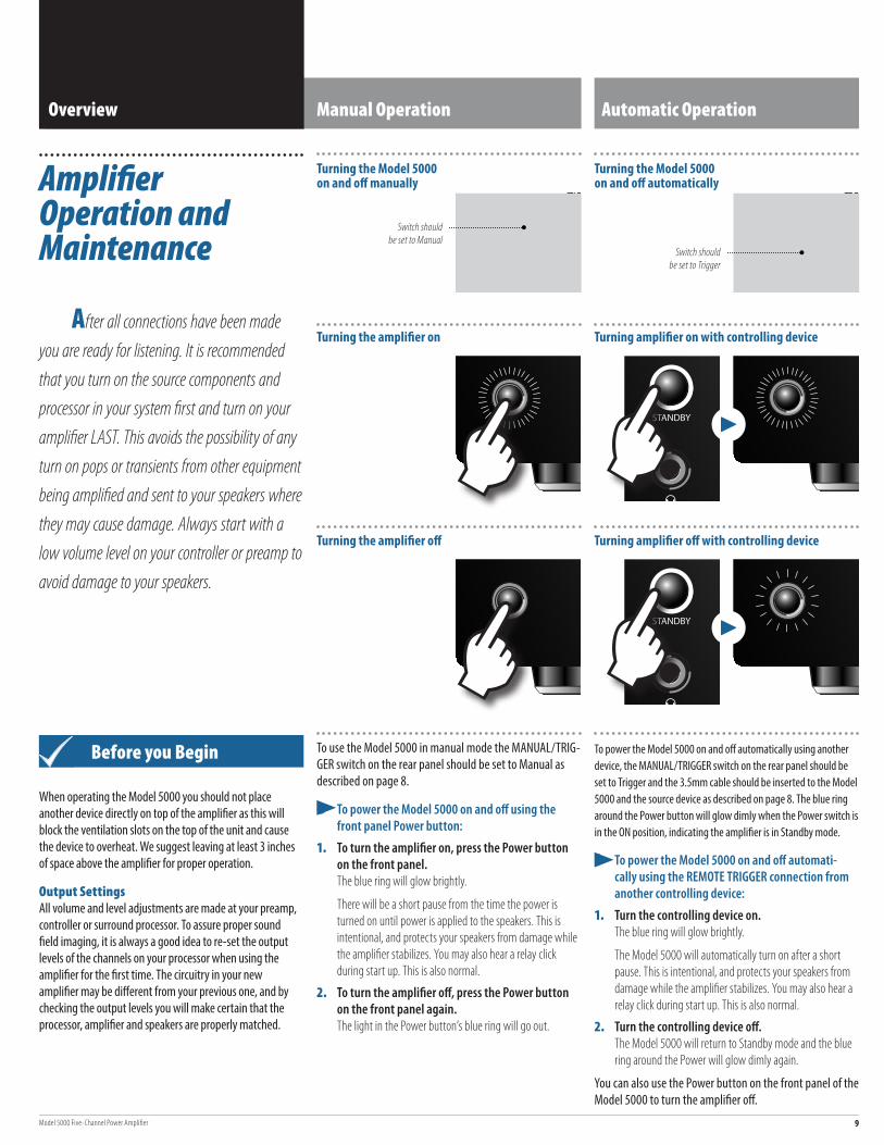
After all connections have been made you are ready for listening. It is recommended that you turn on the source components and processor in your system first and turn on your amplifier LAST. This avoids the possibility of any turn on pops or transients from other equipment being amplified and sent to your speakers where they may cause damage. Always start with a low volume level on your controller or preamp to avoid damage to your speakers.
Overview Manual Operation
To use the Model 5000 in manual mode the MANUAL/TRIG-GER switch on the rear panel should be set to Manual as described on page 8.
¼ To power the Model 5000 on and off using the front panel Power button:
1. To turn the amplifier on, press the Power button on the front panel.The blue ring will glow brightly.
There will be a short pause from the time the power is turned on until power is applied to the speakers. This is intentional, and protects your speakers from damage while the amplifier stabilizes. You may also hear a relay click during start up. This is also normal.
2. To turn the amplifier off, press the Power button on the front panel again.The light in the Power button’s blue ring will go out.
Automatic Operation
To power the Model 5000 on and off automatically using another device, the MANUAL/TRIGGER switch on the rear panel should be set to Trigger and the 3.5mm cable should be inserted to the Model 5000 and the source device as described on page 8. The blue ring around the Power button will glow dimly when the Power switch is in the ON position, indicating the amplifier is in Standby mode.
¼ To power the Model 5000 on and off automati-cally using the REMOTE TRIGGER connection from another controlling device:
1. Turn the controlling device on.The blue ring will glow brightly.
The Model 5000 will automatically turn on after a short pause. This is intentional, and protects your speakers from damage while the amplifier stabilizes. You may also hear a relay click during start up. This is also normal.
2. Turn the controlling device off. The Model 5000 will return to Standby mode and the blue ring around the Power will glow dimly again.
You can also use the Power button on the front panel of the Model 5000 to turn the amplifier off.
Before you Begin
When operating the Model 5000 you should not place another device directly on top of the amplifier as this will block the ventilation slots on the top of the unit and cause the device to overheat. We suggest leaving at least 3 inches of space above the amplifier for proper operation.
Output SettingsAll volume and level adjustments are made at your preamp, controller or surround processor. To assure proper sound field imaging, it is always a good idea to re-set the output levels of the channels on your processor when using the amplifier for the first time. The circuitry in your new amplifier may be different from your previous one, and by checking the output levels you will make certain that the processor, amplifier and speakers are properly matched.
Turning the amplifier on Turning amplifier on with controlling device
Turning the amplifier off Turning amplifier off with controlling device
Switch should be set to Manual
Switch should be set to Trigger

Outlaw Audio10
Your Outlaw Model 5000 Five-Channel Amplifier is designed for trouble free operation. If you follow the instructions in this manual you should enjoy many years of high quality listening enjoyment. However, as with any sophisticated electronic device, there may be occasional problems upon initial installation, or during the life of the unit. The items on this list are a brief guide
Cleaning
If the unit becomes dirty, wipe with a clean, soft, dry cloth. If necessary, first use a soft cloth slightly dampened with mild soapy water, then a fresh cloth dampened with clean water. Wipe dry immediately with a dry cloth. NEVER use benzene, thinner, alcohol or any other volatile cleaning agent that contains ammonia. Do not use abrasive clean-ers, as they may damage the finish of the metal parts. Avoid spraying insecticide, waxes, polishing agents, or any aerosol product near the unit.
Troubleshooting and Service Information
to the minor problems that you may be able to correct yourself. If these solutions do not rectify a problem, or if the problem persists, contact us for assistance. The Outlaw 5000 does not contain any internal user service-able parts. If you suspect a problem that may require service assistance, contact us at [email protected], or by phone at 866-688-5292.
It is important that any repairs be carried out only by Outlaw Audio Service Department. This will assure proper service and preserve the protection of your Limited Warranty. Keep your sales slip or receipt in a safe place with this manual so that it will be available to verify the purchase date, should you experience a problem covered by our warranty.
Using the amplifier’s front panel Power button will not affect the correct operation of the controlling device.
¼ To power the Model 5000 on and off manually when the REMOTE TRIGGER cable is connected to another controlling device and the rear panel switch is set to Trigger:
1. To turn the amplifier off, press the Power button on the front panel. This will turn off the master power to the Model 5000, the blue light will not be lit, and the amplifier will no longer be able to be turned on by the controlling device.
The amplifier will remain off, if you turn the controlling device off after powering down the Model 5000 manually.
2. To turn the amplifier on, press the Power button on the front panel.
If the controlling device is off, this will return the amp to Standby mode, and the blue ring will glow dimly. If the controlling device is on, the blue ring will glow brightly.
The amplifier will remain on, if you turn the controlling device on after powering up the Model 5000 manually.
When You Are Away
If you won’t be using your system for an extended period of time, it is always a good idea to turn the unit off using the amplifier’s front panel Power button and disconnect the AC power cord. This will prevent the Model 5000 from accidentally turning on during your absence.
Symptom Possible Cause Solution Option
Amplifier will not turn on when the front panel Power button is pressed
¼ MANUAL/TRIGGER switch set incorrectly ¼ No AC power ¼ Power strip or conditioner turned off ¼ External fuse may be blown
¼ Make certain MANUAL/TRIGGER switch is set to Manual. ¼ Make certain AC power cord is plugged into a live outlet. ¼ Make certain power strip or power conditioner is turned on, if applicable. ¼ Check rear panel fuse and replace if necessary. If the fuse blows again, please contact
Outlaw Customer Service.
Amplifier will not turn on when controlling device is turned on
¼ MANUAL/TRIGGER switch set incorrectly ¼ Remote trigger cable not properly connected ¼ No AC power ¼ Power strip or conditioner turned off
¼ Make certain MANUAL/TRIGGER switch is set to Trigger. ¼ Verify connection of trigger cable at both ends ¼ Make certain AC power cord is plugged into a live outlet. ¼ Make certain power strip or power conditioner is turned on, if applicable.
Amplifier turns on, but no audio from one or more channels
¼ Input plugs not connected to proper jack or are loose ¼ Speakers not connected properly
¼ Check input connections. ¼ Check speaker connections at amp and speaker.
Front panel light glows red when turned on
¼ One or more channels may have gone into protection mode ¼ One or more channels may not be functioning properly
Check for any speakers not producing sound. Turn the amplifier off. see "Protection Mode" on the following page. If the protection was set off because of thermal overload, it may take up to 30 minutes for the unit to cool down and reset the front LED. The unit should be cool to the touch when its ready to be turned back on.
If after waiting the light does not glow blue again, please call Outlaw customer service.
Audio levels differ Improper settings or output levels from the processor or controller Check the settings on your preamp, processor or controller.
Audio plays, then cuts off Amplifier shorted See suggestions in the section titled ”Protection Mode” on the next page.
Audible hum, or a discernable low frequency noise
Possible ground loop situation See suggestions in the section titled ”A Few Words About Hum and Noise” on the next page.
Model 5000 Five-Channel Power Amplifier 11
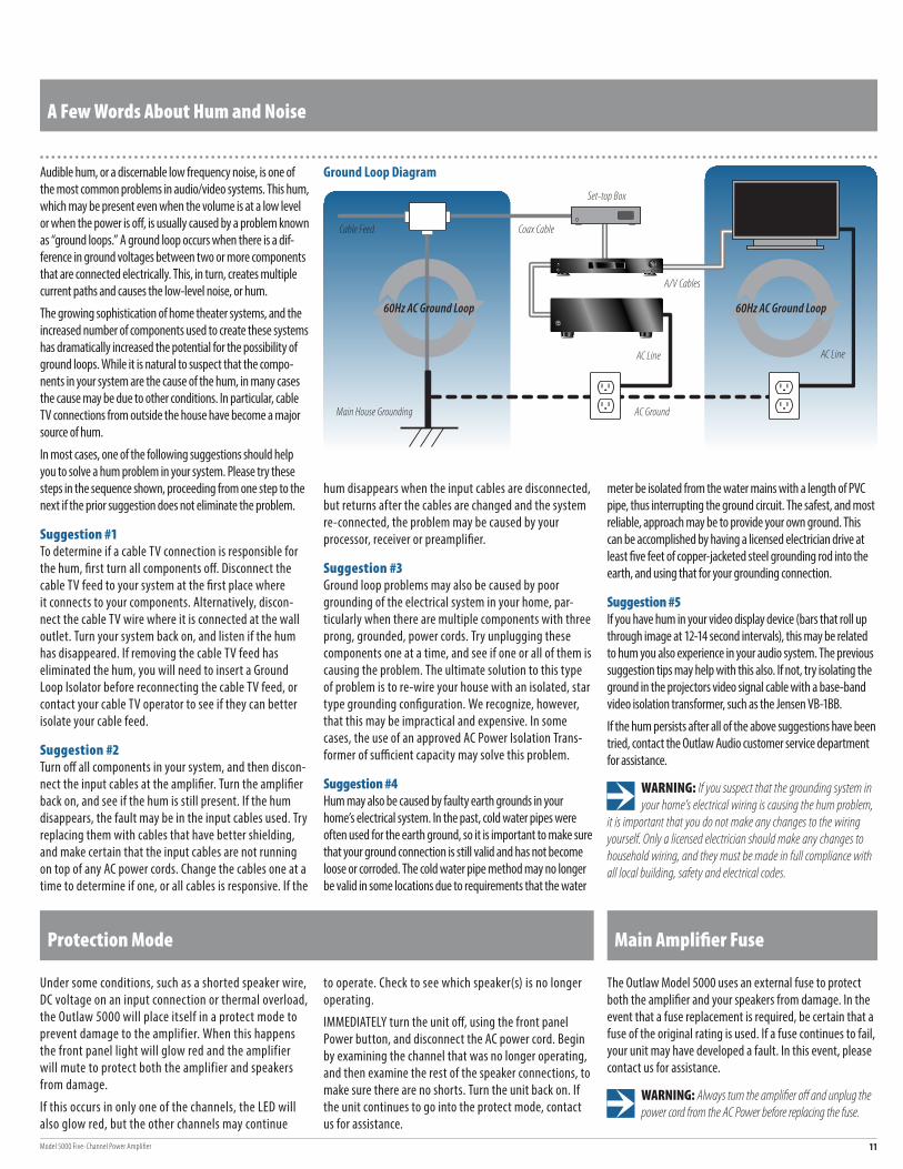
Ground Loop Diagram
The Outlaw Model 5000 uses an external fuse to protect both the amplifier and your speakers from damage. In the event that a fuse replacement is required, be certain that a fuse of the original rating is used. If a fuse continues to fail, your unit may have developed a fault. In this event, please contact us for assistance.
WARNING: Always turn the amplifier off and unplug the power cord from the AC Power before replacing the fuse.
Main Amplifier Fuse
Under some conditions, such as a shorted speaker wire, DC voltage on an input connection or thermal overload, the Outlaw 5000 will place itself in a protect mode to prevent damage to the amplifier. When this happens the front panel light will glow red and the amplifier will mute to protect both the amplifier and speakers from damage.
If this occurs in only one of the channels, the LED will also glow red, but the other channels may continue
Audible hum, or a discernable low frequency noise, is one of the most common problems in audio/video systems. This hum, which may be present even when the volume is at a low level or when the power is off, is usually caused by a problem known as “ground loops.” A ground loop occurs when there is a dif-ference in ground voltages between two or more components that are connected electrically. This, in turn, creates multiple current paths and causes the low-level noise, or hum.
The growing sophistication of home theater systems, and the increased number of components used to create these systems has dramatically increased the potential for the possibility of ground loops. While it is natural to suspect that the compo-nents in your system are the cause of the hum, in many cases the cause may be due to other conditions. In particular, cable TV connections from outside the house have become a major source of hum.
In most cases, one of the following suggestions should help you to solve a hum problem in your system. Please try these steps in the sequence shown, proceeding from one step to the next if the prior suggestion does not eliminate the problem.
Suggestion #1To determine if a cable TV connection is responsible for the hum, first turn all components off. Disconnect the cable TV feed to your system at the first place where it connects to your components. Alternatively, discon-nect the cable TV wire where it is connected at the wall outlet. Turn your system back on, and listen if the hum has disappeared. If removing the cable TV feed has eliminated the hum, you will need to insert a Ground Loop Isolator before reconnecting the cable TV feed, or contact your cable TV operator to see if they can better isolate your cable feed.
Suggestion #2Turn off all components in your system, and then discon-nect the input cables at the amplifier. Turn the amplifier back on, and see if the hum is still present. If the hum disappears, the fault may be in the input cables used. Try replacing them with cables that have better shielding, and make certain that the input cables are not running on top of any AC power cords. Change the cables one at a time to determine if one, or all cables is responsive. If the
hum disappears when the input cables are disconnected, but returns after the cables are changed and the system re-connected, the problem may be caused by your processor, receiver or preamplifier.
Suggestion #3Ground loop problems may also be caused by poor grounding of the electrical system in your home, par-ticularly when there are multiple components with three prong, grounded, power cords. Try unplugging these components one at a time, and see if one or all of them is causing the problem. The ultimate solution to this type of problem is to re-wire your house with an isolated, star type grounding configuration. We recognize, however, that this may be impractical and expensive. In some cases, the use of an approved AC Power Isolation Trans-former of sufficient capacity may solve this problem.
Suggestion #4Hum may also be caused by faulty earth grounds in your home’s electrical system. In the past, cold water pipes were often used for the earth ground, so it is important to make sure that your ground connection is still valid and has not become loose or corroded. The cold water pipe method may no longer be valid in some locations due to requirements that the water
meter be isolated from the water mains with a length of PVC pipe, thus interrupting the ground circuit. The safest, and most reliable, approach may be to provide your own ground. This can be accomplished by having a licensed electrician drive at least five feet of copper-jacketed steel grounding rod into the earth, and using that for your grounding connection.
Suggestion #5If you have hum in your video display device (bars that roll up through image at 12-14 second intervals), this may be related to hum you also experience in your audio system. The previous suggestion tips may help with this also. If not, try isolating the ground in the projectors video signal cable with a base-band video isolation transformer, such as the Jensen VB-1BB.
If the hum persists after all of the above suggestions have been tried, contact the Outlaw Audio customer service department for assistance.
WARNING: If you suspect that the grounding system in your home’s electrical wiring is causing the hum problem,
it is important that you do not make any changes to the wiring yourself. Only a licensed electrician should make any changes to household wiring, and they must be made in full compliance with all local building, safety and electrical codes.
Protection Mode
to operate. Check to see which speaker(s) is no longer operating.
IMMEDIATELY turn the unit off, using the front panel Power button, and disconnect the AC power cord. Begin by examining the channel that was no longer operating, and then examine the rest of the speaker connections, to make sure there are no shorts. Turn the unit back on. If the unit continues to go into the protect mode, contact us for assistance.
A Few Words About Hum and Noise
60Hz AC Ground Loop 60Hz AC Ground Loop
AC Ground
AC Line
A/V Cables
Main House Grounding
Cable Feed Coax Cable
AC Line
Set-top Box

Outlaw Audio12
The Outlaw Audio 30-Day Satisfaction Guarantee
This product is guaranteed to satisfy all your needs for a high performance power amplifier. If for any reason, you are not completely satisfied with it, please contact us at 866-OUTLAWS (688-5297) within 30 days of receipt of the unit and you will receive a return authorization.
The original box and packing materials are required for all returns. We recommend that you keep the packing (even after 30 days) so that if you ever move, or the amplifier
requires service, the unit will be adequately protected.
If you decide to return the amplifier, the only cost you will be responsible for is the original shipping charge at time of purchase. When your amplifier arrives, we will inspect it to insure that it was shipped back to us in original condition with all of the accessories. Upon satisfactory inspection, we will issue a credit for your original purchase price less your original outbound freight cost.
Designed in the USA by Outlaw Audio and manufactured in the P.R. China
Amplifier Section
Power Output 120 watts RMS x 5 (all channels driven simultaneously into 8 ohms from 20Hz–20kHz with less than 0.02% total harmonic distortion, A-weight filter). 180 watts RMS x 5 (all channels driven simultaneously into 4 ohms from 20Hz–20kHz with less than 0.03% total harmonic distortion, A-weight filter).
Frequency Response 20Hz -20kHz +/- 0.5 dB at rated output (120W)
Total Harmonic Distortion Less than 0.02% at rated output (THD) (120W), all frequencies, less than 0.01% at 1kHz
Intermodulation Distortion Less than 0.05% from 250mV to output (IMD) full rated output (120W)
Filter Capacitance Four 6800µF Caps per channel
Number of Output Devices 4 per channel
Power Bandwidth 5Hz - 54kHz +0/-3 dB
Damping Factor Greater than 105 from 10Hz to 400Hz
Crosstalk Greater than -70dB from 20Hz – 20kHz Gain Voltage gain of 29dB
Input Impedance 40k ohms
Input Sensitivity 1.00 Volt
Remote Trigger Voltage 9 - 24 Volts DC at 5 milliamperes or greater
General
Dimensions including 6.0" x 17.0" x 16.75" feet (HxWxD)
Weight 50 lbs
Power Requirements 120VAC, ±3%, 50Hz - 60Hz 1500 watts maximum
Specifications
Outlaw Audio Limited Warranty
charges if the repairs are covered by the warranty. Please save the original shipping cartons as the unit MUST be returned in the original carton and packing. (Replace-ment cartons are available for purchase.)
If your product needs service, please call Outlaw Audio, LLC. at 866-OUTLAWS (688-5297).
You will need to present proof of purchase to establish warranty status. For warranty service, proof of purchase or proof of warranty transfer is required. In the event that such proof cannot be provided, non-warranty service is available, provided that the serial number label has not been altered in any manner.
In the event that you wish to return your Outlaw Product back to us, for any reason, please call to arrange for a Return Authorization Number. This will ensure that your problem is discussed with a service technician who will determine if there is a quick solution to your problem.
Outlaw Audio shall not be liable for, or in any way respon-sible for, any incidental or consequential damages of any kind. Some states do not allow limitations on how long an implied warranty lasts and/or do not allow the exclusion of incidental or consequential damages, therefore, the limita-tions and exclusions stated herein may not apply to you. This warranty gives you specific legal rights; and you may also have other rights which vary from state to state.
THERE ARE NO WARRANTIES GIVEN BY OUTLAW AUDIO WHICH EXTEND BEYOND THE DESCRIPTION GIVEN HEREIN. ANY IMPLIED WARRANTIES OF FITNESS FOR PURPOSE SOLD, MERCHANTABILITY, DESCRIPTION, QUALITY OR ANY OTHER MATTERS ARE LIMITED TO THE TERMS OF THE EXPRESSED LIMITED WARRANTY STATED HEREIN.
Products are sold on the basis of specifications applicable at the time of sales. Outlaw Audio shall have no obligation to modify products once they have been sold.
This warranty is applicable only in North America.
For applicability in other countries, please call Outlaw Audio, LLC.
® Outlaw Audio, LLC.
This warranty protects the owner of the Outlaw Model 5000 Power Amplifier (the PRODUCT) for five (5) years from the date of purchase.
This warranty covers all defects in material and workman-ship with the following specific exceptions. These are:
¼ Damage caused by improper installation or adjustment
¼ Damage caused by accident, unreasonable use or neglect, or acts of God
¼ Damage from failure to follow instructions contained in this Owner’s Manual
¼ Damage from the performance of repairs by someone not authorized by Outlaw Audio
¼ Any unit on which the serial number has been effaced, modified, or removed
¼ Damage occurring during shipment
¼ Units which have been altered or modified in design, appearance or construction
This warranty covers only the actual defects within the PRODUCT itself. IT DOES NOT cover any installation or removal costs, normal setup costs, claims based on any misrepresen-tation by the seller, or performance variations resulting from installation related circumstances such as signal quality, AC power or incompatibilities with speakers and/or other system components.
During the warranty period, Outlaw Audio will, at its option, either repair the defect, or replace the defective product, or the defective parts, or components thereof at no charge to the owner for parts and labor covered by this warranty. If necessary repairs are not covered by this warranty, or if a unit is examined which is not in need of repair, you will be charged for the repairs and/or the examination. If non-warranted repairs are needed, we will notify you of the estimated cost and ask for your authorization to perform said repairs.
You must pay shipping charges incurred in getting your Product to Outlaw. We will pay the return shipping