Embed Size (px)
Citation preview
Page 1 of 8 IN014 Rev I
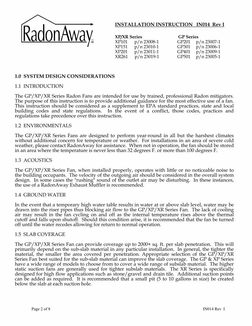
Please Read And Save These Instructions DO NOT CONNECT POWER SUPPLY UNTIL FAN IS COMPLETELY INSTALLED. MAKE SURE ELECTRICAL SERVICE TO FAN IS LOCKED IN "OFF" POSITION. DISCONNECT POWER BEFORE SERVICING FAN.
1. WARNING! Do not use fan in hazardous environments where fan electrical system could provide ignition to combustible of flammable materials. 2. WARNING! Do not use fan to pump explosive or corrosive gases. 3. WARNING! Check voltage at the fan to insure it corresponds with nameplate. 4. WARNING! Normal operation of this device may affect the combustion airflow needed for safe operation of fuel burning equipment. Check for possible backdraft conditions on all combustion devices after installation. 5. NOTICE! There are no user serviceable parts located inside the fan unit. Do NOT attempt to open. Return unit to the factory for service. 6. All wiring must be performed in accordance with the National Fire Protection Association’s (NFPA)”National Electrical Code, Standard #70”-current edition for all commercial and industrial work, and state and local building codes. All wiring must be performed by a qualified and licensed electrician. 7. WARNING! Do not leave fan unit installed on system piping without electrical power for more than 48 hours. Fan failure could result from this non-operational storage. 8. WARNING - TO REDUCE THE RISK OF FIRE, ELECTRIC SHOCK, OR INJURY TO PERSONS, OBSERVE THE FOLLOWING: a) Use this unit only in the manner intended by the manufacturer. If you have questions, contact the manufacturer. b) Before servicing or cleaning unit, switch power off at service panel and lock the service disconnecting means to prevent power from being switched on accidentally. When the service disconnecting means cannot be locked, securely fasten a prominent warning device, such as a tag, to the service panel
Page 2 of 8 IN014 Rev I
INSTALLATION INSTRUCTION IN014 Rev I XP/XR Series GP Series XP101 p/n 23008-1 GP201 p/n 23007-1 XP151 p/n 23010-1 GP301 p/n 23006-1 XP201 p/n 23011-1 GP401 p/n 23009-1 XR261 p/n 23019-1 GP501 p/n 23005-1
1.0 SYSTEM DESIGN CONSIDERATIONS 1.1 INTRODUCTION The GP/XP/XR Series Radon Fans are intended for use by trained, professional Radon mitigators. The purpose of this instruction is to provide additional guidance for the most effective use of a fan. This instruction should be considered as a supplement to EPA standard practices, state and local building codes and state regulations. In the event of a conflict, those codes, practices and regulations take precedence over this instruction. 1.2 ENVIRONMENTALS The GP/XP/XR Series Fans are designed to perform year-round in all but the harshest climates without additional concern for temperature or weather. For installations in an area of severe cold weather, please contact RadonAway for assistance. When not in operation, the fan should be stored in an area where the temperature is never less than 32 degrees F. or more than 100 degrees F. 1.3 ACOUSTICS The GP/XP/XR Series Fan, when installed properly, operates with little or no noticeable noise to the building occupants. The velocity of the outgoing air should be considered in the overall system design. In some cases the "rushing" sound of the outlet air may be disturbing. In these instances, the use of a RadonAway Exhaust Muffler is recommended. 1.4 GROUND WATER In the event that a temporary high water table results in water at or above slab level, water may be drawn into the riser pipes thus blocking air flow to the GP/XP/XR Series Fan. The lack of cooling air may result in the fan cycling on and off as the internal temperature rises above the thermal cutoff and falls upon shutoff. Should this condition arise, it is recommended that the fan be turned off until the water recedes allowing for return to normal operation. 1.5 SLAB COVERAGE The GP/XP/XR Series Fan can provide coverage up to 2000+ sq. ft. per slab penetration. This will primarily depend on the sub-slab material in any particular installation. In general, the tighter the material, the smaller the area covered per penetration. Appropriate selection of the GP/XP/XR Series Fan best suited for the sub-slab material can improve the slab coverage. The GP & XP Series have a wide range of models to choose from to cover a wide range of subslab material. The higher static suction fans are generally used for tighter subslab materials. The XR Series is specifically designed for high flow applications such as stone/gravel and drain tile. Additional suction points can be added as required. It is recommended that a small pit (5 to 10 gallons in size) be created below the slab at each suction hole.
Page 3 of 8 IN014 Rev I
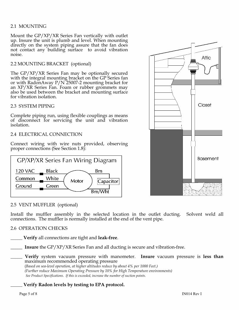
1.6 CONDENSATION & DRAINAGE Condensation is formed in the piping of a mitigation system when the air in the piping is chilled below its dew point. This can occur at points where the system piping goes through unheated space such as an attic, garage or outside. The system design must provide a means for water to drain back to a slab hole to remove the condensation. The GP/XP/XR Series Fan MUST be mounted vertically plumb and level, with the outlet pointing up for proper drainage through the fan. Avoid mounting the fan in any orientation that will allow water to accumulate inside the fan housing. The GP/XP/XR Series Fans are NOT suitable for underground burial. For GP/XP/XR Series Fan piping, the following table provides the minimum recommended pipe diameter and pitch under several system conditions.
Pipe Minimum Rise per Foot of Run* Dia. @25 CFM @50 CFM @100 CFM
4” 1/8” 1/4” 3/8” 3" 1/4" 3/8" 1 1/2"
*Typical GP/XP/XR Series Fan operational flow rate is 25 - 90 CFM. (For more precision, determine flow rate by using the chart in the addendum.)
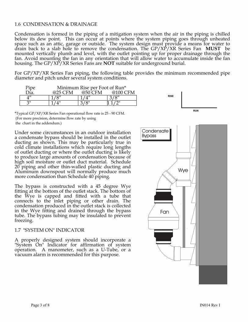
Under some circumstances in an outdoor installation a condensate bypass should be installed in the outlet ducting as shown. This may be particularly true in cold climate installations which require long lengths of outlet ducting or where the outlet ducting is likely to produce large amounts of condensation because of high soil moisture or outlet duct material. Schedule 20 piping and other thin-walled plastic ducting and Aluminum downspout will normally produce much more condensation than Schedule 40 piping. The bypass is constructed with a 45 degree Wye fitting at the bottom of the outlet stack. The bottom of the Wye is capped and fitted with a tube that connects to the inlet piping or other drain. The condensation produced in the outlet stack is collected in the Wye fitting and drained through the bypass tube. The bypass tubing may be insulated to prevent freezing. 1.7 "SYSTEM ON" INDICATOR A properly designed system should incorporate a "System On" Indicator for affirmation of system operation. A manometer, such as a U-Tube, or a vacuum alarm is recommended for this purpose.
RUN
RISE
Page 4 of 8 IN014 Rev I
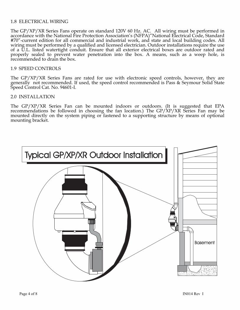
1.8 ELECTRICAL WIRING The GP/XP/XR Series Fans operate on standard 120V 60 Hz. AC. All wiring must be performed in accordance with the National Fire Protection Association’s (NFPA)”National Electrical Code, Standard #70”-current edition for all commercial and industrial work, and state and local building codes. All wiring must be performed by a qualified and licensed electrician. Outdoor installations require the use of a U.L. listed watertight conduit. Ensure that all exterior electrical boxes are outdoor rated and properly sealed to prevent water penetration into the box. A means, such as a weep hole, is recommended to drain the box. 1.9 SPEED CONTROLS The GP/XP/XR Series Fans are rated for use with electronic speed controls, however, they are generally not recommended. If used, the speed control recommended is Pass & Seymour Solid State Speed Control Cat. No. 94601-I. 2.0 INSTALLATION The GP/XP/XR Series Fan can be mounted indoors or outdoors. (It is suggested that EPA recommendations be followed in choosing the fan location.) The GP/XP/XR Series Fan may be mounted directly on the system piping or fastened to a supporting structure by means of optional mounting bracket.
Page 5 of 8 IN014 Rev I
2.1 MOUNTING Mount the GP/XP/XR Series Fan vertically with outlet up. Insure the unit is plumb and level. When mounting directly on the system piping assure that the fan does not contact any building surface to avoid vibration noise. 2.2 MOUNTING BRACKET (optional) The GP/XP/XR Series Fan may be optionally secured with the integral mounting bracket on the GP Series fan or with RadonAway P/N 25007-2 mounting bracket for an XP/XR Series Fan. Foam or rubber grommets may also be used between the bracket and mounting surface for vibration isolation. 2.3 SYSTEM PIPING Complete piping run, using flexible couplings as means of disconnect for servicing the unit and vibration isolation. 2.4 ELECTRICAL CONNECTION Connect wiring with wire nuts provided, observing proper connections (See Section 1.8): 2.5 VENT MUFFLER (optional) Install the muffler assembly in the selected location in the outlet ducting. Solvent weld all connections. The muffler is normally installed at the end of the vent pipe. 2.6 OPERATION CHECKS _____ Verify all connections are tight and leak-free. _____ Insure the GP/XP/XR Series Fan and all ducting is secure and vibration-free. _____ Verify system vacuum pressure with manometer. Insure vacuum pressure is less than
maximum recommended operating pressure (Based on sea-level operation, at higher altitudes reduce by about 4% per 1000 Feet.) (Further reduce Maximum Operating Pressure by 10% for High Temperature environments) See Product Specifications. If this is exceeded, increase the number of suction points.
_____ Verify Radon levels by testing to EPA protocol.
Page 6 of 8 IN014 Rev I
XP/XR SERIES PRODUCT SPECIFICATIONS
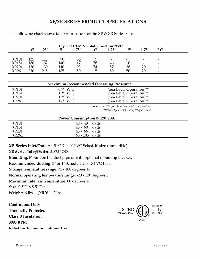
The following chart shows fan performance for the XP & XR Series Fan: Typical CFM Vs Static Suction "WC 0" .25" .5" .75" 1.0" 1.25" 1.5" 1.75" 2.0" XP101 125 118 90 56 5 - - - - XP151 180 162 140 117 78 46 10 - - XP201 150 130 110 93 74 57 38 20 - XR261 250 215 185 150 115 80 50 20 -
Maximum Recommended Operating Pressure* XP101 0.9" W.C. (Sea Level Operation)** XP151 1.3" W.C. (Sea Level Operation)** XP201 1.7" W.C. (Sea Level Operation)** XR261 1.6" W.C. (Sea Level Operation)**
*Reduce by 10% for High Temperature Operation **Reduce by 4% per 1000 feet of altitude
Power Consumption @ 120 VAC XP101 40 - 49 watts XP151 45 - 60 watts XP201 45 - 66 watts XR261 65 - 105 watts
XP Series Inlet/Outlet: 4.5" OD (4.0" PVC Sched 40 size compatible) XR Series Inlet/Outlet: 5.875" OD Mounting: Mount on the duct pipe or with optional mounting bracket. Recommended ducting: 3" or 4" Schedule 20/40 PVC Pipe Storage temperature range: 32 - 100 degrees F. Normal operating temperature range: -20 - 120 degrees F. Maximum inlet air temperature: 80 degrees F. Size: 9.5H" x 8.5" Dia. Weight: 6 lbs. (XR261 - 7 lbs) Continuous Duty Thermally Protected Class B Insulation 3000 RPM Rated for Indoor or Outdoor Use
Page 7 of 8 IN014 Rev I
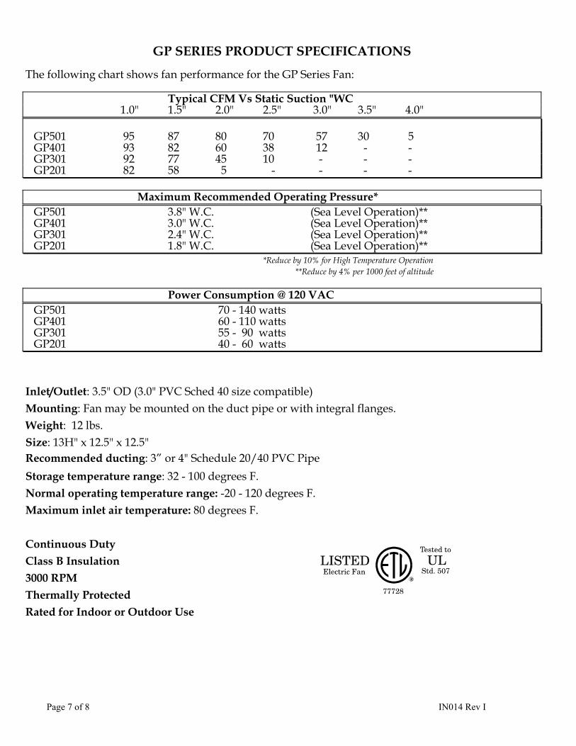
GP SERIES PRODUCT SPECIFICATIONS The following chart shows fan performance for the GP Series Fan: Typical CFM Vs Static Suction "WC 1.0" 1.5" 2.0" 2.5" 3.0" 3.5" 4.0" GP501 95 87 80 70 57 30 5 GP401 93 82 60 38 12 - - GP301 92 77 45 10 - - - GP201 82 58 5 - - - -
Maximum Recommended Operating Pressure* GP501 3.8" W.C. (Sea Level Operation)** GP401 3.0" W.C. (Sea Level Operation)** GP301 2.4" W.C. (Sea Level Operation)** GP201 1.8" W.C. (Sea Level Operation)**
*Reduce by 10% for High Temperature Operation **Reduce by 4% per 1000 feet of altitude
Power Consumption @ 120 VAC GP501 70 - 140 watts GP401 60 - 110 watts GP301 55 - 90 watts GP201 40 - 60 watts Inlet/Outlet: 3.5" OD (3.0" PVC Sched 40 size compatible) Mounting: Fan may be mounted on the duct pipe or with integral flanges. Weight: 12 lbs. Size: 13H" x 12.5" x 12.5" Recommended ducting: 3” or 4" Schedule 20/40 PVC Pipe
Storage temperature range: 32 - 100 degrees F. Normal operating temperature range: -20 - 120 degrees F. Maximum inlet air temperature: 80 degrees F. Continuous Duty Class B Insulation 3000 RPM Thermally Protected Rated for Indoor or Outdoor Use
Page 8 of 8 IN014 Rev I
IMPORTANT INSTRUCTIONS TO INSTALLER
Inspect the GPx01/XP/XR Series Fan for shipping damage within 15 days of receipt. Notify RadonAway of any damages immediately. Radonaway is not responsible for damages incurred during shipping. However, for your benefit, Radonaway does insure shipments. There are no user serviceable parts inside the fan. Do not attempt to open. Return unit to factory for service. Install the GPx01/XP/XR Series Fan in accordance with all EPA standard practices, and state and local building codes and state regulations.
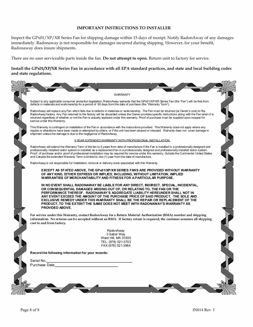
WARRANTY
Subject to any applicable consumer protection legislation, RadonAway warrants that the GPx01/XP/XR Series Fan (the “Fan”) will be free from defects in materials and workmanship for a period of 90 days from the date of purchase (the “Warranty Term”). RadonAway will replace any Fan which fails due to defects in materials or workmanship. The Fan must be returned (at Owner’s cost) to the RadonAway factory. Any Fan returned to the factory will be discarded unless the Owner provides specific instructions along with the Fan when it is returned regardless of whether or not the Fan is actually replaced under this warranty. Proof of purchase must be supplied upon request for service under this Warranty. This Warranty is contingent on installation of the Fan in accordance with the instructions provided. This Warranty does not apply where any repairs or alterations have been made or attempted by others, or if the unit has been abused or misused. Warranty does not cover damage in shipment unless the damage is due to the negligence of RadonAway.
5 YEAR EXTENDED WARRANTY WITH PROFESSIONAL INSTALLATION. RadonAway will extend the Warranty Term of the fan to 5 years from date of manufacture if the Fan is installed in a professionally designed and professionally installed radon system or installed as a replacement fan in a professionally designed and professionally installed radon system. Proof of purchase and/or proof of professional installation may be required for service under this warranty. Outside the Continental United States and Canada the extended Warranty Term is limited to one (1) year from the date of manufacture. RadonAway is not responsible for installation, removal or delivery costs associated with this Warranty.
EXCEPT AS STATED ABOVE, THE GPx01/XP/XR SERIES FANS ARE PROVIDED WITHOUT WARRANTY OF ANY KIND, EITHER EXPRESS OR IMPLIED, INCLUDING, WITHOUT LIMITATION, IMPLIED WARRANTIES OF MERCHANTABILITY AND FITNESS FOR A PARTICULAR PURPOSE.
IN NO EVENT SHALL RADONAWAY BE LIABLE FOR ANY DIRECT, INDIRECT, SPECIAL, INCIDENTAL, OR CONSEQUENTIAL DAMAGES ARISING OUT OF, OR RELATING TO, THE FAN OR THE PERFORMANCE THEREOF. RADONAWAY’S AGGREGATE LIABILITY HEREUNDER SHALL NOT IN ANY EVENT EXCEED THE AMOUNT OF THE PURCHASE PRICE OF SAID PRODUCT. THE SOLE AND EXCLUSIVE REMEDY UNDER THIS WARRANTY SHALL BE THE REPAIR OR REPLACEMENT OF THE PRODUCT, TO THE EXTENT THE SAME DOES NOT MEET WITH RADONAWAY’S WARRANTY AS PROVIDED ABOVE.
For service under this Warranty, contact RadonAway for a Return Material Authorization (RMA) number and shipping information. No returns can be accepted without an RMA. If factory return is required, the customer assumes all shipping cost to and from factory.
RadonAway 3 Saber Way
Ward Hill, MA 01835 TEL. (978) 521-3703 FAX (978) 521-3964
Record the following information for your records: Serial No. Purchase Date