Embed Size (px)
Citation preview
22-011 www.powercommander.com 2002-2009 Yamaha Road Star Warrior - PCV - 1
PARTS LIST
1 PowerCommander1 USBCable1 InstallationGuide2 PowerCommanderDecals2 DynojetDecals2 Velcrostrips1 Alcoholswab
THE LATEST POWER COMMANDER SOFTWARE AND MAP FILES CAN BE
DOWNLOADED FROM OUR WEB SITE AT:www.powercommander.com
2002-2009 YamahaRoad Star Warrior
I ns ta l l a t i on I ns t ruc t i ons
PLEASE READ ALL DIRECTIONS BEFORE STARTING INSTALLATION
THE IGNITION MUST BE TURNED OFF BEFORE INSTALLATION!
2191 Mendenhall Drive North Las Vegas, NV 89081 (800) 992-4993 www.powercommander.com
22-011 www.powercommander.com 2002-2009 Yamaha Road Star Warrior - PCV - 2
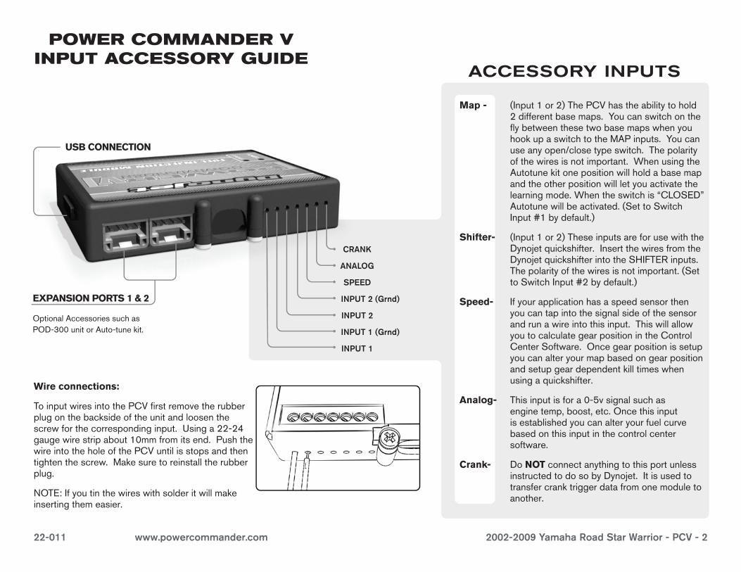
EXPANSION PORTS 1 & 2
OptionalAccessoriessuchasPOD-300unitorAuto-tunekit.
POWER COMMANDER V INPUT ACCESSORY GUIDE
Map - (Input1or2)ThePCVhastheabilitytohold2differentbasemaps.YoucanswitchontheflybetweenthesetwobasemapswhenyouhookupaswitchtotheMAPinputs.Youcanuseanyopen/closetypeswitch.Thepolarityofthewiresisnotimportant.WhenusingtheAutotunekitonepositionwillholdabasemapandtheotherpositionwillletyouactivatethelearningmode.Whentheswitchis“CLOSED”Autotunewillbeactivated.(SettoSwitchInput#1bydefault.)
Shifter- (Input1or2)TheseinputsareforusewiththeDynojetquickshifter.InsertthewiresfromtheDynojetquickshifterintotheSHIFTERinputs.Thepolarityofthewiresisnotimportant.(SettoSwitchInput#2bydefault.)
Speed- Ifyourapplicationhasaspeedsensorthenyoucantapintothesignalsideofthesensorandrunawireintothisinput.ThiswillallowyoutocalculategearpositionintheControlCenterSoftware.Oncegearpositionissetupyoucanalteryourmapbasedongearpositionandsetupgeardependentkilltimeswhenusingaquickshifter.
Analog- Thisinputisfora0-5vsignalsuchasenginetemp,boost,etc.Oncethisinputisestablishedyoucanalteryourfuelcurvebasedonthisinputinthecontrolcentersoftware.
Crank- DoNOTconnectanythingtothisportunlessinstructedtodosobyDynojet.Itisusedtotransfercranktriggerdatafromonemoduletoanother.
ACCESSORY INPUTS
Wire connections:
ToinputwiresintothePCVfirstremovetherubberplugonthebacksideoftheunitandloosenthescrewforthecorrespondinginput.Usinga22-24gaugewirestripabout10mmfromitsend.PushthewireintotheholeofthePCVuntilisstopsandthentightenthescrew.Makesuretoreinstalltherubberplug.
NOTE:Ifyoutinthewireswithsolderitwillmakeinsertingthemeasier.
CRANK
ANALOG
SPEED
INPUT 1 (Grnd)
INPUT 1
INPUT 2 (Grnd)
INPUT 2
USB CONNECTION
22-011 www.powercommander.com 2002-2009 Yamaha Road Star Warrior - PCV - 3
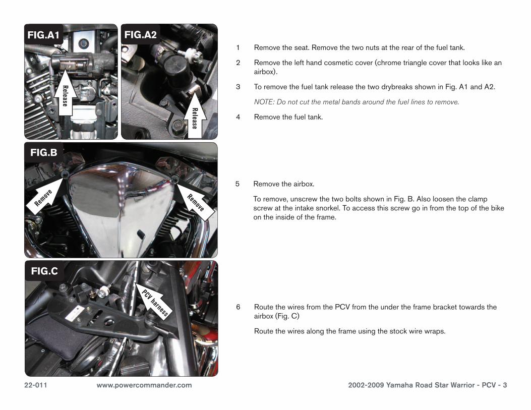
1 Removetheseat.Removethetwonutsattherearofthefueltank.
2 Removethelefthandcosmeticcover(chrometrianglecoverthatlookslikeanairbox).
3 ToremovethefueltankreleasethetwodrybreaksshowninFig.A1andA2.
NOTE: Do not cut the metal bands around the fuel lines to remove.
4 Removethefueltank.
5 Removetheairbox.
Toremove,unscrewthetwoboltsshowninFig.B.Alsoloosentheclampscrewattheintakesnorkel.Toaccessthisscrewgoinfromthetopofthebikeontheinsideoftheframe.
6 RoutethewiresfromthePCVfromtheundertheframebrackettowardstheairbox(Fig.C)
Routethewiresalongtheframeusingthestockwirewraps.
FIG.A1
FIG.C
Remove
Ground wire
FIG.B
Remove
FIG.A2
Release
Release
Remov
e
PCV harness
22-011 www.powercommander.com 2002-2009 Yamaha Road Star Warrior - PCV - 4
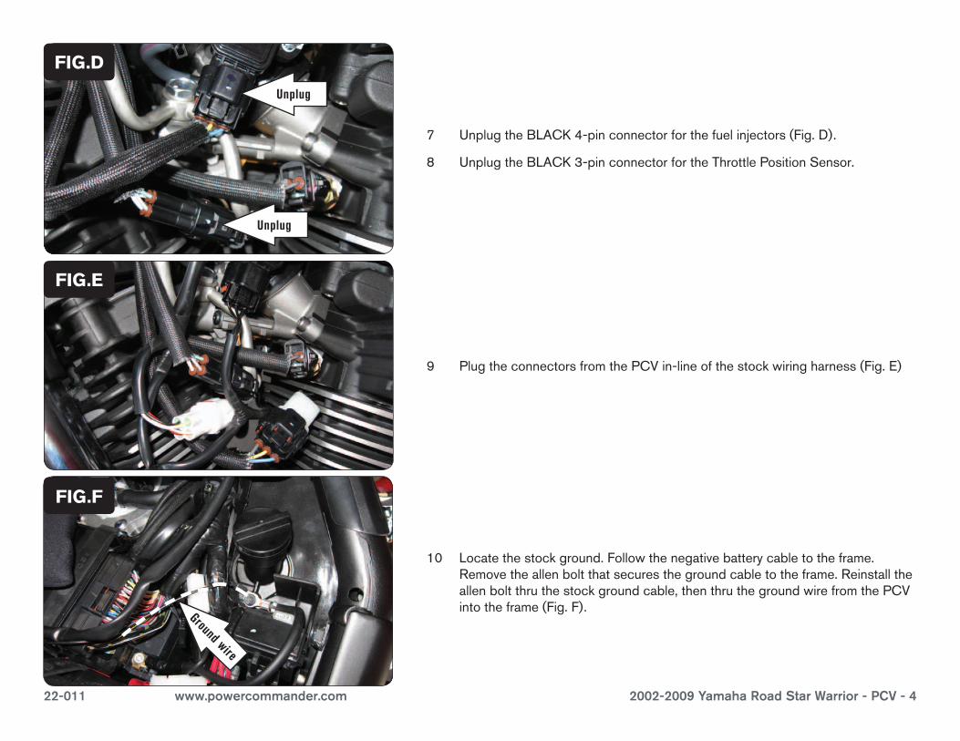
7 UnplugtheBLACK4-pinconnectorforthefuelinjectors(Fig.D).
8 UnplugtheBLACK3-pinconnectorfortheThrottlePositionSensor.
FIG.D
9 PlugtheconnectorsfromthePCVin-lineofthestockwiringharness(Fig.E)
FIG.E
10 Locatethestockground.Followthenegativebatterycabletotheframe.Removetheallenboltthatsecuresthegroundcabletotheframe.Reinstalltheallenboltthruthestockgroundcable,thenthruthegroundwirefromthePCVintotheframe(Fig.F).
FIG.F
Ground wire
Unplug
Unplug
22-011 www.powercommander.com 2002-2009 Yamaha Road Star Warrior - PCV - 5
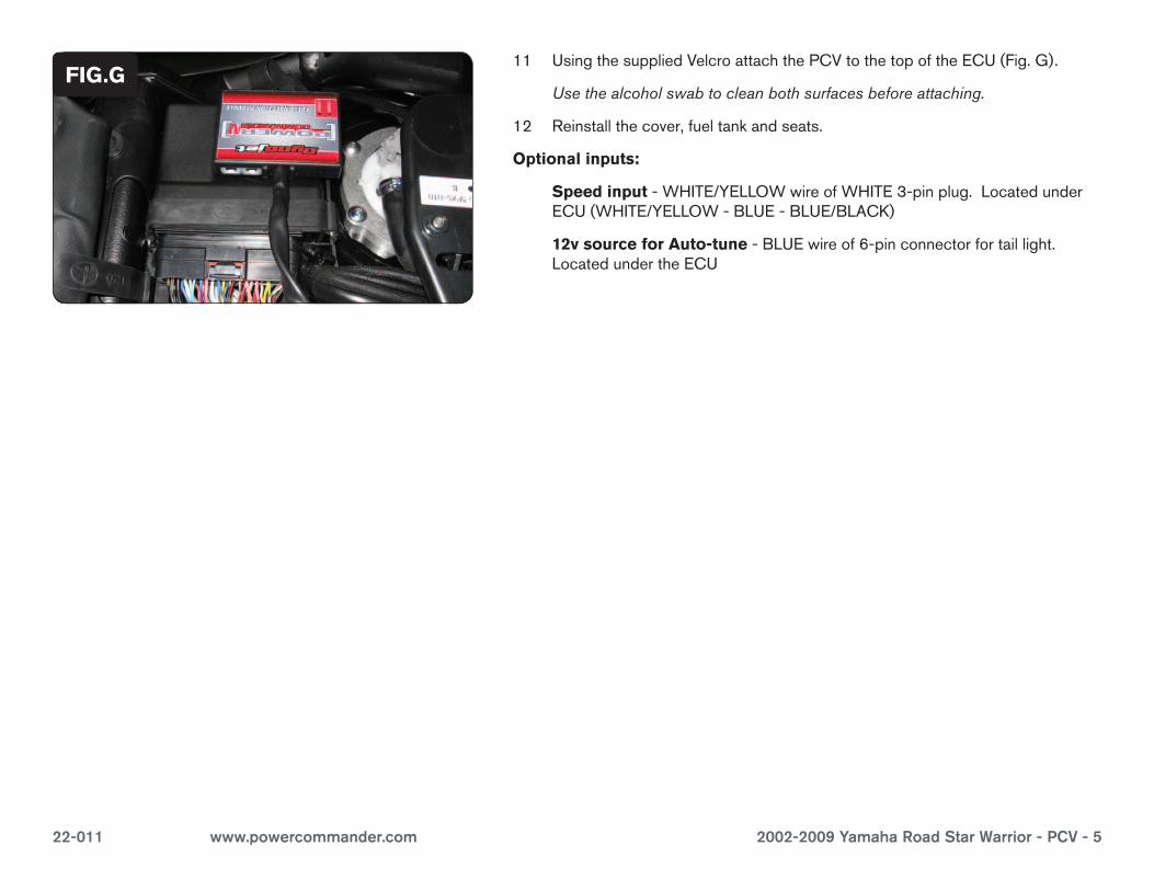
11 UsingthesuppliedVelcroattachthePCVtothetopoftheECU(Fig.G).
Usethealcoholswabtocleanbothsurfacesbeforeattaching.
12 Reinstallthecover,fueltankandseats.
Optional inputs:
Speed input-WHITE/YELLOWwireofWHITE3-pinplug.LocatedunderECU(WHITE/YELLOW-BLUE-BLUE/BLACK)
12v source for Auto-tune-BLUEwireof6-pinconnectorfortaillight.LocatedundertheECU
FIG.G