Embed Size (px)
Citation preview

Please put your box number on your homework from now on.
Box numbers are written in orange on the homework I am handing back.
They are also posted in the lobby.

We can use rays of light to see where images “are” or where they “appear” to be.

A planar interface (e.g. between water and air) can also make an image.
The location of the image depends on the viewing angle (unlike with mirrors.)

Why do oddly shaped curved mirrors make distorted images, rather than no image at all?
It’s certainly true that you can’t trace all the reflected rays (originating from a nose, for example) back to the same point!

A concave mirror with a radius of curvature of 20 cm has a focal length of
Q34.2
A. 40 cm.
B. 20 cm.
C. 10 cm.
D. 5 cm.
E. answer depends on the index of refraction of the air around the mirror

A concave mirror with a radius of curvature of 20 cm has a focal length of
A34.2
A. 40 cm.
B. 20 cm.
C. 10 cm.
D. 5 cm.
E. answer depends on the index of refraction of the air around the mirror

An object is placed 4.0 m away from a concave mirror of focal length +1.0 m. The image formed by the mirror is
Q34.3
A. real and larger than the object.
B. real and smaller than the object.
C. real and the same size as the object.
D. virtual and larger than the object.
E. virtual and smaller than the object.
An object is placed 4.0 m away from a concave mirror of focal length +1.0 m. The image formed by the mirror is
A34.3
A. real and larger than the object.
B. real and smaller than the object.
C. real and the same size as the object.
D. virtual and larger than the object.
E. virtual and smaller than the object.

Q34.6
A. real and larger than the object.
B. real and smaller than the object.
C. real and the same size as the object.
D. virtual and larger than the object.
E. virtual and smaller than the object.
An object is placed 0.5 m away from a concave mirror of focal length +1.0 m. The image formed by the mirror is

A34.6
A. real and larger than the object.
B. real and smaller than the object.
C. real and the same size as the object.
D. virtual and larger than the object.
E. virtual and smaller than the object.
An object is placed 0.5 m away from a concave mirror of focal length +1.0 m. The image formed by the mirror is

Ray tracing: parallel to axis through focus
MEMORIZE THIS!
Sign conventions for mirrors
Will not be given on eqn sheet… but you don’t need to memorize if you can ray trace!
Concave R>0 Convex R<0
Real Object or Image s,s’ > 0 Virtual object or image s, s’ < 0

Spherical refracting surface
Derivation - requires paraxial approximationSign convention CONVEX = +
NOTE: if s = ∞, then s’ = Rn2/(n2-n1)if s’ = ∞, then s = Rn1/(n2-n1)
FOCAL LENGTHS ARE DIFFERENT ON DIFFERENT SIDESWE DON’T USE f FOR SINGLE SURFACES.

THIN LENSES
The image of the first surface is the object for the second.
The object for the 2nd surface may be a
VIRTUAL OBJECT

A thin lens surrounded by the same medium on both sides has symmetric imaging properties (regardless of whether the surfaces have the same R or not!)
What is the focal length in air of a lens that has R1=R2=10 cm and is made of glass n=1.5?
a) 5 cm
b) 10 cm
c) 20 cm
d) ∞

What is the focal length in air of this lens?a) 5 cmb) 10 cmc) 20 cmd) ∞

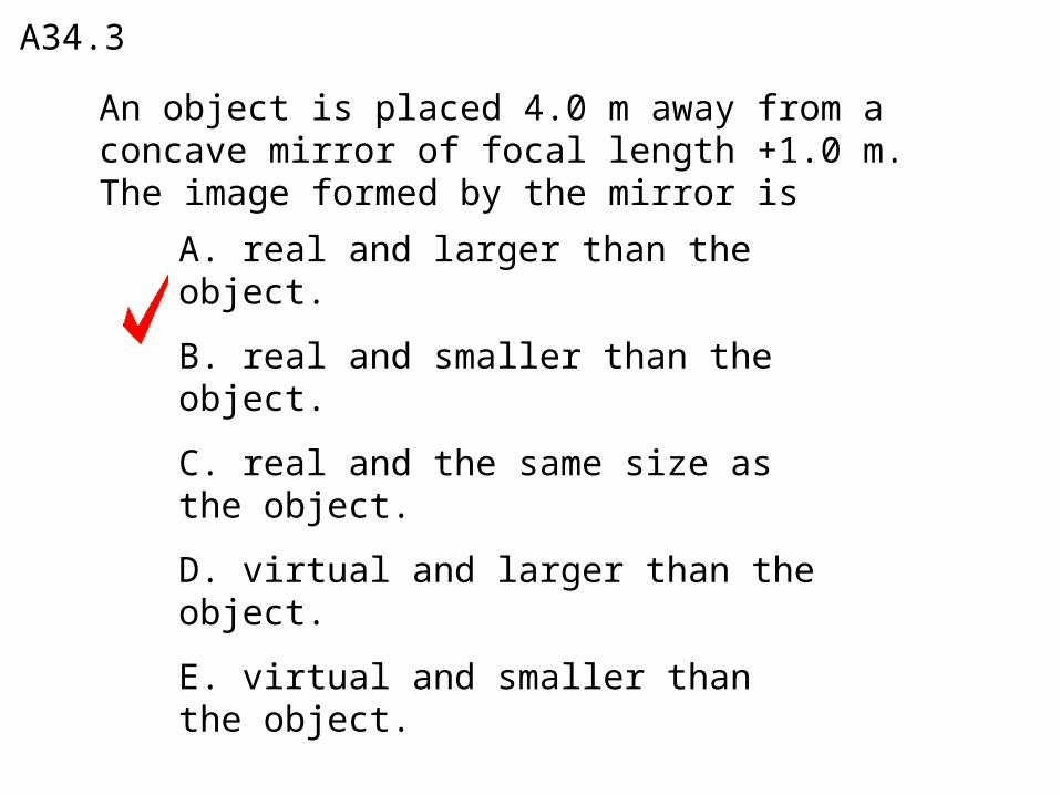
In air this “symmetric biconvex” lens has f = 10 cm.What is its focal length in a medium with n = 1.25?
a) 5 cm
b) 10 cm
c) 20 cm
d) ∞
In air this “symmetric biconvex” lens has f = 10 cm.What is its focal length in a medium with n = 1.25?
a) 5 cm
b) 10 cm
c) 20 cm
d) ∞

In air this “symmetric biconvex” lens has f = 10 cm.What is its focal length in a medium with n = 2?
a) 5 cm
b) -10 cm
c) -20 cm
d) ∞

In air this “symmetric biconvex” lens has f = 10 cm.What is its focal length if the right side is in water (on
the side of a fish tank, for example. nw = 1.33)
a) 5 cm
b) 10 cm
c) 16.6 cm
d) It doesn’t have one focal length

Ray tracing for lenses
Same rule as for mirrors.
Which of the following changes its focal length when it is immersed in water?
Q34.1
A. a concave mirror
B. a convex mirror
C. a diverging lens
D. all of the above
E. none of the above

Which of the following changes its focal length when it is immersed in water?
A34.1
A. a concave mirror
B. a convex mirror
C. a diverging lens
D. all of the above
E. none of the above

Q34.8
A. only the object’s upper half will be visible in the image.
B. only the object’s lower half will be visible in the image.
C. only the object’s left-hand half will be visible in the image.
D. only the object’s right-hand half will be visible in the image.
E. the entire object will be visible in the image.
An object PQ is placed in front of a converging lens, forming a real image P´Q´. If you use black paint to cover the lower half of the lens,

A34.8
A. only the object’s upper half will be visible in the image.
B. only the object’s lower half will be visible in the image.
C. only the object’s left-hand half will be visible in the image.
D. only the object’s right-hand half will be visible in the image.
E. the entire object will be visible in the image.
An object PQ is placed in front of a converging lens, forming a real image P´Q´. If you use black paint to cover the lower half of the lens,

An image of an image• Figure 34.39
Note where rays bend in ray tracing!!

If I move lens B so that it is closer to A than the image formed by A, then:
a) There will be a virtual final imageb) There will be real final imagec) There will be no final image
How do you trace rays for a virtualobject?

Cameras
• Figure 34.40 below shows the key elements of a digital camera.
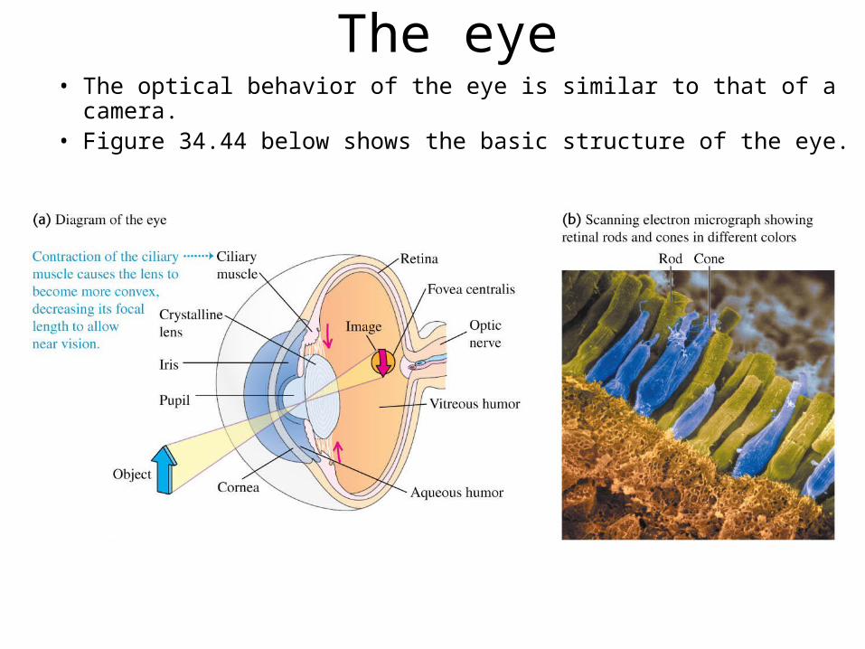
The eye• The optical behavior of the eye is similar to that of a camera.• Figure 34.44 below shows the basic structure of the eye.

Defects of vision• The near point typically recedes with
age, as shown in Table 34.1.• Figure 34.45 (at right) shows a
normal, a myopic, and a hyperopic eye.

Farsighted correction• Figure 34.46 below shows how to correct a hyperopic
(farsighted) eye using a converging lens.
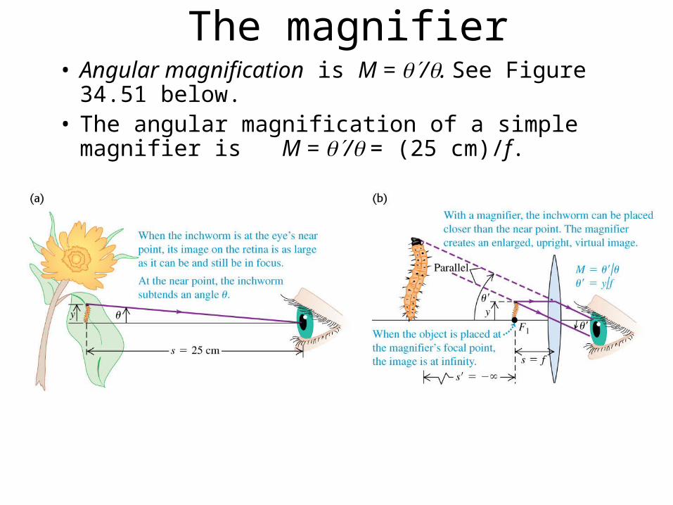
The magnifier• Angular magnification is M = /. See Figure 34.51
below.• The angular magnification of a simple magnifier is M
= / = (25 cm)/f.
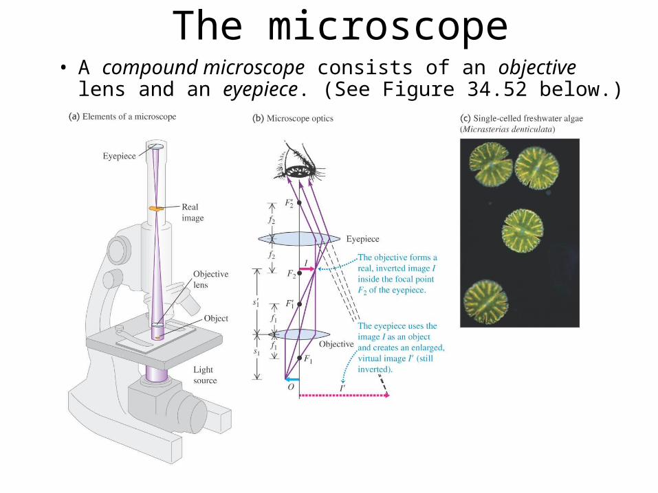
The microscope• A compound microscope consists of an objective lens and an
eyepiece. (See Figure 34.52 below.)

The astronomical telescope• Figure 34.53 below shows the the optical system of an
astronomical refracting telescope.

The reflecting telescope• Figure 34.54 below shows three designs for reflecting telescopes. Part (d)
shows the Gemini North telescope, which uses the design in (c) with an objective mirror 8 meters in diameter.

Chapter 35Interference

Goals for Chapter 35• To consider interference of waves in space
• To analyze two-source interference of light - using phasors!
• To calculate the intensity of interference patterns - using phasors!
• To understand interference in thin films

Introduction– Why do soap bubbles
show vibrant color patterns, even though soapy water is colorless?
– What causes the multicolored reflections from DVDs?
– We will now look at optical effects, such as interference, that depend on the wave nature of light.

Wave fronts from a disturbance– Figure 35.1 at the right
shows a “snapshot” of sinusoidal waves spreading out in all directions from a source.
– Superposition principle: When two or more waves overlap, the resultant displacement at any instant is the sum of the displacements of each of the individual waves.

Constructive and destructive interference
– Figure 35.2 at the right shows two coherent wave sources.
– Constructive interference occurs when the path difference is an integral number of wavelengths.
– Destructive interference occurs when the path difference is a half-integral number of wavelengths.

Two-source interference of light• Figure 35.5 below shows Young’s double-slit experiment with
geometric analysis.

Phasors - a graphical representation of a sinsoidal light
wave at a point in space
Works because cosine is the projection of a radius vector onto
the x-axis.

Interference from two slits
• Figure 35.6 at the right is a photograph of the interference fringes from a two-slit experiment.

Two-slit interference• What is the wavelength of this light?

Broadcast pattern of a radio station• Constructive: crests & troughs line up
• Destructive: crest of S1 is at trough of S2

Intensity in interference patterns
• Find E from Trig• I is proportional to E2
![Handing in Work through Moodle - static.packt-cdn.com€¦ · Handing in Work through Moodle [2 ] Handing in the work Work can be handed in through Moodle using the assignment activity](https://img.pdfslide.us/doc/110x75/5f5b97f185bad95a9b198c03/handing-in-work-through-moodle-handing-in-work-through-moodle-2-handing-in.jpg)