Embed Size (px)
Citation preview
MASTERLINE SERIES CAP200 Page 1 of 46 REV H JUNE 2017
___________________ ___________________ Model Serial # Please have your unit’s model and serial number ready when calling for service. The model # is found on the tank decal and the serial number is located on the compressor nameplate. For all air compressor support requests, please contact your local distributor. Distributer Name: ________________________________________ ________________________________________ Distributer Phone: ________________________________________ Address: ________________________________________ ________________________________________ ________________________________________ ________________________________________ FS Curtis, Inc. Visit us at our website www.fscurtis.com

CAP200 REV H JUNE 2017
ML Series PRESSURE LUBRICATED RECIPROCATING AIR COMPRESSOR
Installation and Operations Manual

MASTERLINE SERIES CAP200 Page 2 of 46 REV H JUNE 2017
Table of Contents
Read Me First Section 1 Safety Precautions ............................................................................................. 3-4 System Diagram ................................................................................................ 5-7
Installation Section 2 Receiving .............................................................................................................. 8 Freight Damage .................................................................................................... 9 Installation Procedure .................................................................................... 10-14 Post Installation Checklist ................................................................................... 15 Electrical Requirements ...................................................................................... 16
Wiring Diagrams Section 3 Simplex, 1 phase and 3 phase ............................................................................ 17 Duplex, dual source ....................................................................................... 18-19 Large Industrial with Solenoid Valve ................................................................... 20 Large Industrial, Fully Packaged ......................................................................... 21 Large Industrial with Pilot Valve .......................................................................... 22 ASSD Control .................................................................................................... 23 Dual Control ........................................................................................................ 24 Ultra Pack 5hp – 7.5hp ....................................................................................... 25 Ultra Pack 10hp – 30hp ...................................................................................... 26
Start Up Section 4 Pre-Start Check List ............................................................................................ 27 Start-Up Procedure ............................................................................................. 28 Operating Modes ........................................................................................... 29-30
Maintenance Section 5 Shut Down Procedure ......................................................................................... 31 Maintenance Schedule ....................................................................................... 32 Oil ....................................................................................................................... 33 Oil Pressure (C200 and up) ................................................................................ 34 Low Oil guard (D96, C79, D97, C89, C98, C100) ............................................... 35 Bolt Torques .................................................................................................. 36-37 Belt Tension ................................................................................................... 38-39 Pilot Valve ........................................................................................................... 40 Bearings .............................................................................................................. 41 Maintenance Parts List ....................................................................................... 41
Troubleshooting Section 6 Troubleshooting Guide ................................................................................... 42-43 Maintenance Check-off Lists .......................................................................... 44-45

MASTERLINE SERIES CAP200 Page 3 of 46 REV H JUNE 2017
READ ME FIRST Safety Precautions The owner, lessor or operator of any compressor unit manufactured by FS Curtis, Inc. is hereby warned that failure to observe all safety precautions may result in serious injury of personnel and/or damage to property. FS Curtis, Inc. neither states as fact, nor in any way implies that this list of safety precautions is an all-inclusive list, the observance of which will prevent all damage to property or injury to personnel. Every reasonable effort has been taken to ensure that complete and correct instructions have been included in this manual. However, possible updates and changes may have occurred since this printing. FS Curtis, Inc. reserves the right to change specifications, without incurring any obligation for equipment previously or subsequently sold. Compressors and/or units are assembled to comply with the customer’s purchase order and in compliance with FS Curtis, Inc. specifications; alteration must not be made to the compressor or unit without FS Curtis’ written approval.
DANGER!
Air used for breathing or food processing must meet O.S.H.A 29 C.F.R. 1910.134 or F.D.A. 21 C.F.R. 178.350 regulations. Failure to do so will cause severe injury or death. WARNING!
Compressors are precision high-speed mechanical equipment requiring caution in operation to minimize hazard to property and personnel. Listed below are some safety precautions that must be observed.
Use of FS Curtis Compressors to transfer toxic, radioactive, flammable, or explosive substances is prohibited.
Do not install the compressor in an area where there is a risk of exposure to explosive gases or combustible dusts, such as flours, starches, coke, coal dust, etc. or in close proximity to corrosive substances.
Release all air pressure from the system before working on the unit and red tag all electrical control switches.
On base mounted units with no receiver tank, the installation of safety valves in the discharge line is the responsibility of the end user. Failure to install safety valves in the discharge line could cause property damage, injury and / or loss of life.
Do not operate compressors on a shipping skid or any other unapproved mounting surfaces.
Do not by-pass motor over-current protection.
Do not change the setting or in any way affect the operation of the safety valves.

MASTERLINE SERIES CAP200 Page 4 of 46 REV H JUNE 2017
Turn off and lockout/tagout the main power disconnect switch before attempting to work or perform any maintenance.
Do not attempt to service any part of this unit while it is running.
Ensure that service personnel are properly trained before attempting to service any part of the electrical system.
Do not operate the unit with any of its safety guards, shields or screens removed.
Do not remove or paint over any DANGER!, WARNING!, CAUTION!, or instructional materials attached to the compressor. Lack of information regarding hazardous conditions can cause property damage or personal injury.
Do not change the pressure setting of the pressure relief valve, restrict the function of the pressure relief valve, or replace the pressure relief valve with a plug.
Do not install a shutoff valve in the compressor discharge line without first installing a pressure relief valve of proper size and design between the shutoff valve and the compressor.
Do not use plastic pipe, unapproved rubber hose, or lead-tin soldered joints in any part of the compressed air system.
Alterations must not be made to this compressor without FS Curtis’ expressed, written approval.
Do not operate the compressor in excess of the A.S.M.E. pressure vessel rating for the receiver or the service rating of the compressor, whichever is lower.
Surface temperatures can exceed 400 °F, power off the unit and allow it to cool before touching any surface of the compressor.
Provisions should be made to have the instruction manual readily available to the operator and maintenance personnel. If for any reason any part of the manual becomes illegible or the manual is lost, contact your local distributor.
Your State and/or local OSHA regulations may require a Pressure Vessel Permit to operate this equipment. Obtaining a permit is the sole responsibility of the owner, lessor or operator of the equipment. Contact your State/Local OSHA for more information.

MASTERLINE SERIES CAP200 Page 5 of 46 REV H JUNE 2017
System Diagram Simplex Units
1
2
3
4
5
6
Air Intake
Air Compressor
Intercooler
Magnetic Starter
Pressure Switch
Vibration Pads with
hardware mounts
Exact orientation of system components
may vary. Please see your model's generalarrangement diagram for a precise
configuration of system components.
4
5
6
12
3
Fig. (1) Simplex, two stage air compressor process.
FS Curtis manufactures a broad array of compressor configurations to satisfy the needs of our diverse customer base. Despite this diversity, all FS Curtis two stage compressor configurations work off the same basic cycle. Air is drawn into the compressor through the air intake and filter assembly. The air enters the first stage, a low pressure chamber where it is compressed the first time. As air is compressed, its temperature increases, this hot air then enters the intercooler where the temperature is reduced. Next, the cooled air enters the second stage, a high pressure chamber where the air is compressed a second time to even higher pressures and discharged into the tank. An Ultra Pack option can be purchased with an installed air-cooled after-cooler which, after the second compression stage, cools the air to a 20°F approach temperature before being stored in the tank. When the compressor has filled the tank to its pressure rating, the pressure switch disengages which turns off the motor, preventing the tank from over pressurizing. Finally, the tank has a ball valve which is opened or closed by the operator and lets air out of the tank, the ball valve is depicted in Fig (1) in the “open” position.

MASTERLINE SERIES CAP200 Page 6 of 46 REV H JUNE 2017
Duplex Units
Air Compressor
1
2
3
4
5
6
Air Intake
Intercooler
Alternator
Pressure Switch
Vibration Isolator Pads
Exact orientation of your system's
components may be different from thelayout in the figure. Please see your
model's general arrangement for a
precise configuration of system
components.
11 223 345 5
Fig. (2) Duplex unit system diagram.
Refer to the simplex diagram for a description of the compression cycle. Duplex units operate in much the same way as simplex units, only there are two compressors. The key difference is in the pressure switch and starter. In a duplex unit, there are two pressure switches, a “lead” pressure switch and a “lag” pressure switch set 10 psi lower than the lead switch. The alternator utilizes both compressors to fill the tank. Once the tank approaches the cutoff “lag” pressure, the alternator selects one compressor to be the “lag” compressor and cycles it off, using only the “lead” compressor to provide the remaining pressure. The alternator then cycles between both compressors, switching the “lead” and “lag” compressor and ensuring roughly equal wear between them. If air usage exceeds the output of a single compressor, the alternator utilizes both the “lead” and the “lag compressor to fulfill operating conditions, once again cycling off the “lag” compressor when its cutoff pressure is reached.

MASTERLINE SERIES CAP200 Page 7 of 46 REV H JUNE 2017
Large Industrial
1
2
3
4
1
2
3
4Air Intake
Air Compressor
Intercooler
Electric Motor Exact orientation of your system's
components may vary. Factory
installed options not shown.
Please see your model's general
arrangement for a precise
configuration of systemcomponents.
Note: Single stage compressors
do not have an intercooler.
Fig (3). Base mounted large industrial units.
Base mounted Large Industrial compressors are capable of outing large amounts of air at high pressures and come in single stage, two stage, or high pressure varieties. They work off the same basic compressor cycle that tank mounted units operate on. NOTE: As these units do not come with a receiver tank, the installation of safety valves in the discharge line is the responsibility of the end user.
MASTERLINE SERIES CAP200 Page 8 of 46 REV H JUNE 2017
INSTALLATION
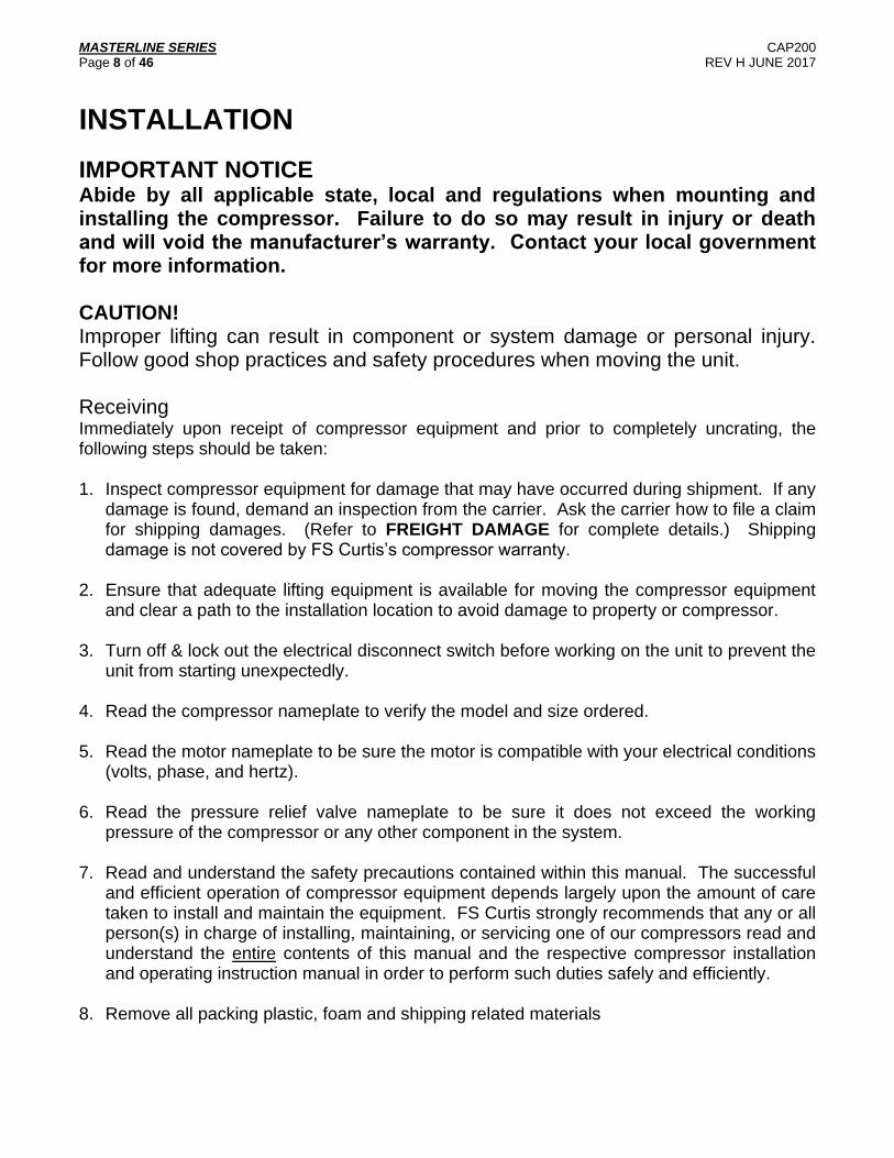
IMPORTANT NOTICE Abide by all applicable state, local and regulations when mounting and installing the compressor. Failure to do so may result in injury or death and will void the manufacturer’s warranty. Contact your local government for more information. CAUTION! Improper lifting can result in component or system damage or personal injury. Follow good shop practices and safety procedures when moving the unit. Receiving Immediately upon receipt of compressor equipment and prior to completely uncrating, the following steps should be taken: 1. Inspect compressor equipment for damage that may have occurred during shipment. If any
damage is found, demand an inspection from the carrier. Ask the carrier how to file a claim for shipping damages. (Refer to FREIGHT DAMAGE for complete details.) Shipping damage is not covered by FS Curtis’s compressor warranty.
2. Ensure that adequate lifting equipment is available for moving the compressor equipment
and clear a path to the installation location to avoid damage to property or compressor.
3. Turn off & lock out the electrical disconnect switch before working on the unit to prevent the unit from starting unexpectedly.
4. Read the compressor nameplate to verify the model and size ordered.
5. Read the motor nameplate to be sure the motor is compatible with your electrical conditions
(volts, phase, and hertz).
6. Read the pressure relief valve nameplate to be sure it does not exceed the working pressure of the compressor or any other component in the system.
7. Read and understand the safety precautions contained within this manual. The successful
and efficient operation of compressor equipment depends largely upon the amount of care taken to install and maintain the equipment. FS Curtis strongly recommends that any or all person(s) in charge of installing, maintaining, or servicing one of our compressors read and understand the entire contents of this manual and the respective compressor installation and operating instruction manual in order to perform such duties safely and efficiently.
8. Remove all packing plastic, foam and shipping related materials

MASTERLINE SERIES CAP200 Page 9 of 46 REV H JUNE 2017
FREIGHT DAMAGE
The transportation industry has adopted a modification with regard to the handling of obvious and concealed damage claims. Therefore, it is extremely important that you examine every carton and crate as soon as you receive it. If there is any obvious damage to the shipping container, have the delivering carrier sign the freights bill, noting the apparent damage, and request a damage report. If concealed damage is discovered at a later date, the carrier must be notified within 15 days of initial receipt of freight. Contact the carrier as soon as possible, giving them an opportunity to inspect the shipment at the premises where the original delivery was made. Retain all containers and packing for inspection by the carrier. Do not move the freight. Concealed shipping damage is not covered by the FS-Curtis warranty.
A claim form can be requested from the carrier. Your claim will need to be substantiated with the following documents.
Original bill of lading Original paid freight bill Original invoice or certified copy Other particulars obtainable in proof of loss or damage (photos, damage inspection
report, etc.)
We suggest these instructions be circulated to your shipping and receiving personnel.

MASTERLINE SERIES CAP200 Page 10 of 46 REV H JUNE 2017
Installation Procedure Step 1 – Select a proper location for installation Select a clean, dry, well lit area with a rigid floor strong enough to support the compressor and with adequate ventilation. Avoid placement of the compressor in an area that is excessively hot, dusty, humid or contaminated with foreign gases such as ammonia or acid fumes. The unit should never be operated at ambient temperatures above 104°F or below 32°F. If the ambient temperature is below 40°F, FS Curtis recommends using Arctic oil. Maintenance checks are required daily, thus three (3) feet of space needs to be provided around the compressor for proper inspection. Note – If the unit or air intake is to be located outdoors, please contact your local distributor for additional instructions. Step 2 – Remove the skid Remove and discard the shipping skid. The compressor should NEVER be operated on a skid. Step 3 – Prepare the mounting surface See Fig. (3) and Fig. (4) for a tank mounted bolt pattern and prepare the surface accordingly. See Table (2) for base mounted bolt patterns. See Table (3) for acceptable installation methods
B
A
D
Fig. (4) Horizontal bolt hole pattern Fig. (5) Vertical bolt hole pattern
Horizontal Tank (gallons)
A (in)
B (in)
Base Hole Size (in)
Recommended Bolt Diameter (in)
Vertical Tank (gallons)
D (in)
Hole Size (in)
Recommended Bolt Diameter (in)
30 17.75 23 9/16 1/2" 80 22.5 11/16 5/8”
80 17.75 40 9/16 1/2” 120 26.375 11/16 5/8”
120 22 40 9/16 1/2”
200 28 40 3/4 5/8”
240 40 54 3/4 5/8” Table (1) Bolt hole mounting patterns for various tank sizes.
MASTERLINE SERIES CAP200 Page 11 of 46 REV H JUNE 2017
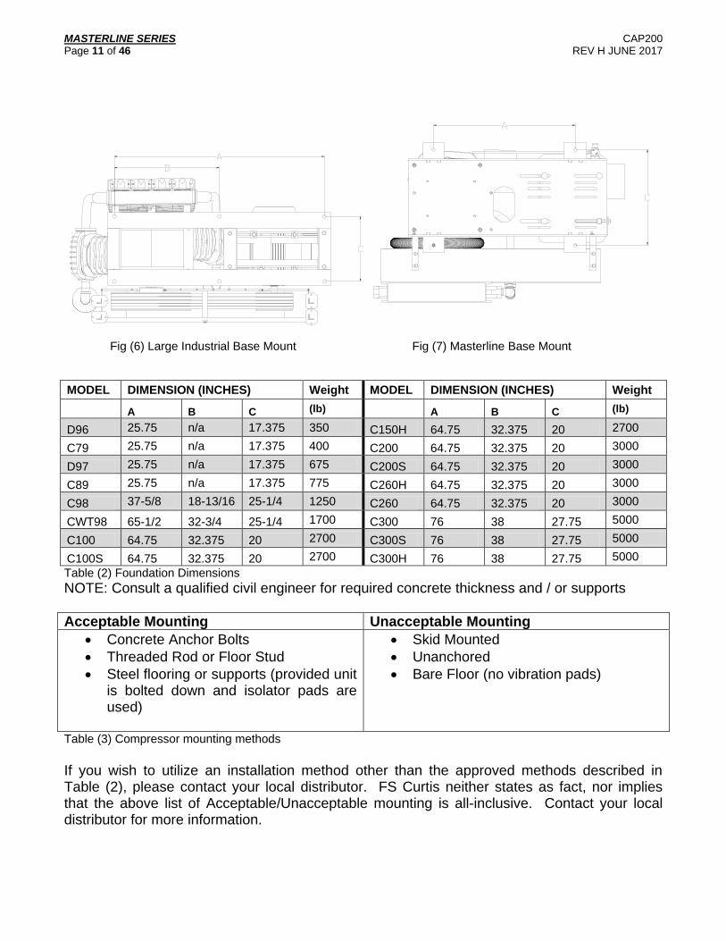
Fig (6) Large Industrial Base Mount Fig (7) Masterline Base Mount
MODEL DIMENSION (INCHES) Weight MODEL DIMENSION (INCHES) Weight
A B C (lb) A B C (lb)
D96 25.75 n/a 17.375 350 C150H 64.75 32.375 20 2700
C79 25.75 n/a 17.375 400 C200 64.75 32.375 20 3000
D97 25.75 n/a 17.375 675 C200S 64.75 32.375 20 3000
C89 25.75 n/a 17.375 775 C260H 64.75 32.375 20 3000
C98 37-5/8 18-13/16 25-1/4 1250 C260 64.75 32.375 20 3000
CWT98 65-1/2 32-3/4 25-1/4 1700 C300 76 38 27.75 5000
C100 64.75 32.375 20 2700 C300S 76 38 27.75 5000
C100S 64.75 32.375 20 2700 C300H 76 38 27.75 5000
Table (2) Foundation Dimensions
NOTE: Consult a qualified civil engineer for required concrete thickness and / or supports
Acceptable Mounting Unacceptable Mounting
Concrete Anchor Bolts
Threaded Rod or Floor Stud
Steel flooring or supports (provided unit is bolted down and isolator pads are used)
Skid Mounted
Unanchored
Bare Floor (no vibration pads)
Table (3) Compressor mounting methods
If you wish to utilize an installation method other than the approved methods described in Table (2), please contact your local distributor. FS Curtis neither states as fact, nor implies that the above list of Acceptable/Unacceptable mounting is all-inclusive. Contact your local distributor for more information.

MASTERLINE SERIES CAP200 Page 12 of 46 REV H JUNE 2017
Step 4 – Install Vibration Isolator pads and mount the compressor Exposure to excessive vibrations can significantly shorten the life of the compressor. FS Curtis highly recommends mounting the unit on vibration isolator pads and the compressor should NEVER be operated without being securely fastened to the ground. Using a level, please check for proper alignment of the compressor. Uneven installation will unbalance the compressor leading to excessive noise, vibrations, and wear. Place a steel shim between the concrete and vibration pads and shim down as necessary for leveling. Level the compressor so it can be bolted down securely. Before tightening the bolts, check to see that all four feet are resting on the foundation. See fig (5) for mounting instructions for a floor stud, and see fig (6) for mounting instructions for an anchor bolt.
FLANGE NUTLeave loose & lockwith a back-up nut
RECEIVER FOOT
ISOLATOR BACKINGPLATE OR SHIMS IFNECESSARY
ISOLATOR
ANCHOREDFLOORSTUD
FLANGE NUTLeave loose & lockwith a back-up nut
RECEIVER FOOT
ISOLATOR BACKINGPLATE OR SHIMS IFNECESSARY
ISOLATOR
ANCHOREDFLOORSTUD
Fig. (8) Anchored Floor Stud installation

MASTERLINE SERIES CAP200 Page 13 of 46 REV H JUNE 2017
Recommended Installation – Use concrete anchor bolt
12
34
56
78
Fig. (9) Recommended Installation Method
1 Mounting bolt, see Table (3) for recommended sizes
2 Flat washer, sized for bolt
3 Compressor Base
4 Vibration Isolator Pads
5 Steel Shim (as necessary for leveling)
6 Concrete floor, see local codes for recommended concrete thickness and hole drilling depth
7 Heavy duty double expansion machine bolt anchor shield
8 1” diameter hole
Table (4) Anchor Bolt specifications

MASTERLINE SERIES CAP200 Page 14 of 46 REV H JUNE 2017
Step 5 – Tighten the fasteners Incrementally tighten the mounting bolts evenly in a cross pattern. If necessary, after start up, continue incrementally tightening the mounting bolts in a crossing pattern until vibrations have been reduced to an acceptable level. After vibrations have been minimized, loosen ONE mounting bolt. The unit expands and contracts with changes in temperature, leaving ONE bolt loosened will allow for thermal expansion of the unit, reducing thermal stresses and vibrations on the tank. If after loosening one bolt the vibrations get worse, retighten bolt and select a different unit. Excessive vibrations can damage equipment. Step 6 – Install discharge piping network Run a clean pipe to the tank discharge opening, bushing up or down as necessary with clean bushings and fittings. Note that the more bushings and fittings placed in the air distribution system, the greater the opportunity for air leaks and breaks. FS Curtis recommends the installation of drip legs in the distribution line. Always install a safety relief valve in the distribution line between the compressor unit and in-line shutoff valves. If more than one compressor pumps into a common system, a check valve in the distribution line of each compressor unit is recommended to prevent moisture from entering the cylinder head(s) when one compressor is idle. A globe or gate valve (WOG rated) installed in the discharge line will allow compressor isolation from plant air system for compressor maintenance. (Note: A safety relief valve should be located between the compressor and the globe/gate valve.) Step 7 – Install Compressor Intake (IF APPLICABLE) If the compressor intake is to be located away from the unit, please use the following instructions to ensure safe and efficient operation. Run a clean pipe to the compressor suction opening, bushing up or down as necessary with clean bushings and fittings. Note that the more bushings and fittings placed in the intake line, the greater opportunity for air leaks and breaks. If the run is over 10 feet in length, use a larger pipe diameter to avoid excessive pressure drops. When installing the pipes, please pitch the piping down and slightly away from the intake, to ensure that debris and condensation drains away from the compressor. Step 8 – Install APU Compressor Intake (APU Base mounted units with no tank) Run piping between the air receiver and the air compressor’s head unloaders. The air receiver must be located a minimum of 10 feet away for large industrial compressors to avoid pulsations in the air signal. If the APU receives its air signal from the discharge line, or if the tank is located too close to the compressor, then the pulsations will cause the compressor to load and unload erratically. Note piping must be pitched down and away from the compressor or moisture will backflow to the compressor, dilute the lubricant, and cause serious damage to the unit. The installation of drain pipes, drip legs or moisture separators is highly encouraged.
CAUTION! Piping the air pressure unloader to the discharge line will lead to excessive pulsations that will cause the machine to load and unload erratically.

MASTERLINE SERIES CAP200 Page 15 of 46 REV H JUNE 2017
Post Installation Checklist
WARNING! Failure to perform the post installation checklist may result in mechanical failure, property damage, serious injury or even death.
Steps 1 through 9 should be performed prior to connecting the unit to a power source. If any condition on the checklist is not satisfied, make the necessary adjustments or corrections before starting the compressor. 1. Remove all installation tools from the compressor and check for installation debris.
Abrasive dust can seriously damage the air intake and belt assemblies. 2. All FS Curtis compressors are shipped from the factory filled with the required amount of
Curtis Lube Plus Compressor Lubricant specially formulated for Curtis Compressors. The oil level should register in the center of the oil sight glass or between the high and low marks on the dipstick. For additional lubricant contact your authorized Curtis distributor. Failure to use authorized lubricant will void the manufacturer’s warranty.
3. Check inlet-piping installation. 4. Check all pressure connections for tightness. 5. Make sure all pressure relief valves in the air distribution are correctly installed. 6. Make sure all guards are in place and securely mounted. 7. Open all manual shutoff valves at and beyond the compressor and tank discharges.
8. Check and tighten all connections (mechanical and electrical) as they may have loosened
during shipment 9. After all the above conditions have been satisfied, the unit can be connected to the proper
power source.

MASTERLINE SERIES CAP200 Page 16 of 46 REV H JUNE 2017
Electrical Requirements TANK MOUNTED UNITS The electrical installation of this unit should only be performed by a qualified electrician with knowledge of the National Electrical Code (N.E.C.), O.S.H.A. code and/or any local or state codes having precedence.
All FS Curtis tank-mounted compressors come with a factory installed, pre-wired starter, if you wish to provide your own starter, please contact your local distributor for more information. Check the electrical supply for voltage, phase, and frequency to see that they match the nameplate stampings on the motor, magnetic starter, solenoids, and other controls. Before attempting to service electrical systems, ensure that maintenance personal are properly qualified, and service procedures comply with NFPA 70-2008, National Electrical Code, National Electrical Safety Code, as well as any applicable state and local regulations. Failure to abide by the national, state and local codes may result in physical harm and/or property damage and will void the manufacturer’s warranty.
DANGER! High voltage may cause personal injury or death, per O.S.H.A. regulations 1910.137, disconnect and lockout/tagout all electrical power supplies before opening the electrical enclosure or servicing.
WARNING! Never assume a compressor is safe to work on just because it is not currently operating. It could restart at any time. Follow all safety precautions outlined in the Safety Precautions section. NEMA electrical enclosures and components must be appropriate to the area installed. Safety and efficiency are the primary concerns when selecting components for compressed air systems. Products of inferior quality can not only hinder performance of the unit, but could cause system failures that result in bodily harm or even death. Select only top quality components for your system. Call your local FS Curtis Distributor for quality parts and professional advice.
CAUTION! Turn off and lockout/tagout the main power disconnect switch before attempting to install the unit. NOTE: At installation, the customer is to provide disconnect, branch circuit over-current protection, and grounding between the power supply and the electrical control enclosure in accordance with the National Electric Code and/or any local codes.

MASTERLINE SERIES CAP200 Page 17 of 46 REV H JUNE 2017
Wiring Diagrams: Simplex Single Phase and 3 Phase
TURN OFF / TAGOUT POWER BEFORE SERVICING
3
2
1
5
4
Fig. (10) Simplex Starter
95 96
OL
Pressure
Switch
Power Supply
to L1 and L2
MS1
Motor
Jumper T2 to L3
M
L2
L3
L1OL
A2A1
T3T2T1
95 96
OL
Pressure
Switch
Power Supply to
L1, L2, and L3
MS1
Motor
M
L2
L3
L1OL
A2A1
T3T2T1
Fig (11) Single Phase wiring diagram Fig (12) Three phase wiring diagram NOTE: The above wiring diagrams are valid for standard models only. Contact your local distributor for wiring diagrams for factory installed options
1 L1
2 L2
3 L3
4 Overload relay
5 Reset switch

MASTERLINE SERIES CAP200 Page 18 of 46 REV H JUNE 2017
Wiring Diagrams: Duplex Dual Source Alternator
TURN OFF / TAGOUT POWER BEFORE SERVICING
1
2
3
1
2
3
Fig. (13) Duplex dual source alternator panel.
NOTE: See Following page for Duplex Wiring Diagram.
1 L1
2 L2
3 L3
MASTERLINE SERIES CAP200 Page 19 of 46 REV H JUNE 2017
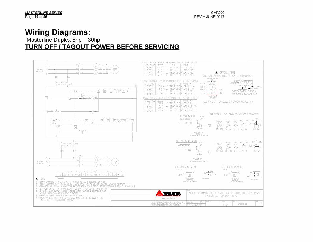
Wiring Diagrams: Masterline Duplex 5hp – 30hp
TURN OFF / TAGOUT POWER BEFORE SERVICING

MASTERLINE SERIES CAP200 Page 20 of 46 REV H JUNE 2017
Wiring Diagrams: Large Industrial with Solenoid Valve 50hp – 125hp
TURN OFF / TAGOUT POWER BEFORE SERVICING

MASTERLINE SERIES CAP200 Page 21 of 46 REV H JUNE 2017
Wiring Diagrams: Large Industrial with Solenoid Valve, Fully Packaged 50hp – 125hp
TURN OFF / TAGOUT POWER BEFORE SERVICING

MASTERLINE SERIES CAP200 Page 22 of 46 REV H JUNE 2017
Wiring Diagrams: Large Industrial with Pilot Valve 50hp – 125hp
TURN OFF / TAGOUT POWER BEFORE SERVICING

MASTERLINE SERIES CAP200 Page 23 of 46 REV H JUNE 2017
Wiring Diagrams: ASSD and Solenoid Valve: 5hp – 40hp
TURN OFF / TAGOUT POWER BEFORE SERVICING
MASTERLINE SERIES CAP200 Page 24 of 46 REV H JUNE 2017
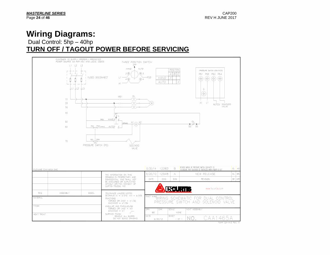
Wiring Diagrams: Dual Control: 5hp – 40hp
TURN OFF / TAGOUT POWER BEFORE SERVICING

MASTERLINE SERIES CAP200 Page 25 of 46 REV H JUNE 2017
Wiring Diagrams: Ultra Pack 5hp – 7.5hp
TURN OFF / TAGOUT POWER BEFORE SERVICING
MASTERLINE SERIES CAP200 Page 26 of 46 REV H JUNE 2017
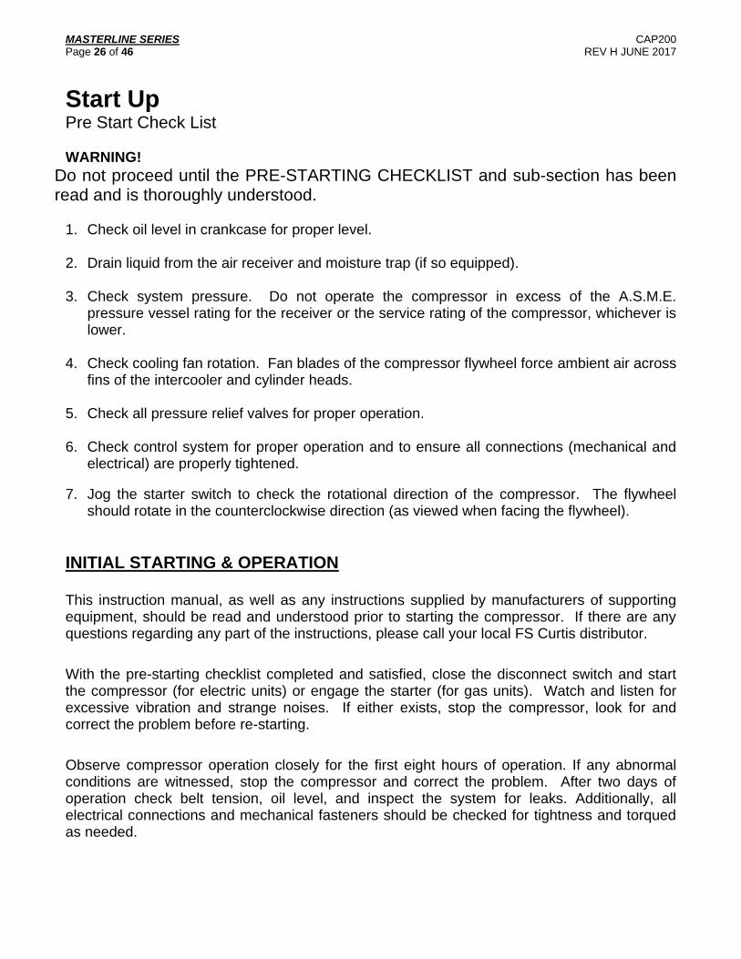
Start Up Pre Start Check List WARNING!
Do not proceed until the PRE-STARTING CHECKLIST and sub-section has been read and is thoroughly understood.
1. Check oil level in crankcase for proper level.
2. Drain liquid from the air receiver and moisture trap (if so equipped). 3. Check system pressure. Do not operate the compressor in excess of the A.S.M.E.
pressure vessel rating for the receiver or the service rating of the compressor, whichever is lower.
4. Check cooling fan rotation. Fan blades of the compressor flywheel force ambient air across
fins of the intercooler and cylinder heads. 5. Check all pressure relief valves for proper operation. 6. Check control system for proper operation and to ensure all connections (mechanical and
electrical) are properly tightened.
7. Jog the starter switch to check the rotational direction of the compressor. The flywheel should rotate in the counterclockwise direction (as viewed when facing the flywheel).
INITIAL STARTING & OPERATION This instruction manual, as well as any instructions supplied by manufacturers of supporting equipment, should be read and understood prior to starting the compressor. If there are any questions regarding any part of the instructions, please call your local FS Curtis distributor.
With the pre-starting checklist completed and satisfied, close the disconnect switch and start the compressor (for electric units) or engage the starter (for gas units). Watch and listen for excessive vibration and strange noises. If either exists, stop the compressor, look for and correct the problem before re-starting.
Observe compressor operation closely for the first eight hours of operation. If any abnormal conditions are witnessed, stop the compressor and correct the problem. After two days of operation check belt tension, oil level, and inspect the system for leaks. Additionally, all electrical connections and mechanical fasteners should be checked for tightness and torqued as needed.

MASTERLINE SERIES CAP200 Page 27 of 46 REV H JUNE 2017
START-UP If the compressor is equipped with an automatic start-stop control (with pressure switch unloading), it is automatically unloaded upon starting, and will automatically load after attaining running speed. Simply throw the power switch to start the unit.
For engine driven compressors equipped with a pilot valve, the pilot valve must be manually unloaded prior to starting the compressor.
OPERATING MODES Automatic Start-Stop (ASSD) with Bleeder-Type Pressure Switch Operation A compressor equipped for start-stop operation with a bleeder type pressure switch to provide an automatic unloaded start. When the compressor reaches a predetermined cutoff pressure, the pressure switch contacts open terminating power to the starter coil and open the exhaust port on the pressure switch. Discharge line pressure is then vented to atmosphere. When the cut-in pressure is reached, the pressure switch contacts close completing the control circuit and starting the motor. The electric motor must be started no more than six (6) times per hour to provide adequate motor life. Automatic Start-Stop (ASSD) with Solenoid Valve Piloted Suction Valve Unloading A compressor equipped for ASSD with solenoid valve controls utilizes air pressure unloaders (APU). To provide automatic start-stop operation with an unloaded start on these models, a 3-way solenoid valve with a restricted exhaust and a non-bleeder pressure switch are used to achieve the following sequence of operation. If the compressor shuts down or stops because the pressure switch opens, the solenoid valve is de-energized permitting air pressure from the receiver to act on the unloaders. This unloads the compressor, opening the intake valves, venting the cylinders to atomosphere.
When the compressor is started again or the pressure switch closes, the solenoid valve is energized which permits air from the unloader to exhaust through the restrictor plug. The restrictor plug delays the loading action of the compressor until it has reached operating speed, which reduces torque demand and starting current for the electric motor. Constant Speed Control A compressor unit set up to run continuously has an unloading mechanism to stop the pumping action of the compressor at a predetermined cut-out pressure and start the pumping action at some lower pre-determined cut-in pressure. This unloading cycle is accomplished by holding open the suction valves during the unloading cycle. On the C79 compressor, the low stage suction valve is held open while a by-pass valve unloads the high stage during the unloaded cycle.
These methods employ air pressure from the receiver to actuate unloader pistons which actuate the unloading mechanism. Control of the air pressure to and from the unloaders is accomplished by either an air pressure actuated pilot valve or by a three-way solenoid valve controlled by a pressure switch. During unloaded operation, the motor only draws 15-25% of its normal electrical load.

MASTERLINE SERIES CAP200 Page 28 of 46 REV H JUNE 2017
The unloaders are of “O” ring and piston type with pressure and over travel compensating spring. This in turn contacts the valve which has a built in unloader fork and return spring. To check to see if unloader is stuck open or closed the action can be viewed on the low-pressure cylinders by removing air inlet filter and elbow and watching the operation through the inlet opening. If the piston unloader becomes sticky or jerky in operation, remove the unloader cylinder and piston assembly. Remove all dirt or carbon and lubricate the unloader piston and cylinder with a high temperature bearing grease before re-assembly and installation.
Pilot Valve The pilot valve supplied with certain compressor units is a spring-loaded ball and seat type. When air receiver pressure reaches the pre-set (adjustable) cut-out pressure, the ball is unseated permitting air pressure to actuate the unloaders. When the air receiver pressure drops to the cut-in pressure, the ball reseats and relieves the pressure acting on the unloaders permitting the compressor to pump again.
For engine driven compressors these valves have a manual override device consisting of a cam located at the exposed end of the stem, which forces the stem outward. This permits manual unloading and reloading of the compressor unit. Should these valves become faulty in operation, they may require disassembly and cleaning (especially the filter). After reassembly, the pressure settings (cut-out and cut-in) must be readjusted. Dual Control Operation: Hand Off Auto (HOA) Compressors equipped with the HOA Dual Control feature have the option of running in either Constant Run or Automatic Start Stop depending on air demand. The FS Curtis design utilizes a three way solenoid valve controlled by a selector switch built directly into the starter. Simply change the position of the selector switch to adjust the operation of the compressor. The Auto position stands for Automatic Start Stop, the Hand position stands for Constant Run. Dual Control Operation: Pilot Valve Electric compressors with pilot valves do not have an HOA switch but can still be operated in either start-stop or constant run mode. Turning the knob on top of the pilot valve all the way clockwise will run the unit in start-stop, operated by the bleeder-type pressure switch. Turning the knob all the way counterclockwise will run the unit in continuous run, operated by the pilot valve.

MASTERLINE SERIES CAP200 Page 29 of 46 REV H JUNE 2017
Maintenance For the first weeks, the compressor needs time to “break in.” The belt requires time to stretch and fit into the surface of the pulleys. The piston rings need time to seat themselves into the cylinder walls, and bearings need to wear into place. For the first 100 hours or so, the compressor will consume higher than normal amounts of oil until the break in process is complete.
FIRST MONTH MAINTENANCE Check oil level at the beginning of every week, fill as needed, see oil subsection.
Check belt tension at the beginning of each week and tighten as required, see belt tension subsection.
Check bolts, pulley clamp screws, and jam nuts for tightness. Torque if necessary (see bolt torques subsection)
Shut Down Procedure The following procedures should be followed when stopping the compressor for maintenance or service. WARNING!
Never assume a compressor is safe to work on just because it is not operating. It could start at any time. 1. Per O.S.H.A. regulation 1910.147; The Control of Hazardous Energy Source
(Lockout/Tagout); disconnect and lockout the main power source. Display a sign in clear view at the main power switch that the compressor is being serviced.
2. Isolate the compressor from the compressed air supply by closing the manual shutoff valve
upstream and downstream from the compressor. Display a sign in clear view at the shutoff valve stating that the compressor is being serviced.
3. Lock open a pressure relief valve within the pressurized system to allow the system to be
completely de-pressurized. NEVER remove a plug to relieve the pressure. 4. Open all manual drain valves within the area to be serviced. 5. Wait for the unit to cool before starting to service. (Temperatures of 125°F can burn skin.
Some surface temperatures exceed 350°F when the compressor is operating.

MASTERLINE SERIES CAP200 Page 30 of 46 REV H JUNE 2017
Maintenance Schedule
To assure maximum performance and service life of your compressor, a routine maintenance schedule should be developed. A sample schedule has been included to help you develop a maintenance schedule designed for your particular application. Time frames may need to be shortened in harsher environments or during periods of extremely heavy use. Make copies of this checklist and retain copy of the checklist, enter dates and maintenance person’s initials in the appropriate spaces. Makes copies of this checklist and retain copies of the completed checklists for potential warranty purposes. Enter the dates and maintenance person’s initials in the appropriate spaces. Keep the checklist and this Operations Manual readily available near the compressor.
DAILY MAINTENANCE Check oil level. Check oil for discoloration and filth. Drain oil and replace if required.
Drain drip legs and traps in air distribution system.
Open drain cock located at the bottom of the tank to relieve condensation.
Drain intercooler (Large Industrial)
Check for oil leaks.
WEEKLY MAINTENANCE Manually operate the pressure relief valves to be certain they are working.
Clean the cooling surfaces of the intercooler and compressor.
Check the compressor for air leaks.
Check the compressed air distribution system for leaks.
Check Oil Pressure, record reading at oil change (Large Industrials)
MONTHLY MAINTENANCE Check motor belt tension.
Check fan belt tension (C200, C260, and C300).
Check bolt torques, pulley clamp screws, and jam nuts for tightness. Torque if necessary
Inspect entire air distribution system for leaks.
Check all connections (mechanical and electrical) and tighten as necessary.
EVERY THREE MONTHS Change oil (more frequently in harsher environments).
Inspect valves for rust, wear, and carbon build up
Check air filter for cleanliness and replace if necessary
Replace Oil filter and clean oil strainer (Large industrials)
EVERY SIX MONTHS Replace air filter

MASTERLINE SERIES CAP200 Page 31 of 46 REV H JUNE 2017
Oil FS Curtis MasterLine compressors require a break in period and are factory filled with the needed lubricant for the break in period. After the break in period is complete, drain the oil and replace with required oil for your compressor listed below. FS Curtis manufactures two different lubrication systems for Masterline compressors. The compressors D96, D97, C79, C89, C98, and C100 use an oiling ring system. Use ISO68 FSC-1000 Premium Reciprocating Compressor Lubricant. This oil is specially formulated for Curtis Reciprocating Air Compressors and includes non-Detergent type with anti-foam, anti-rust and oxidation inhibitors. Use ISO100 FSC-1000A for break in and regular use if ambient air temperatures exceed 90°F. Large industrial units C200, C260, and C300 have an oil pump system and operate under very high air pressures and temperatures. Use ISO100 FSC-1000A. This oil is blended for FS Curtis large industrial units. For Large Industrials C150H, C260H, and C300H, use ISO100 FSC-1000S synthetic oil. For all other large industrials, use ISO100 FSC-1000A. For proper lubrication the compressor shall not be operated below the minimum or above the maximum R.P.M. recommended for the various models.
1. Maintain oil level mid-way between the upper and lower lines of the crankcase sight gage. Fig. (14) Oil sight glass reading
2. Stop compressor to add and gauge oil. 3. Do not fill above the upper line and do not operate compressor with oil level below the lower line. NOTE: ISO100 FSC-1000S synthetic oil is available as an option on all Masterline Compressors. Using synthetic oil will significantly extend the life of your compressor.
OIL CAPACITIES
MODEL NUMBER
HORSEPOWER (hp)
MIN RPM
MAXIMUM RPM
OIL CAPACITY
D96 5 500 800 4 Pints
C79 7½ 500 900 4 Pints
D97 10 500 800 5 Pints
C89 15 600 950 5 Pints
C98 20-25 500 950 6 Quarts
C100 / C100S 30-40 600 850 4 Gallons
C150H 40-60 600 900 4 Gallons
C200 / C200S 50 600 950 4 ½ Gallons
C260 60 600 950 4 ½ Gallons
C260H 50-60 600 835 4 ½ Gallons
C300 / C300S 75-125 600 950 6 Gallons
C300H 100-125 600 835 6 Gallons
Table (5)
MASTERLINE SERIES CAP200 Page 32 of 46 REV H JUNE 2017
Oil Pressure Large Industrials (C200 and up) Base mounted large industrial units are equipped with a factory installed oil pump and oil pressure gauge. Proper oil pressure readings are as follows
Oil Gauge Pressure Normal Pressure .......................... 26 to 30 PSIG Normal Pressure (C260H) ........... 30 to 40 PSIG Minimum Pressure ....................... 20 PSIG Switch Cutoff Pressure ................ 18 PSIG
Oil Switch The oil pressure safety switch is set and tested at the factory for 18 pounds minimum oil pressure. If the oil pressure is below the set pressure, the safety switch will cause the power to shut off. After correcting the problem, power can be restored by the following procedure:
1. Push reset button on the pressure switch. 2. Push start button on starter.
Oil Pressure Procedure Stop compressor and turn off power, then drain oil from crankcase. When facing flywheel, remove the right hand side door from crankcase to expose closure screw in bearing plate No. CM-836. Remove closure screw – No. CM-843 for models 200, 260, and 260H No. CM-924 for models 300 and 300H Follow the above instructions to expose closure screw. Note: 1/2” dia. Hex hollow head adjusting setscrew with lock nut in the closure screw, see drawing LH-32.
To adjust oil pressure 1. Adjust with ¼” Allen Wrench 2. To increase pressure – turn set screw to the right (tighten). 3. To lower pressure – turn set screw to the left (loosen). Note – under normal conditions one full turn of the set screw will change the oil pressure approximately 4 pounds. Hold set screw position and tighten lock nut. Return side door, restore oil level in crankcase (check oil level) and start compressor. “Note Oil Pressure Gauge” if normal pressure 36 to 40 pounds is not obtained by the above procedure contact factory service department.
MASTERLINE SERIES CAP200 Page 33 of 46 REV H JUNE 2017
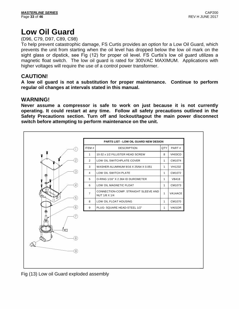
Low Oil Guard (D96, C79, D97, C89, C98) To help prevent catastrophic damage, FS Curtis provides an option for a Low Oil Guard, which prevents the unit from starting when the oil level has dropped below the low oil mark on the sight glass or dipstick, see Fig (12) for proper oil level. FS Curtis’s low oil guard utilizes a magnetic float switch. The low oil guard is rated for 300VAC MAXIMUM. Applications with higher voltages will require the use of a control power transformer.
CAUTION! A low oil guard is not a substitution for proper maintenance. Continue to perform regular oil changes at intervals stated in this manual.
WARNING! Never assume a compressor is safe to work on just because it is not currently operating. It could restart at any time. Follow all safety precautions outlined in the Safety Precautions section. Turn off and lockout/tagout the main power disconnect switch before attempting to perform maintenance on the unit.
1
PARTS LIST - LOW OIL GUARD NEW DESIGN
ITEM # DESCRIPTION QTY PART #
1 10-32 x 1/2 FILLISTER HEAD SCREW 8 VH03CD
2 LOW OIL SWITCHPLATE COVER 1 CM1074
3 WASHER-ALUMINUM 9/16 X 25/64 X 0.051 1 VH1232
4 LOW OIL SWITCH PLATE 1 CM1072
5 O-RING 1/16" X 2.364 ID DUROMETER 1 VB418
6 LOW OIL MAGNETIC FLOAT 1 CM1073
7CONNECTION-COMP. STRAIGHT SLEEVE AND
NUT 1/8 X 1/41 VA14ACE
8 LOW OIL FLOAT HOUSING 1 CM1070
9 PLUG- SQUARE HEAD-STEEL 1/2" 1 VA01DR
2
3
4
5
6
8
7
9
Fig (13) Low oil Guard exploded assembly

MASTERLINE SERIES CAP200 Page 34 of 46 REV H JUNE 2017
Bolt Torques Masterline Compressors
Consult exploded assembly for part #
D96 C79 C89
Size Torque (ft*lb)
Size Torque (ft*lb)
Size Torque (ft*lb)
Head Bolt 3/8-16 25 3/8-16 25 5/8-11UNC x 4 1/2 140
Cylinder to Case 7/16-14 24 7/16-14 24 HHCS 5/8-11UNC x 1 3/4 68
Connecting Rod 3/8-24 28 3/8-24 28 HHCS 3/8-24UNF x 2 3/4 15
Intercooler - - - - - - HHCS 1/2-13UNC x 4 1/2 HHCS 1/2-13UNC x 3 3/4
50
Side Door 5/16-18 7 5/16-18 7 HHCS 3/8-16UNC x 1 1/4 Machine Screw 5/16 x 3/8
13
End Plate 3/8-16 28 3/8-16 28 HHCS 3/8-16UNC 1 1/4 1/4-20 x 1/2 screw
37
Valve Cover - - - - - - 1/2-13UNC X1.5 Nut-Stud
50 15
Valve Hold down Set-Screw
3/8-16 17 3/8-16 17 3/8-16UNC x 1 3/4 17
Unloader APU 1 1/8-12 30 7/8-14 30 7/8-14 50
HP/LP SV Plug - - - - - - Valve Assembly 80
D97 C98
Size
Torque (ft*lb)
Size Torque (ft*lb)
Head Bolt 5/8-11UNC x 4 1/2 140 5/8-11UNC x 4 1/2 140
Cylinder to Case HHCS 5/8-11UNC x 1 3/4 68 HHCS 5/8-11UNC x 1 3/4 68
Connecting Rod HHCS 3/8-24UNF x 2 3/4 15 HHCS 3/8-24UNF x 2 3/4 15
Intercooler HHCS 1/2-13UNC x 4 1/2 HHCS 1/2-13UNC x 3 3/4
50 HHCS 1/2-13UNC x 4 1/2 HHCS 1/2-13UNC x 3 3/4
50
Side Door HHCS 3/8-16UNC x 1 1/4 Machine Screw 5/16 x 3/8
13 HHCS 3/8-16UNC x 1 1/4 Machine Screw 5/16 x 3/8
13
End Plate HHCS 3/8-16UNC 1 1/4 1/4-20 x 1/2 screw
37 HHCS 3/8-16UNC 1 1/4 1/4-20 x 1/2 screw
37
Valve Cover 1/2-13UNC X1.5 Nut-Stud
50 15
1/2-13UNC 3/8-16UNC
50 20
Valve Hold down Set-Screw
3/8-16UNC x 1 3/4 17 3/8-16UNC x 1 3/4 17
Unloader APU 7/8-14 50 7/8-14 50
HP/LP SV Plug Valve Assembly 80 Valve Assembly 80

MASTERLINE SERIES CAP200 Page 35 of 46 REV H JUNE 2017
Bolt Torques Large Industrial Compressors
Consult exploded assembly for part #
C100 C150 C200
Size Torque (ft*lb)
Size Torque (ft*lb)
Size Torque (ft*lb)
Head to cylinder 3/4-10 160 3/4-10 160 5/8-11 140
Cylinder to Case 3/4-10 140 3/4-10 140 3/4-10 140
Discharge Flange 5/8-11 80 5/8-11 80 5/8-11 80
Connecting Rod 5/8-18 110 5/8-18 110 1/2-20 65
Intercooler* 1/2-13 37 1/2-13 37 1/2-13 37
Side Door 5/16-18 7 5/16-18 7 5/16-18 7
End Plate 1/2-13 50 1/2-13 50 1/2-13 50
Valve Cover 1/2-13 3/8-16
50 20
1/2-13 3/8-16
50 20
1/2-13 3/8-16
50 20
Valve Hold down Set-Screw
3/8-16 17 3/8-16 17 3/8-16 17
C260 C300
Size
Torque (ft*lb)
Size Torque (ft*lb)
Head to cylinder 5/8-11 140 5/8-11 140
Cylinder to Case 3/4-10 140 3/4-10 140
Discharge Flange 5/8-11 80 3/4-10 140
Connecting Rod 1/2-20 65 1/2-20 65
Intercooler* 1/2-13 37 1/2-13 37
Side Door 5/16-18 7 5/16-18 7
End Plate 1/2-13 50 1/2-13 50
Valve Cover 1/2-13 3/8-16
50 20
1/2-13 3/8-16
50 20
Valve Hold down Set-Screw
3/8-16 17 3/8-16 17
*NOTE
No intercooler on a single stage compressor.
MASTERLINE SERIES CAP200 Page 36 of 46 REV H JUNE 2017
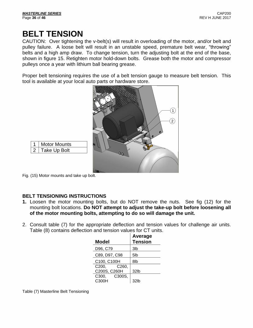
BELT TENSION CAUTION: Over tightening the v-belt(s) will result in overloading of the motor, and/or belt and pulley failure. A loose belt will result in an unstable speed, premature belt wear, “throwing” belts and a high amp draw. To change tension, turn the adjusting bolt at the end of the base, shown in figure 15. Retighten motor hold-down bolts. Grease both the motor and compressor pulleys once a year with lithium ball bearing grease. Proper belt tensioning requires the use of a belt tension gauge to measure belt tension. This tool is available at your local auto parts or hardware store.
1
2
Fig. (15) Motor mounts and take up bolt.
BELT TENSIONING INSTRUCTIONS 1. Loosen the motor mounting bolts, but do NOT remove the nuts. See fig (12) for the
mounting bolt locations. Do NOT attempt to adjust the take-up bolt before loosening all of the motor mounting bolts, attempting to do so will damage the unit.
2. Consult table (7) for the appropriate deflection and tension values for challenge air units. Table (8) contains deflection and tension values for CT units.
Model Average Tension
D96, C79 3lb
C89, D97, C98 5lb
C100, C100H 8lb
C200, C260, C200S, C260H 32lb
C300, C300S, C300H 32lb
Table (7) Masterline Belt Tensioning
1 Motor Mounts
2 Take Up Bolt
MASTERLINE SERIES CAP200 Page 37 of 46 REV H JUNE 2017
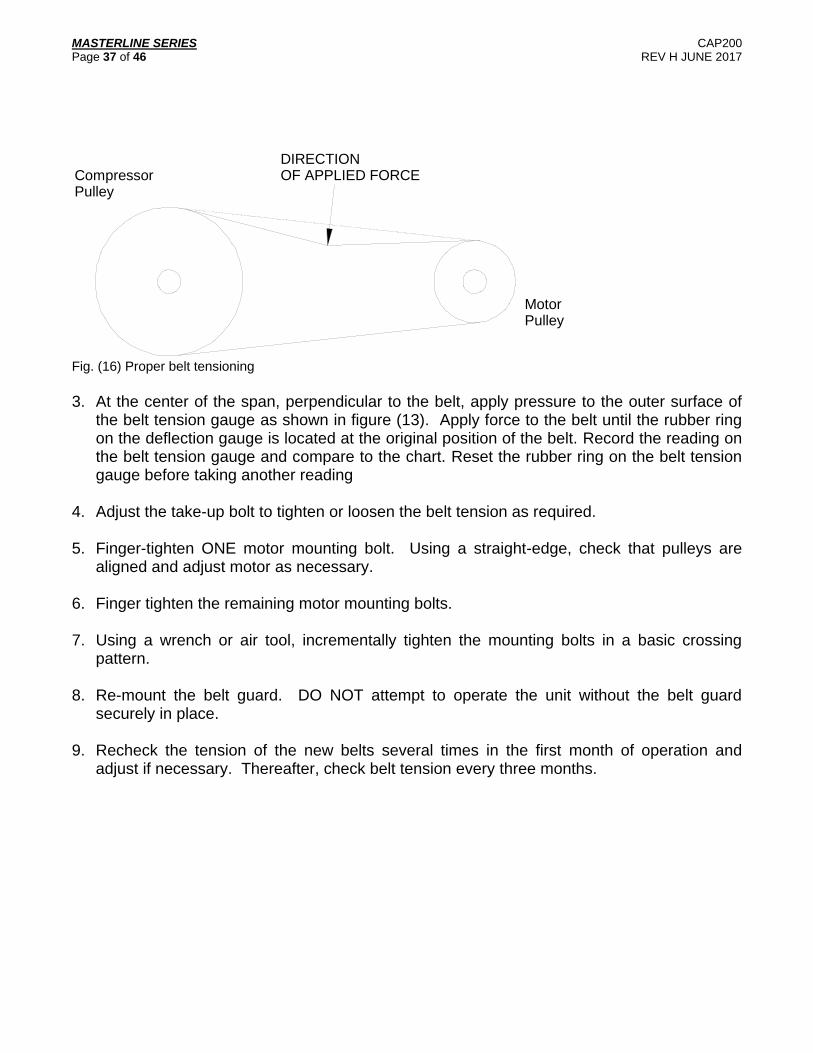
DIRECTIONOF APPLIED FORCE
MotorPulley
CompressorPulley
Fig. (16) Proper belt tensioning
3. At the center of the span, perpendicular to the belt, apply pressure to the outer surface of
the belt tension gauge as shown in figure (13). Apply force to the belt until the rubber ring on the deflection gauge is located at the original position of the belt. Record the reading on the belt tension gauge and compare to the chart. Reset the rubber ring on the belt tension gauge before taking another reading
4. Adjust the take-up bolt to tighten or loosen the belt tension as required.
5. Finger-tighten ONE motor mounting bolt. Using a straight-edge, check that pulleys are
aligned and adjust motor as necessary.
6. Finger tighten the remaining motor mounting bolts.
7. Using a wrench or air tool, incrementally tighten the mounting bolts in a basic crossing pattern.
8. Re-mount the belt guard. DO NOT attempt to operate the unit without the belt guard
securely in place.
9. Recheck the tension of the new belts several times in the first month of operation and adjust if necessary. Thereafter, check belt tension every three months.

MASTERLINE SERIES CAP200 Page 38 of 46 REV H JUNE 2017
INSTRUCTIONS UNLOADER PILOT VALVE
FUNCTION VV1002 Pilot Valve senses receiver (tank) pressure when the receiver pressure rises to the preset “unload” valve setting, the ball opens passing high pressure air to the compressor unloading device. When the receiver pressure drops to the preset “load” valve setting, the ball closes venting the compressor-unloading device to atmosphere. A manual override permits manual unloading of the compressor when placed in the up position. INSTALLATION Receiver (tank) pressure is connected to the 1/4” pipe thread inlet. The compressor-unloading device is connected to the 1/8” pipe outlet. .
Fig. (17) Pilot Valve
ADJUSTMENT PRESSURE ADJUSTMENT – The pilot valve is preset at assembly to a specified cutout and differential. A limited adjustment of the unload pressure may be made in the field. To adjust the unload pressure, unlock the locking nut (B), and turn the adjusting nut (A) clockwise for higher pressures and counterclockwise for lower pressures. CAUTION – As unload pressure is increased, the pressure differential between load and unload pressure will become larger. As unload pressure is decreased, the pressure differential will become smaller. A 30 PSI change in unload pressure will change the differential approximately 10 PSI. Therefore large changes in pressure adjustment must not be mad without adjusting the differential. A minimum differential of 10 PSI should be maintained to prevent system from loading and unloading too frequently. DIFFERENTIAL ADJUSTMENT – To increase the differential, unlock locknut (D), then turn cap nut (C) very slightly clockwise – not more than 1/4 of a turn at time. To decrease the differential, repeat above, but instead turn cap nut (C) counterclockwise. It may be necessary at this point to fine adjust the unload pressure as outlined in the Pressure Adjustment by turning the adjusting nut (A) in the proper direction. MAINTENANCE – If the pilot valve becomes erratic or fails to operate after being in use for some time, it should be disassembled, cleaned and reassembled. If the locknut (B) is loosened a minimum amount before removing adjusting nut (A), it will assist in adjusting the pressure setting on reassembly.

MASTERLINE SERIES CAP200 Page 39 of 46 REV H JUNE 2017
MAIN BEARING The main bearings are of the tapered roller type and must be shimmed or adjusted for end play as follows:
0.0005” to .002” for compressors D96, C79, C89 and D97.
0.0005” to .003” for compressors C98 and C100
0.002” to .004” for compressors C150, C200 and C260
0.004” to .006” for compressors C300
Maintenance Parts and Rebuild Kits To order replacement parts for routine maintenance, please contact your local distributor. MASTERLINE REBUILD KITS
D96 C79 D97 C89 C98
Oil (12 quart case) VO411-3 VO411-3 VO411-3 VO411-3 VO411-3
Oil and Air Filter VGC802 VGC803 VGC800 VGC800 VGC801
Gasket Kit VGC807 VGC808 VGC804 VGC805 VGC806
Upper End Kit VGC812 VGC813 VGC809 VGC810 VGC811
Piston Ring Kit VGC822 VGC823 VGC819 VGC820 VGC821
Lower End Kit VGC817 VGC818 VGC814 VGC815 VGC816
Full Rebuild Kit VGC827 VGC828 VGC824 VGC825 VGC826
C100 C100S C150H C200 C200S
Oil (5 gallon pail) VO421-1 VO421-1 VO421-1 VO425 VO421-1
Oil and Air Filter CCC1850 CCC1845 CCC1888 CCC1847 CCC1848
Gasket Kit CMA741 CMA742 CMA742 CMA817 CMA889
Valve/Gasket Kit CO1874 CO1874 CO1874 C1875 C1875
Lower End Kit CO1927 CO1926 CO1929 CO1931 CO1930
Full Rebuild Kit CDB1456 CDB1457 CDB1458 CDB1459 CDB1460
C260H C300 C300S C300H
Oil (5 gallon pail) VO425 VO425 VO421-1 VO425
Oil and Air Filter CCC1885 CCC1846 CCC1849 CCC1884
Gasket Kit CMA817 CM965 CM965 CM965
Valve/Gasket Kit C1875 C1876 C1876 C1876
Lower End Kit CO1932 CO1934 CO1933 CO1936
Full Rebuild Kit CDB1462 CDB1463 CDB1464 CDB1466
Table (9) Routine Maintenance Parts and Rebuild Kits for Masterline compressors

MASTERLINE SERIES CAP200 Page 40 of 46 REV H JUNE 2017
Troubleshooting If your problem is not caused after working through the checklist below, please contact your local distributor.
Problem Cause Remedy
1 Unit won’t start
Power not on
Fuse blown
Low voltage supplied
Worn pressure switch contacts
Starter overload tripped
Broken / loose electrical
connections
Check breaker and / or disconnect
Replace the fuse or disconnect
Contact distributor
Replace
Reset starter overload
Check electrical connections
2 Flywheel / motor rotating clockwise
Incorrect lead connection Reverse the leads
3 Flywheel /motor rotating slowly
Excessively dirty oil
Heavy lubrication oil
Oil thick due to low temperature
Belt slipping
Incorrect voltage
Change the oil
Use correct oil
Increase ambient temperature above
40°F
See 6
Contact distributor
4 Excessive Vibrations
Vibration pads not installed
Unit not leveled
Unit not securely fastened
Install vibration pads
Level unit with metal shims
Check for loose bolts on foundation,
compressor, and motor
5 Compressor overheats
Ambient air temperature too high
Degraded oil
Incorrect oil
Clogged Air Intake
Interior or exterior fouling of the
intercooler
Ensure adequate ventilation
Change oil
Use correct oil
Replace filter and clean intake
Clean intercooler
6 Belt slipping
Working pressure too high
Low belt tension
Worn belt
Incorrect belt
Worn or misaligned pulley
Lower working pressure
Adjust belt tension
Replace
Install correct belt
Replace or align pulley

MASTERLINE SERIES CAP200 Page 41 of 46 REV H JUNE 2017
Problem Cause Remedy
7 Low discharge pressure
Manual drain not fully closed
(standard model)
Automatic drain not fully closed (if
applicable)
Clogged air filter / intake
Leaks in air distribution system
Clogged air distribution system
Worn out pressure switch
Belt slipping
Worn piston rings
Worn head gasket
Worn valves
Close the drain cock
Clean or replace automatic drain
Replace the filter
Check fittings, bushings and
connections for leaks
Clean air distribution system
Replace pressure switch
See 6
Replace with ring kit
Replace with gasket kit
Replace with valve kit
8 Excessive belt wear
Belt too tight or too loose
Incorrect belt
Exposure to abrasive dust
Working pressure too high
Worn or misaligned pulley
Adjust belt tension
Use correct belt
Eliminate dust or relocate unit
Lower working pressure
Replace or realign pulley
9 Lubricant appears milky
Water in the crankcase
Incorrect oil
Water contaminated oil
Water leaking back through
discharge / intake valve
Compressor not running long enough to
prevent condensation
Use correct oil
Replace oil
Re-pipe with drip legs and pitch piping
away from the compressor
10 Excessive oil in compressed air
Oil level too high
Incorrect oil
Piston ring not fully seated
Worn piston ring
Bleed excess oil
Use correct oil
Allow 100 hours to break in rings
Replace with ring kit
11 Motor overloads Working pressure too high
Incorrect voltage
Lower working pressure
Contact distributor
12 Low Oil Pressure (Large Industrials)
Compressor running slow
Low oil level
Dirty Oil Filter / strainer
Worn shaft bearings
See 3
Change oil
Clean and / or replace
Replace

MASTERLINE SERIES CAP200 Page 42 of 46 REV H JUNE 2017
Maintenance Check off List NOTE: Please keep a record of changes and have this list available when calling technical service. OIL CHANGED
Initials Date Changed
Oil Low? (y/n)
Initials Date Changed
Oil Low? (y/n)
BELT TENSIONING
Initials Date Checked
Measurement Initials Date Checked
Measurement

MASTERLINE SERIES CAP200 Page 43 of 46 REV H JUNE 2017
Maintenance Check off List NOTE: Please keep a record of changes and have this list available when calling technical service. Valve Inspected
Initials Date Checked
Initials Date Checked
Air Leak Checks
Initials Date Checked
Comments Initials Date Checked
Comments

MASTERLINE SERIES CAP200 Page 44 of 46 REV H JUNE 2017
Maintenance Check off List NOTE: Please keep a record of changes and have this list available when calling technical service. Air Filter
Initials Date Replaced
Initials Date Replaced
Intercooler / Aftercooler Cleaning
Initials Date Checked
Initials Date Checked

MASTERLINE SERIES CAP200 Page 45 of 46 REV H JUNE 2017
NOTES

MASTERLINE SERIES CAP200 Page 46 of 46 REV H JUNE 2017
NOTES

Curtis-Toledo, Inc.
1905 Kienlen Avenue | St. Louis, Missouri 63133
314-383-1300 or 800-925-5431
www.fscurtis.com | [email protected]