Embed Size (px)
Citation preview
PLC System Presentation.doc 1/2/01
PROGRAMMABLE LOGIC CONTROLLERS AT
JEFFERSON LAB
Henry Robertson Safety Systems Group TJNAF/Jefferson Lab

PLC System Presentation.doc 1/2/01
USES OF PROGRAMMABLE LOGIC CONTROLLERS AT JEFFERSON LAB
• Equipment Status
• Process Control
• Chemical Processing
• Equipment Interlocks
• Machine Protection
• Smoke Detection
• Gas Monitoring
• Envelope Monitoring
• Personnel Safety

PLC System Presentation.doc 1/2/01
USES OF PROGRAMMABLE LOGIC CONTROLLERS AT JEFFERSON LAB Chemical Processing Processing of Niobium Super conducting cavities uses a buffer chemical polish BCP Acids: Hydroflouric Phosphoric Nitric Chemical processing cabinet that is normally used for semiconductor wafer processing Built to the semi-conductor industry standard SEMI S93.02

PLC System Presentation.doc 1/2/01
USES OF PROGRAMMABLE LOGIC CONTROLLERS AT JEFFERSON LAB Gas Monitoring Experimental Hall B PLCs used for alarm functions System Part of Evaluated by Factory Mutual Corp. Oxygen Monitoring (for ODH) in CEBAF tunnels and halls Processor based Networked transmitters / sensors

PLC System Presentation.doc 1/2/01
USES OF PROGRAMMABLE LOGIC CONTROLLERS AT JEFFERSON LAB Machine Protection Free Electron Laser Machine Protection System PLCs used for system set up and device monitoring Automatically detects FEL configuration and limits beam current to appropriate level
PLC System Presentation.doc 1/2/01
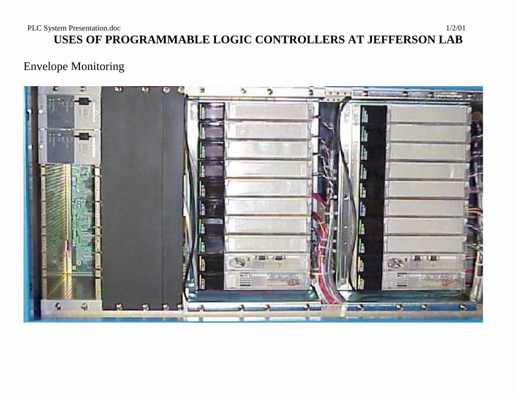
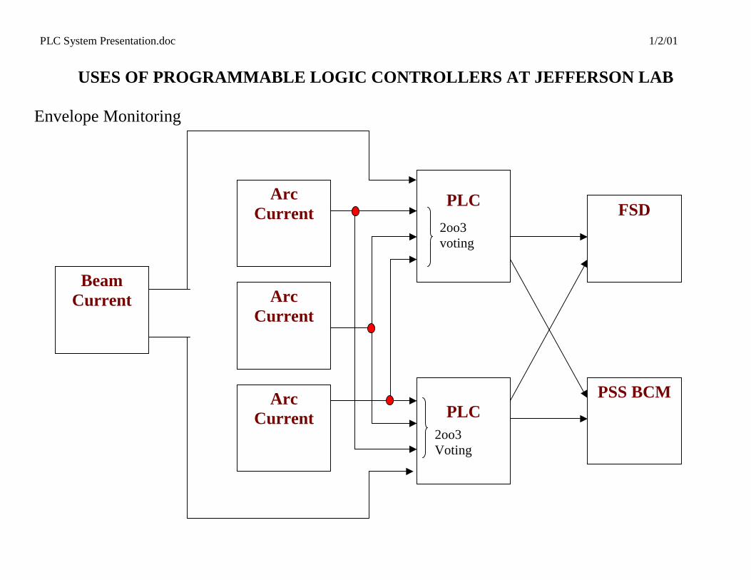
USES OF PROGRAMMABLE LOGIC CONTROLLERS AT JEFFERSON LAB Envelope Monitoring Beam Envelope Limit System (BELS) Used to ensure that nuclear physics accelerator remains within operations and safety envelope Allows beam operation close to envelope limits Measures beam power Redundant PLCs using voting arrangement on inputs
PLC System Presentation.doc 1/2/01
USES OF PROGRAMMABLE LOGIC CONTROLLERS AT JEFFERSON LAB Envelope Monitoring
PLC System Presentation.doc 1/2/01
USES OF PROGRAMMABLE LOGIC CONTROLLERS AT JEFFERSON LAB
Envelope Monitoring
Arc Current
PLC FSD
Beam Current
PLC
PSS BCM
Arc Current
Arc Current
2oo3 voting
2oo3 Voting
PLC System Presentation.doc 1/2/01
USING PLCS IN THE PERSONNEL SAFETY SYSTEM Why Programmable Controllers?
• Complexity – Much less complex than large relay based system
• Modularity – Very flexible due to network architecture
• Documentation – Virtually self-documenting
• Resource limitations – Very space efficient and less manpower required to install
• Cost and schedule – Up front material costs are similar, but savings on installation, maintenance, and troubleshooting increase rapidly as system size increases
• Reliability – Industry and lab experience demonstrate PLCs comparable to relay system
• Familiarity – Huge knowledge base in industry
• Training – Short learning curve for hardware and programming
• Troubleshooting – Ability to monitor every sensor speeds debug and repair

PLC System Presentation.doc 1/2/01
USING PLCS IN THE PERSONNEL SAFETY SYSTEM
• Programmable Logic Controllers (PLC) used to emulate relay logic interlocks and provide device status
• Special computers/software used for programming and status
• Stringent programming procedure used
• Rigorous testing procedures followed
• Hardware and software changes tightly controlled
• Proven high reliability and availability

PLC System Presentation.doc 1/2/01
PROGRAMMABLE LOGIC CONTROLLER SYSTEM
• 2 independent PLC systems (A and B)
• Each system consists of approximately 1000+ I/O points
• System segmented into 6 physical areas for modularity
• High speed network used for peer-to-peer communication
• Fiber optic modems provide long distance networking and EMI isolation
• Discrete monitoring of every sensor device
• Discrete management of every control device

PLC System Presentation.doc 1/2/01
PROGRAMMABLE LOGIC CONTROLLER SYSTEM
• Human Machine Interface (HMI) software allows standardized status screens
• Secure stand-alone computer and software for programming logic
• Throughput / response time < .5 seconds
• High-density modules allow efficient use of rack space
• “Soft” wiring requires only one person
• Built-in diagnostics simplify trouble-shooting

PLC System Presentation.doc 1/2/01
TYPICAL PLC SYSTEM NETWORK (1 OF 2)
Fiber Optic Modem
Fiber Optic Modem
Hardwired Feedback
Master Drop w/ Local I/O
Master Drop w/ Local I/O Remote I/O Drop
Peer-to-Peer Network Program Computer
Display Computer
Fiber Optic Modem
Fiber Optic Modem
Master Drop w/ Local I/O
Master Dropw/ Local I/O
Master Drop w/ Local I/O
Master Drop w/ Local I/O
Peer-to-P r Network
Master Drop w/ Local I/O
Remote I/O Drop
ee
PLC System Presentation.doc 1/2/01
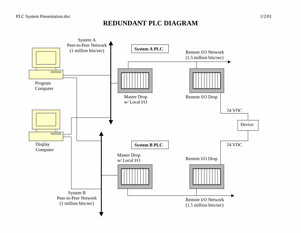
REDUNDANT PLC DIAGRAM
Master Drop w/ Local I/O
Remote I/O Drop
Master Drop w/ Local I/O
System A PLC
Syst B PLC
System B Peer-to-Peer Network
(1 million bits/sec)
Pro m Com ter
Display Computer
System A Peer-to-Peer Network
(1 million bits/sec) Remote I/O Network (1.5 million bits/sec)
Device
24 VDC
24 VDC
emRe Drop
Re(1.
mote I/O
grapu
mote I/O Network 5 million bits/sec)

PLC System Presentation.doc 1/2/01
EXAMPLE OF REDUNDANT SAFETY INTERLOCK
Sensor output must be +24 V to indicate safe. PLC output must be +24 V to energize the controlled device.
Isolation is provided by relays, opto-couplers, or both.
PLC B
Input Module
OutputModule
Main Processor
Module
PLC A
Input Module
OutputModule
Main Processor
Module
Control CircuitControlled Device
Sensor
Sensor
Isolation Isolation
Isolation Isolation
Permissive
Permissive
Status
Status

PLC System Presentation.doc 1/2/01
MASTER PLC DROP WITH LOCAL I/O

PLC System Presentation.doc 1/2/01
SEGMENTATION
• Site is segmented into 6 physical areas Injector/North Linac, South Linac, Beam Switchyard, Hall A, Hall B, Hall C
• PLC Masters are located in each physical area (some areas include Remote I/O drops)
• Allows separate maintenance and auditing of each segment
• Allows operation and test of the accelerator in logical pieces
• Each segment can operate independently up to the point where operation of a device within one area may present a hazard in another area
• At that point the areas must agree that it is safe to operate the hazardous device
• Inter-segment communication handled with hardwired handshake

PLC System Presentation.doc 1/2/01
In je c to r/N o rth L in a c S e g m e n t
S o u th L in a c S e g m e n t
H a ll A
S e g m e n t
H a ll B
S e g m e n t
H a ll C
S e g m e n t
B e a m S w itch ya rd S e g m e n t
W e st
B S Y
S h ie ld W a lls
E a s t
Hall A
Hall B
Hall C
BSY
North Linac
South Linac
Injector Gun On?
PSS Segment Intercommunication
PLC System Presentation.doc 1/2/01
HMI / SYSTEM MONITORING Four computers are used in the monitoring of the PSS
• Display computer - operates as the safety system operator’s display
• Development Computer - operates as the PSS technician’s remote display
• Program Computer - programming, diagnostic, and performance monitoring of the PLC logic
• X-terminal - passes PSS status to the JLAB instrumentation and control system, EPICS

PLC System Presentation.doc 1/2/01
DISPLAY / DEVELOPMENT COMPUTERS
• Local and remote status screens
• Trouble-shooting screens
• Flexible interface for easily customized screens
• Includes security, alarming, and event logging functions
• Uses network to monitor status of each area
• No critical information, e.g. interlock logic, is transferred over the network
• Configured as a read-only device
PLC System Presentation.doc 1/2/01
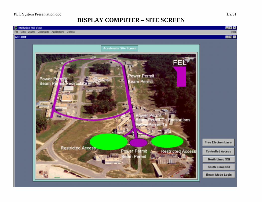
DISPLAY COMPUTER – SITE SCREEN

PLC System Presentation.doc 1/2/01
STATUS SCREENS FOR NORTH LINAC SEGMENT

PLC System Presentation.doc 1/2/01
STATUS SCREENS FOR NORTH LINAC SEGMENT

PLC System Presentation.doc 1/2/01
STATUS ICONS Inputs are grouped by function The PSS system A and System B inputs are shown separately as a circular icon. A GREEN icon means the device is in the OK or safe condition. A RED icon means the device is in the fault or unsafe condition.
Radiation Monitors A B RM 201 RM 202
PLC A or B
Status Icon
Device Number
PLC System Presentation.doc 1/2/01
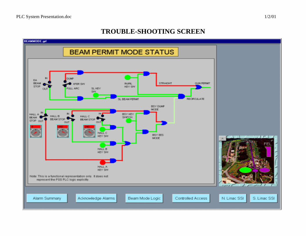
TROUBLE-SHOOTING SCREEN
PLC System Presentation.doc 1/2/01
PLC PROGRAMMING
• PLCs are programmed by two independent programmers
• Information on implementation and algorithms are not shared
• Each person writes the program to conform to a general functional specification of how the
logic system should behave
• Each PSS segment has a general logic specification
• The specification gives a functional and logical description of the PLC logic for the area
• The specification is careful to avoid detailed algorithms or suggested implementations
• This allows the greatest degree of freedom in the actual implementation of the logic
• The logic spec defines two types of logic
1. state logic, e.g., Restricted Access, Sweep, Controlled Access, etc.
2. device logic - defines the requirements for the PSS interface with a given device

PLC System Presentation.doc 1/2/01
EXAMPLE OF THE SPEC FOR STATE LOGIC
Beam Permit = [ Doors and Gates & / Crash & Exchange Key IN & Sweep Complete & Radiation Monitor OK & High Voltage Ready & / Laser Bypass &
External Systems Ready & Chain Intact & ( Beam Permit Key Switch Timer OR Beam Permit Mode ) ]
PLC System Presentation.doc 1/2/01
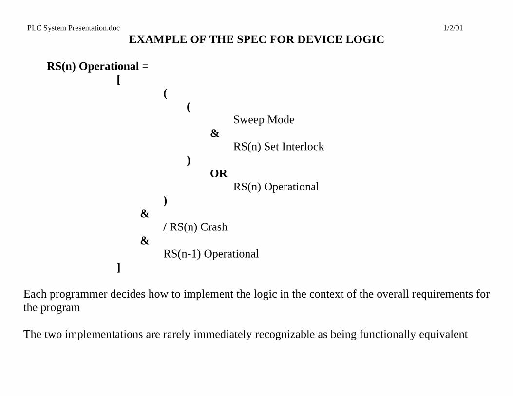
EXAMPLE OF THE SPEC FOR DEVICE LOGIC
RS(n) Operational = [ ( ( Sweep Mode & RS(n) Set Interlock ) OR RS(n) Operational ) & / RS(n) Crash & RS(n-1) Operational ] Each programmer decides how to implement the logic in the context of the overall requirements for the program The two implementations are rarely immediately recognizable as being functionally equivalent

PLC System Presentation.doc 1/2/01
PROGRAMMING APPLICATION WITH TYPICAL LADDER LOGIC DIAGRAM

PLC System Presentation.doc 1/2/01
DOCUMENTATION
• Virtually self-documenting
• Ladder Logic diagrams with common name descriptors
• “Traffic Cop” system configuration listings
• Detailed listings of all I/O used including descriptions
• Processor and network configuration details

PLC System Presentation.doc 1/2/01
SAFETY SYSTEM CERTIFICATION
• Adheres to Jefferson Lab Certification Procedure
• Full Certification of the complete PSS is done semi-annually
• An Operation's Crew Chief serves as the Test Director
• Full Certification required for:
If any part of the PLC interlock logic has been changed If the PLC CPU has been removed from the crate
• Partial Certification required for: Required for any device or subsystem which has been modified Modification includes temporary disconnection and/or replacement. Must include all components affected by or connected to the device/system replaced
PLC System Presentation.doc 1/2/01
SAFETY SYSTEMS GROUP CERTIFICATION PROCEDURES
• Must follow Static and Functional test procedures exactly
• Static test of all PSS inputs and outputs
• Functional test of the operation of the PSS logic
• Tests the separate response of systems A and B to ensure that each responds independently
PLC System Presentation.doc 1/2/01
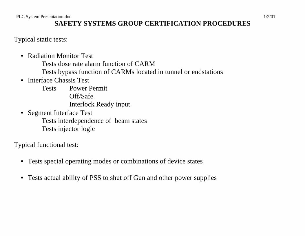
SAFETY SYSTEMS GROUP CERTIFICATION PROCEDURES Typical static tests:
• Radiation Monitor Test Tests dose rate alarm function of CARM Tests bypass function of CARMs located in tunnel or endstations
• Interface Chassis Test Tests Power Permit Off/Safe Interlock Ready input
• Segment Interface Test Tests interdependence of beam states Tests injector logic Typical functional test:
• Tests special operating modes or combinations of device states
• Tests actual ability of PSS to shut off Gun and other power supplies

PLC System Presentation.doc 1/2/01
CONFIGURATION CONTROL Jefferson Lab Configuration Control Policy
• Sets baseline configuration
• Explains change control procedure
• Describes system classification levels
• Sets up configuration accounting
• Defines special rules for hardware and software repairs
• Classifies systems and devices by level of control
• Includes required forms and process instructions

PLC System Presentation.doc 1/2/01
CONFIGURATION CONTROL Installation considerations:
• Isolation
• Protection
• Labeling Security measures:
• Password access to all computers
• Secured Memory Protect key

PLC System Presentation.doc 1/2/01
RELIABILITY AND AVAILABILITY
Reliability Years of operation 10 1/2 Faults causing hazard to personnel (fail unsafe) 0 Faults caused by software 0 Hardware failures:
• Power Supply - 2
• CPU - 0
• Communication - 3
• Input - 1
• Output – 4 Most hardware faults have been related to lightning or improper installation procedures
PLC System Presentation.doc 1/2/01
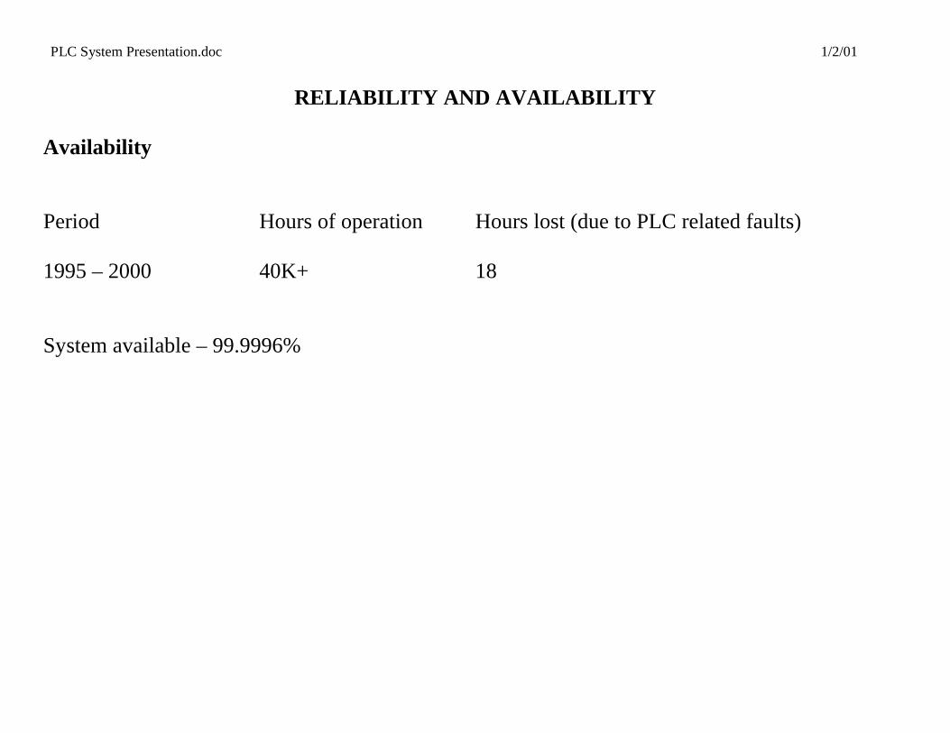
RELIABILITY AND AVAILABILITY
Availability Period Hours of operation Hours lost (due to PLC related faults) 1995 – 2000 40K+ 18 System available – 99.9996%