Embed Size (px)
Citation preview
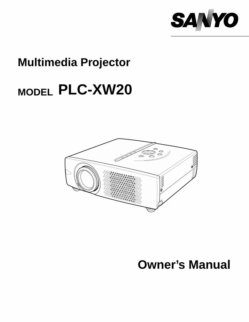
Owner’s Manual
PLC-XW20
Multimedia Projector
MODEL
2
CAUTION : TO REDUCE THE RISK OF ELECTRIC SHOCK, DO NOT REMOVE COVER (OR BACK). NO USER-SERVICEABLE PARTS INSIDE EXCEPT LAMP REPLACEMENT. REFER SERVICING TO QUALIFIEDSERVICE PERSONNEL.
THIS SYMBOL INDICATES THAT DANGEROUSVOLTAGE CONSTITUTING A RISK OF ELECTRICSHOCK IS PRESENT WITHIN THIS UNIT.
THIS SYMBOL INDICATES THAT THERE ARE IMPORTANTOPERATING AND MAINTENANCE INSTRUCTIONS IN THEOWNER'S MANUAL WITH THIS UNIT.
CAUTIONRISK OF ELECTRIC SHOCK
DO NOT OPEN
Before operating this projector, read this manual thoroughly and operate the projector properly. This projector provides many convenient features and functions. Operating the projector properly enables you tomanage those features and maintains it in better condition for a considerable time.Improper operation may result in not only shortening the product-life, but also malfunctions, fire hazard, or otheraccidents.If your projector seems to operate improperly, read this manual again, check operations and cable connections and trythe solutions in the “Trouble-shooting” section of the end of this booklet. If the problem still persists, contact the salesdealer where you purchased the projector or the service center.
TO THE OWNER
SAFETY PRECAUTIONSWARNING : TO REDUCE THE RISK OF FIRE OR ELECTRIC SHOCK, DO NOT EXPOSE THIS APPLIANCE TO
RAIN OR MOISTURE.
● This projector produces intense light from the projection lens. Do not stare directly into the lens as possible.Eye damage could result. Be especially careful that children do not stare directly into the beam.
● This projector should be set in the way indicated. If not, it may result in a fire hazard.
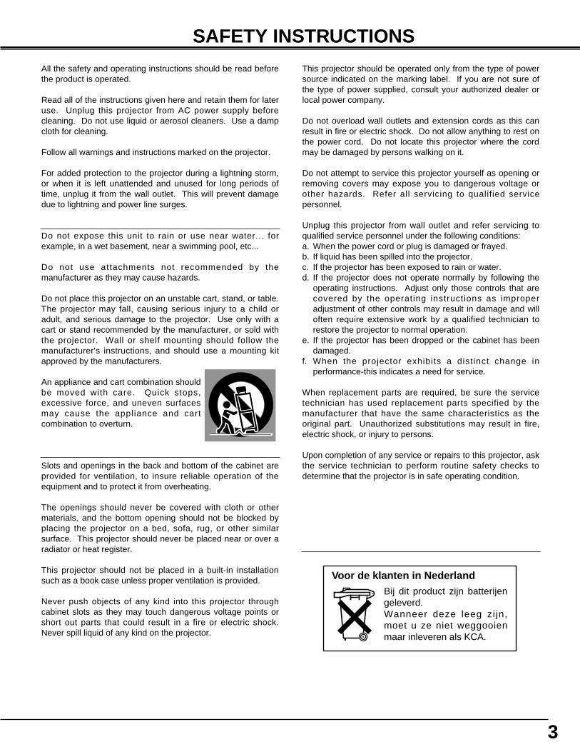
● Take appropriate space on the top, sides and rear of the projectorcabinet for allowing air circulation and cooling the projector.Minimum distance should be taken. If the projector is to be builtinto a compartment or similarly enclosed, the minimum distancesmust be maintained. Do not cover the ventilation slot on theprojector. Heat build-up can reduce the service life of yourprojector, and can also be dangerous.
● Do not put any flammable object or spray can near the projector, hot air is exhausted from the ventilationholes.
● If the projector is not to be used for an extended time, unplug the projector from the power outlet.
READ AND KEEP THIS OWNER'S MANUAL FOR LATER USE.
20cm
50cm 50cm 50cm
SIDE and TOP REAR
3
SAFETY INSTRUCTIONS
All the safety and operating instructions should be read beforethe product is operated.
Read all of the instructions given here and retain them for lateruse. Unplug this projector from AC power supply beforecleaning. Do not use liquid or aerosol cleaners. Use a dampcloth for cleaning.
Follow all warnings and instructions marked on the projector.
For added protection to the projector during a lightning storm,or when it is left unattended and unused for long periods oftime, unplug it from the wall outlet. This will prevent damagedue to lightning and power line surges.
Do not expose this unit to rain or use near water... forexample, in a wet basement, near a swimming pool, etc...
Do not use attachments not recommended by themanufacturer as they may cause hazards.
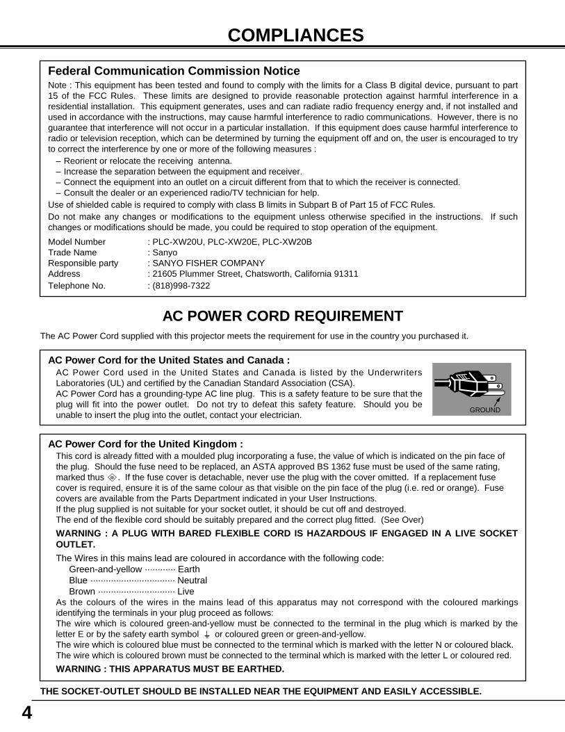
Do not place this projector on an unstable cart, stand, or table.The projector may fall, causing serious injury to a child oradult, and serious damage to the projector. Use only with acart or stand recommended by the manufacturer, or sold withthe projector. Wall or shelf mounting should follow themanufacturer's instructions, and should use a mounting kitapproved by the manufacturers.
An appliance and cart combination shouldbe moved with care. Quick stops,excessive force, and uneven surfacesmay cause the appliance and cartcombination to overturn.
Slots and openings in the back and bottom of the cabinet areprovided for ventilation, to insure reliable operation of theequipment and to protect it from overheating.
The openings should never be covered with cloth or othermaterials, and the bottom opening should not be blocked byplacing the projector on a bed, sofa, rug, or other similarsurface. This projector should never be placed near or over aradiator or heat register.
This projector should not be placed in a built-in installationsuch as a book case unless proper ventilation is provided.
Never push objects of any kind into this projector throughcabinet slots as they may touch dangerous voltage points orshort out parts that could result in a fire or electric shock.Never spill liquid of any kind on the projector.
This projector should be operated only from the type of powersource indicated on the marking label. If you are not sure ofthe type of power supplied, consult your authorized dealer orlocal power company.
Do not overload wall outlets and extension cords as this canresult in fire or electric shock. Do not allow anything to rest onthe power cord. Do not locate this projector where the cordmay be damaged by persons walking on it.
Do not attempt to service this projector yourself as opening orremoving covers may expose you to dangerous voltage orother hazards. Refer all servicing to qualified servicepersonnel.
Unplug this projector from wall outlet and refer servicing toqualified service personnel under the following conditions:a. When the power cord or plug is damaged or frayed.b. If liquid has been spilled into the projector.c. If the projector has been exposed to rain or water.d. If the projector does not operate normally by following the
operating instructions. Adjust only those controls that arecovered by the operating instructions as improperadjustment of other controls may result in damage and willoften require extensive work by a qualified technician torestore the projector to normal operation.
e. If the projector has been dropped or the cabinet has beendamaged.
f. When the projector exhibits a distinct change inperformance-this indicates a need for service.
When replacement parts are required, be sure the servicetechnician has used replacement parts specified by themanufacturer that have the same characteristics as theoriginal part. Unauthorized substitutions may result in fire,electric shock, or injury to persons.
Upon completion of any service or repairs to this projector, askthe service technician to perform routine safety checks todetermine that the projector is in safe operating condition.
Voor de klanten in NederlandBij dit product zijn batterijengeleverd. Wanneer deze leeg zijn,moet u ze niet weggooienmaar inleveren als KCA.
4
COMPLIANCES
AC Power Cord for the United Kingdom :This cord is already fitted with a moulded plug incorporating a fuse, the value of which is indicated on the pin face ofthe plug. Should the fuse need to be replaced, an ASTA approved BS 1362 fuse must be used of the same rating,marked thus . If the fuse cover is detachable, never use the plug with the cover omitted. If a replacement fusecover is required, ensure it is of the same colour as that visible on the pin face of the plug (i.e. red or orange). Fusecovers are available from the Parts Department indicated in your User Instructions.If the plug supplied is not suitable for your socket outlet, it should be cut off and destroyed.The end of the flexible cord should be suitably prepared and the correct plug fitted. (See Over)
WARNING : A PLUG WITH BARED FLEXIBLE CORD IS HAZARDOUS IF ENGAGED IN A LIVE SOCKETOUTLET.The Wires in this mains lead are coloured in accordance with the following code:
Green-and-yellow ············ EarthBlue ································· NeutralBrown ······························ Live
As the colours of the wires in the mains lead of this apparatus may not correspond with the coloured markingsidentifying the terminals in your plug proceed as follows:The wire which is coloured green-and-yellow must be connected to the terminal in the plug which is marked by theletter E or by the safety earth symbol or coloured green or green-and-yellow.The wire which is coloured blue must be connected to the terminal which is marked with the letter N or coloured black.The wire which is coloured brown must be connected to the terminal which is marked with the letter L or coloured red.
WARNING : THIS APPARATUS MUST BE EARTHED.
ASA
The AC Power Cord supplied with this projector meets the requirement for use in the country you purchased it.
AC Power Cord for the United States and Canada :AC Power Cord used in the United States and Canada is listed by the UnderwritersLaboratories (UL) and certified by the Canadian Standard Association (CSA).AC Power Cord has a grounding-type AC line plug. This is a safety feature to be sure that theplug will fit into the power outlet. Do not try to defeat this safety feature. Should you beunable to insert the plug into the outlet, contact your electrician.
GROUND
THE SOCKET-OUTLET SHOULD BE INSTALLED NEAR THE EQUIPMENT AND EASILY ACCESSIBLE.
AC POWER CORD REQUIREMENT
Federal Communication Commission NoticeNote : This equipment has been tested and found to comply with the limits for a Class B digital device, pursuant to part15 of the FCC Rules. These limits are designed to provide reasonable protection against harmful interference in aresidential installation. This equipment generates, uses and can radiate radio frequency energy and, if not installed andused in accordance with the instructions, may cause harmful interference to radio communications. However, there is noguarantee that interference will not occur in a particular installation. If this equipment does cause harmful interference toradio or television reception, which can be determined by turning the equipment off and on, the user is encouraged to tryto correct the interference by one or more of the following measures :
– Reorient or relocate the receiving antenna.– Increase the separation between the equipment and receiver.– Connect the equipment into an outlet on a circuit different from that to which the receiver is connected.– Consult the dealer or an experienced radio/TV technician for help.
Use of shielded cable is required to comply with class B limits in Subpart B of Part 15 of FCC Rules.Do not make any changes or modifications to the equipment unless otherwise specified in the instructions. If suchchanges or modifications should be made, you could be required to stop operation of the equipment.
Model Number : PLC-XW20U, PLC-XW20E, PLC-XW20BTrade Name : SanyoResponsible party : SANYO FISHER COMPANYAddress : 21605 Plummer Street, Chatsworth, California 91311Telephone No. : (818)998-7322
5
TABLE OF CONTENTS
FEATURES AND DESIGN 6
BEFORE OPERATION 14
COMPUTER INPUT 22
VIDEO INPUT 30
SETTING 35
APPENDIX 37
PREPARATION 7
NAME OF EACH PART OF PROJECTOR 7SETTING-UP PROJECTOR 8
CONNECTING AC POWER CORD 8POSITIONING PROJECTOR 9ADJUSTABLE FEET 9MOVING PROJECTOR 10
CONNECTING PROJECTOR 11
TERMINALS OF PROJECTOR 11CONNECTING TO COMPUTER 12CONNECTING TO VIDEO EQUIPMENT 13
OPERATION OF REMOTE CONTROL 14OPERATING RANGE 15REMOTE CONTROL BATTERY INSTALLATION 15
TOP CONTROLS AND INDICATORS 16OPERATING ON-SCREEN MENU 17
HOW TO OPERATE ON-SCREEN MENU 17FLOW OF ON-SCREEN MENU OPERATION 17MENU BAR 18
SELECTING INPUT SOURCE 22SELECTING COMPUTER SYSTEM 22
COMPATIBLE COMPUTER SPECIFICATIONS 23
PC ADJUSTMENT 24AUTO PC ADJUSTMENT 24MANUAL PC ADJUSTMENT 25
PICTURE IMAGE ADJUSTMENT 27IMAGE LEVEL SELECT 27IMAGE LEVEL ADJUSTMENT 28
PICTURE SCREEN ADJUSTMENT 29
SELECTING INPUT SOURCE 30SELECTING VIDEO SYSTEM 31PICTURE IMAGE ADJUSTMENT 32
IMAGE LEVEL SELECT 32IMAGE LEVEL ADJUSTMENT 33
PICTURE SCREEN ADJUSTMENT 34
SETTING MENU 35
MAINTENANCE 37WARNING TEMP. INDICATOR 37AIR FILTER CARE AND CLEANING 37CLEANING PROJECTION LENS 37LAMP REPLACEMENT 38LAMP REPLACE COUNTER 38
TROUBLESHOOTING 39TECHNICAL SPECIFICATIONS 41
BASIC OPERATION 19
TURNING ON / OFF PROJECTOR 19ADJUSTING SCREEN 20
ZOOM ADJUSTMENT 20FOCUS ADJUSTMENT 20KEYSTONE ADJUSTMENT 20PICTURE FREEZE FUNCTION 20NO SHOW FUNCTION 21P-TIMER FUNCTION 21
SOUND ADJUSTMENT 21
TRADEMARKS● Apple, Macintosh, and PowerBook are trademarks or registered trademarks of Apple Computer,Inc.● IBM and PS/2 are trademarks or registered trademarks of International Business Machines, Inc.● Windows and PowerPoint are registered trademarks of Microsoft Corporation.● Each name of corporations or products in the owner's manual is a trademark or a registered trademark of its
respective corporation.
6
FEATURES AND DESIGN
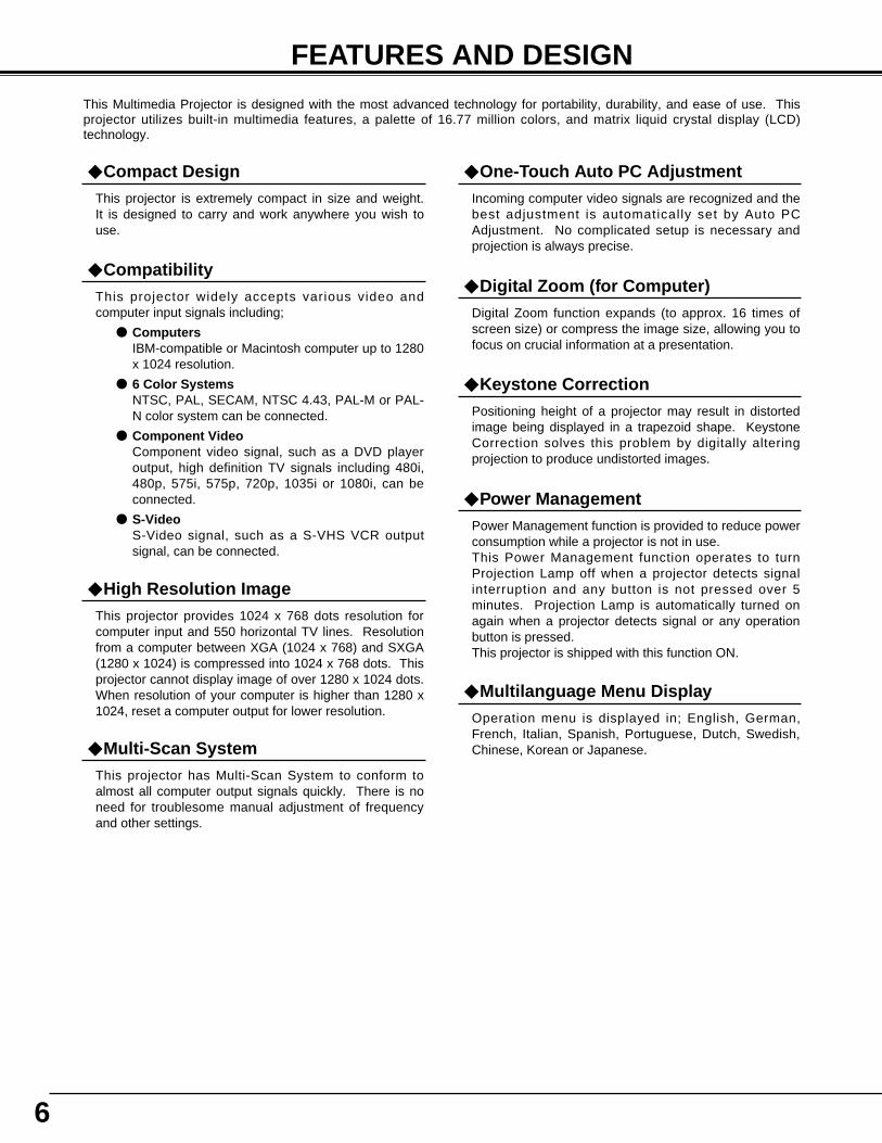
This Multimedia Projector is designed with the most advanced technology for portability, durability, and ease of use. Thisprojector utilizes built-in multimedia features, a palette of 16.77 million colors, and matrix liquid crystal display (LCD)technology.
◆ CompatibilityThis projector widely accepts various video andcomputer input signals including;
● ComputersIBM-compatible or Macintosh computer up to 1280x 1024 resolution.
● 6 Color SystemsNTSC, PAL, SECAM, NTSC 4.43, PAL-M or PAL-N color system can be connected.
● Component VideoComponent video signal, such as a DVD playeroutput, high definition TV signals including 480i,480p, 575i, 575p, 720p, 1035i or 1080i, can beconnected.
● S-VideoS-Video signal, such as a S-VHS VCR outputsignal, can be connected.
◆ High Resolution ImageThis projector provides 1024 x 768 dots resolution forcomputer input and 550 horizontal TV lines. Resolutionfrom a computer between XGA (1024 x 768) and SXGA(1280 x 1024) is compressed into 1024 x 768 dots. Thisprojector cannot display image of over 1280 x 1024 dots.When resolution of your computer is higher than 1280 x1024, reset a computer output for lower resolution.
◆ Multi-Scan SystemThis projector has Multi-Scan System to conform toalmost all computer output signals quickly. There is noneed for troublesome manual adjustment of frequencyand other settings.
◆ Keystone CorrectionPositioning height of a projector may result in distortedimage being displayed in a trapezoid shape. KeystoneCorrection solves this problem by digitally alteringprojection to produce undistorted images.
◆ Multilanguage Menu DisplayOperation menu is displayed in; English, German,French, Italian, Spanish, Portuguese, Dutch, Swedish,Chinese, Korean or Japanese.
◆ One-Touch Auto PC AdjustmentIncoming computer video signals are recognized and thebest adjustment is automatically set by Auto PCAdjustment. No complicated setup is necessary andprojection is always precise.
◆ Digital Zoom (for Computer)Digital Zoom function expands (to approx. 16 times ofscreen size) or compress the image size, allowing you tofocus on crucial information at a presentation.
◆ Compact DesignThis projector is extremely compact in size and weight.It is designed to carry and work anywhere you wish touse.
◆ Power ManagementPower Management function is provided to reduce powerconsumption while a projector is not in use. This Power Management function operates to turnProjection Lamp off when a projector detects signalinterruption and any button is not pressed over 5minutes. Projection Lamp is automatically turned onagain when a projector detects signal or any operationbutton is pressed.This projector is shipped with this function ON.
7
PREPARATION
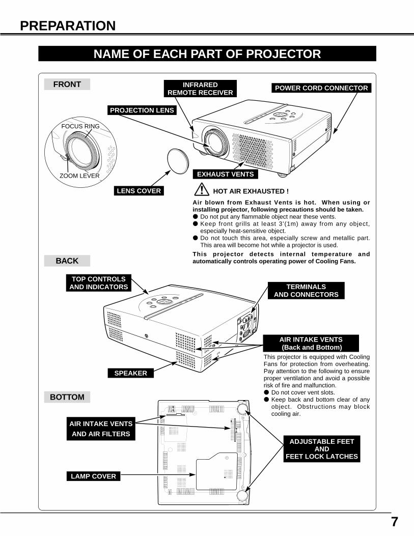
NAME OF EACH PART OF PROJECTOR
BOTTOM
BACK
HOT AIR EXHAUSTED !
Air blown from Exhaust Vents is hot. When using orinstalling projector, following precautions should be taken.● Do not put any flammable object near these vents.● Keep front grills at least 3’(1m) away from any object,
especially heat-sensitive object.● Do not touch this area, especially screw and metallic part.
This area will become hot while a projector is used.
This projector detects internal temperature andautomatically controls operating power of Cooling Fans.
FRONT
This projector is equipped with CoolingFans for protection from overheating.Pay attention to the following to ensureproper ventilation and avoid a possiblerisk of fire and malfunction.● Do not cover vent slots.● Keep back and bottom clear of any
object. Obstructions may blockcooling air.
PROJECTION LENS
LENS COVER
EXHAUST VENTS
INFRARED REMOTE RECEIVER
SPEAKER
POWER CORD CONNECTOR
TERMINALSAND CONNECTORS
TOP CONTROLSAND INDICATORS
LAMP COVER
ADJUSTABLE FEETAND
FEET LOCK LATCHES
AIR INTAKE VENTS
AND AIR FILTERS
AIR INTAKE VENTS(Back and Bottom)
ZOOM LEVER
FOCUS RING
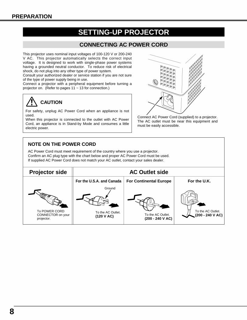
NOTE ON THE POWER CORDAC Power Cord must meet requirement of the country where you use a projector.Confirm an AC plug type with the chart below and proper AC Power Cord must be used.If supplied AC Power Cord does not match your AC outlet, contact your sales dealer.
SETTING-UP PROJECTOR
8
PREPARATION
To POWER CORDCONNECTOR on yourprojector.
Projector side AC Outlet side
Ground
To the AC Outlet.(120 V AC)
For Continental EuropeFor the U.S.A. and Canada
This projector uses nominal input voltages of 100-120 V or 200-240V AC. This projector automatically selects the correct inputvoltage. It is designed to work with single-phase power systemshaving a grounded neutral conductor. To reduce risk of electricalshock, do not plug into any other type of power system.Consult your authorized dealer or service station if you are not sureof the type of power supply being in use.Connect a projector with a peripheral equipment before turning aprojector on. (Refer to pages 11 ~ 13 for connection.)
CAUTION
For safety, unplug AC Power Cord when an appliance is notused.When this projector is connected to the outlet with AC PowerCord, an appliance is in Stand-by Mode and consumes a littleelectric power.
CONNECTING AC POWER CORD
Connect AC Power Cord (supplied) to a projector.The AC outlet must be near this equipment andmust be easily accessible.
For the U.K.
To the AC Outlet.(200 - 240 V AC)
To the AC Outlet.(200 - 240 V AC)
9
PREPARATION
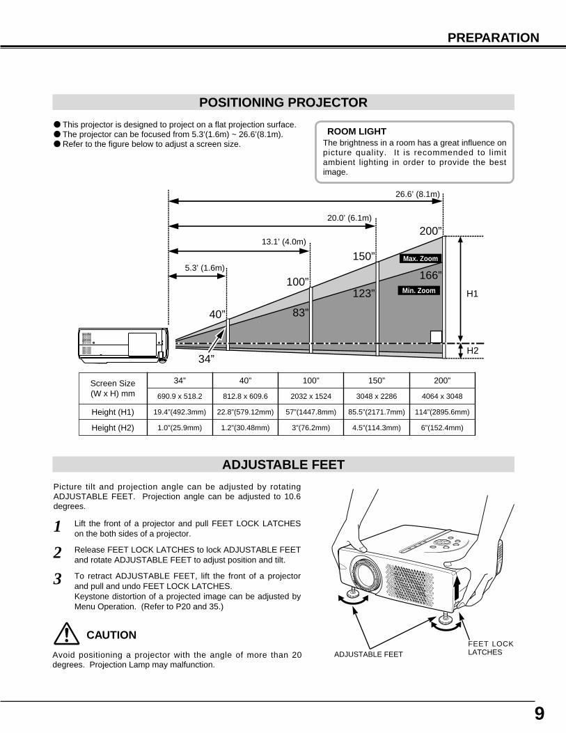
POSITIONING PROJECTOR
● This projector is designed to project on a flat projection surface.● The projector can be focused from 5.3’(1.6m) ~ 26.6’(8.1m).● Refer to the figure below to adjust a screen size.
Screen Size(W x H) mm
Height (H1)
40”
Height (H2)
812.8 x 609.6
22.8”(579.12mm)
1.2”(30.48mm)
100”
2032 x 1524
57”(1447.8mm)
3”(76.2mm)
150”
3048 x 2286
85.5”(2171.7mm)
4.5”(114.3mm)
200”
4064 x 3048
114”(2895.6mm)
6”(152.4mm)
ADJUSTABLE FEET
Picture tilt and projection angle can be adjusted by rotatingADJUSTABLE FEET. Projection angle can be adjusted to 10.6degrees.
Lift the front of a projector and pull FEET LOCK LATCHESon the both sides of a projector.1
ADJUSTABLE FEETFEET LOCKLATCHES
40”
100”
150”
200”
166”
123”
83”
34”
H1
H2
26.6’ (8.1m)
20.0’ (6.1m)
13.1’ (4.0m)
5.3’ (1.6m)
Release FEET LOCK LATCHES to lock ADJUSTABLE FEETand rotate ADJUSTABLE FEET to adjust position and tilt. 2To retract ADJUSTABLE FEET, lift the front of a projectorand pull and undo FEET LOCK LATCHES.Keystone distortion of a projected image can be adjusted byMenu Operation. (Refer to P20 and 35.)
3
ROOM LIGHTThe brightness in a room has a great influence onpicture quality. It is recommended to limitambient lighting in order to provide the bestimage.
Max. Zoom
Min. Zoom
CAUTION
Avoid positioning a projector with the angle of more than 20degrees. Projection Lamp may malfunction.
34”
690.9 x 518.2
19.4”(492.3mm)
1.0”(25.9mm)
10
PREPARATION
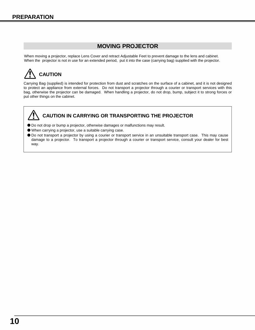
CAUTION IN CARRYING OR TRANSPORTING THE PROJECTOR
● Do not drop or bump a projector, otherwise damages or malfunctions may result.● When carrying a projector, use a suitable carrying case.● Do not transport a projector by using a courier or transport service in an unsuitable transport case. This may cause
damage to a projector. To transport a projector through a courier or transport service, consult your dealer for bestway.
MOVING PROJECTOR
CAUTION
Carrying Bag (supplied) is intended for protection from dust and scratches on the surface of a cabinet, and it is not designedto protect an appliance from external forces. Do not transport a projector through a courier or transport services with thisbag, otherwise the projector can be damaged. When handling a projector, do not drop, bump, subject it to strong forces orput other things on the cabinet.
When moving a projector, replace Lens Cover and retract Adjustable Feet to prevent damage to the lens and cabinet.When the projector is not in use for an extended period, put it into the case (carrying bag) supplied with the projector.
AUDIO OUT
AV
AUDIO IN
COMPUTER
USB
RESETVIDEO
CONTROL PORT S–VIDEO
COMPUTER IN
Y – Pb / Cb – Pr / Cr
11
CONNECTING PROJECTOR
TERMINALS OF PROJECTOR
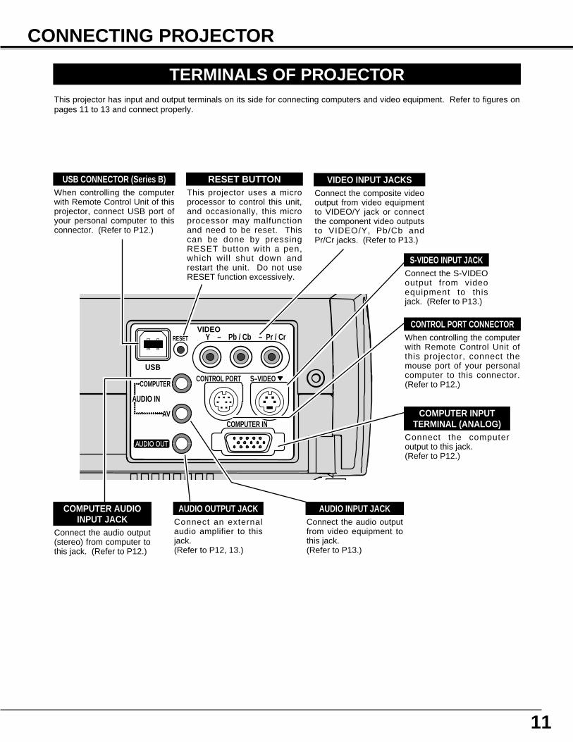
When controlling the computerwith Remote Control Unit ofthis projector, connect themouse port of your personalcomputer to this connector.(Refer to P12.)
Connect the S-VIDEOoutput from videoequipment to thisjack. (Refer to P13.)
Connect the audio output(stereo) from computer tothis jack. (Refer to P12.)
Connect the audio outputfrom video equipment tothis jack.(Refer to P13.)
CONTROL PORT CONNECTOR
COMPUTER AUDIOINPUT JACK
AUDIO INPUT JACK
VIDEO INPUT JACKS
S-VIDEO INPUT JACK
Connect the composite videooutput from video equipmentto VIDEO/Y jack or connectthe component video outputsto VIDEO/Y, Pb/Cb andPr/Cr jacks. (Refer to P13.)
Connect the computeroutput to this jack. (Refer to P12.)
COMPUTER INPUTTERMINAL (ANALOG)
This projector has input and output terminals on its side for connecting computers and video equipment. Refer to figures onpages 11 to 13 and connect properly.
Connect an externalaudio amplifier to thisjack. (Refer to P12, 13.)
AUDIO OUTPUT JACK
This projector uses a microprocessor to control this unit,and occasionally, this microprocessor may malfunctionand need to be reset. Thiscan be done by pressingRESET button with a pen,which wil l shut down andrestart the unit. Do not useRESET function excessively.
RESET BUTTONWhen controlling the computerwith Remote Control Unit of thisprojector, connect USB port ofyour personal computer to thisconnector. (Refer to P12.)
USB CONNECTOR (Series B)
12
CONNECTING PROJECTOR
AUDIO OUT
AV
AUDIO IN
COMPUTER
USB
RESETVIDEO
S–VIDEOCONTROL PORT
COMPUTER IN
Y – Pb / Cb – Pr / Cr
ON
1
DIP
ON
OFF
2 3 4 5 6
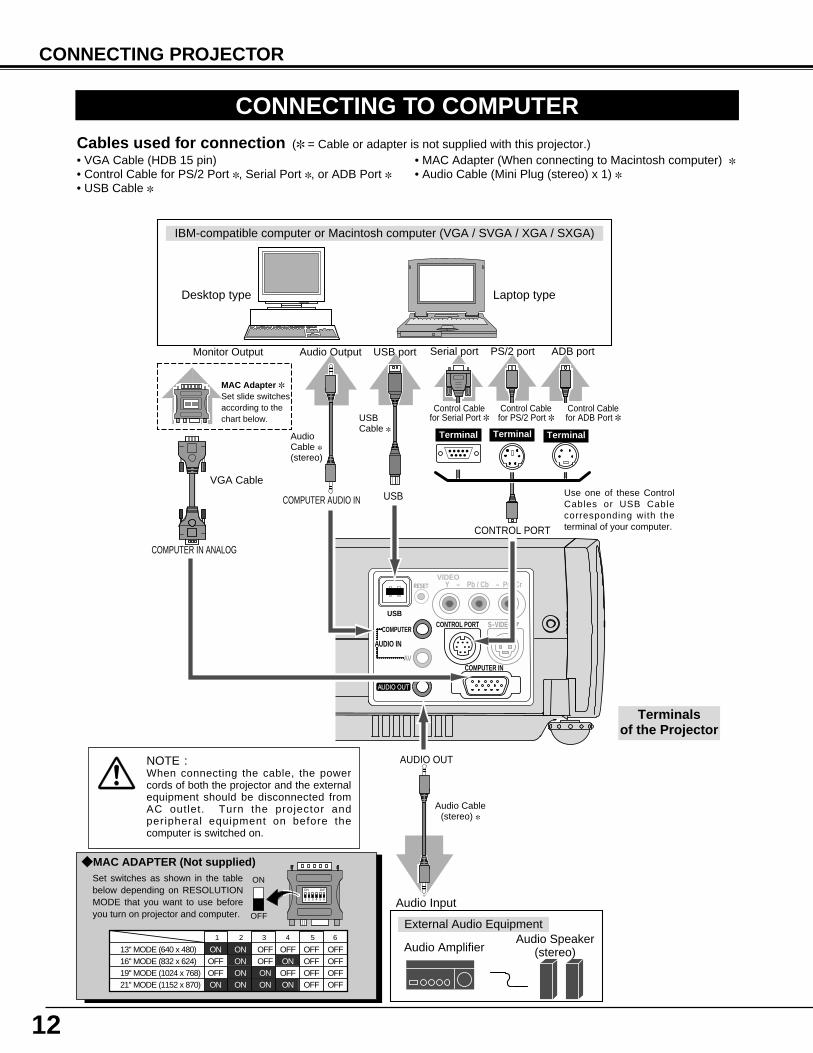
13" MODE (640 x 480)16" MODE (832 x 624)19" MODE (1024 x 768)
OFFON ONON ONON ON
OFF OFF OFFOFFOFF OFF OFF
OFF OFF OFF OFF
1 2 3 4 5 6
OFF OFFON ONON ON21" MODE (1152 x 870)
CONNECTING TO COMPUTER
IBM-compatible computer or Macintosh computer (VGA / SVGA / XGA / SXGA)
VGA Cable
Monitor Output
Desktop type Laptop type
Audio Speaker(stereo)Audio Amplifier
Control Cablefor Serial Port ✽
Audio Cable(stereo) ✽
Terminal
Serial port PS/2 portAudio Output
Audio Input
CONTROL PORT
AUDIO OUT
COMPUTER AUDIO IN
COMPUTER IN ANALOG
Use one of these ControlCables or USB Cablecorresponding with theterminal of your computer.
ADB port
Cables used for connection (✽ = Cable or adapter is not supplied with this projector.)
Control Cablefor PS/2 Port ✽
Control Cablefor ADB Port ✽
Audio Cable ✽(stereo)
NOTE :When connecting the cable, the powercords of both the projector and the externalequipment should be disconnected fromAC outlet. Turn the projector andperipheral equipment on before thecomputer is switched on.
USB port
MAC Adapter ✽Set slide switchesaccording to thechart below.
• VGA Cable (HDB 15 pin)• Control Cable for PS/2 Port ✽ , Serial Port ✽ , or ADB Port ✽• USB Cable ✽
• MAC Adapter (When connecting to Macintosh computer) ✽• Audio Cable (Mini Plug (stereo) x 1) ✽
External Audio Equipment
Terminals of the Projector
Terminal Terminal
USB
Set switches as shown in the tablebelow depending on RESOLUTIONMODE that you want to use beforeyou turn on projector and computer.
◆ MAC ADAPTER (Not supplied)
USB Cable ✽
13
CONNECTING PROJECTOR
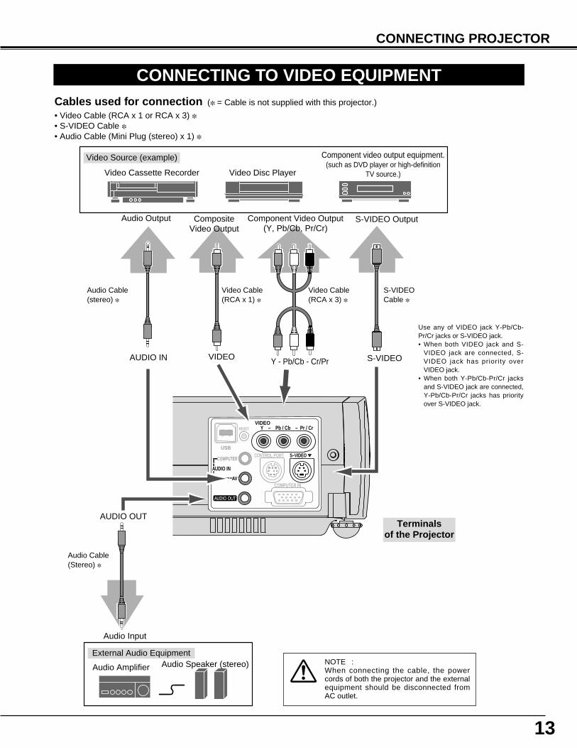
CONNECTING TO VIDEO EQUIPMENT
AUDIO OUT
AV
AUDIO IN
COMPUTER
USB
RESETVIDEO
Y – Pb / Cb – Pr / Cr
S–VIDEO
COMPUTER IN
CONTROL PORT
Video Source (example)
Video Cassette Recorder Video Disc Player
Video Cable(RCA x 1) ✽
S-VIDEOCable ✽
Audio Amplifier Audio Speaker (stereo)
Audio Cable (Stereo) ✽
Terminals of the Projector
Use any of VIDEO jack Y-Pb/Cb-Pr/Cr jacks or S-VIDEO jack.• When both VIDEO jack and S-
VIDEO jack are connected, S-VIDEO jack has priority overVIDEO jack.
• When both Y-Pb/Cb-Pr/Cr jacksand S-VIDEO jack are connected,Y-Pb/Cb-Pr/Cr jacks has priorityover S-VIDEO jack.
S-VIDEO Output
Audio Input
Cables used for connection (✽ = Cable is not supplied with this projector.)
• Video Cable (RCA x 1 or RCA x 3) ✽• S-VIDEO Cable ✽• Audio Cable (Mini Plug (stereo) x 1) ✽
NOTE :When connecting the cable, the powercords of both the projector and the externalequipment should be disconnected fromAC outlet.
Audio Output
Audio Cable(stereo) ✽
External Audio Equipment
AUDIO IN S-VIDEOY - Pb/Cb - Cr/PrVIDEO
AUDIO OUT
Component video output equipment.(such as DVD player or high-definition
TV source.)
CompositeVideo Output
Component Video Output(Y, Pb/Cb, Pr/Cr)
Video Cable(RCA x 3) ✽
+
–
INPUT ON–OFF
KEYSTONE D.ZOOM VOLUME
MENU
NOSHOW FREEZE
AUTO PC ADJ. P–TIMER
MUTE
IMAGE
SELECT
14
BEFORE OPERATION
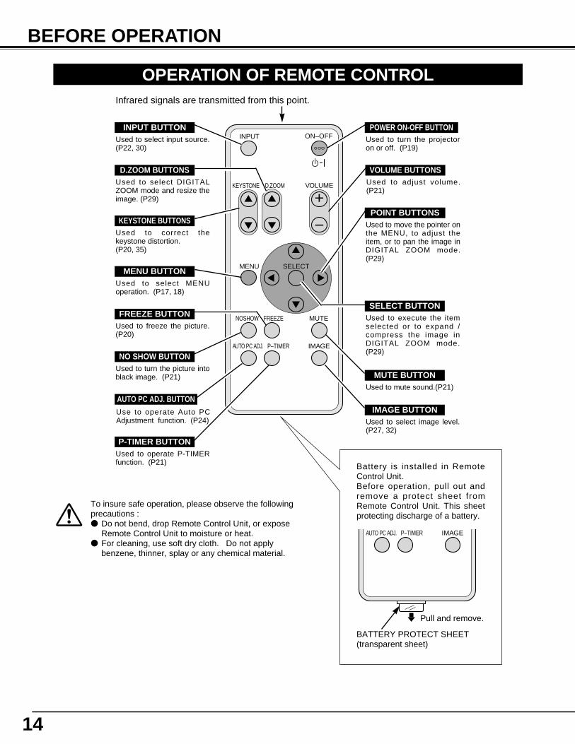
Battery is installed in RemoteControl Unit.Before operation, pull out andremove a protect sheet fromRemote Control Unit. This sheetprotecting discharge of a battery.
AUTO PC ADJ. P–TIMER IMAGE
BATTERY PROTECT SHEET(transparent sheet)
Infrared signals are transmitted from this point.
To insure safe operation, please observe the followingprecautions :● Do not bend, drop Remote Control Unit, or expose
Remote Control Unit to moisture or heat.● For cleaning, use soft dry cloth. Do not apply
benzene, thinner, splay or any chemical material.
MUTE BUTTONUsed to mute sound.(P21)
AUTO PC ADJ. BUTTONUse to operate Auto PCAdjustment function. (P24)
VOLUME BUTTONSUsed to adjust volume.(P21)
D.ZOOM BUTTONSUsed to select DIGITALZOOM mode and resize theimage. (P29)
KEYSTONE BUTTONSUsed to correct thekeystone distortion. (P20, 35)
FREEZE BUTTONUsed to freeze the picture.(P20)
IMAGE BUTTONUsed to select image level.(P27, 32)
OPERATION OF REMOTE CONTROL
Used to select input source.(P22, 30)
POWER ON-OFF BUTTONUsed to turn the projectoron or off. (P19)
MENU BUTTONUsed to select MENUoperation. (P17, 18)
SELECT BUTTON
INPUT BUTTON
Used to execute the itemselected or to expand /compress the image inDIGITAL ZOOM mode.(P29)
Used to move the pointer onthe MENU, to adjust theitem, or to pan the image inDIGITAL ZOOM mode.(P29)
POINT BUTTONS
Used to operate P-TIMERfunction. (P21)
P-TIMER BUTTON
NO SHOW BUTTONUsed to turn the picture intoblack image. (P21)
Pull and remove.
15
BEFORE OPERATION
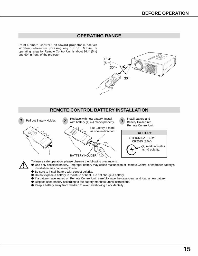
Pull out Battery Holder.Replace with new battery. Installwith battery (+),(–) marks properly.
Install battery andBattery Holder intoRemote Control Unit.
BATTERY
LITHIUM BATTERYCR2025 (3.0V)
(+) mark indicatesits (+) polarity.
Put Battery + markas shown direction.
BATTERY HOLDER
REMOTE CONTROL BATTERY INSTALLATION
To insure safe operation, please observe the following precautions :● Use only specified battery. Improper battery may cause malfunction of Remote Control or improper battery's
installation may cause explosion.● Be sure to install battery with correct polarity.● Do not expose a battery to moisture or heat. Do not charge a battery.● If a battery have leaked on Remote Control Unit, carefully wipe the case clean and load a new battery.● Dispose used battery according to the battery-manufacturer's instructions.● Keep a battery away from children to avoid swallowing it accidentally.
1 2 3
30°
30°
Point Remote Control Unit toward projector (ReceiverWindow) whenever pressing any button. Maximumoperating range for Remote Control Unit is about 16.4’ (5m)and 60° in front of the projector.
16.4’(5 m)
OPERATING RANGE
16
SELECT
IMAGE
MENU
INPUT
ON – OFF
LAMP
READY
WARNINGTEMP .
LAMPREPLACE
-VOLUME-
BEFORE OPERATION
TOP CONTROLS AND INDICATORS
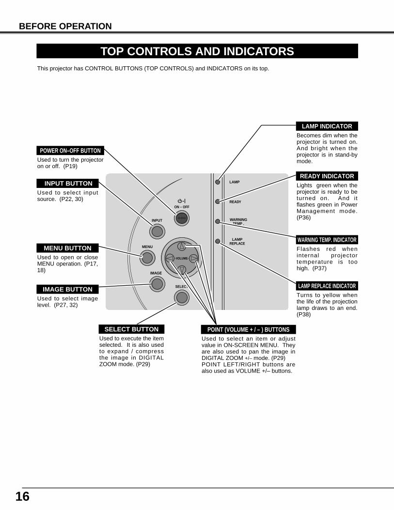
Used to open or closeMENU operation. (P17,18)
MENU BUTTON
IMAGE BUTTON
READY INDICATOR
SELECT BUTTON
POWER ON–OFF BUTTON
INPUT BUTTON
WARNING TEMP. INDICATOR
LAMP INDICATOR
POINT (VOLUME + / – ) BUTTONS
LAMP REPLACE INDICATOR
Used to select imagelevel. (P27, 32)
Lights green when theprojector is ready to beturned on. And itflashes green in PowerManagement mode.(P36)
Becomes dim when theprojector is turned on.And bright when theprojector is in stand-bymode.
Turns to yellow whenthe life of the projectionlamp draws to an end.(P38)
Flashes red wheninternal projectortemperature is toohigh. (P37)
Used to select inputsource. (P22, 30)
Used to select an item or adjustvalue in ON-SCREEN MENU. Theyare also used to pan the image inDIGITAL ZOOM +/– mode. (P29)POINT LEFT/RIGHT buttons arealso used as VOLUME +/– buttons.
Used to execute the itemselected. It is also usedto expand / compressthe image in DIGITALZOOM mode. (P29)
Used to turn the projectoron or off. (P19)
This projector has CONTROL BUTTONS (TOP CONTROLS) and INDICATORS on its top.
17
BEFORE OPERATION
HOW TO OPERATE ON-SCREEN MENU
FLOW OF ON-SCREEN MENU OPERATION
Display ON-SCREEN MENU
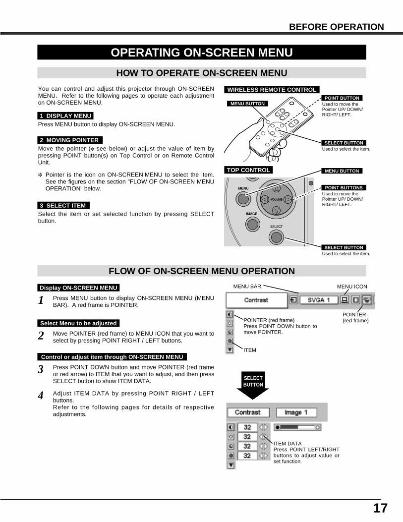
Press MENU button to display ON-SCREEN MENU (MENUBAR). A red frame is POINTER.
Move POINTER (red frame) to MENU ICON that you want toselect by pressing POINT RIGHT / LEFT buttons.
Adjust ITEM DATA by pressing POINT RIGHT / LEFTbuttons.Refer to the following pages for details of respectiveadjustments.
Press POINT DOWN button and move POINTER (red frameor red arrow) to ITEM that you want to adjust, and then pressSELECT button to show ITEM DATA.
Select Menu to be adjusted
Control or adjust item through ON-SCREEN MENU
1
2
4
3
You can control and adjust this projector through ON-SCREENMENU. Refer to the following pages to operate each adjustmenton ON-SCREEN MENU.
2 MOVING POINTER
3 SELECT ITEM
Move the pointer (✽ see below) or adjust the value of item bypressing POINT button(s) on Top Control or on Remote ControlUnit.
Select the item or set selected function by pressing SELECTbutton.
OPERATING ON-SCREEN MENU
✽ Pointer is the icon on ON-SCREEN MENU to select the item.See the figures on the section "FLOW OF ON-SCREEN MENUOPERATION" below.
SELECT
IMAGE
MENU
-VOLUME-
Used to select the item.SELECT BUTTON
Used to move thePointer UP/ DOWN/RIGHT/ LEFT.
POINT BUTTONS
TOP CONTROL
MENU BAR
POINTER(red frame)
MENU ICON
ITEM DATAPress POINT LEFT/RIGHTbuttons to adjust value orset function.
SELECTBUTTON
POINTER (red frame)Press POINT DOWN button tomove POINTER.
1 DISPLAY MENUPress MENU button to display ON-SCREEN MENU.
ITEM
Used to select the item.SELECT BUTTON
Used to move thePointer UP/ DOWN/RIGHT/ LEFT.
POINT BUTTON
WIRELESS REMOTE CONTROL
MENU BUTTON
MENU BUTTON
18
BEFORE OPERATION
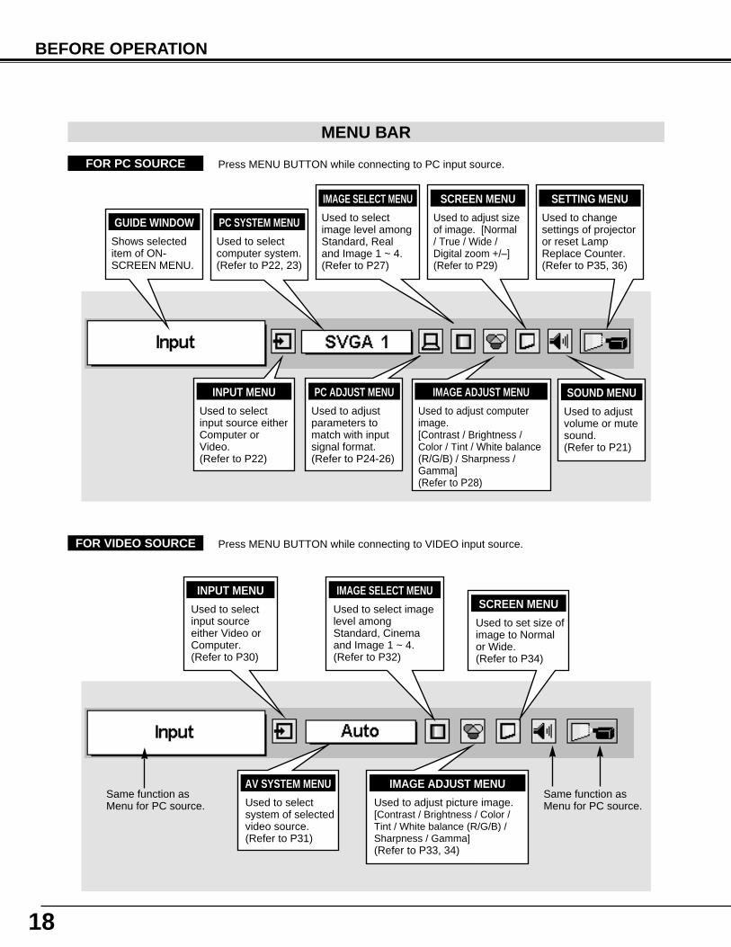
MENU BAR
PC SYSTEM MENU
Used to selectcomputer system.(Refer to P22, 23)
IMAGE ADJUST MENU
Used to adjust computerimage. [Contrast / Brightness /Color / Tint / White balance(R/G/B) / Sharpness /Gamma](Refer to P28)
SETTING MENU
Used to changesettings of projectoror reset LampReplace Counter. (Refer to P35, 36)
SOUND MENU
Used to adjustvolume or mutesound.(Refer to P21)
IMAGE SELECT MENU
Used to selectimage level amongStandard, Realand Image 1 ~ 4.(Refer to P27)
FOR PC SOURCE Press MENU BUTTON while connecting to PC input source.
AV SYSTEM MENU
Used to selectsystem of selectedvideo source.(Refer to P31)
IMAGE ADJUST MENU
Used to adjust picture image. [Contrast / Brightness / Color /Tint / White balance (R/G/B) /Sharpness / Gamma] (Refer to P33, 34)
FOR VIDEO SOURCE Press MENU BUTTON while connecting to VIDEO input source.
Same function asMenu for PC source.
INPUT MENU
Used to selectinput sourceeither Video orComputer.(Refer to P30)
PC ADJUST MENU
Used to adjustparameters tomatch with inputsignal format.(Refer to P24-26)
IMAGE SELECT MENU
Used to select imagelevel amongStandard, Cinemaand Image 1 ~ 4.(Refer to P32)
SCREEN MENU
Used to set size ofimage to Normalor Wide.(Refer to P34)
GUIDE WINDOW
Shows selecteditem of ON-SCREEN MENU.
Same function asMenu for PC source.
INPUT MENU
Used to selectinput source eitherComputer orVideo.(Refer to P22)
SCREEN MENU
Used to adjust sizeof image. [Normal/ True / Wide /Digital zoom +/–](Refer to P29)
19
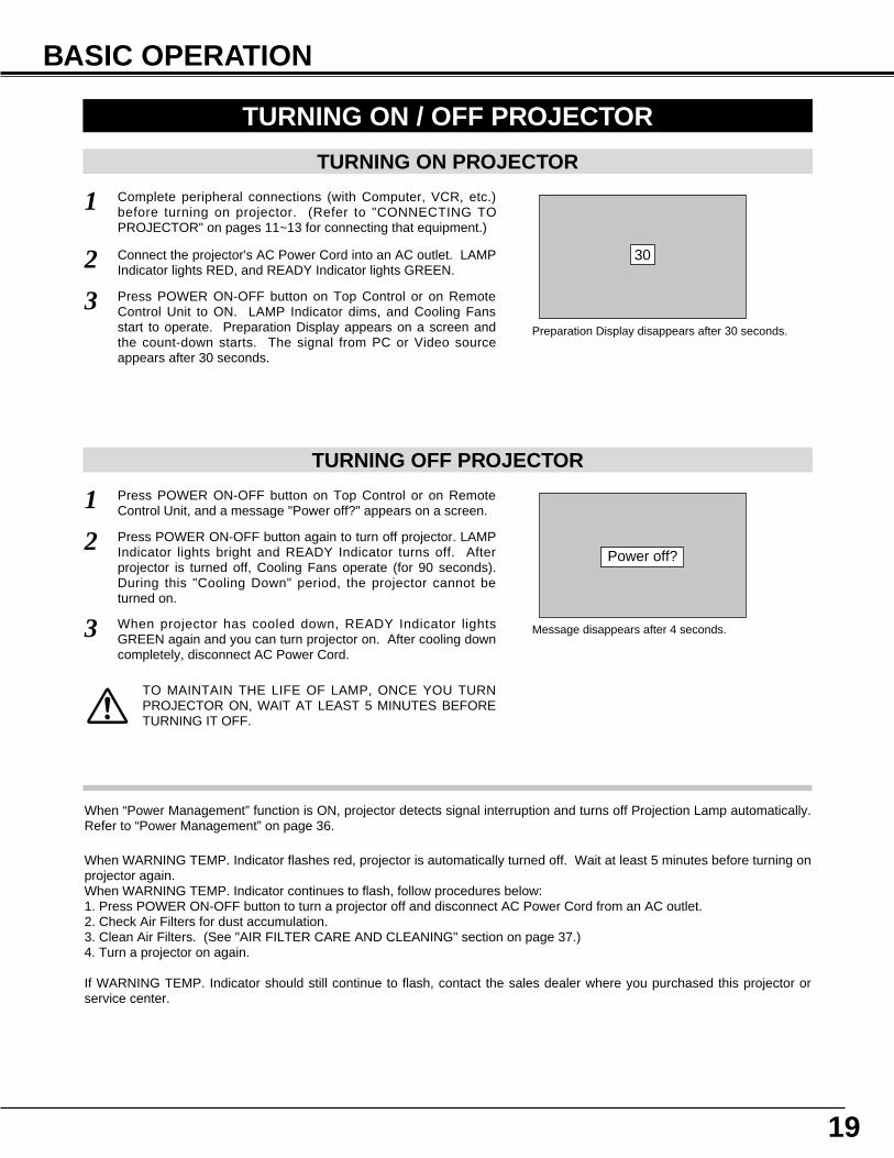
TURNING ON PROJECTOR
Connect the projector's AC Power Cord into an AC outlet. LAMPIndicator lights RED, and READY Indicator lights GREEN.
Press POWER ON-OFF button on Top Control or on RemoteControl Unit to ON. LAMP Indicator dims, and Cooling Fansstart to operate. Preparation Display appears on a screen andthe count-down starts. The signal from PC or Video sourceappears after 30 seconds.
2
3
TURNING OFF PROJECTOR
Press POWER ON-OFF button on Top Control or on RemoteControl Unit, and a message "Power off?" appears on a screen.
Press POWER ON-OFF button again to turn off projector. LAMPIndicator lights bright and READY Indicator turns off. Afterprojector is turned off, Cooling Fans operate (for 90 seconds).During this "Cooling Down" period, the projector cannot beturned on.
1
2
TO MAINTAIN THE LIFE OF LAMP, ONCE YOU TURNPROJECTOR ON, WAIT AT LEAST 5 MINUTES BEFORETURNING IT OFF.
TURNING ON / OFF PROJECTOR
When WARNING TEMP. Indicator flashes red, projector is automatically turned off. Wait at least 5 minutes before turning onprojector again.When WARNING TEMP. Indicator continues to flash, follow procedures below:1. Press POWER ON-OFF button to turn a projector off and disconnect AC Power Cord from an AC outlet.2. Check Air Filters for dust accumulation.3. Clean Air Filters. (See "AIR FILTER CARE AND CLEANING" section on page 37.)4. Turn a projector on again.
If WARNING TEMP. Indicator should still continue to flash, contact the sales dealer where you purchased this projector orservice center.
1 Complete peripheral connections (with Computer, VCR, etc.)before turning on projector. (Refer to "CONNECTING TOPROJECTOR" on pages 11~13 for connecting that equipment.)
3 When projector has cooled down, READY Indicator lightsGREEN again and you can turn projector on. After cooling downcompletely, disconnect AC Power Cord.
30
Preparation Display disappears after 30 seconds.
Power off?
Message disappears after 4 seconds.
When “Power Management” function is ON, projector detects signal interruption and turns off Projection Lamp automatically.Refer to “Power Management” on page 36.
BASIC OPERATION
20
Press FREEZE button on Remote Control Unit to freeze the pictureon-screen. To cancel FREEZE function, press FREEZE button againor press any other button.
PICTURE FREEZE FUNCTION
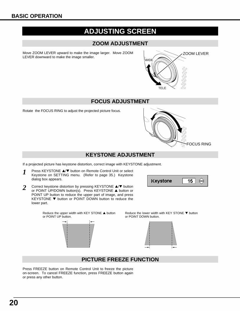
KEYSTONE ADJUSTMENT
1 Press KEYSTONE ▲/▼ button on Remote Control Unit or selectKeystone on SETTING menu. (Refer to page 35.) Keystonedialog box appears.
2 Correct keystone distortion by pressing KEYSTONE ▲/▼ buttonor POINT UP/DOWN button(s). Press KEYSTONE ▲ button orPOINT UP button to reduce the upper part of image, and pressKEYSTONE ▼ button or POINT DOWN button to reduce thelower part.
Reduce the upper width with KEY STONE ▲ buttonor POINT UP button.
Reduce the lower width with KEY STONE ▼ buttonor POINT DOWN button.
If a projected picture has keystone distortion, correct image with KEYSTONE adjustment.
BASIC OPERATION
ADJUSTING SCREEN
ZOOM ADJUSTMENT
FOCUS ADJUSTMENT
Move ZOOM LEVER upward to make the image larger. Move ZOOMLEVER downward to make the image smaller.
Rotate the FOCUS RING to adjust the projected picture focus.
FOCUS RING
WIDE
TELE
ZOOM LEVER
21
BASIC OPERATION
Press NO SHOW button on Remote Control Unit to black out theimage. To restore to normal, press NO SHOW button again or pressany other button.
NO SHOW FUNCTION
Message disappears after 4 seconds.
No show
Press P-TIMER button on Remote Control unit. The timer display “00: 00” appears on the screen and the timer starts to count time (00 : 00~ 59 : 59). To stop P-TIMER display, press P-TIMER button. And then, press P-TIMER button again to cancel P-TIMER function.
P-TIMER FUNCTION
1
2
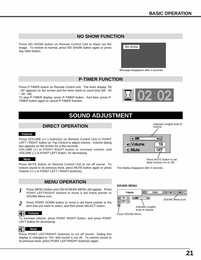
Press MENU button and ON-SCREEN MENU will appear. PressPOINT LEFT/RIGHT buttons to move a red frame pointer toSOUND Menu icon.
Volume
Press VOLUME (+/–) button(s) on Remote Control Unit or POINTLEFT / RIGHT button on Top Control to adjust volume. Volume dialogbox appears on the screen for a few seconds.VOLUME (+) or POINT RIGHT button to increase volume, andVOLUME (–) or POINT LEFT button for decreasing.
Mute
Press MUTE button on Remote Control Unit to cut off sound. Torestore sound to its previous level, press MUTE button again or pressVolume (+/–) or POINT LEFT / RIGHT button(s).
To increase volume, press POINT RIGHT button, and press POINTLEFT button for decreasing.
Press POINT LEFT/RIGHT button(s) to cut off sound. Dialog boxdisplay is changed to “On” and sound is cut off. To restore sound toits previous level, press POINT LEFT/RIGHT button(s) again.
Press POINT DOWN button to move a red frame pointer to theitem that you want to select, and then press SELECT button. Indicates roughly
level of volume.
Close SOUND Menu.
SOUND ADJUSTMENT
DIRECT OPERATION
MENU OPERATION
Volume
Mute
Indicates roughly level ofvolume.
Press MUTE button to setMute function On or Off.
The display disappears after 4 seconds.
SOUND MENU
SOUND Menu icon
22
COMPUTER INPUT
SELECTING INPUT SOURCE
MENU OPERATION
DIRECT OPERATION
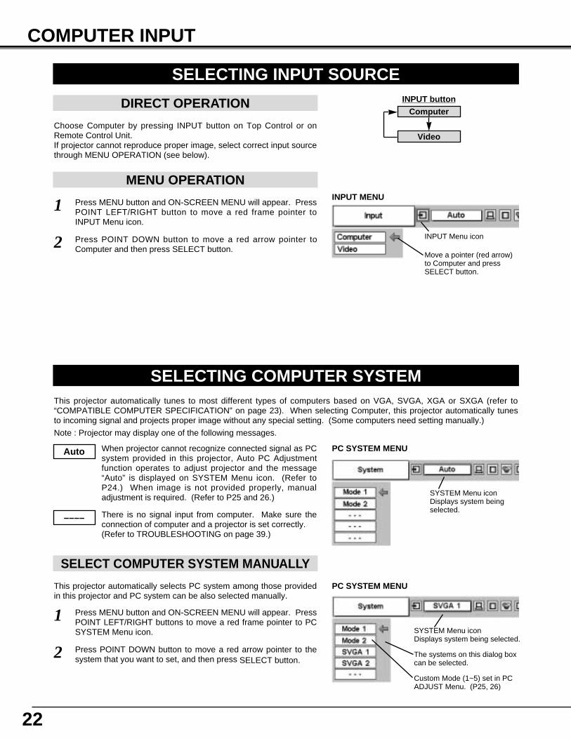
Choose Computer by pressing INPUT button on Top Control or onRemote Control Unit.If projector cannot reproduce proper image, select correct input sourcethrough MENU OPERATION (see below).
Press MENU button and ON-SCREEN MENU will appear. PressPOINT LEFT/RIGHT button to move a red frame pointer toINPUT Menu icon.
Press POINT DOWN button to move a red arrow pointer toComputer and then press SELECT button.
1
2
INPUT buttonComputer
Video
Move a pointer (red arrow)to Computer and pressSELECT button.
INPUT MENU
INPUT Menu icon
SELECTING COMPUTER SYSTEMThis projector automatically tunes to most different types of computers based on VGA, SVGA, XGA or SXGA (refer to“COMPATIBLE COMPUTER SPECIFICATION” on page 23). When selecting Computer, this projector automatically tunesto incoming signal and projects proper image without any special setting. (Some computers need setting manually.)
Note : Projector may display one of the following messages.
When projector cannot recognize connected signal as PCsystem provided in this projector, Auto PC Adjustmentfunction operates to adjust projector and the message“Auto” is displayed on SYSTEM Menu icon. (Refer toP24.) When image is not provided properly, manualadjustment is required. (Refer to P25 and 26.)
There is no signal input from computer. Make sure theconnection of computer and a projector is set correctly. (Refer to TROUBLESHOOTING on page 39.)
Auto
––––
SYSTEM Menu iconDisplays system beingselected.
PC SYSTEM MENU
SELECT COMPUTER SYSTEM MANUALLY
SYSTEM Menu icon Displays system being selected.
The systems on this dialog boxcan be selected.
Press MENU button and ON-SCREEN MENU will appear. PressPOINT LEFT/RIGHT buttons to move a red frame pointer to PCSYSTEM Menu icon.
Press POINT DOWN button to move a red arrow pointer to thesystem that you want to set, and then press SELECT button.
1
2
PC SYSTEM MENU
Custom Mode (1~5) set in PCADJUST Menu. (P25, 26)
This projector automatically selects PC system among those providedin this projector and PC system can be also selected manually.
23
COMPUTER INPUT
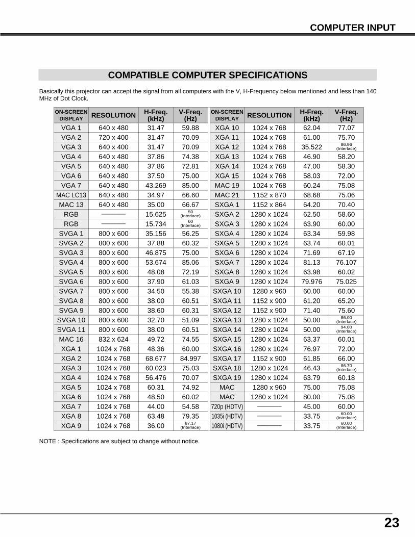
COMPATIBLE COMPUTER SPECIFICATIONS
Basically this projector can accept the signal from all computers with the V, H-Frequency below mentioned and less than 140MHz of Dot Clock.
NOTE : Specifications are subject to change without notice.
ON-SCREENDISPLAY RESOLUTION H-Freq.
(kHz)V-Freq.
(Hz)VGA 1 640 x 480 31.47 59.88VGA 2 720 x 400 31.47 70.09VGA 3 640 x 400 31.47 70.09VGA 4 640 x 480 37.86 74.38VGA 5 640 x 480 37.86 72.81VGA 6 640 x 480 37.50 75.00
MAC LC13 640 x 480 34.97 66.60MAC 13 640 x 480 35.00 66.67
MAC 16 832 x 624 49.72 74.55
MAC 19 1024 x 768 60.24 75.08MAC 21 1152 x 870 68.68 75.06
MAC 1280 x 960 75.00 75.08MAC 1280 x 1024 80.00 75.08
SVGA 1 800 x 600 35.156 56.25SVGA 2 800 x 600 37.88 60.32SVGA 3 800 x 600 46.875 75.00SVGA 4 800 x 600 53.674 85.06SVGA 5 800 x 600 48.08 72.19SVGA 6 800 x 600 37.90 61.03SVGA 7 800 x 600 34.50 55.38SVGA 8 800 x 600 38.00 60.51SVGA 9 800 x 600 38.60 60.31
SVGA 11 800 x 600 38.00 60.51
ON-SCREENDISPLAY RESOLUTION H-Freq.
(kHz)V-Freq.
(Hz)XGA 10 1024 x 768XGA 11 1024 x 768XGA 12 1024 x 768XGA 13 1024 x 768
62.04 77.07
XGA 14 1024 x 768
61.00 75.70
XGA 15 1024 x 768
35.522 86.96(Interlace)
46.90 58.20
XGA 8 1024 x 768
47.00 58.30
XGA 9 1024 x 768
58.03 72.00
SXGA 1 1152 x 864SXGA 2 1280 x 1024
63.48 79.35
SXGA 3 1280 x 1024
36.00 87.17(Interlace)
SXGA 4 1280 x 1024
64.20 70.40
SXGA 5 1280 x 1024
62.50 58.60
SXGA 6 1280 x 1024
63.90 60.00
SXGA 7 1280 x 1024
63.34 59.98
SXGA 8 1280 x 1024
63.74 60.01
SXGA 11 1152 x 900
71.69 67.19
SXGA 12 1152 x 900
81.13 76.107
SXGA 13 1280 x 1024
63.98 60.02
SXGA 14 1280 x 1024
61.20 65.2071.40 75.6050.00 86.00
(Interlace)
720p (HDTV) ––––––––
50.00 94.00(Interlace)
45.00 60.00
XGA 1 1024 x 768XGA 2 1024 x 768XGA 3 1024 x 768XGA 4 1024 x 768
48.36 60.0068.677 84.997
XGA 6 1024 x 768
60.023 75.03
XGA 7 1024 x 768
56.476 70.07
48.50 60.0244.00 54.58
SXGA 9 1280 x 1024SXGA 10 1280 x 960
79.976 75.02560.00 60.00
SXGA 15 1280 x 1024SXGA 16 1280 x 1024SXGA 17 1152 x 900SXGA 18 1280 x 1024
63.37 60.0176.97 72.0061.85 66.0046.43 86.70
(Interlace)
SXGA 19 1280 x 1024 63.79 60.18XGA 5 1024 x 768 60.31 74.92
VGA 7 640 x 480 43.269 85.00
RGB –––––––– 15.734 60(Interlace)
RGB –––––––– 15.625 50(Interlace)
1080i (HDTV) –––––––– 33.75 60.00(Interlace)
1035i (HDTV) –––––––– 33.75 60.00(Interlace)
SVGA 10 800 x 600 32.70 51.09
24
COMPUTER INPUT
PC ADJUSTMENT
AUTO PC ADJUSTMENT
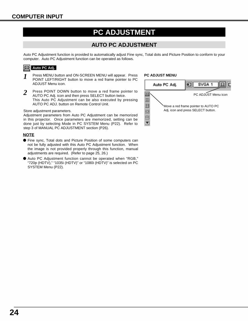
Auto PC Adjustment function is provided to automatically adjust Fine sync, Total dots and Picture Position to conform to yourcomputer. Auto PC Adjustment function can be operated as follows.
Press MENU button and ON-SCREEN MENU will appear. PressPOINT LEFT/RIGHT button to move a red frame pointer to PCADJUST Menu icon.
1
2 Press POINT DOWN button to move a red frame pointer toAUTO PC Adj. icon and then press SELECT button twice.This Auto PC Adjustment can be also executed by pressingAUTO PC ADJ. button on Remote Control Unit.
Move a red frame pointer to AUTO PCAdj. icon and press SELECT button.
PC ADJUST MENU
Auto PC Adj.
PC ADJUST Menu icon
Store adjustment parameters.Adjustment parameters from Auto PC Adjustment can be memorizedin this projector. Once parameters are memorized, setting can bedone just by selecting Mode in PC SYSTEM Menu (P22). Refer tostep 3 of MANUAL PC ADJUSTMENT section (P26).
NOTE● Fine sync, Total dots and Picture Position of some computers can
not be fully adjusted with this Auto PC Adjustment function. Whenthe image is not provided properly through this function, manualadjustments are required. (Refer to page 25, 26.)
● Auto PC Adjustment function cannot be operated when “RGB,”“720p (HDTV),” “1035i (HDTV)” or “1080i (HDTV)” is selected on PCSYSTEM Menu (P22).
25
COMPUTER INPUT
MANUAL PC ADJUSTMENT
This projector can automatically tune to the display signals from most personal computers currently distributed. However,some computers employ special signal formats which are different from the standard ones and may not be tuned by Multi-Scan system of this projector. If this happens, projector cannot reproduce a proper image and the image may be recognizedas a flickering picture, a non-synchronized picture, a non-centered picture or a skewed picture.This projector has a Manual PC Adjustment to enable you to precisely adjust several parameters to match with those specialsignal formats. This projector has 5 independent memory areas to memorize those parameters manually adjusted. Thisenables you to recall the setting for a specific computer whenever you use it.
Note : This PC ADJSUT Menu cannot be operated when "RGB" is selected on PC SYSTEM Menu (P22).
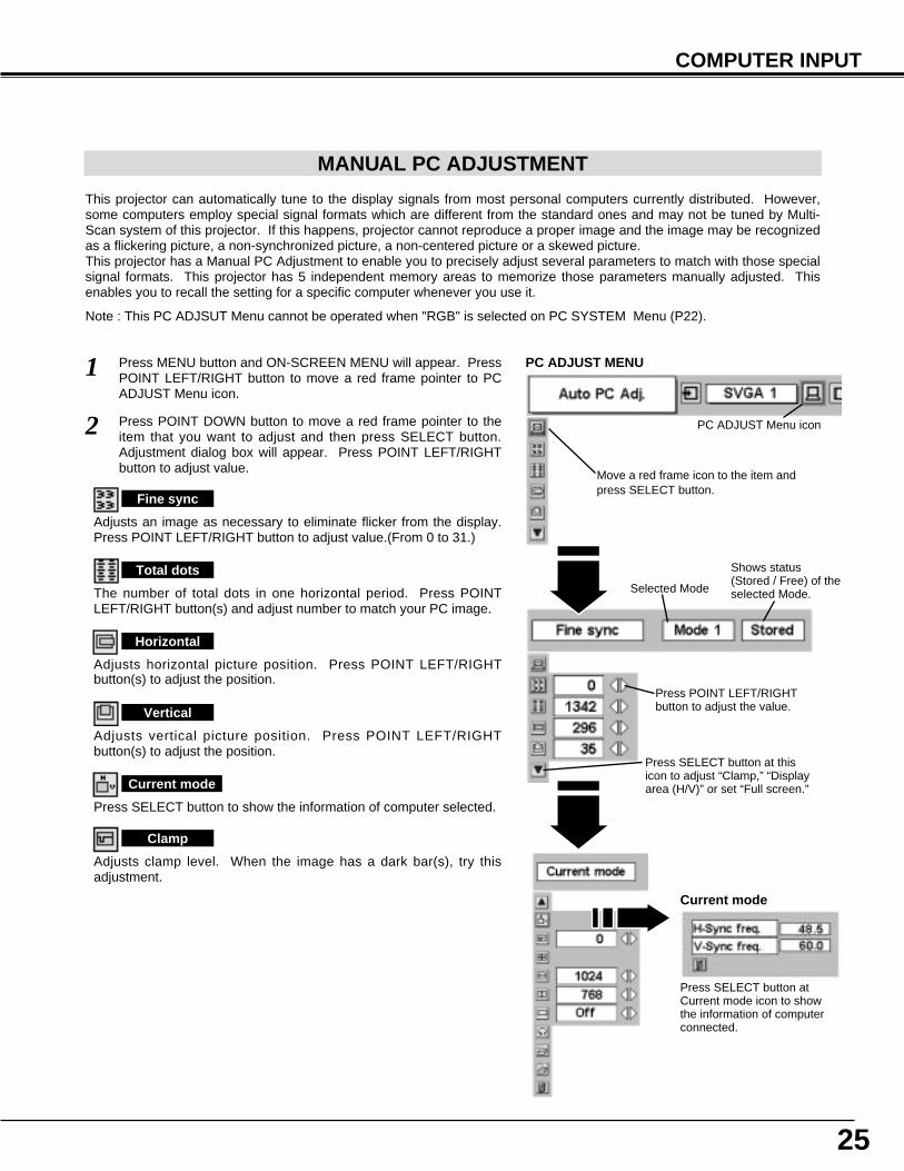
Press MENU button and ON-SCREEN MENU will appear. PressPOINT LEFT/RIGHT button to move a red frame pointer to PCADJUST Menu icon.
1
2 Press POINT DOWN button to move a red frame pointer to theitem that you want to adjust and then press SELECT button.Adjustment dialog box will appear. Press POINT LEFT/RIGHTbutton to adjust value.
Move a red frame icon to the item andpress SELECT button.
PC ADJUST MENU
PC ADJUST Menu icon
Adjusts an image as necessary to eliminate flicker from the display.Press POINT LEFT/RIGHT button to adjust value.(From 0 to 31.)
Fine sync
The number of total dots in one horizontal period. Press POINTLEFT/RIGHT button(s) and adjust number to match your PC image.
Total dots
Adjusts horizontal picture position. Press POINT LEFT/RIGHTbutton(s) to adjust the position.
Horizontal
Adjusts vertical picture position. Press POINT LEFT/RIGHTbutton(s) to adjust the position.
Vertical
Press SELECT button to show the information of computer selected.
Current mode
Adjusts clamp level. When the image has a dark bar(s), try thisadjustment.
Clamp
Press SELECT button at thisicon to adjust “Clamp,” “Displayarea (H/V)” or set “Full screen.”
Press POINT LEFT/RIGHTbutton to adjust the value.
Shows status(Stored / Free) of theselected Mode.Selected Mode
Press SELECT button atCurrent mode icon to showthe information of computerconnected.
Current mode
26
COMPUTER INPUT
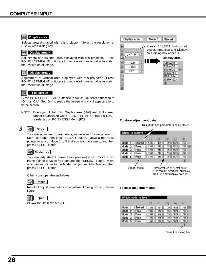
NOTE : Fine sync, Total dots, Display area (H/V) and Full screencannot be adjusted when “1035i (HDTV)” or “1080i (HDTV)”is selected on PC SYSTEM Menu (P22).
Selects area displayed with this projector. Select the resolution atDisplay area dialog box.
Display area
Adjustment of horizontal area displayed with this projector. PressPOINT LEFT/RIGHT button(s) to decrease/increase value to matchthe resolurtion of image.
Display area H
Adjustment of vertical area displayed with this projector. PressPOINT LEFT/RIGHT button(s) to decrease/increase value to matchthe resolurtion of image.
Display area V
Press POINT LEFT/RIGHT button(s) to switch Full screen function to“On” or “Off.” Set “On” to resize the image with 4 x 3 aspect ratio tofit the screen.
Full screen
Reset
Store
Closes PC ADJUST MENU.
Quit
Other icons operates as follows.
3To store adjustment parameters, move a red frame pointer toStore icon and then press SELECT button. Move a red arrowpointer to any of Mode 1 to 5 that you want to store to and thenpress SELECT button.
Reset all adjust parameters on adjustment dialog box to previousfigure.
Mode free
Vacant Mode Shows values of “Total dots,”“Horizontal,” “Vertical,” “Displayarea H,” and “Display area V.”
Close this dialog box.
To store adjustment data.
To clear adjustment data.
To clear adjustment parameters previously set, move a redframe pointer to Mode free icon and then SELECT button. Movea red arrow pointer to the Mode that you want to clear and thenpress SELECT button.
Display area
Press SELECT button atDisplay area icon and Displayarea dialog box appears.
This Mode has parameters being stored.
27
COMPUTER INPUT
PICTURE IMAGE ADJUSTMENT
IMAGE LEVEL SELECT (MENU)
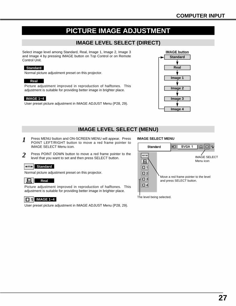
Press MENU button and ON-SCREEN MENU will appear. PressPOINT LEFT/RIGHT button to move a red frame pointer toIMAGE SELECT Menu icon.
1
2 Press POINT DOWN button to move a red frame pointer to thelevel that you want to set and then press SELECT button.
Move a red frame pointer to the leveland press SELECT button.
The level being selected.
IMAGE SELECT MENU
Normal picture adjustment preset on this projector.
Standard
Picture adjustment improved in reproduction of halftones. Thisadjustment is suitable for providing better image in brighter place.
Real
User preset picture adjustment in IMAGE ADJUST Menu (P28, 29).
IMAGE 1~4
IMAGE SELECTMenu icon
IMAGE LEVEL SELECT (DIRECT)
Select image level among Standard, Real, Image 1, Image 2, Image 3and Image 4 by pressing IMAGE button on Top Control or on RemoteControl Unit.
IMAGE buttonStandard
Real
Image 1
Image 2
Image 3
Image 4
Normal picture adjustment preset on this projector.
Picture adjustment improved in reproduction of halftones. Thisadjustment is suitable for providing better image in brighter place.
User preset picture adjustment in IMAGE ADJUST Menu (P28, 29).
Standard
Real
IMAGE 1~4
28
COMPUTER INPUT
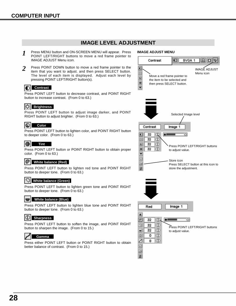
Press POINT LEFT/RIGHT buttonsto adjust value.
Press MENU button and ON-SCREEN MENU will appear. PressPOINT LEFT/RIGHT buttons to move a red frame pointer toIMAGE ADJUST Menu icon.
1
2 Press POINT DOWN button to move a red frame pointer to theitem that you want to adjust. and then press SELECT button.The level of each item is displayed. Adjust each level bypressing POINT LEFT/RIGHT button(s).
Move a red frame pointer tothe item to be selected andthen press SELECT button.
IMAGE ADJUST MENU
IMAGE LEVEL ADJUSTMENT
Store iconPress SELECT button at this icon tostore the adjustment.
IMAGE ADJUSTMenu icon
Selected Image level
Press POINT LEFT button to decrease contrast, and POINT RIGHTbutton to increase contrast. (From 0 to 63.)
Press POINT LEFT button to adjust image darker, and POINTRIGHT button to adjust brighter. (From 0 to 63.)
Contrast
Brightness
Press either POINT LEFT button or POINT RIGHT button to obtainbetter balance of contrast. (From 0 to 15.)
Gamma
Press POINT LEFT button to lighten color, and POINT RIGHT buttonto deeper color. (From 0 to 63.)
Press POINT LEFT button or POINT RIGHT button to obtain propercolor. (From 0 to 63.)
Color
Tint
Press POINT LEFT button to soften the image, and POINT RIGHTbutton to sharpen the image. (From 0 to 15.)
Sharpness
Press POINT LEFT button to lighten red tone and POINT RIGHTbutton to deeper tone. (From 0 to 63.)
White balance (Red)
Press POINT LEFT button to lighten green tone and POINT RIGHTbutton to deeper tone. (From 0 to 63.)
White balance (Green)
Press POINT LEFT button to lighten blue tone and POINT RIGHTbutton to deeper tone. (From 0 to 63.)
White balance (Blue)
Press POINT LEFT/RIGHT buttonsto adjust value.
29
COMPUTER INPUT
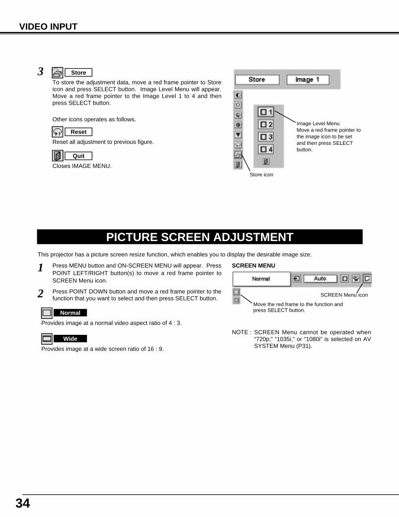
PICTURE SCREEN ADJUSTMENTThis projector has a picture screen resize function, which enables you to display the desirable image size.
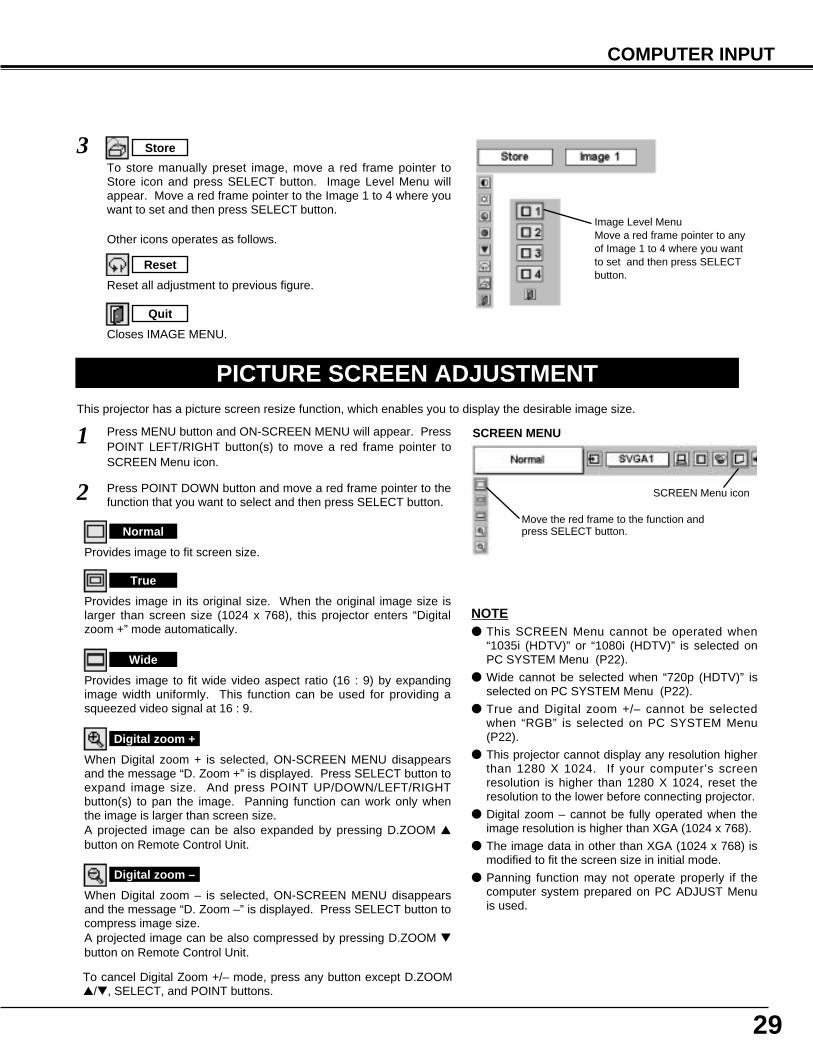
Press MENU button and ON-SCREEN MENU will appear. PressPOINT LEFT/RIGHT button(s) to move a red frame pointer toSCREEN Menu icon.
When Digital zoom + is selected, ON-SCREEN MENU disappearsand the message “D. Zoom +” is displayed. Press SELECT button toexpand image size. And press POINT UP/DOWN/LEFT/RIGHTbutton(s) to pan the image. Panning function can work only whenthe image is larger than screen size.A projected image can be also expanded by pressing D.ZOOM ▲button on Remote Control Unit.
1
To cancel Digital Zoom +/– mode, press any button except D.ZOOM▲/▼, SELECT, and POINT buttons.
Move the red frame to the function andpress SELECT button.
Press POINT DOWN button and move a red frame pointer to thefunction that you want to select and then press SELECT button.2
Wide
Digital zoom +
NOTE● This SCREEN Menu cannot be operated when
“1035i (HDTV)” or “1080i (HDTV)” is selected onPC SYSTEM Menu (P22).
● Wide cannot be selected when “720p (HDTV)” isselected on PC SYSTEM Menu (P22).
● True and Digital zoom +/– cannot be selectedwhen “RGB” is selected on PC SYSTEM Menu(P22).
● This projector cannot display any resolution higherthan 1280 X 1024. If your computer’s screenresolution is higher than 1280 X 1024, reset theresolution to the lower before connecting projector.
● Digital zoom – cannot be fully operated when theimage resolution is higher than XGA (1024 x 768).
● The image data in other than XGA (1024 x 768) ismodified to fit the screen size in initial mode.
● Panning function may not operate properly if thecomputer system prepared on PC ADJUST Menuis used.
Provides image to fit screen size.
Normal
True
SCREEN MENU
SCREEN Menu icon
When Digital zoom – is selected, ON-SCREEN MENU disappearsand the message “D. Zoom –” is displayed. Press SELECT button tocompress image size. A projected image can be also compressed by pressing D.ZOOM ▼button on Remote Control Unit.
Digital zoom –
Provides image in its original size. When the original image size islarger than screen size (1024 x 768), this projector enters “Digitalzoom +” mode automatically.
Provides image to fit wide video aspect ratio (16 : 9) by expandingimage width uniformly. This function can be used for providing asqueezed video signal at 16 : 9.
Image Level MenuMove a red frame pointer to anyof Image 1 to 4 where you wantto set and then press SELECTbutton.
Reset all adjustment to previous figure.
Reset
Store
Closes IMAGE MENU.
Quit
Other icons operates as follows.
3To store manually preset image, move a red frame pointer toStore icon and press SELECT button. Image Level Menu willappear. Move a red frame pointer to the Image 1 to 4 where youwant to set and then press SELECT button.
30
VIDEO INPUT
SELECTING INPUT SOURCE
MENU OPERATION
DIRECT OPERATION
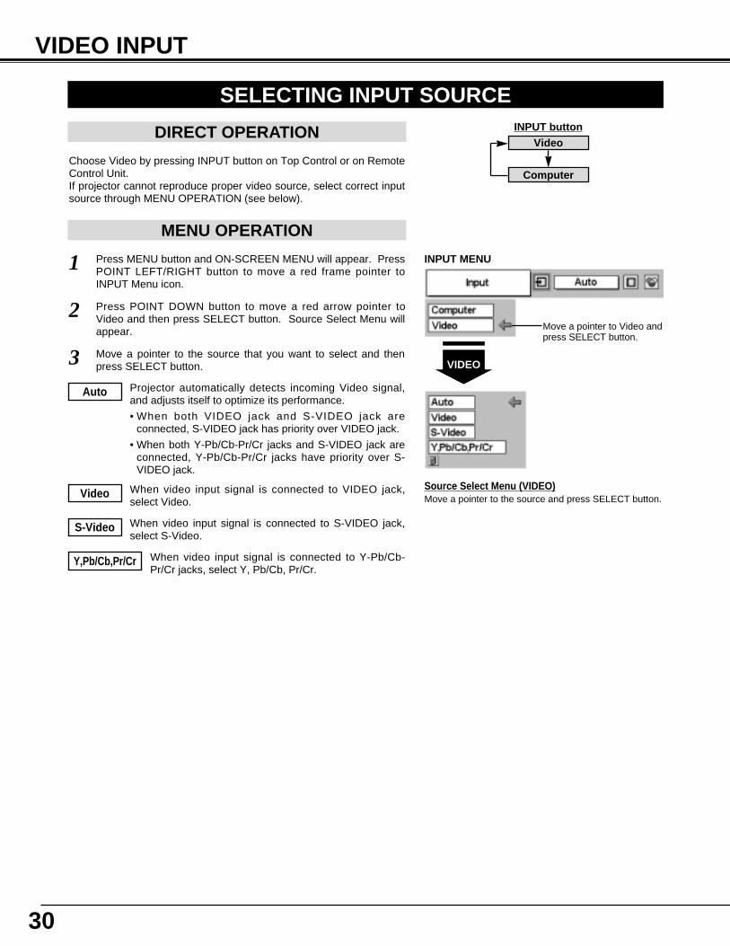
Choose Video by pressing INPUT button on Top Control or on RemoteControl Unit.If projector cannot reproduce proper video source, select correct inputsource through MENU OPERATION (see below).
Press MENU button and ON-SCREEN MENU will appear. PressPOINT LEFT/RIGHT button to move a red frame pointer toINPUT Menu icon.
Press POINT DOWN button to move a red arrow pointer toVideo and then press SELECT button. Source Select Menu willappear.
1
2Move a pointer to Video andpress SELECT button.
VIDEO
Move a pointer to the source and press SELECT button.Source Select Menu (VIDEO)
INPUT MENU
INPUT buttonVideo
Computer
Move a pointer to the source that you want to select and thenpress SELECT button.3
Projector automatically detects incoming Video signal,and adjusts itself to optimize its performance.
• When both VIDEO jack and S-VIDEO jack areconnected, S-VIDEO jack has priority over VIDEO jack.
• When both Y-Pb/Cb-Pr/Cr jacks and S-VIDEO jack areconnected, Y-Pb/Cb-Pr/Cr jacks have priority over S-VIDEO jack.
Auto
When video input signal is connected to VIDEO jack,select Video.
Video
When video input signal is connected to S-VIDEO jack,select S-Video.
S-Video
When video input signal is connected to Y-Pb/Cb-Pr/Cr jacks, select Y, Pb/Cb, Pr/Cr.
Y,Pb/Cb,Pr/Cr
31
VIDEO INPUT
AV SYSTEM MENU (VIDEO OR S-VIDEO)
AV SYSTEM MENU (COMPONENT VIDEO)
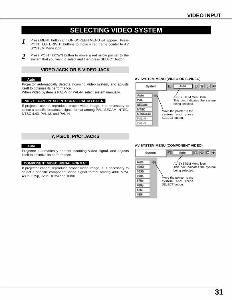
SELECTING VIDEO SYSTEMPress MENU button and ON-SCREEN MENU will appear. PressPOINT LEFT/RIGHT buttons to move a red frame pointer to AVSYSTEM Menu icon.
Press POINT DOWN button to move a red arrow pointer to thesystem that you want to select and then press SELECT button.
1
2
If projector cannot reproduce proper video image, it is necessary toselect a specific broadcast signal format among PAL, SECAM, NTSC,NTSC 4.43, PAL-M, and PAL-N.
Move the pointer to thesystem and pressSELECT button.
PAL / SECAM / NTSC / NTSC4.43 / PAL-M / PAL-N
Projector automatically detects incoming Video signal, and adjustsitself to optimize its performance.
If projector cannot reproduce proper video image, it is necessary toselect a specific component video signal format among 480i, 575i,480p, 575p, 720p, 1035i and 1080i.
Auto
COMPONENT VIDEO SIGNAL FORMAT
VIDEO JACK OR S-VIDEO JACK
Y, Pb/Cb, Pr/Cr JACKS
Projector automatically detects incoming Video system, and adjustsitself to optimize its performance.When Video System is PAL-M or PAL-N, select system manually.
Auto
AV SYSTEM Menu iconThis box indicates the systembeing selected.
Move the pointer to thesystem and pressSELECT button.
AV SYSTEM Menu iconThis box indicates the systembeing selected.
32
VIDEO INPUT
PICTURE IMAGE ADJUSTMENT
IMAGE LEVEL SELECT (MENU)
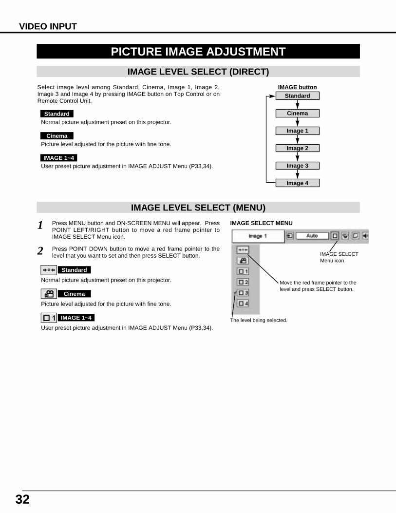
Press MENU button and ON-SCREEN MENU will appear. PressPOINT LEFT/RIGHT button to move a red frame pointer toIMAGE SELECT Menu icon.
1
2 Press POINT DOWN button to move a red frame pointer to thelevel that you want to set and then press SELECT button.
Move the red frame pointer to thelevel and press SELECT button.
The level being selected.
IMAGE SELECT MENU
Normal picture adjustment preset on this projector.
Standard
Picture level adjusted for the picture with fine tone.
Cinema
User preset picture adjustment in IMAGE ADJUST Menu (P33,34).
IMAGE 1~4
IMAGE SELECTMenu icon
IMAGE LEVEL SELECT (DIRECT)
Select image level among Standard, Cinema, Image 1, Image 2,Image 3 and Image 4 by pressing IMAGE button on Top Control or onRemote Control Unit.
Normal picture adjustment preset on this projector. Standard
Picture level adjusted for the picture with fine tone.Cinema
User preset picture adjustment in IMAGE ADJUST Menu (P33,34).IMAGE 1~4
IMAGE buttonStandard
Cinema
Image 1
Image 2
Image 3
Image 4
33
VIDEO INPUT
Press POINT LEFT/RIGHT buttonsto adjust value.
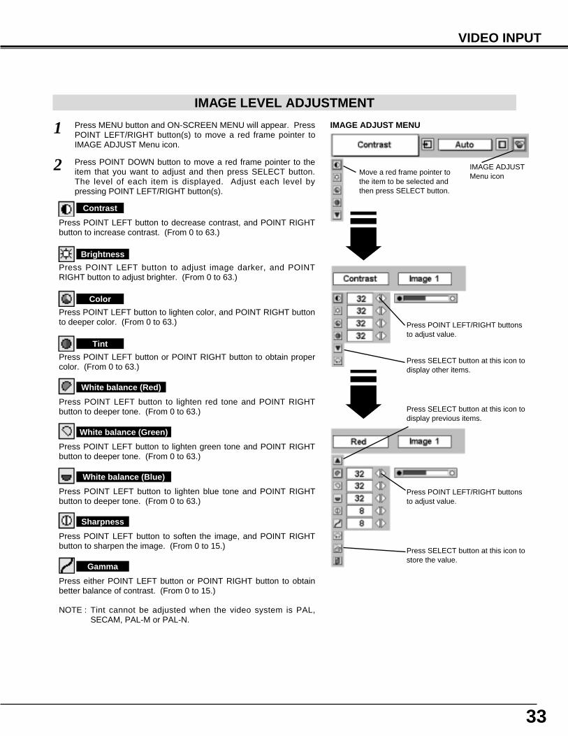
Press MENU button and ON-SCREEN MENU will appear. PressPOINT LEFT/RIGHT button(s) to move a red frame pointer toIMAGE ADJUST Menu icon.
1
2 Press POINT DOWN button to move a red frame pointer to theitem that you want to adjust and then press SELECT button.The level of each item is displayed. Adjust each level bypressing POINT LEFT/RIGHT button(s).
Move a red frame pointer tothe item to be selected andthen press SELECT button.
IMAGE ADJUST MENU
IMAGE LEVEL ADJUSTMENT
Press POINT LEFT button to decrease contrast, and POINT RIGHTbutton to increase contrast. (From 0 to 63.)
Press POINT LEFT button to adjust image darker, and POINTRIGHT button to adjust brighter. (From 0 to 63.)
Contrast
Brightness
Press either POINT LEFT button or POINT RIGHT button to obtainbetter balance of contrast. (From 0 to 15.)
Gamma
Press SELECT button at this icon todisplay other items.
IMAGE ADJUSTMenu icon
Press POINT LEFT/RIGHT buttonsto adjust value.
Press POINT LEFT button to lighten color, and POINT RIGHT buttonto deeper color. (From 0 to 63.)
Press POINT LEFT button or POINT RIGHT button to obtain propercolor. (From 0 to 63.)
Color
Tint
Press POINT LEFT button to soften the image, and POINT RIGHTbutton to sharpen the image. (From 0 to 15.)
Sharpness
Press POINT LEFT button to lighten red tone and POINT RIGHTbutton to deeper tone. (From 0 to 63.)
White balance (Red)
Press POINT LEFT button to lighten green tone and POINT RIGHTbutton to deeper tone. (From 0 to 63.)
White balance (Green)
Press POINT LEFT button to lighten blue tone and POINT RIGHTbutton to deeper tone. (From 0 to 63.)
White balance (Blue)
NOTE : Tint cannot be adjusted when the video system is PAL,SECAM, PAL-M or PAL-N.
Press SELECT button at this icon tostore the value.
Press SELECT button at this icon todisplay previous items.
34
VIDEO INPUT
PICTURE SCREEN ADJUSTMENTThis projector has a picture screen resize function, which enables you to display the desirable image size.
Press MENU button and ON-SCREEN MENU will appear. PressPOINT LEFT/RIGHT button(s) to move a red frame pointer toSCREEN Menu icon.
Press POINT DOWN button and move a red frame pointer to thefunction that you want to select and then press SELECT button.
1
2
NOTE : SCREEN Menu cannot be operated when“720p,” “1035i,” or “1080i” is selected on AVSYSTEM Menu (P31).
Move the red frame to the function andpress SELECT button.
SCREEN MENU
SCREEN Menu icon
Provides image at a wide screen ratio of 16 : 9.
Wide
Provides image at a normal video aspect ratio of 4 : 3.
Normal
3To store the adjustment data, move a red frame pointer to Storeicon and press SELECT button. Image Level Menu will appear.Move a red frame pointer to the Image Level 1 to 4 and thenpress SELECT button.
Image Level MenuMove a red frame pointer tothe image icon to be setand then press SELECTbutton.
Store icon
Reset all adjustment to previous figure.
Reset
Store
Closes IMAGE MENU.
Quit
Other icons operates as follows.
35
SETTING
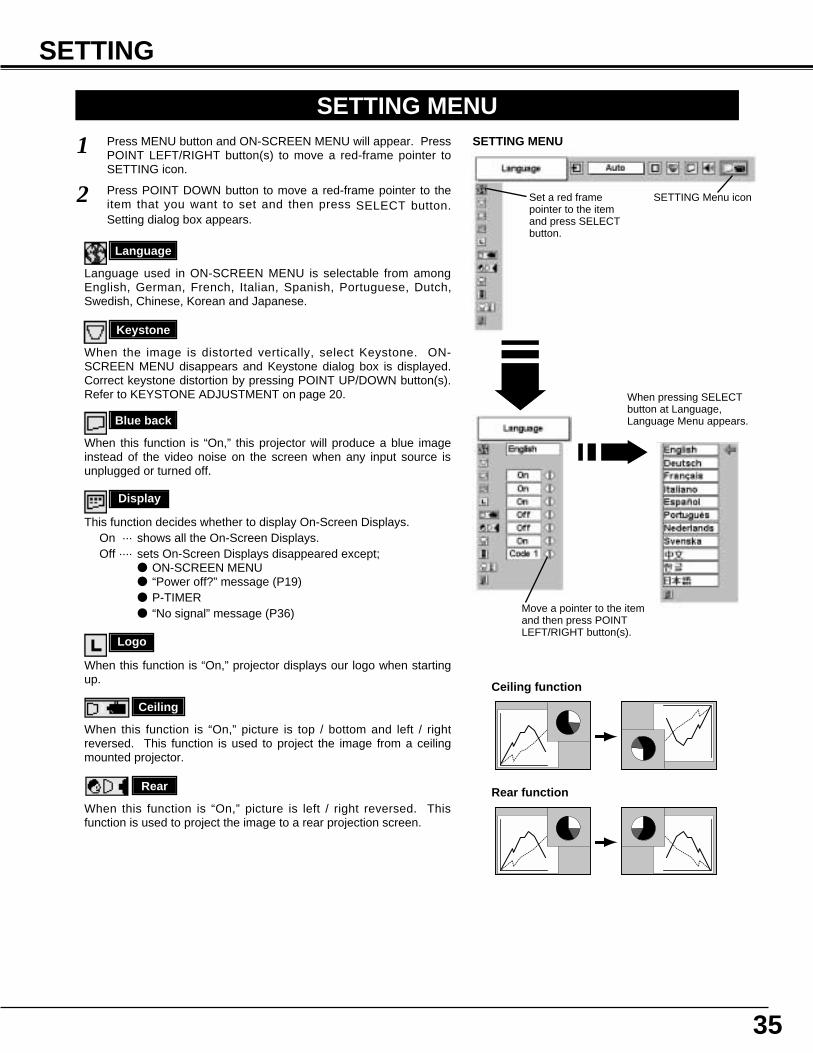
Ceiling
When this function is “On,” picture is top / bottom and left / rightreversed. This function is used to project the image from a ceilingmounted projector.
Rear
When this function is “On,” picture is left / right reversed. Thisfunction is used to project the image to a rear projection screen.
Ceiling function
Rear function
Keystone
When the image is distorted vertically, select Keystone. ON-SCREEN MENU disappears and Keystone dialog box is displayed.Correct keystone distortion by pressing POINT UP/DOWN button(s).Refer to KEYSTONE ADJUSTMENT on page 20.
SETTING MENUPress MENU button and ON-SCREEN MENU will appear. PressPOINT LEFT/RIGHT button(s) to move a red-frame pointer toSETTING icon.
1
2
Language
Language used in ON-SCREEN MENU is selectable from amongEnglish, German, French, Italian, Spanish, Portuguese, Dutch,Swedish, Chinese, Korean and Japanese.
Display
This function decides whether to display On-Screen Displays.On ··· shows all the On-Screen Displays.Off ···· sets On-Screen Displays disappeared except;
● ON-SCREEN MENU ● “Power off?” message (P19)● P-TIMER● “No signal” message (P36)
Set a red framepointer to the itemand press SELECTbutton.
Press POINT DOWN button to move a red-frame pointer to theitem that you want to set and then press SELECT button.Setting dialog box appears.
Blue back
When this function is “On,” this projector will produce a blue imageinstead of the video noise on the screen when any input source isunplugged or turned off.
Logo
When this function is “On,” projector displays our logo when startingup.
When pressing SELECTbutton at Language,Language Menu appears.
Move a pointer to the itemand then press POINTLEFT/RIGHT button(s).
SETTING MENU
SETTING Menu icon
36
SETTING
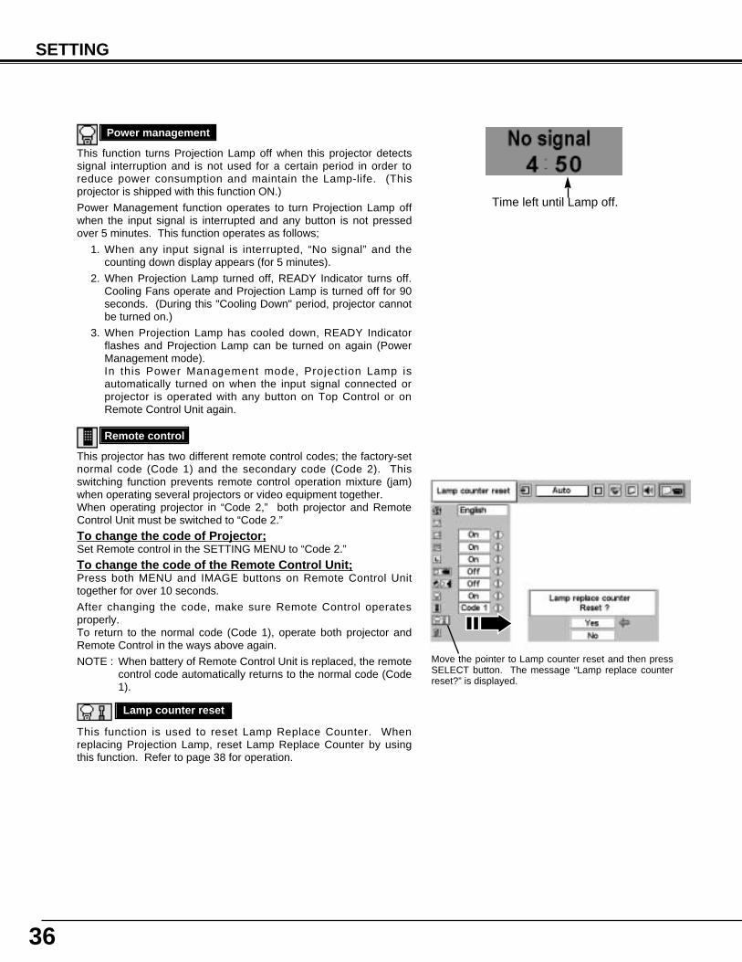
This function turns Projection Lamp off when this projector detectssignal interruption and is not used for a certain period in order toreduce power consumption and maintain the Lamp-life. (Thisprojector is shipped with this function ON.)
Power Management function operates to turn Projection Lamp offwhen the input signal is interrupted and any button is not pressedover 5 minutes. This function operates as follows;
1. When any input signal is interrupted, “No signal” and thecounting down display appears (for 5 minutes).
2. When Projection Lamp turned off, READY Indicator turns off.Cooling Fans operate and Projection Lamp is turned off for 90seconds. (During this "Cooling Down" period, projector cannotbe turned on.)
3. When Projection Lamp has cooled down, READY Indicatorflashes and Projection Lamp can be turned on again (PowerManagement mode). In this Power Management mode, Projection Lamp isautomatically turned on when the input signal connected orprojector is operated with any button on Top Control or onRemote Control Unit again.
Power management
This function is used to reset Lamp Replace Counter. Whenreplacing Projection Lamp, reset Lamp Replace Counter by usingthis function. Refer to page 38 for operation.
Lamp counter reset
Remote control
This projector has two different remote control codes; the factory-setnormal code (Code 1) and the secondary code (Code 2). Thisswitching function prevents remote control operation mixture (jam)when operating several projectors or video equipment together. When operating projector in “Code 2,” both projector and RemoteControl Unit must be switched to “Code 2.”
To change the code of Projector;Set Remote control in the SETTING MENU to “Code 2.”
To change the code of the Remote Control Unit;Press both MENU and IMAGE buttons on Remote Control Unittogether for over 10 seconds.
After changing the code, make sure Remote Control operatesproperly. To return to the normal code (Code 1), operate both projector andRemote Control in the ways above again.
NOTE : When battery of Remote Control Unit is replaced, the remotecontrol code automatically returns to the normal code (Code1).
Time left until Lamp off.
Move the pointer to Lamp counter reset and then pressSELECT button. The message “Lamp replace counterreset?” is displayed.
37
APPENDIX
CLEANING PROJECTION LENS
Apply a non-abrasive camera lens cleaner to a soft, dry cleaning cloth. Avoid using an excessive amount of cleaner.Abrasive cleaners, solvents or other harsh chemicals might scratch a surface.
When the projector is not in use, replace Lens Cover.
1
3
Lightly wipe a cleaning cloth over Projection Lens.2
Follow these steps to clean Projection Lens:
MAINTENANCE
WARNING TEMP. INDICATOR
WARNING TEMP. Indicator flashes red when an internal temperature of a projector exceeds the normal temperature. ThisIndicator stops flashing when the temperature of a projector returns to normal.When WARNING TEMP. Indicator continues to flash, check the items listed below.
Ventilation Slots of the projector may be blocked. In such an event, reposition the projector so that Ventilation Slotsare not obstructed.
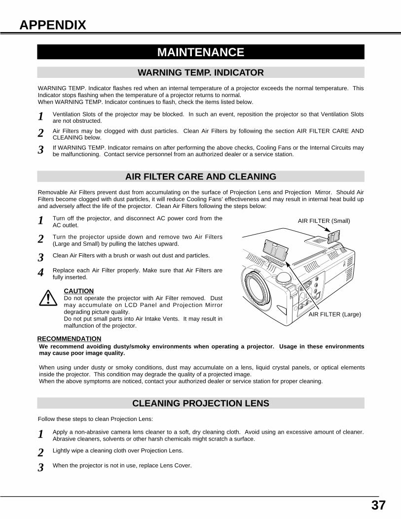
AIR FILTER CARE AND CLEANING
Air Filters may be clogged with dust particles. Clean Air Filters by following the section AIR FILTER CARE ANDCLEANING below.
12
If WARNING TEMP. Indicator remains on after performing the above checks, Cooling Fans or the Internal Circuits maybe malfunctioning. Contact service personnel from an authorized dealer or a service station.3
AIR FILTER (Large)
Turn off the projector, and disconnect AC power cord from theAC outlet.
Turn the projector upside down and remove two Air Filters(Large and Small) by pulling the latches upward.
1
2
Removable Air Filters prevent dust from accumulating on the surface of Projection Lens and Projection Mirror. Should AirFilters become clogged with dust particles, it will reduce Cooling Fans’ effectiveness and may result in internal heat build upand adversely affect the life of the projector. Clean Air Filters following the steps below:
Clean Air Filters with a brush or wash out dust and particles.3Replace each Air Filter properly. Make sure that Air Filters arefully inserted.4
CAUTIONDo not operate the projector with Air Filter removed. Dustmay accumulate on LCD Panel and Projection Mirrordegrading picture quality.Do not put small parts into Air Intake Vents. It may result inmalfunction of the projector.
RECOMMENDATIONWe recommend avoiding dusty/smoky environments when operating a projector. Usage in these environmentsmay cause poor image quality.
When using under dusty or smoky conditions, dust may accumulate on a lens, liquid crystal panels, or optical elementsinside the projector. This condition may degrade the quality of a projected image.When the above symptoms are noticed, contact your authorized dealer or service station for proper cleaning.
AIR FILTER (Small)
38
APPENDIX
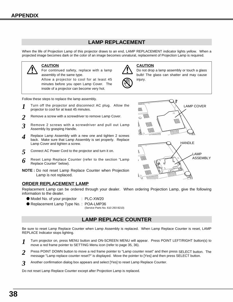
LAMP REPLACEMENT
When the life of Projection Lamp of this projector draws to an end, LAMP REPLACEMENT indicator lights yellow. When aprojected image becomes dark or the color of an image becomes unnatural, replacement of Projection Lamp is required.
Turn off the projector and disconnect AC plug. Allow theprojector to cool for at least 45 minutes.
Remove 2 screws with a screwdriver and pull out LampAssembly by grasping Handle.
1
3Replace Lamp Assembly with a new one and tighten 2 screwsback. Make sure that Lamp Assembly is set properly. ReplaceLamp Cover and tighten a screw.
4
Remove a screw with a screwdriver to remove Lamp Cover.2
Connect AC Power Cord to the projector and turn it on.
6
Follow these steps to replace the lamp assembly.
Reset Lamp Replace Counter (refer to the section “LampReplace Counter” below).
5 LAMPASSEMBLY
HANDLE
LAMP COVER
NOTE : Do not reset Lamp Replace Counter when ProjectionLamp is not replaced.
ORDER REPLACEMENT LAMPReplacement Lamp can be ordered through your dealer. When ordering Projection Lamp, give the followinginformation to the dealer.
● Model No. of your projector : PLC-XW20 ● Replacement Lamp Type No. : POA-LMP36
(Service Parts No. 610 293 8210)
LAMP REPLACE COUNTER
Be sure to reset Lamp Replace Counter when Lamp Assembly is replaced. When Lamp Replace Counter is reset, LAMPREPLACE Indicator stops lighting.
Turn projector on, press MENU button and ON-SCREEN MENU will appear. Press POINT LEFT/RIGHT button(s) tomove a red frame pointer to SETTING Menu icon (refer to page 35, 36).
1Press POINT DOWN button to move a red frame pointer to “Lamp counter reset” and then press SELECT button. Themessage "Lamp replace counter reset?" is displayed. Move the pointer to [Yes] and then press SELECT button.
2
Do not reset Lamp Replace Counter except after Projection Lamp is replaced.
Another confirmation dialog box appears and select [Yes] to reset Lamp Replace Counter.3
CAUTIONDo not drop a lamp assembly or touch a glassbulb! The glass can shatter and may causeinjury.
CAUTIONFor continued safety, replace with a lampassembly of the same type.Allow a projector to cool for at least 45minutes before you open Lamp Cover. Theinside of a projector can become very hot.
39
APPENDIX
TROUBLESHOOTINGBefore calling your dealer or service center for assistance, check the matters below once again.
1. Make sure you have connected a projector to your computer or video equipment as described in the section"CONNECTING THE PROJECTOR" on pages 11 ~ 13.
2. Check cable connection. Verify that all computer, video and power cord are properly connected.3. Verify that all power is switched on.4. If a projector still does not produce an image, re-start your computer.5. If an image still does not appear, unplug a projector from your computer and check your computer monitor's display. The
problem may be with your graphics controller rather than with a projector. (When you reconnect a projector, be sure toturn the computer and monitor off before you power up the projector. Power the equipment back on in order of : Projectorand computer.)
6. If the problem still exists, check following chart.
No power. ● Plug a projector into your AC outlet.● Make sure READY Indicator lights.● Wait 90 seconds after a projector is turned OFF when turning the projector back on.
NOTE : After pressing Power ON-OFF button to OFF, make sure a projector works asfollows:
1. LAMP indicator lights bright and READY indicator turns off.2. After 90 seconds, READY indicator lights green again and a projector may be
turned on by pressing Power ON-OFF button.
● Check WARNING TEMP. indicator. If the indicator flashes red, the projector cannot beturned on.(See "TURNING ON/OFF PROJECTOR" section on page 19.)
● Check Projection Lamp. (Refer to page 38.)
Image is out offocus.
● Adjust focus of a projector.● Make sure a projection screen is at least 5.3’ (1.6m) from the projector.● Check Projection Lens to see if it needs cleaning.
NOTE : Moving a projector from a cool temperature location to a warm temperature locationmay result in moisture condensation on Projection Lens. In such an event, leave aprojector OFF and wait until condensation disappears.
Picture is Left/Rightreversed.
● Check Ceiling / Rear feature. (See “SETTING” section on page 35.)
Problem: Try these Solutions
Picture isTop/Bottomreversed.
● Check Ceiling feature. (See “SETTING” section on page 35.)
Some displays arenot seen during theOperation.
● Check Display feature.(See “SETTING” section on page 35.)
No image. ● Check the connection between your computer or video equipment and a projector.● Check NO SHOW function. (Refer to page 21.)● When turning a projector on, it takes about 30 seconds to display an image.● Check the system that you select is corresponding with your computer or video
equipment.● Make sure the temperature is not out of the Operating Temperature (5°C ~ 35°C).
No sound. ● Check audio cable connection from audio input source.● Adjust the audio source.● Press VOLUME (+) button.● Press MUTE button.
40
This symbol on the nameplate means the product is Listed by UnderwritersLaboratories Inc. It is designed and manufactured to meet rigid U.L. safety standardsagainst risk of fire, casualty and electrical hazards.
APPENDIX
WARNING :High voltages are used to operate this projector. Do not attempt to open the cabinet.
If the problem still persists after following all operating instructions, contact the sales dealer where you purchased theprojector or the service center. Give the model number and explain the difficulty. We will advise you how to obtain service.
Remote Control Unitdoes not work.
● Check the battery.● Make sure nothing is between Infrared Remote Receiver and Remote Control Unit.● Make sure you are not too far from a projector when using Remote Control Unit.
Maximum operating range is 16.4’ (5m).● Make sure the code of Remote Control is set to conform to projector.
(See “SETTING” section on page 35, 36.)
Problem: Try these Solution
41
APPENDIX
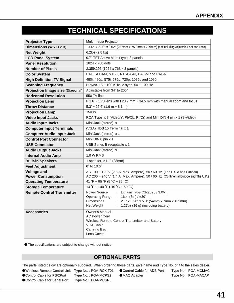
TECHNICAL SPECIFICATIONS
0.7" TFT Active Matrix type, 3 panels
Multi-media Projector
6.2lbs (2.8 kg)
10.12" x 2.98" x 9.02" (257mm x 75.8mm x 229mm) (not including Adjustble Feet and Lens)
1024 x 768 dots
2,359,296 (1024 x 768 x 3 panels)
PAL, SECAM, NTSC, NTSC4.43, PAL-M and PAL-N
H-sync. 15 ~ 100 KHz, V-sync. 50 ~ 100 Hz
Adjustable from 34” to 200”
550 TV lines
1 speaker, ø1.1" (28mm)
41 ˚F ~ 95 ˚F (5 ˚C ~ 35 ˚C)
14 ˚F ~ 140 ˚F (-10 ˚C ~ 60 ˚C)
Owner’s ManualAC Power CordWireless Remote Control Transmitter and BatteryVGA CableCarrying BagLens Cover
Projector Type
Net WeightDimensions (W x H x D)
Panel ResolutionNumber of PixelsColor System
Scanning FrequencyProjection Image size (Diagonal)
Horizontal Resolution
Built-in Speakers
Operating TemperatureStorage Temperature
Accessories
LCD Panel System
● The specifications are subject to change without notice.
F 1.6 ~ 1.78 lens with f 28.7 mm ~ 34.5 mm with manual zoom and focus
5.3’ ~ 26.6’ (1.6 m ~ 8.1 m)
150 W
RCA Type x 3 (Video/Y, Pb/Cb, Pr/Cr) and Mini DIN 4 pin x 1 (S-Video)
Projection LensThrow DistanceProjection LampVideo Input Jacks
Mini Jack (stereo) x 1Audio Input Jacks(VGA) HDB 15 Terminal x 1
Mini Jack (stereo) x 1
Mini DIN 8 pin x 1
Mini Jack (stereo) x 1
1.0 W RMS
Computer Input TerminalsComputer Audio Input JackControl Port Connector
Audio Output JacksInternal Audio Amp
0˚ to 10.6˚Feet Adjustment
Power Source : Lithium Type (CR2025 / 3.0V)Operating Range : 16.4’ (5m) / ±30˚Dimensions : 2.1” x 0.28” x 5.3” (54mm x 7mm x 135mm)Net Weight : 1.27oz (36 g) (including battery)
Remote Control Transmitter
480i, 480p, 575i, 575p, 720p, 1035i, and 1080iHigh Definition TV Signal
USB Series B receptacle x 1USB Connector
AC 100 ~ 120 V (2.8 A Max. Ampere), 50 / 60 Hz (The U.S.A and Canada)AC 200 ~ 240 V (1.4 A Max. Ampere), 50 / 60 Hz (Continental Europe and The U.K.)
Voltage and Power Consumption
OPTIONAL PARTSThe parts listed below are optionally supplied. When ordering those parts, give name and Type No. of it to the sales dealer.
● Wireless Remote Control Unit Type No. : POA-RCKIT01● Control Cable for PS/2Port Type No. : POA-MCPS2● Control Cable for Serial Port Type No.: POA-MCSRL
● Control Cable for ADB Port Type No.: POA-MCMAC● MAC Adapter Type No.: POA-MACAP
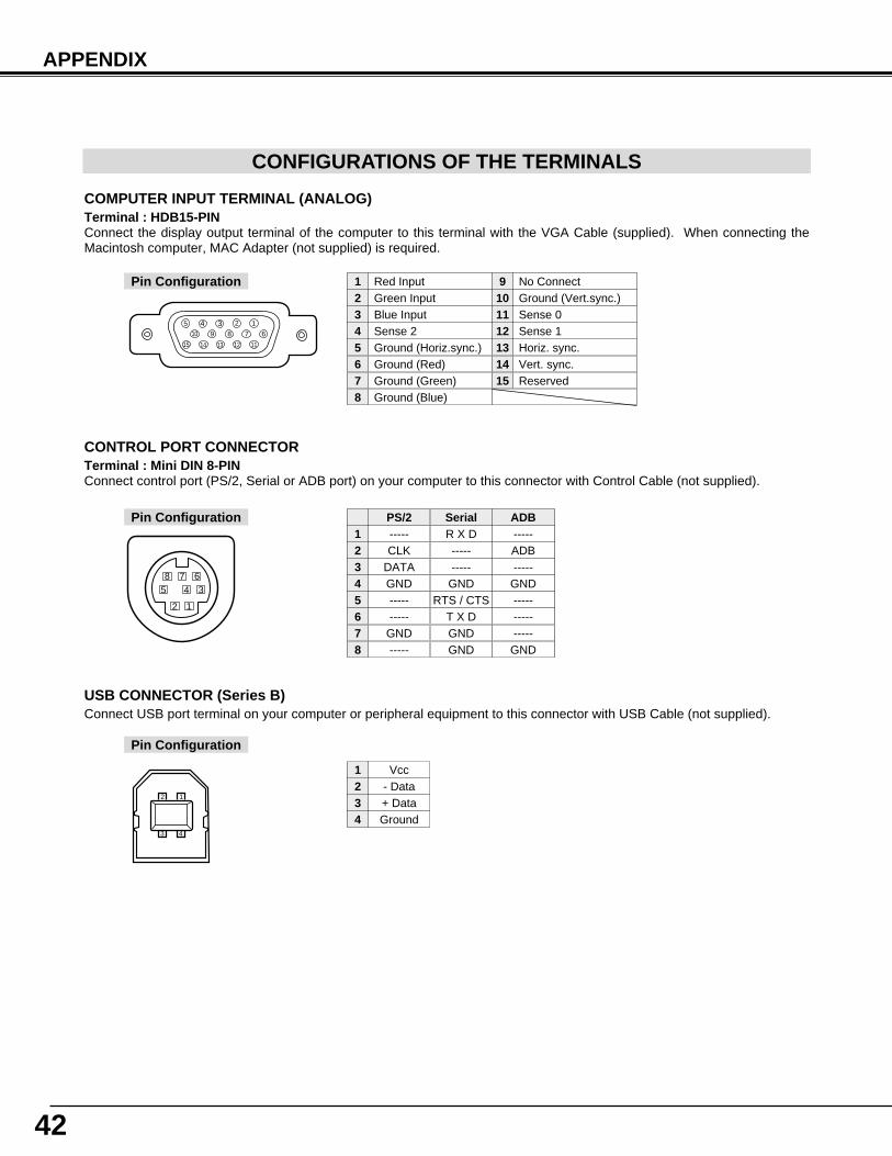
42
APPENDIX
CONFIGURATIONS OF THE TERMINALS
COMPUTER INPUT TERMINAL (ANALOG)Terminal : HDB15-PIN Connect the display output terminal of the computer to this terminal with the VGA Cable (supplied). When connecting theMacintosh computer, MAC Adapter (not supplied) is required.
5 123410 9 678
15 14 13 1112
Red Input
Ground (Horiz.sync.)
Green Input
Sense 2Blue Input
Ground (Red)Ground (Green)Ground (Blue)
1
5
2
43
678
No Connect
Horiz. sync.
Ground (Vert.sync.)
Sense 1Sense 0
Vert. sync.Reserved
9
13
10
1211
1415
Pin Configuration
Terminal : Mini DIN 8-PINConnect control port (PS/2, Serial or ADB port) on your computer to this connector with Control Cable (not supplied).
12
3458 7 6
Pin Configuration
CONTROL PORT CONNECTOR
-----CLK
DATAGND----------
GND-----
R X D----------
GNDRTS / CTS
T X DGNDGND
-----ADB-----
GND---------------
GND
PS/2 Serial ADB12345678
Vcc- Data+ DataGround
1234
USB CONNECTOR (Series B)
Pin Configuration
Connect USB port terminal on your computer or peripheral equipment to this connector with USB Cable (not supplied).
2
3 4
1

43

SANYO Electric Co., Ltd
Printed in JapanPart No. 610 294 2811 (1AA6P1P2903-- MW6A)