Embed Size (px)
Citation preview

TECH NOTE: PLC TO IN-SIGHT COMMUNICATIONS USING EIP


PLC to In-Sight Communications Using EIP
Copyright, Trademarks, Patents The software described in this document is furnished under license, and may be used or copied only in accordance with the terms of such license and with the inclusion of the copyright notice shown on this page. The software, this document, nor any copies thereof may be provided to or otherwise made available to anyone other than the licensee. Title to and ownership of this software remains with Cognex Corporation or its licensor. Cognex Corporation assumes no responsibility for the use or reliability of its software on equipment that is not supplied by Cognex Corporation. Cognex Corporation makes no warranties, either express or implied, regarding the described software, its merchantability or its fitness for any particular purpose.
The information in this document is subject to change without notice and should not be construed as a commitment by Cognex Corporation. Cognex Corporation is not responsible for any errors that may be present in either this document or the associated software.
This document may not be copied in whole or in part, nor transferred to any other media or language, without the written permission of Cognex Corporation.
Tech Note: In-Sight to PLC Communications Using EIP Revision 3 June 2006 Copyright © 2003-2005 Cognex Corporation. All Rights Reserved.
The hardware and portions of the software described in this document may be covered by one or more of the following U.S. patents (other U.S. and foreign patents are pending):
Hardware 4,972,359; 5,526,050; 5,657,403; 5,793,899
Vision Tools 5,495,537; 5,548,326; 5,583,954; 5,602,937; 5,640,200; 5,717,785; 5,742,037; 5,751,853; 5,768,443; 5,796,868; 5,818,443; 5,825,483; 5,825,913; 5,845,007; 5,859,466; 5,872,870; 5,909,504
The following are registered trademarks of Cognex Corporation:
Cognex Cognex, Vision for Industry In-Sight "crosshair" logo In-Sight
The following are trademarks of Cognex Corporation:
The Cognex logo VAN (Vision Area Network)
Other product and company names mentioned herein are the trademarks, or registered trademarks, of their respective owners.
1
PLC to In-Sight Communications Using EIP
Table of Contents 1 Introduction ......................................................................................................................... 3
1.1 Purpose ................................................................................................................... 3
1.2 Scope....................................................................................................................... 3
1.3 EtherNet Industrial Protocol (EIP) ........................................................................... 3
1.3.1 Map Specification (MapSpec)....................................................................... 4
1.3.2 Change of State Function............................................................................. 7
1.3.3 PCCC (PC3) and Implicit Messaging Formats.............................................. 9
1.3.4 Explicit Messaging Formats........................................................................ 10
2 Explicit Messaging Example ............................................................................................. 13
2.1 Configuration ......................................................................................................... 13
2.1.1 Components Needed.................................................................................. 13
2.1.2 Summary of Steps ...................................................................................... 13
3 Implicit Messaging Example ............................................................................................. 19
3.1 Configuration ......................................................................................................... 19
3.1.1 Components Needed.................................................................................. 19
3.1.2 Setting up in RSLogix 5000 ........................................................................ 19
4 PCCC (PC3) Communications Example ........................................................................... 23
4.1 Configuration ......................................................................................................... 23
4.1.1 Components Needed.................................................................................. 23
4.1.2 Using RSLogix 500..................................................................................... 23
4.1.3 Message (MSG) Instruction........................................................................ 24
4.1.4 Setup Screen for the MSG Instruction........................................................ 25
4.2 Using the MSG Instruction to Receive Data.......................................................... 27
4.3 Sending Native Mode Commands from an SLC5/05 ............................................ 28
4.4 Message Instruction results................................................................................... 30
2

PLC to In-Sight Communications Using EIP
1 Introduction
1.1 Purpose The purpose of this document is to aid in the configuration of various Programmable Logic Controllers (PLCs) to communicate with In-Sight systems using the EtherNet Industrial Protocol (EIP). Users should already be familiar with the specific hardware and software configuration tasks pertinent to their system.
1.2 Scope The scope of this document is to enable an operator familiar with the EIP protocol and the applicable PLC equipment and software to successfully communicate with In-Sight® systems. This document also provides examples of tested communication configurations.
This document is organized in four sections:
Introduction – This section introduces the concepts of the Ethernet Industrial Protocol and it’s application to In-Sight systems.
Explicit Messaging Example – This section provides an example of PLC communications with the In-Sight system using explicit messaging.
Implicit Messaging Example – This section provides an example of PLC communications with the In-Sight system using implicit messaging.
PCCC (PC3) Communications Example - This section provides an example of PC3 communications with the In-Sight system using explicit messaging and the SLC5/05.
1.3 EtherNet Industrial Protocol (EIP) The EtherNet Industrial Protocol incorporates the TCP and UDP layers of the Ethernet protocol in the transmission of data.
Because TCP/IP is point-to-point, EIP uses this layer for explicit messaging only. Explicit messaging is described as those messages in which the data field carries both protocol information and instructions for service performance. With explicit messaging, nodes must interpret each message, execute the requested task and generate responses. These types of messages can be used for device and job configuration, setup, etc.
Explicit messaging uses one of two packet types: Generic CIP (Control/Information Protocol) or PCCC (PC3).
The UDP/IP protocol, which can multicast, is used for implicit messaging. With implicit messaging, the data field contains no protocol information, only real-time I/O data. The meaning of the data is predefined at the time the connection is established and processing time in the node is therefore minimized during runtime. Such messages are low overhead, short and provide the required time-critical performance needed for control.
In-Sight systems support explicit or implicit messages from a single I/O client at any given time. An I/O client is described as the PLC device communicating with the host In-Sight system.
3

PLC to In-Sight Communications Using EIP
The protocol matrix for Rockwell’s Allen-Bradley PLCs is shown in Table 1-1.
Table 1-1:EIP Protocol Matrix
HARDWARE SOFTWARE EIP PROTOCOL
PLC5 RSLogix 5 PC3
SLC RSLogix 500 PC3
ControlLogix RSLogix 5000 Implicit Explicit (Generic CIP, PC3)
NOTE Every In-Sight sensor has a factory-assigned unique Media Access Control (MAC) address assigned to it, which cannot be changed or deleted. The MAC address is a hardware address that identifies a specific node of a network. The MAC address is made up of 6 bytes: 00-d0-24-xx-xx-xx. The first three bytes of the MAC address are the same for all In-Sight sensors: 00-d0-24. The last 3 bytes of the MAC address are unique to each sensor, represented as “xx-xx-xx”. When sending the MAC address over Ethernet/IP, In-Sight reverses the last three bytes of the MAC address and an “f4” byte value is displayed as the last byte. For example, the MAC address 00-d0-24-01-02-03 is sent over Ethernet/IP as 0x030201f4.
1.3.1 Map Specification (MapSpec) The map specification (MapSpec) provides the method of accessing or writing data to the applicable assembly object. The assembly object describes the communication services available and a common means by which information is exchanged between the Client (PLC) and the Server (In-Sight). The Input and Output assembly objects are configured as shown in Table 1-2 and Table 1-3.
Table 1-2: Input Assembly Object
3 2 1 0
Cmd Reserved 0
12 0
1234.57 4
8
12
16
1234 20
123 24
28
Cognex Corp 32
…
132
Input Assembly:
Class 0x04
Instance 0x01
Size 132 bytes (33 32-bit words)
Data Configuration:
Bytes 0-2 (3 bytes) - Reserved for future use
Byte 3 (1 byte) – Command byte
Bytes 4-132 (128-bytes) - Spreadsheet data (user definable via MapSpec).
4

PLC to In-Sight Communications Using EIP
Table 1-3: Output Assembly Object
3 2 1 0
Reserved 0
12 0
1234.57 4
8
12
16
1234 20
123 24
28
Cognex Corp 32
…
132
Output Assembly:
Class 0x04
Instance 0x02
Size 132-bytes (33 32-bit words)
Data Configuration:
Bytes 0-3 (4 bytes) – Reserved for future use
Bytes 4-132 (128-bytes) Spreadsheet data (user definable via MapSpec)
The relationship between the Input and Output Assembly is reversed between the Client (the PLC) and the Server (the In-Sight system). For example, the Client’s Output Assembly outputs data to the Server Input Assembly as shown in Table 1-4.
Table 1-4: I/O Assembly Relationship
CLIENT MESSAGE CLIENT ASSEMBLY IN-SIGHT FUNCTION IN-SIGHT ASSEMBLY
Write Input Assembly WriteEIP Output Assembly
Read Output Assembly ReadEIP Input Assembly
The input to the assembly object is specified in the MapSpec, which consists of a list of specifiers delimited by colon (:) characters. Each specifier has two parts: the byte offset, and a data type code. The data type codes are listed in Table 1-5.
Table 1-5: MapSpec Data Type Codes
DATA TYPE CODE BYTE LENGTH ROCKWELL EQUIVALENT
i or I 1 Byte SINT
il or IL 2 Bytes INT
d or D 4 Bytes DINT (ControlLogix only)
f or F 4 Bytes REAL
s or S 1 to 128 Bytes* Array of SINTs
* Each byte after the start byte of the string will be interpreted as a character until a null (\00) byte is encountered or until another data type is specified (e.g., ‘8s:13i’ means that starting at byte 8, all bytes until 13 will be interpreted as characters for a total of five characters).
5

PLC to In-Sight Communications Using EIP
The MapSpec tells the applicable In-Sight functions how to encode or decode the data that exists in the assembly object. A colon (:) separates each data element. In Figure 1-1, the value of the Mapping parameter for the ReadEIP function, “0f:4f:8f”, has 3 elements: 0f, 4f, 8f. The first element indicates that starting at data byte 0 of the Input Assembly; translate the data into a float (0f → first byte, type float). Since a float is 4 bytes long, the next piece of data starts at the fourth byte and is also a float (4f → fourth byte, type float). The last piece of data starts at the eighth byte and is also a float (8f → eighth byte, type float).
The value of the Mapping parameter for the WriteEIP function, “0il:2il:4il”, also has 3 elements: 0il, 2il, 4il. The first element indicates that starting at data byte 0 of the Input Assembly, translate the data into an integer (0il → zero byte, type integer). Since an integer is 2 bytes long, the next piece of data starts at the second byte and is also an integer (2il → second byte, type integer). The last piece of data starts at the fourth byte and is also an integer (4il → fourth byte, type integer).
Figure 1-1: MapSpec Examples in ReadEIP and WriteEIP Functions
NOTE The maximum length for input data is 128-bytes.
When using the ReadEIP function, a corresponding GetEIPData function is required. GetEIPData has two parameters: ReadEIP structure (points to a ReadEIP function on the spreadsheet), and an Index (which tells it what element of the MapSpec to get data from). For example: GetEIPData (A2, 1) gets the 2nd element (In-Sight uses a 0 index as the first element) from the ReadEIP function in cell A2 (Figure 1-1).
6
PLC to In-Sight Communications Using EIP
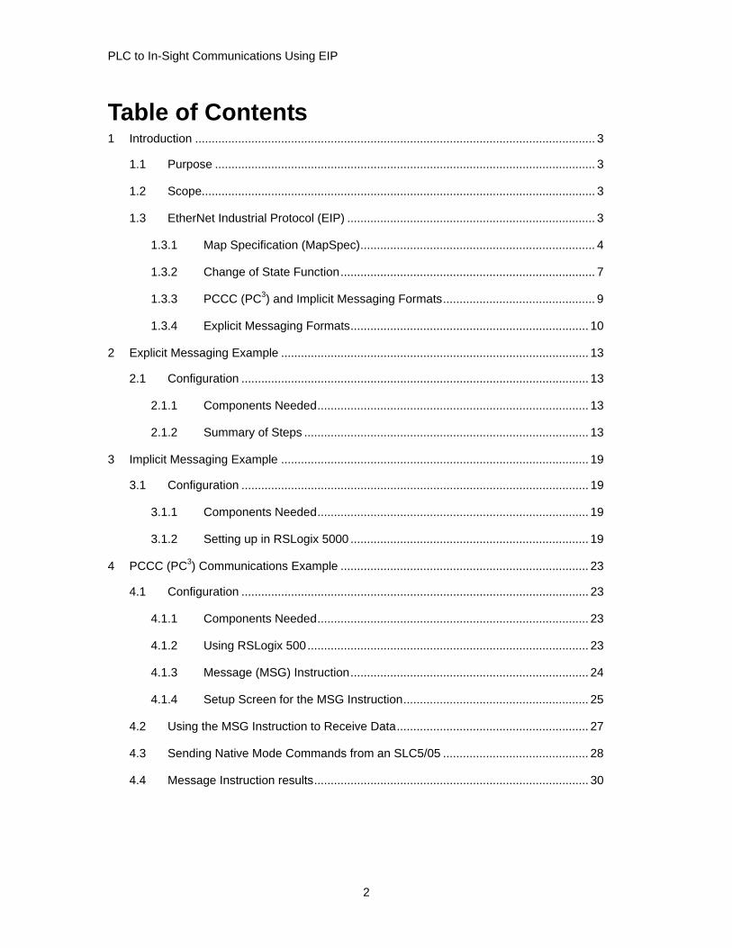
1.3.2 Change of State Function (In-Sight software version 2.43 and higher)
To provide an additional level of acquisition control using EtherNet/IP, a change of state (COS) field has been added to the assembly object.
Table 1-6 and Table 1-7 show the changes to the assembly object with the implementation of this function.
Table 1-6: In-Sight Input Assembly (Prior to V2.43)
3 2 1 0
0 CMD Reserved
1 1 C L P
2 97 123 42 \0
3 3.14159
4 0 2589 0
…
132
Table 1-7: In-Sight Input Assembly (After V2.43)
3 2 1 0
0 CMD COS Reserved
1 1 C L P
2 97 123 42 \0
3 3.14159
4 0 2589 0
…
132
CMD – is still the command byte with 1 new acceptable data value:
99 (0x63) – to trigger on every packet (continuous trigger). This method is not recommended since it will attempt to trigger acquisitions at the RPI rate. It appears here only for backward compatibility with jobs developed older firmware.
100 (0x64) – to trigger only when the COS value has changed state
COS – Change of State value
7
PLC to In-Sight Communications Using EIP
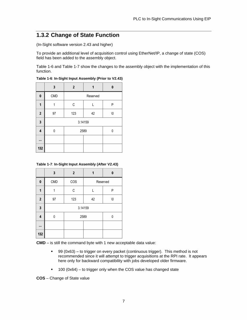
In-Sight will trigger whenever it sees the COS byte’s value change from its previous value to a different non-zero value. In-Sight will not trigger when the COS byte’s value changes to 0.
EXAMPLE: If the COS byte is 0, the system will trigger when the COS byte is incremented from 0 to 1. The system will trigger again, each time the COS byte’s value is changed to a different non-zero value such as when continuing to increment the COS byte.
Reserved – Reserved bytes. No data to be placed here.
The data portion of the assembly object (bytes 4 – 132) remains the same. For both methods of network triggering, the null terminated “Master Name” string (for example: “PLC1\0”) has to appear in the first part of the data section. In the AcquireImage property sheet (cell A0), the Trigger parameter must be set to Network, and the Master Name Parameter must contain the same string that will appear in the first bytes of the data portion of the packet (“PLC1”).
NOTES: ■ If the Master Name Parameter is left blank, the string at the beginning of the assembly object is not
required.
■ Regardless of the state of the CMD and COS bytes, the PLC may still send and receive data to/from the In-Sight server. The CMD byte only affects the AcquireImage event.
Change of State Functionality
Assume the following initial setup from the Client:
3 2 1 0
0 100 0 Reserved
1 1 C L P
2 97 123 42 \0
3 3.14159
4 0 2589 0
…
132
Initially In-Sight receives a COS byte with a value of 0, so regardless of the previous value of the COS byte, In-Sight will not trigger. The client then begins to send packets at the Request Packet Interval (RPI) and the server (In-Sight) receives them. The camera will not be triggered at this point because the COS byte has not changed (initial state was 0 and has remained 0). At some point later, the client wants to tell In-Sight to trigger, so it changes the COS byte to 1. That packet is sent out and received by In-Sight. In-Sight determines that the COS byte has changed from 0 to 1 and will fire an acquisition event. If, on the next cycle, the client does not change the COS byte, the camera will not acquire (client continues to send 1). If the client wants to trigger again, the COS byte must be set to a different non-zero value. In-Sight will receive that packet, determine that the COS byte has been changed from 1 to a different non-zero value and fire a second acquisition event.
8
PLC to In-Sight Communications Using EIP
To prevent the In-Sight from missing triggers, it is recommended that the COS byte be incremented rather than simply toggled between two non-zero values. To understand this problem, consider toggling the COS byte between 1 and 2 with the PLC’s RPI set to 300 msec. If the PLC’s logic updated the COS byte every 100 msec, with a sequence of changes such as 1->2->1->2, In-Sight would sometimes miss the value changing from 1 to 2. Instead In-Sight would see 1->1->2 and therefore miss a trigger.
1.3.3 PCCC (PC3) and Implicit Messaging Formats PC3 and Implicit messaging protocols also employ the In-Sight’s ReadEIP and WriteEIP functions. PC3 may also use a limited Native Mode command set to access and write data to/from the In-Sight system. The ReadEIP and WriteEIP functions require the following inputs:
Event
MapSpec
The Event input specifies the update event on which to read data. This argument must reference cell A0 (the AcquireImage function), or a cell containing a soft event.
NOTE Currently, only the AcquireImage event is supported with implicit messaging via the CMD byte. PC3 cannot use the CMD byte.
The Native Mode commands provide access to the In-Sight spreadsheet. Generally, no additional functions are needed in the spreadsheet to support Native Mode. A client (the PLC) issues a command (such as load file) and the server (In-Sight) will attempt to execute the command and return a status.
Table 1-8 lists the Native Mode commands supported by PC3 and Implicit messaging formats.
Native Mode commands are issued as strings to In-Sight. For more information on formulating Native Mode commands refer to the In-Sight Guide and Reference.
9

PLC to In-Sight Communications Using EIP
Table 1-8: Supported Native Mode Commands
COMMAND NAME COMMAND PARAMETERS EXAMPLE
Delete File** DF <filename>.JOB DFTESTFILE.JOB
Set Event* SE Soft Event 0-7 Acquire Event 8
SE2
Set Online* SO 0 – Set Offline 1 – Set Online
SO1
Store File** TF <filename>.JOB TFTESTFILE.JOB
Load File** LF <filename>.JOB LFTESTFILE.JOB
* Must be manually set ONLINE for Native Mode command to work ** Must be set OFFLINE for Native Mode command to work
All Native Mode commands operate the same across Telnet or Serial connections.
Refer to the command definitions for input parameter specifications.
Carriage returns (0x0D) or line feeds (0x0A) are not required for any command sent from the PLC and will be ignored.
Native Mode Commands other than those listed above may function correctly; however, they are not supported and are used at your own risk.
1.3.4 Explicit Messaging Formats Explicit messaging protocols employ In-Sight’s Native Mode commands to access and send data to the In-Sight system. Extended Native Mode commands are not supported at this time.
NOTES: ■ The In-Sight 3000 does not support Native Mode commands using PC3 Explicit Messaging.
■ Native Mode commands can be separated into 4 distinct groups by command format.
Native Mode Commands by Group
Every command returns at least a status byte. So, for every Explicit Message configuration, the destination must be at least a DINT (4 byte integer).
Type 1 (Command only)
Type 2 (Command and one parameter)
Type 3 (Command, column, and row)
Type 4 (Command, column, row, and data)
10

PLC to In-Sight Communications Using EIP
Table 1-9: Type 1 Commands
COMMAND MEMBER TYPE STYLE DESCRIPTION
Get File GF Get Online GO
Command SINT[2] ASCII 2 characters making the command (e.g. GO for Get Online)
Table 1-10: Type 2 Commands
COMMAND MEMBER TYPE STYLE DESCRIPTION
Command SINT[2] ASCII 2 characters making the command (e.g. SO for Set Online)
Delete File DF[filename] Load File LF[filename Set Event SE[int] Set Job SJ[id] Set Online SO[int] Store File TF[filename]
Data SINT (make an array if commands takes more than 1 byte)
HEX Data that follows command (e.g. if command is SO then data is 1 or 0)
Table 1-11: Type 3 Commands
COMMAND MEMBER TYPE STYLE DESCRIPTION
Command SINT[2] ASCII 2 characters making the command (e.g. GV for Get Value)
Column SINT ASCII 1 byte for column A-Z
Get Value GV[column][row]
Row INT HEX Number 0 - 399 for the row
Table 1-12: Type 4 Commands
COMMAND MEMBER TYPE STYLE DESCRIPTION
Command SINT[2] ASCII 2 characters making the command (e.g. SF for Set Float)
Column SINT ASCII 1 byte for column A-Z
Row INT HEX Number 0 - 399 for the row
Set Float SF[column][row][float] Set Integer SI[column][row][int] Set String SS[column][row][string]
Data INT (for SI) REAL (for SF) SINT (for SS)
11

PLC to In-Sight Communications Using EIP
12

PLC to In-Sight Communications Using EIP
2 Explicit Messaging Example
2.1 Configuration This section outlines an Explicit Communications configuration between the In-Sight system and the PLC. This example uses the ControlLogix Controller and Rockwell’s RSLogix 5000 software.
2.1.1 Components Needed In-Sight system with Firmware version 2.30.08 or higher.
ControlLogix Controller (1756-A4 in a 4-slot rack).
1756-ENET /B Ethernet gateway module.
Rockwell’s RSLogix 5000 programming software (version 8.0 or higher).
NOTE This section does not apply to In-Sight software version 2.21 or previous versions.
2.1.2 Summary of Steps Create user-defined data types to send and receive Native Mode commands (these
are similar to C structures).
Create tags based on these user-defined data types and fill them in with a Native Mode command.
Create a Message Instruction (MSG) to send this data.
Because Native Mode commands are to be sent, there is no additional programming on the In-Sight spreadsheet other than what is normally done to create an In-Sight Job. The In-Sight system treats these messages the same as receiving a Native Mode command from a Telnet session. Step 1: Create a New Project:
1. Open RSLogix 5000.
2. Create a new Project (File New).
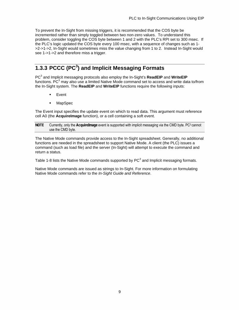
Step 2: Create User-Defined types:
1. Right click on the User-Defined folder and select New Type.
13
PLC to In-Sight Communications Using EIP
Figure 2-1: New Project showing User-Defined Folder
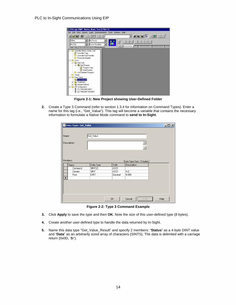
2. Create a Type 3 Command (refer to section 1.3.4 for information on Command Types). Enter a name for this tag (i.e., “Get_Value”). This tag will become a variable that contains the necessary information to formulate a Native Mode command to send to In-Sight.
Figure 2-2: Type 3 Command Example
3. Click Apply to save the type and then OK. Note the size of this user-defined type (8 bytes).
4. Create another user-defined type to handle the data returned by In-Sight.
5. Name this data type “Get_Value_Result” and specify 2 members: “Status” as a 4-byte DINT value and “Data” as an arbitrarily sized array of characters (SINTS). The data is delimited with a carriage return (0x0D, ‘$r’).
14

PLC to In-Sight Communications Using EIP
Figure 2-3: Type 3 Command Example
6. Click Apply to save the type and then OK.
NOTE You can repeat this for each of the Command Types for sending different Native Mode commands to In-Sight (i.e., Set Event, Set Float, etc.).
Step 3: Create tags (variables) based on user-defined types:
1. From the left-hand panel, select Controller Tags, and then click the Edit Tags tab, to create a new tag.
2. Enter a name for this tag (i.e.”Get_Value_Command”), and then select the ellipse button (“…”) in the Type field to bring up the list of usable data types. Choose Get_Value (the user-defined data type we just created.) This tag will contain the Get Value Native Mode Command that is sent to In-Sight. Click OK.
Figure 2-4: Select Data Type Dialog
3. Create another tag called “GV_Result” and make it of type Get_Value_Result. This will be the tag that receives the return value from In-Sight. Click OK.
4. Click the Monitor Tags tab.
15
PLC to In-Sight Communications Using EIP
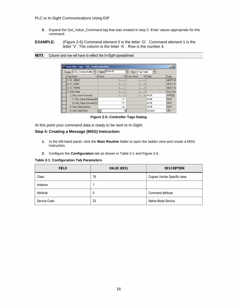
5. Expand the Get_Value_Command tag that was created in step 2. Enter values appropriate for this command.
EXAMPLE: (Figure 2-5) Command element 0 is the letter ‘G’. Command element 1 is the letter ‘V’. The column is the letter ‘A’. Row is the number 4.
NOTE Column and row will have to reflect the In-Sight spreadsheet.
Figure 2-5: Controller Tags Dialog
At this point your command data is ready to be sent to In-Sight. Step 4: Creating a Message (MSG) Instruction:
1. In the left-hand panel, click the Main Routine folder to open the ladder view and create a MSG instruction.
2. Configure the Configuration tab as shown in Table 2-1 and Figure 2-6.
Table 2-1: Configuration Tab Parameters
FIELD VALUE (HEX) DESCRIPTION
Class 78 Cognex Vendor Specific class
Instance 1
Attribute 0 Command attribute
Service Code 33 Native Mode Service
16

PLC to In-Sight Communications Using EIP
Figure 2-6: Message Configuration (Configuration Tab) Dialog
3. Set the Source Element to point to the Command element of the Get_Value_Command tag.
4. Set the Source Length to 12. This is the number of bytes the structure will use. This can be found in the Properties of the user-defined type.
5. Set the Destination to the GV_Result tag.
6. In the Communication tab, set the path to the In-Sight unit. The format is "Source IP, Medium (Ethernet = 2), Destination IP". For example (refer to Figure 2-7), ENET_B_MODULE is the module in the rack (selected by using the Browse button). The number 2 indicates “Use Ethernet Communication”; 10.123.1.11 is the IP address of the In-Sight unit.
Figure 2-7: Message Configuration (Communication Tab) Dialog
7. Click OK.
8. Download your program to the controller.
9. Configure the In-Sight spreadsheet with data (A4 in this example).
10. Trigger the message instruction using the method that is appropriate for the application.
17

PLC to In-Sight Communications Using EIP
NOTE This may require additional instructions in your logic program.
Figure 2-8: Example: Message Trigger Message Instruction
11. When the done (DN) bit is enabled, the message has completed. You can then examine the result data in the Controller Tags (see Figure 2-9).
Figure 2-9: Control Tags dialog
12. For this example the result status is 1, indicating that the Native Mode command succeeded on the In-Sight system. In the result data we see the result value of “2.000” as a string with header and trailer of “$r”. The next step is to convert that string into a Real that the ControlLogix can use. Refer to the Rockwell documentation for more information and proper user of (MOV, COP, and STOR) instructions.
Figure 2-10: Convert from String to REAL Using STOR Example
18

PLC to In-Sight Communications Using EIP
3 Implicit Messaging Example
3.1 Configuration This section outlines an Implicit Messaging configuration between the In-Sight system and the PLC. This example uses the ControlLogix 5550 Controller and Rockwell’s RSLogix 5000 software.
3.1.1 Components Needed In-Sight Firmware (version 2.30.08 or higher)
Rockwell’s RSLogix 5000 programming software (version 8.0 or higher)
Allen-Bradley ControlLogix controller with corresponding firmware to support RSLogix5000 v8.0.
3.1.2 Setting up in RSLogix 5000 1. Open RSLogix 5000 .
2. Create a new project (File New).
3. In the left-hand pane, right click on the I/O Configuration folder and select New Module.
4. Select the current Allen-Bradley Ethernet module that is in the rack (e.g. 1756-ENET /B) and click OK.
5. Enter a name, slot, and IP address/host name for the module and click FINISH.
6. In the left-hand pane, right-click on the Ethernet module you just added and select NEW MODULE.
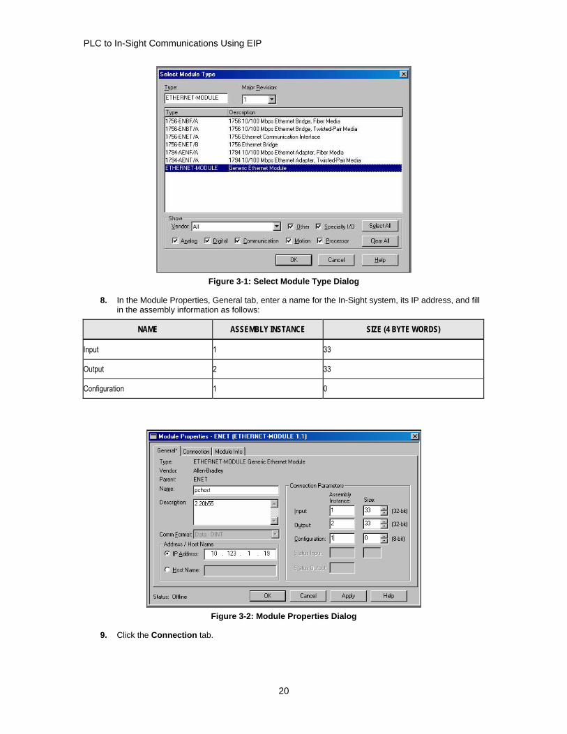
7. Select the ETHERNET-MODULE: Generic Ethernet Module type and click OK. This will be your connection to the In-Sight system.
19
PLC to In-Sight Communications Using EIP
Figure 3-1: Select Module Type Dialog
8. In the Module Properties, General tab, enter a name for the In-Sight system, its IP address, and fill in the assembly information as follows:
NAME ASSEMBLY INSTANCE SIZE (4 BYTE WORDS)
Input 1 33
Output 2 33
Configuration 1 0
Figure 3-2: Module Properties Dialog
9. Click the Connection tab.
20

PLC to In-Sight Communications Using EIP
10. Enter an appropriate Request Packet Interval (RPI). This should be long enough to allow for all your vision processing to complete. Click FINISH.
Figure 3-3: Module Properties Dialog – RPI Input Box
21

PLC to In-Sight Communications Using EIP
22
PLC to In-Sight Communications Using EIP
4 PCCC (PC3) Communications Example
4.1 Configuration This section outlines a PCCC (PC3) Communications configuration between the In-Sight system and the PLC. This example uses the Allen-Bradley SLC5/05 and Rockwell’s RSLogix 500 software.
4.1.1 Components Needed In-Sight Firmware (version 2.2 or higher)
Rockwell’s RSLogix 500 programming software (version 4.5 or higher)
Allen-Bradley SLC5/05 controller with corresponding firmware to support RSLogix500
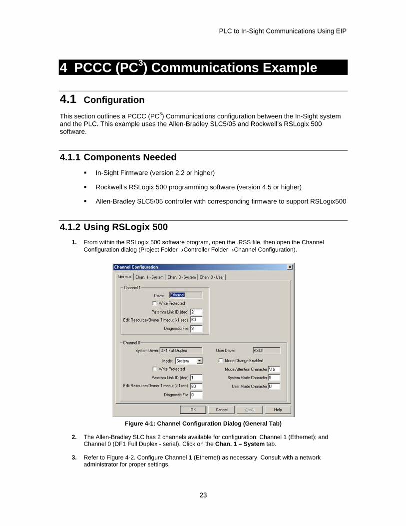
4.1.2 Using RSLogix 500 1. From within the RSLogix 500 software program, open the .RSS file, then open the Channel
Configuration dialog (Project Folder→Controller Folder→Channel Configuration).
Figure 4-1: Channel Configuration Dialog (General Tab)
2. The Allen-Bradley SLC has 2 channels available for configuration: Channel 1 (Ethernet); and Channel 0 (DF1 Full Duplex - serial). Click on the Chan. 1 – System tab.
3. Refer to Figure 4-2. Configure Channel 1 (Ethernet) as necessary. Consult with a network administrator for proper settings.
23

PLC to In-Sight Communications Using EIP
NOTE Verify that the IP/Subnet/Gateway parameters are correct on the PLC and the In-Sight unit.
Figure 4-2: Channel Configuration Dialog (Channel 1 – System Tab)
4. Configure the Timeouts as required.
NOTE The connection timeout and reply timeout are in milliseconds, inactivity is in seconds. These parameters will determine the Message Timeout parameter later used by the system when sending and receiving requests. (Msg Connection Timeout + Msg Reply Timeout + 5mS = Msg Timeout)
4.1.3 Message (MSG) Instruction Message instructions may now be constructed within the application. Refer to the RSLogix 500 documentation for expanded instructions for developing messages.
The following setup parameters can be configured within a Message (MSG) Instruction.
Figure 4-3: MSG Instruction
Type: Peer-To-Peer. This cannot be modified.
Read/Write: Select the function you want to perform on an In-Sight system. Read retrieves data from the In-Sight; write sends data to the In-Sight.
24
PLC to In-Sight Communications Using EIP
Target Device: Choose PLC5 to talk to an In-Sight system. This tells the SLC which communication protocol to use. The In-Sight system acts much like a ControlLogix controller. (See Rockwell document 13862.)
Local/Remote: Choose Local to indicate that the In-Sight system is on the same network as the SLC. Remote tells the SLC that you will be communicating to an In-Sight on another network. For remote communication, you must direct the message through another device acting as a gateway to that secondary network. Typically, this could be an Allen-Bradley ControlLogix controller. (Refer to Rockwell documentation on how to address devices on other networks through a gateway.)
Control Block: This is a temporary integer file that the MSG instruction uses to store data (i.e., IP address, message type, etc.). This is typically not the user data to be sent.
Control Block Length: This is automatically computed by the MSG instruction.
Setup Screen: Selecting Setup Screen will open the Message Instruction Setup dialog.
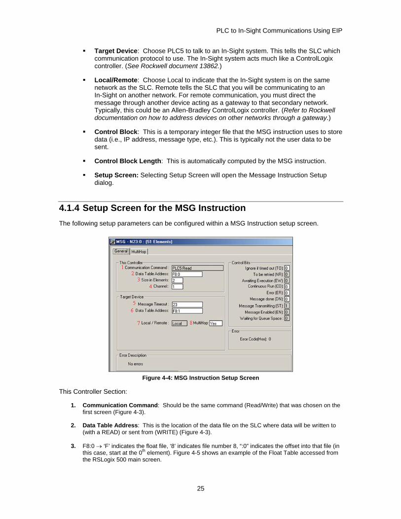
4.1.4 Setup Screen for the MSG Instruction The following setup parameters can be configured within a MSG Instruction setup screen.
Figure 4-4: MSG Instruction Setup Screen
This Controller Section:
1. Communication Command: Should be the same command (Read/Write) that was chosen on the first screen (Figure 4-3).
2. Data Table Address: This is the location of the data file on the SLC where data will be written to (with a READ) or sent from (WRITE) (Figure 4-3).
3. F8:0 → ‘F’ indicates the float file, ‘8’ indicates file number 8, “:0” indicates the offset into that file (in this case, start at the 0th element). Figure 4-5 shows an example of the Float Table accessed from the RSLogix 500 main screen.
25
PLC to In-Sight Communications Using EIP
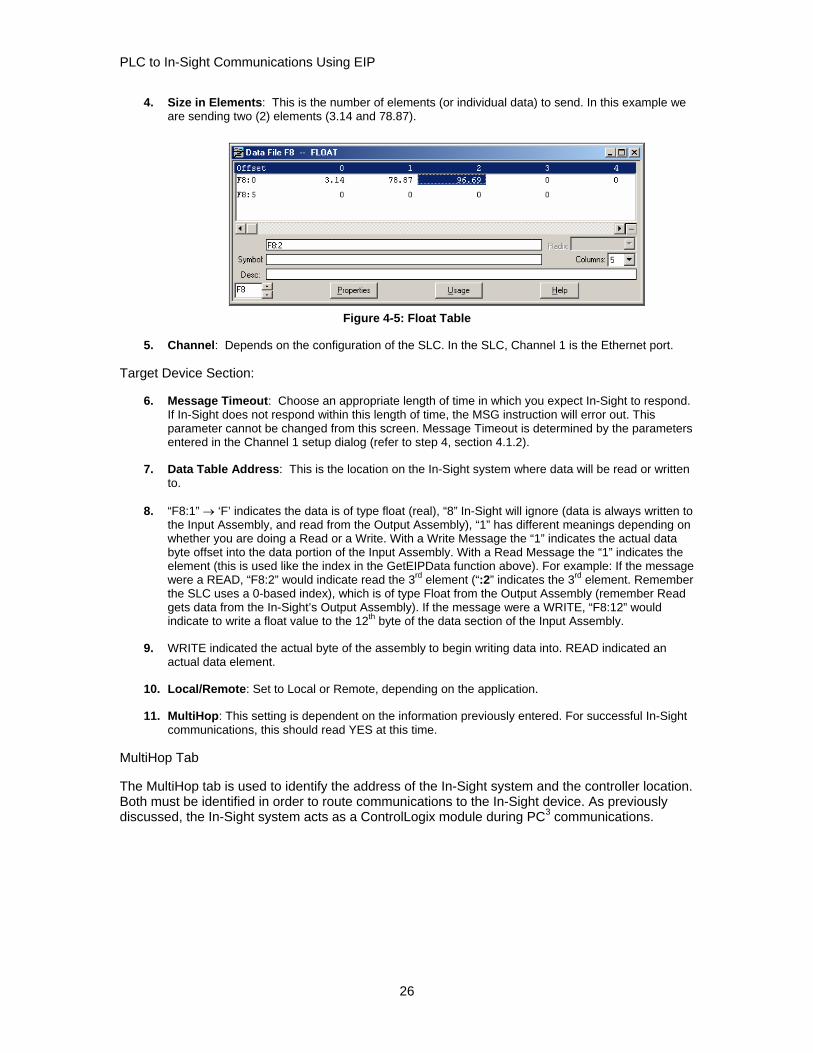
4. Size in Elements: This is the number of elements (or individual data) to send. In this example we are sending two (2) elements (3.14 and 78.87).
Figure 4-5: Float Table
5. Channel: Depends on the configuration of the SLC. In the SLC, Channel 1 is the Ethernet port.
Target Device Section:
6. Message Timeout: Choose an appropriate length of time in which you expect In-Sight to respond. If In-Sight does not respond within this length of time, the MSG instruction will error out. This parameter cannot be changed from this screen. Message Timeout is determined by the parameters entered in the Channel 1 setup dialog (refer to step 4, section 4.1.2).
7. Data Table Address: This is the location on the In-Sight system where data will be read or written to.
8. “F8:1” → ‘F’ indicates the data is of type float (real), “8” In-Sight will ignore (data is always written to the Input Assembly, and read from the Output Assembly), “1” has different meanings depending on whether you are doing a Read or a Write. With a Write Message the “1” indicates the actual data byte offset into the data portion of the Input Assembly. With a Read Message the “1” indicates the element (this is used like the index in the GetEIPData function above). For example: If the message were a READ, “F8:2” would indicate read the 3rd element (“:2” indicates the 3rd element. Remember the SLC uses a 0-based index), which is of type Float from the Output Assembly (remember Read gets data from the In-Sight’s Output Assembly). If the message were a WRITE, “F8:12” would indicate to write a float value to the 12th byte of the data section of the Input Assembly.
9. WRITE indicated the actual byte of the assembly to begin writing data into. READ indicated an actual data element.
10. Local/Remote: Set to Local or Remote, depending on the application.
11. MultiHop: This setting is dependent on the information previously entered. For successful In-Sight communications, this should read YES at this time.
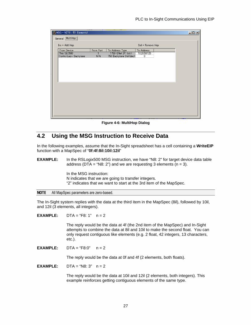
MultiHop Tab
The MultiHop tab is used to identify the address of the In-Sight system and the controller location. Both must be identified in order to route communications to the In-Sight device. As previously discussed, the In-Sight system acts as a ControlLogix module during PC3 communications.
26
PLC to In-Sight Communications Using EIP
Figure 4-6: MultiHop Dialog
4.2 Using the MSG Instruction to Receive Data In the following examples, assume that the In-Sight spreadsheet has a cell containing a WriteEIP function with a MapSpec of “0f:4f:8il:10il:12il”
EXAMPLE: In the RSLogix500 MSG instruction, we have “N8: 2” for target device data table address (DTA = “N8: 2”) and we are requesting 3 elements (n = 3). In the MSG instruction: N indicates that we are going to transfer integers. “2” indicates that we want to start at the 3rd item of the MapSpec.
NOTE All MapSpec parameters are zero-based.
The In-Sight system replies with the data at the third item in the MapSpec (8il), followed by 10il, and 12il (3 elements, all integers).
EXAMPLE: DTA = “F8: 1” n = 2 The reply would be the data at 4f (the 2nd item of the MapSpec) and In-Sight attempts to combine the data at 8il and 10il to make the second float. You can only request contiguous like elements (e.g. 2 float, 42 integers, 13 characters, etc.).
EXAMPLE: DTA = “F8:0” n = 2 The reply would be the data at 0f and 4f (2 elements, both floats).
EXAMPLE: DTA = “N8: 3” n = 2 The reply would be the data at 10il and 12il (2 elements, both integers). This example reinforces getting contiguous elements of the same type.
27

PLC to In-Sight Communications Using EIP
4.3 Sending Native Mode Commands from an SLC5/05
NOTE The In-Sight 3000 does not support Native Mode commands using PC3 Explicit Messaging.
1. Configure the SLC5/05 as necessary.
2. Create a String Table that will hold your Native Mode commands.
Figure 4-7: Create Data File Dialog
3. Add the required Native Mode command strings to the Data File
Figure 4-8: Data File String Table
4. Add a new Message (MSG) instruction to your ladder logic and configure it as shown in the following example:
28

PLC to In-Sight Communications Using EIP
Figure 4-9: Add and Configure a Message Instruction
5. Enter the MSG Setup Screen and configure it as follows:
Table 4-1: Configure MSG Setup Screen Parameters
THIS CONTROLLER (SLC) PARAMETER DESCRIPTION
Data Table Address: ST10:1 1st element from String Table (ST) created above
Size in Elements: 1 Always set to 1. PCCC MSG only allows for 1 string (therefore 1 command) to be sent at a time.
Channel: 1 Set this to the Ethernet Channel of your controller.
TARGET DEVICE (IN-SIGHT SYSTEM) PARAMETER DESCRIPTION
Message Timeout (From the Channel Configuration dialog)
Data Table Address: ST10:0 This is the destination address. For native mode commands this will always be ST10:0
Figure 4-10: Message Setup Dialog
29
PLC to In-Sight Communications Using EIP
6. Click the MultiHop tab and configure it as required:
EXAMPLE: In this example, only the IP address of the destination In-Sight system needed to be set.
7. When everything is configured, close the MSG window.
8. Save your ladder logic, download it to the controller, then go online, and set the controller in RUN mode.
9. Trigger the message to send it to the In-Sight system.
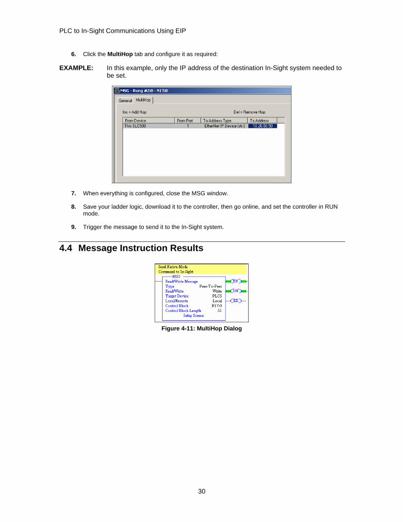
4.4 Message Instruction Results
Figure 4-11: MultiHop Dialog
30

PLC to In-Sight Communications Using EIP
The Enable (EN) bit of the message instruction will be set to 1 when the input to the instruction is set high. The Done (DN) bit will be set to 1 when In-Sight has replied that the Native Mode command was received and executed with success. If the Error bit (ER) bit is enabled (set to 1), there has been a problem with the message instruction. If an error occurs, click the Setup Screen for the MSG instruction. The Error Code will be shown at the bottom of the window. Error codes are listed in Table 4-2.
Table 4-2: Error Codes
ERROR CODE DESCRIPTION NATIVE MODE RETURN CODE
00 Success – No Error 1
10 Illegal Command or format 0
EE Command Cannot be executed -2, -4, or -5
D9 Reply not received before user-specified timeout. NA
F2 Invalid parameter or invalid data -1
31