Embed Size (px)
Citation preview

IM-P486-14 CH Issue 1 1
TEMPLATE
PLC Control Unit for CSM-PD Pre-heating and Degassing Systems
Installation, operation and Maintenance Manual
Printed in the UK © Copyright 2007
IM-P486-14CH Issue 1
3.635.5275.251

IM-P486-14 CH Issue 12
TEMPLATE

IM-P486-14 CH Issue 1 3
TEMPLATE
1 Safety information ..................................................................................................................4
2 General information ................................................................................................................ 8
3 Control unit ...........................................................................................................................10
4 Control features ....................................................................................................................12
5 External connections ............................................................................................................13
6 Main power supply ...............................................................................................................13
7 Display and keyboard ...........................................................................................................14
8 Manual mode ........................................................................................................................17
9 Automatic mode ...................................................................................................................22
10 Alarms and blocks ...............................................................................................................28
11 Confi guration ........................................................................................................................29
12 Repairs .................................................................................................................................. 32
Contents
IM-P486-14 CH Issue 14
TEMPLATE
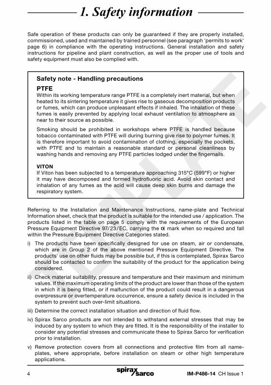
1. Safety informationSafe operation of these products can only be guaranteed if they are properly installed, commissioned, used and maintained by trained personnel (see paragraph 'permits to work' page 6) in compliance with the operating instructions. General installation and safety instructions for pipeline and plant construction, as well as the proper use of tools and safety equipment must also be complied with.
Safety note - Handling precautions
PTFEWithin its working temperature range PTFE is a completely inert material, but when heated to its sintering temperature it gives rise to gaseous decomposition products or fumes, which can produce unpleasant effects if inhaled. The inhalation of these fumes is easily prevented by applying local exhaust ventilation to atmosphere as near to their source as possible.
Smoking should be prohibited in workshops where PTFE is handled because tobacco contaminated with PTFE will during burning give rise to polymer fumes. It is therefore important to avoid contamination of clothing, especially the pockets, with PTFE and to maintain a reasonable standard or personal cleanliness by washing hands and removing any PTFE particles lodged under the fi ngernails.
VITONIf Viton has been subjected to a temperature approaching 315°C (599°F) or higher it may have decomposed and formed hydrofl uoric acid. Avoid skin contact and inhalation of any fumes as the acid will cause deep skin burns and damage the respiratory system.
Referring to the Installation and Maintenance Instructions, name-plate and Technical Information sheet, check that the product is suitable for the intended use / application. The products listed in the table on page 5 comply with the requirements of the European Pressure Equipment Directive 97/ 23 / EC, carrying the mark when so required and fall within the Pressure Equipment Directive Categories stated.
i) The products have been specifi cally designed for use on steam, air or condensate, which are in Group 2 of the above mentioned Pressure Equipment Directive. The products' use on other fl uids may be possible but, if this is contemplated, Spirax Sarco should be contacted to confi rm the suitability of the product for the application being considered.
ii) Check material suitability, pressure and temperature and their maximum and minimum values. If the maximum operating limits of the product are lower than those of the system in which it is being fi tted, or if malfunction of the product could result in a dangerous overpressure or overtemperature occurrence, ensure a safety device is included in the system to prevent such over-limit situations.
iii) Determine the correct installation situation and direction of fl uid fl ow.
iv) Spirax Sarco products are not intended to withstand external stresses that may be induced by any system to which they are fi tted. It is the responsibility of the installer to consider any potential stresses and communicate these to Spirax Sarco for verifi cation prior to installation.
v) Remove protection covers from all connections and protective fi lm from all name- plates, where appropriate, before installation on steam or other high temperature
applications.

IM-P486-14 CH Issue 1 5
TEMPLATE
Pressure Equipment Directive classificationThe category of the assembled unit is determined on the basis of the highest risk, resulting from the multiplication of volume (litres) by pressure (bar) or from the multiplication of DN (rated diameter) by design pressure.
Model Category
CSM-PD500 SEP
CSM-PD1000 SEP
CSM-PD2000 SEP
AccessEnsure safe access and if necessary a safe working platform (suitably guarded) before attempting to work on the product. Arrange suitable lifting gear if required.
LightingEnsure adequate lighting, particularly where detailed or intricate work is required.
Hazardous liquids or gases in the pipelineConsider what is in the pipeline or what may have been in the pipeline at some previous time. Consider: fl ammable materials, substances hazardous to health, extremes of temperature.
Hazardous environment around the productConsider: explosion risk areas, lack of oxygen (e.g. tanks, pits), dangerous gases, extremes of temperature, hot surfaces, fi re hazard (e.g. during welding), excessive noise, moving machinery.
The systemConsider the effect on the complete system of the work proposed. Will any proposed action (e.g. closing isolation valves, electrical isolation) put any other part of the system or any personnel at risk?
Dangers might include isolation of vents or protective devices or the rendering ineffective of controls or alarms. Ensure isolation valves are turned on and off in a gradual way to avoid system shocks.
Pressure systemsEnsure that any pressure is isolated and safely vented to atmospheric pressure. Consider double isolation (double block and bleed) and the locking or labelling of closed valves. Do not assume that the system has depressurised even when the pressure gauge indicates zero.

IM-P486-14 CH Issue 16
TEMPLATE
TemperatureAllow time for temperature to normalise after isolation to avoid the danger of burns and consider whether protective clothing (including safety glasses) is required.
PTFE seals - If seals made from PTFE have been subjected to a temperature approaching 260°C (500°F) or higher, they will give off toxic fumes, which if inhaled are likely to cause temporary discomfort. It is essential for a no smoking rule to be enforced in all areas where PTFE is stored, handled or processed as persons inhaling the fumes from burning tabacco contaminated with PTFE particles can develop 'polymer fume fever'.
VITON seals - If the Viton seat has been subjected to a temperature approaching 315°C (599°F) or higher it may have decomposed and formed hydrofl uoric acid. Avoid skin contact and inhalation of any fumes as the acid will cause deep skin burns and damage the respiratory system.
Tools and consumablesBefore starting work ensure that you have suitable tools and / or consumables available. Use only genuine Spirax Sarco replacement parts.
Protective clothingConsider whether you and / or others in the vicinity require any protective clothing to protect against the hazards of, for example, chemicals, high / low temperature, radiation, noise, falling objects, and dangers to eyes and face.
Permits to workAll work must be carried out or be supervised by a suitably competent person.Installation and operating personnel should be trained in the correct use of theproduct according to the Installation and Maintenance Instructions.
Where a formal 'permit to work' system is in force it must be complied with. Where there is no such system, it is recommended that a responsible person should know what work is going on and, where necessary, arrange to have an assistant whose primary responsibility is safety. Post 'warning notices' if necessary.
HandlingManual handling of large and / or heavy products may present a risk of injury. Lifting, pushing, pulling, carrying or supporting a load by bodily force can cause injury particularly to the back. You are advised to assess the risks taking into account the task, the individual, the load and the working environment and use the appropriate handling method depending on the circumstances of the work being done.

IM-P486-14 CH Issue 1 7
TEMPLATE
Residual hazardsIn normal use the external surface of the product may be very hot. If used at themaximum permitted operating conditions the surface temperature of some products may reach temperatures of 192°C (377°F).
Many products are not self-draining. Take due care when dismantling or removing the product from an installation (refer to 'Maintenance instructions').
FreezingProvision must be made to protect products, which are not self-draining againstfrost damage in environments where they may be exposed to temperatures below freezing point.
DisposalThis product may contain PTFE and Viton, special care must be taken to avoid potential health hazards associated with decomposition / burning of these materials. With the exception of the seal materials unless otherwise stated in the Installation and Maintenance Instructions, this product is recyclable and no ecological hazard is anticipated with its disposal providing due care is taken. However, all components should be checked individually to ensure they can be disposed of safely.
PTFE:- Can only be disposed of by approved methods, not incineration.
- Keep PTFE waste in a separate container, do not mix it with other rubbish, and consign it to a landfi ll site.
Viton:- Waste parts can be landfi lled, when in compliance with National and Local regulations.
- Parts can be incinerated, but a scrubber must be used to remove Hydrogen Fluoride, which is evolved from the product and with compliance to National and Local regulations.
- Parts are insoluble in aquatic media.
Returning productsCustomers and stockists are reminded that under EC Health, Safety and Environment Law, when returning products to Spirax Sarco they must provide information on any hazards and the precautions to be taken due to contamination residues or mechanical damage which may present a health, safety or environmental risk. This information must be provided in writing including Health and Safety data sheets relating to any substances identifi ed as hazardous or potentially hazardous.

IM-P486-14 CH Issue 18
TEMPLATE
2. General informationThis Installation, Operation and Maintenance Manual is intended to be as complete and up to date as possible. It covers the installation, commissioning, operation and maintenance procedures for the PLC control unit for the Spirax Sarco Pre-heating and Degassing Systems (CSM-PD). Spirax Sarco reserves the right to update this manual and other product information concerning installation, commissioning, operation and / or maintenance, at any time and without obligation to notify product owners of changes.
ResponsibilitiesSpirax Sarco is not responsible for inaccuracies in specifications, procedures and / or the content of other product literature, supplied by the manufacturers of components used on Spirax Sarco tanks (i.e.: valves, pressure control, gauges, etc.).Spirax Sarco strives to use only the highest quality components in the building of our tanks and will only be responsible for our own branded components. Spirax Sarco will not be responsible for other manufacturers products as we have no direct control over their quality. However, we will take full responsibility for any complete system which has been supplied by us.
Note: The symbol will denote a warning /caution.
Spirax Sarco is not responsible for injury to personnel or product damage due to improper actions and procedures used for installation, operation and maintenance.
These procedures should only be performed by trained and certified personnel. Before actioning these procedures the personnel should completely and carefully read and understand this manual and other applicable manuals for all supplied products. All personnel should also pay strict attention to all Notes, Cautions and Warnings described in this manual.
In the case where Spirax Sarco supplies a tank without any auxiliary control equipment, this manual is applicable only for the supplied tank. The main contractor of the system will then assume the responsibility for other manufactures supplied components and for their relevant manuals, and for the complete generation of the system.
Scope of the manualThis manual has been conceived as an operating guide for the control unit of the Spirax Sarco CSM-PD. Additional specific notes will be supplied when the procedures for a specific unit substantially differ from those included in the standard manual.
Should this manual not respond to all questions or the procedures not be clearly comprehensive, the user is invited to contact Spirax Sarco for any clarification.
IM-P486-14 CH Issue 1 9
TEMPLATE
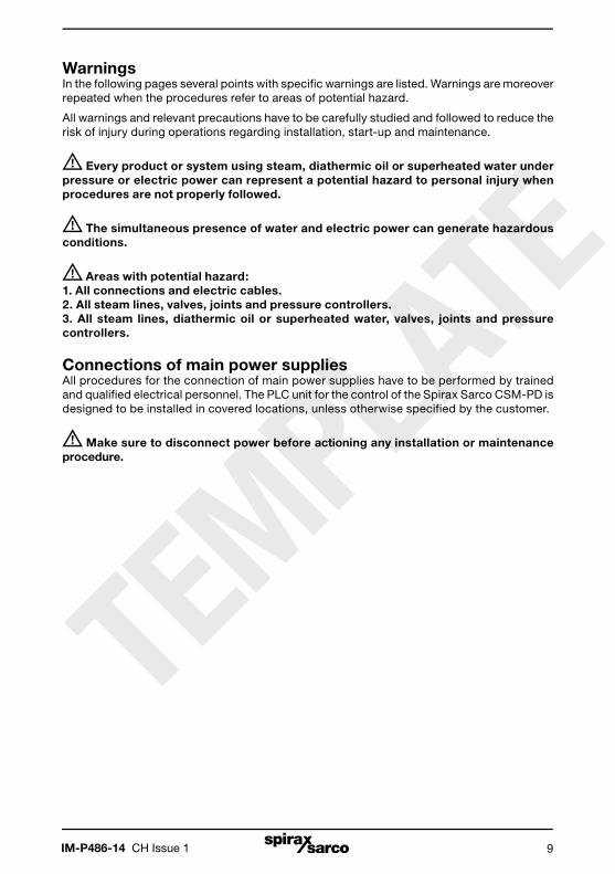
WarningsIn the following pages several points with specific warnings are listed. Warnings are moreover repeated when the procedures refer to areas of potential hazard.
All warnings and relevant precautions have to be carefully studied and followed to reduce the risk of injury during operations regarding installation, start-up and maintenance.
Every product or system using steam, diathermic oil or superheated water under pressure or electric power can represent a potential hazard to personal injury when procedures are not properly followed.
The simultaneous presence of water and electric power can generate hazardous conditions.
Areas with potential hazard:1. All connections and electric cables.2. All steam lines, valves, joints and pressure controllers.3. All steam lines, diathermic oil or superheated water, valves, joints and pressure controllers.
Connections of main power suppliesAll procedures for the connection of main power supplies have to be performed by trained and qualified electrical personnel. The PLC unit for the control of the Spirax Sarco CSM-PD is designed to be installed in covered locations, unless otherwise specified by the customer.
Make sure to disconnect power before actioning any installation or maintenance procedure.

IM-P486-14 CH Issue 110
TEMPLATE
DescriptionThe PLC control and safety unit is intelligent equipment designed to start-up, control and operate, either in local mode or by ultimate means of a remote system (DCS - Distribution Control System or BMS - Business Management System).
3. Control unit
Location and identification of componentsFront panel
IG : Main power switchThis power disconnect device is equipped with a door locking handle that breaks the three phases of the input voltage and allows to open the cabinet door only when it is in the 'OFF' position.
Attention: the user must provide an external stop circuit outside of the drive circuitry. The circuit must disable the system in case of improper operation or for unit maintenance. Failure to observe this precaution could result in a hazardous situation or in injury for employed personnel.
L1 : LED indicator
When lit (white light) it indicates that
the unit is powered.
PRB : Push-buttonManual reset push-button (after shutdown).
L2 : LED indicatorWhen lit (blinking red light) it indicates that the system is stopped due to intervention of one or more alarms.
PLCPLC control
unit.
PE : Push-buttonEmergency stop push-button.
S1 : Selector
(lockable)for either
Manual orAutomaic
control.
Fig. 1

IM-P486-14 CH Issue 1 11
TEMPLATE
Inside cabinet
(See the attached wiring diagram supplied with the unit)
Fig. 2
PLC : Control unit with analog and digital inputs and
outputs.
RL : Relays.
AL1 : 24 Vdc power
supply.
I1 - I2 : Automatic switch for power supply of primary and secondary circuit.
FS - RE : Fuses and Resistors.
IG : Main power switch.

IM-P486-14 CH Issue 112
TEMPLATE
The PLC based unit is designed to provide control of: Temperature, Water level and of all Alarm limits of the Spirax Sarco CSM-PD.
The control unit is equipped with a video interface displaying screens with graphics of the tank and also selective parts, e.g. error and functional messages, etc.
Set point values can be displayed and modified during operation using functional keys.
4. Control features
Two LED’s respectively indicate the RUN status of the program (Green light) and the presence of at least one alarm (Red light). The control unit enables the setting of all operating parameters by means of different display screens. The PLC control unit also provides a visual alarm signal.
In addition to the automation of a single CSM-PD, the system allows the achievement of computerized networks with PC’s, PLC’s and microprocessor based systems thus permitting a high level of integration among automation systems applied to the various units present in the plant. The supervision system can be considered in terms of visualization of data relevant to equipment, configuration and production control.
The control unit is equipped with a main power switch and is housed in a metal cabinet with protection degree IP54 and with dimensions of 700 x 500 x 250 mm.

IM-P486-14 CH Issue 1 13
TEMPLATE
All electrical connections have to be carried out by trained and qualified installation electricians. It is important to verify that the main power switch is in the 'OFF' position before connecting the line voltage.
The installer has to route the power cables, reach the terminals located on the main power switch mounted on the panel and run the ground wire to the earth ground terminal.
The units are normally wired for a single-phase input voltage of 230 Vac 50Hz. If necessary other input voltages can be provided on request.
Attention: Prior to drilling a hole in the panel for the connection of power cables, carefully open the panel door and verify there are no impediments inside the panel. Make sure to avoid contacts with drilling residuals or with any mechanical part left on the base or on the transformer or on the switch.
Input voltage: 230 Vac – 50 Hz
Output contacts: 3 A – 230 V for inductive loads
Output contacts: 6 A – 230 V for resistive loads
Operational ambient temperature: Minimum –20°C to a Maximum +55°C
Relative Humidity (RH): from 5% to 95% non-condensing
LCD display with energy saving dimmer function: 4 lines each with 16 characters
5. External connection
6. Main power supply
IM-P486-14 CH Issue 114
TEMPLATE
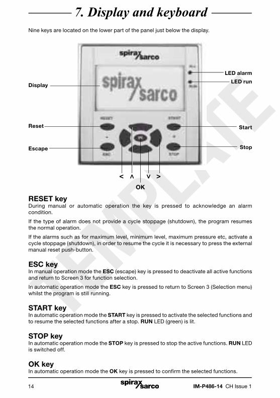
Nine keys are located on the lower part of the panel just below the display.
7. Display and keyboard
RESET keyDuring manual or automatic operation the key is pressed to acknowledge an alarm condition.
If the type of alarm does not provide a cycle stoppage (shutdown), the program resumes the normal operation.
If the alarms such as for maximum level, minimum level, maximum pressure etc, activate a cycle stoppage (shutdown), in order to resume the cycle it is necessary to press the external manual reset push-button.
ESC keyIn manual operation mode the ESC (escape) key is pressed to deactivate all active functions and return to Screen 3 for function selection.
In automatic operation mode the ESC key is pressed to return to Screen 3 (Selection menu) whilst the program is still running.
START keyIn automatic operation mode the START key is pressed to activate the selected functions and to resume the selected functions after a stop. RUN LED (green) is lit.
STOP keyIn automatic operation mode the STOP key is pressed to stop the active functions. RUN LED is switched off.
OK keyIn automatic operation mode the OK key is pressed to confirm the selected functions.
Display
Reset
Escape
LED alarm
LED run
Start
Stop
< >OK
IM-P486-14 CH Issue 1 15
TEMPLATE
< keyIn manual and automatic operation mode the < key is pressed to decrease the set point values.
> keyIn manual and automatic operation mode the > key is pressed to increase the set point values.
keyIn manual and automatic operation mode the key is pressed to select the functions to be activated and to select the relevant parameter to be programmed. In automatic operation mode this key is pressed to return from the set point programming screen to that displaying the values of the variables (pressure and level).
keyIn manual and automatic operation mode the key is pressed to select the functions to be activated and to select the relevant parameter to be programmed. In automatic operation mode this key is pressed to return from the screen displaying the values of the variables (pressure and level) to the set point programming screen.

IM-P486-14 CH Issue 116
TEMPLATE
Initial screenPowering the unit the display will show Screen 1:
Screen 1 Screen 2
By pressing the key Screen 2 will be displayed.
By pressing the key again, Screen 3 will be displayed where it will be possible to select one out of four operation modes (Manual - Automatic - Historical alarms - Parameters).
Press the and keys to move down and up for the selection of the desired operation mode.
Then press the OK key to confirm and store the choice and enter the selected mode.
Screen 3

IM-P486-14 CH Issue 1 17
TEMPLATE
Upon selection of the manual operation mode, by pressing the key again, Screens 4 and 5 are accessed in sequence.
By pressing the key the reverse selection is obtained.
8. Manual mode
Screen 5Temperature control mode
Screen 4Feedwater control mode
General considerations in manual modeThe above are active funtions; by accessing Screen 5 and utilising the and keys, it is possible to access subsequent screens and select other functions. The operation of the previously selected function however, is left active. If instead it is desired to deactivate the just selected function, before proceeding with other functions, the < (OFF) key or the < (-) key have to be pressed until the value '0' of the programmed set is reached.
In order to deactivate with a unique command all active functions and return to Screen 3 for function selection, it is necessary to press the ESC key.
During the operation in manual mode the alarm locks (safety switches) are active.
By pressing the emergency push-button all active functions will be cleared and the relevant alarm will be displayed. Pressing the same push-button again, Screen 4 (feedwater manual control) will be displayed to allow the selection of the function to be activated by pressing the and keys.

IM-P486-14 CH Issue 118
TEMPLATE
Manual control of the feedwater
The supplied level transmitter has a working range defined by the specifications of each tank. It is important that the working range of the transmitter matches that programmed in the control unit.
There are three types of level control:
The three types are defined as:Type [0], Type [1] and Type [2]
Type [0] - The level control is an on-off type of control provided by a level switch device. When the preset limits are exceeded this level switch controls the start-up or the stoppage of the feedwater pump or the opening and the closure of the isolation valve.
Type [1] - It is a continuous control acting on the feedwater pump by means of a level control and measuring unit. The pump, when provided, will run continuously in cycle.
Type [2] - It is a continuous control that through a level control and measuring unit operates on the frequency changer to change the flow of feedwater.
In order to manually control the feedwater proceed with the following steps:
Turn the 'cycle' selector to position '0' (Manual control) and select Screen 4 (Control display).
If the selector is turned to position '1' (Automatic control) an alarm status is obtained as displayed on Screen 6. In this situation switch the selector to position '0' to reach the condition displayed on Screen 4.
Screen 4 Screen 6

IM-P486-14 CH Issue 1 19
TEMPLATE
Once the manual mode is selected press the < (- ) and (+) > keys to increase or decrease the valve opening and consequently adjust the level. The display will indicate:
Level type [0] Valve graphic completely displayed (open).
Level type [1] The value in % of the control valve position and the value of the measured level.
Level type [2] The value in % corresponding to the required pump speed and the value of the measured level.
During operation, the following alarm conditions can occur:
- Measurement alarm (when a 4-20 mA transmitter is provided).
- Maximum level alarm.
- Maximum pressure alarm.
- Pump stoppage alarm.
In the case of an alarm condition occuring, for example see Screens 7 and 8, the stop valve of the water line will close.
The operation will be stopped and the general alarm will light up. The alarm type indicated on the screen will be cleared by pressing the RESET button on the panel keyboard. The general alarm remains active and the LED will blink. It is necessary to remove the cause of the alarm before re-opening the valve. Then press the external manual reset push-button.
In order to resume the operation of level control press the < (-) and (+) > or <OFF ON> keys.
Screen 7 Screen 8

IM-P486-14 CH Issue 120
TEMPLATE
Manual control of the temperature
The supplied temperature transmitter has a working range matched to the specification of each tank. Normal ranges are 0 – 90, 0 – 100 or 0 – 120 ºC. It is important that the working range of the transmitter matches that programmed in the control unit.
For manual control of the temperature proceed with the following steps:
Turn the 'cycle' selector to position '0' (Manual control) and select Screen 5 (temperature control).
If the selector is turned to position '1' (Automatic control) an alarm status is obtained as displayed on Screen 6.
In this situation switch the selector to position '0' to reach the condition displayed on Screen 5.
Screen 5
Screen 6

IM-P486-14 CH Issue 1 21
TEMPLATE
Select Screen 5 with and keys.
Press (+) > and < (-) keys to increase or decrease the steam valve position. The display will indicate the opening value of the valve in % and the steam temperature value in ºC. When the required value of the position exceeds the limit of '0', the on-off solenoid valve of the primary steam will be open. Meanwhile the Screen will show the complete graphic of the valve to indicate the working condition of the same.
The stoppage and the closure of the isolation valve of steam are instead indicated with the external profile only of the valve graphic. Screen 5 is supposed to be displayed during the normal operation in manual mode.
During operation, the following alarm conditions can occur:- Transmitter alarm.- Maximum level alarm.- Minimum level alarm.- Maximum pressure alarm.
When an alarm condition occurs, as displayed on Screens 9 and 10, the steam control valve will close. The operation will be stopped and the general alarm will light up.
To acknowledge the alarm press the RESET key. Screen 4 will be displayed (manual control of feedwater) whilst the general alarm remains active. It is necessary to remove the cause of the alarm before re-opening the valve. Then press the external manual reset push-button.
Press the and keys to access Screen 5, then press the < (-) and (+) > keys to resume the operation of the valve.
Screen 9 Screen 10

IM-P486-14 CH Issue 122
TEMPLATE
After a Start-up or Manual Mode press the key and access Screen 3 where it will be possible to select one out of four operation modes (Manual - Automatic - Historical alarms - Parameters).
Press the and keys to move down or up and select the Automatic Mode (Screen 3).
Then press the OK key to confirm and store the choice and enter the selected mode.
9. Automatic mode
Screen 3
By pressing the key in Screen 11 will allow access to various options. By pressing the key the reverse selection is obtained. This screen is used for local programming of set point values.
Screen 11BScreen 11A

IM-P486-14 CH Issue 1 23
TEMPLATE
Temperature control
Setting of the desired value (set-point)
The supplied temperature transmitter has a working range matched to the specification of each tank. Normal ranges are 0 – 90, 0 – 100 or 0 – 120 ºC. It is important that the working range of the transmitter matches that programmed in the control unit.
Set point values exceeding the maximum limit of the transmitter range are not accepted by the system.
The maximum acceptable values are stored in the area of configuration parameters. They can be modified only by authorized personnel via a password.
Press the < or > keys until the set point value of pressure required by the generator is displayed on the screen or press the OK key.
The digit of the set point value in decimal will blink.
Press the or keys to enter the desired value.
Then press the < key and move the cursor to the digit which displays the unit value required.Press the or keys to enter the desired value.
Then press the < key and move the cursor to the digit which displays the unit value required in tenths (if provided).Press the or keys to enter the desired value.
Finally press the OK key and afterwards the V key to progress to the next setting.
Note: The function will be disabled by setting the set point value to zero (0).
Screen 11A
IM-P486-14 CH Issue 124
TEMPLATE
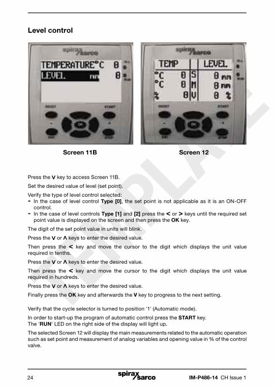
Level control
Press the key to access Screen 11B.
Set the desired value of level (set point).
Verify the type of level control selected:- In the case of level control Type [0], the set point is not applicable as it is an ON-OFF control.- In the case of level controls Type [1] and [2] press the < or > keys until the required set point value is displayed on the screen and then press the OK key.
The digit of the set point value in units will blink.
Press the or keys to enter the desired value.
Then press the < key and move the cursor to the digit which displays the unit value required in tenths.
Press the or keys to enter the desired value.
Then press the < key and move the cursor to the digit which displays the unit value required in hundreds.
Press the or keys to enter the desired value.
Finally press the OK key and afterwards the V key to progress to the next setting.
Verify that the cycle selector is turned to position '1' (Automatic mode).
In order to start-up the program of automatic control press the START key.The 'RUN' LED on the right side of the display will light up.
The selected Screen 12 will display the main measurements related to the automatic operation such as set point and measurement of analog variables and opening value in % of the control valve.
Screen 12Screen 11B
IM-P486-14 CH Issue 1 25
TEMPLATE
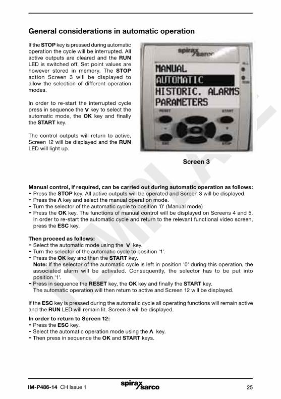
General considerations in automatic operation
If the STOP key is pressed during automatic operation the cycle will be interrupted. All active outputs are cleared and the RUN LED is switched off. Set point values are however stored in memory. The STOP action Screen 3 will be displayed to allow the selection of different operation modes.
In order to re-start the interrupted cycle press in sequence the key to select the automatic mode, the OK key and finally the START key.
The control outputs will return to active, Screen 12 will be displayed and the RUN LED will light up.
Manual control, if required, can be carried out during automatic operation as follows:- Press the STOP key. All active outputs will be operated and Screen 3 will be displayed.- Press the key and select the manual operation mode.- Turn the selector of the automatic cycle to position '0' (Manual mode)- Press the OK key. The functions of manual control will be displayed on Screens 4 and 5. In order to re-start the automatic cycle and return to the relevant functional video screen, press the ESC key.
Then proceed as follows:- Select the automatic mode using the key.- Turn the selector of the automatic cycle to position '1'.- Press the OK key and then the START key. Note: If the selector of the automatic cycle is left in position '0' during this operation, the associated alarm will be activated. Consequently, the selector has to be put into position '1'.- Press in sequence the RESET key, the OK key and finally the START key. The automatic operation will then return to active and Screen 12 will be displayed.
If the ESC key is pressed during the automatic cycle all operating functions will remain active and the RUN LED will remain lit. Screen 3 will be displayed.
In order to return to Screen 12:- Press the ESC key.- Select the automatic operation mode using the key.- Then press in sequence the OK and START keys.
Screen 3

IM-P486-14 CH Issue 126
TEMPLATE
As described in the manual operation mode all the block alarms are active during the automatic cycle. In detail they are:
Block off the feedwater control when one of the following alarms occurs:- Stoppage of water pump.- Minimum level of storage.- Level transmitter.- Maximum level.- High temperature.
Block off the temperature control when one of the following alarms occurs:- Temperature transmitter.- Minimum level.- Maximum level.- High temperature.
The cycle will be interrupted by pressing the emergency push-button during the automatic operation, all active functions will be cleared and the relevant alarm will light up.
10. Alarms and blocks
In order to resume the automatic operation reset the emergency push-button and press the START key.
The cycle will restart and the RUN LED will therefore light up.
Screen 13

IM-P486-14 CH Issue 1 27
TEMPLATE
1. Parameters not protected by a password
Actions of the temperature controller
To set the controller actions proceed as follows:
Step 1 - Access Screen 3 (operation mode selection). Press the and keys to select the item 'PARAMETERS'.
By then pressing the OK key Screen 14 will be displayed:
11. Configuration
Screen 14
Enter the desired value of the proportional band (gain) constant (0 to 100%) using the < - and + > keys.
Note: the entered value will be stored until a successive modification.

IM-P486-14 CH Issue 128
TEMPLATE
Enter the desired value of the integral action constant (0 to 10) using the < - and + > keys.
Note: the entered value will be stored until a successive modification.
For values set near to '0' or to '10' this action will be fast or slow respectively.
Step 3 - Press the key to access the next screen, Screen 16.
In case of control with only the proportional band action, enter the desired value of the power reset constant (0 to 100%) using the < - and + > keys.
Note: the entered value will be stored until a successive modification.
This setting is only possible when the constant of the integral action is set to '0'.
Screen 15
Screen 16
Step 2 - Press the key to access the next screen, Screen 15.

IM-P486-14 CH Issue 1 29
TEMPLATE
Actions of the level controller (ON-OFF control excluded)
To set the controller actions proceed as follows:
Step 1 - Press the key to access the next screen, Screen 17.
Enter the desired value of the proportional band (gain) constant (0 to 100%) using the < - and + > keys.
Note: the entered value will be stored until a successive modification.
Step 2 - Press the key to access the next screen, Screen 18.
Screen 17
Screen 18Enter the desired value of pre-alarm for level using the < - and + > keys. This is an absolute value ranging from '0' to '1000' (zero and full-scale values of the level transmitter).
The cycle will not be blocked when this alarm occurs.

IM-P486-14 CH Issue 130
TEMPLATE
2. Parameters protected by a password
Press the key to access the next screen, Screen 19.
To enter the three digit password proceed as follows:- Press the key (the value 3 is entered in the first digit).
Press the OK key to access the following Screens to set these parameters.
Screen 19
Use Screen 20 to enter the full-scale values of pressure and level according to the installed transmitters.
Screen 20

IM-P486-14 CH Issue 1 31
TEMPLATE
To enter the temperature value:- Press the OK key twice - The digit of the full-scale value in decimal will blink.- Press the or keys to enter the desired value.- Then press the < key and move the cursor to the digit which displays the unit valve required - The value in units of the full-scale will blink.- Press the or keys to enter the desired value.- Press the OK key upon termination of the setting.
To enter the level value:- Press the OK key twice - The preset value of the full-scale will blink (maximum value 999 mm).- Press the or keys to enter the desired value in the blinking digit.- Using the <- and +> keys move into the digit positions still to be set.- Press the or keys to enter each desired value.- Upon termination of this setting press in sequence the OK and ESC keys and finally the key.- The following screen, Screen 21 will be displayed.- Press the key and Screen 22 will be displayed.
Screen 21 is used to enter the values of zero and span values for transmitter linearisation process.
Press the OK key to access the value selection mode, use the arrows to select the start or end value, and press the OK key to confirm your choice and proceed to press the ESC key to leave this editing selection.
When your choice has been confirmed use the arrows to change the digits and to increasevalues, press the OK key to confirm your choice, and press the ESC key to undo.
Default value for the 4 - 20 mA signal are:Start - 210End - 1019
Screen 21 Screen 22
IM-P486-14 CH Issue 132
TEMPLATE
Should it be necessary to return the equipment for repairs please contact our nearest Branch Office or Agent or directly:
Spirax Sarco S.r.l. Ufficio Resi - Via per Cinisello, 18 - 20054 Nova Milanese (MI)
Tel. 0362-4917.1 Fax 0362-4917307
Loss of guarantee
Total or partial disregard of the above instructions involves loss of any right of guarantee.Spirax-Sarco S.r.l. Via per Cinisello,
18 - 20054 Nova Milanese (MI) Tel.: 0362 4917.1
Fax: 0362 4917307
12. Repairs