Embed Size (px)
Citation preview
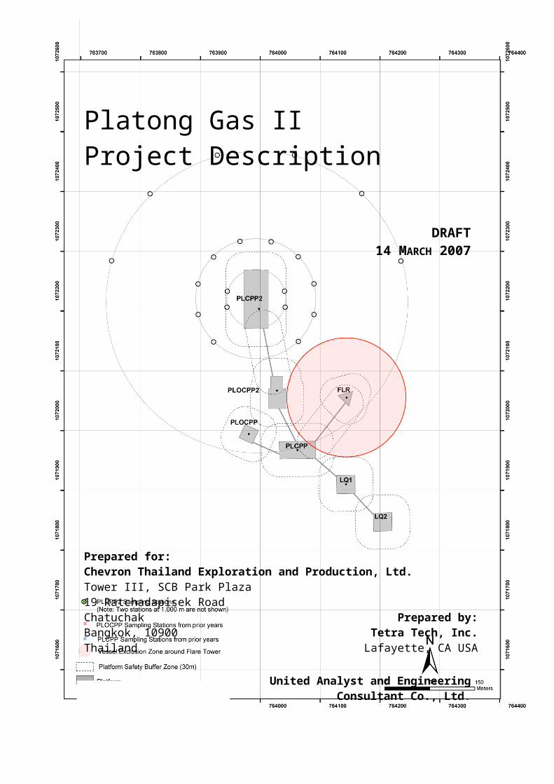
Platong Gas II Project Description
DRAFT 14 MARCH 2007
Prepared for:Chevron Thailand Exploration and Production, Ltd.Tower III, SCB Park Plaza19 Ratchadapisek RoadChatuchak Prepared by:Bangkok, 10900 Tetra Tech, Inc.Thailand Lafayette, CA USA
United Analyst and EngineeringConsultant Co., Ltd.
Bangkok, Thailand
T19588

This page intentionally left blank

Platong Gas II Project Description March 2007
1 Introduction
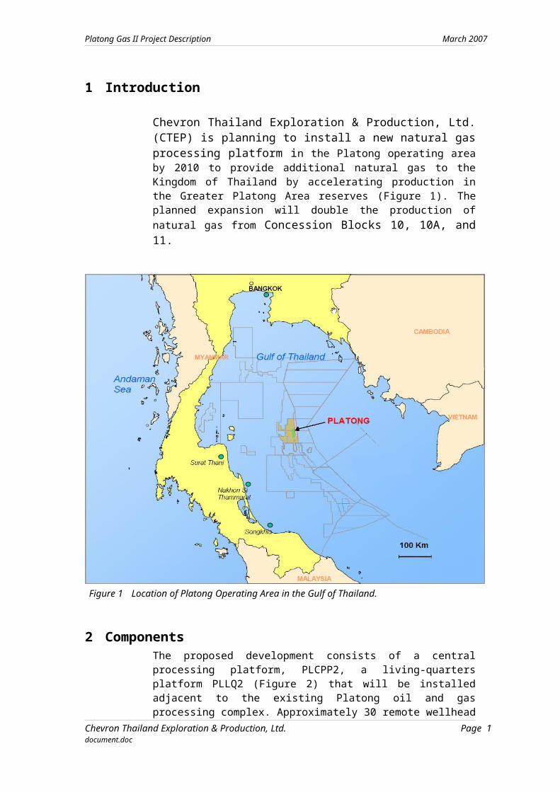
Chevron Thailand Exploration & Production, Ltd. (CTEP) is planning to install a new natural gas processing platform in the Platong operating area by 2010 to provide additional natural gas to the Kingdom of Thailand by accelerating production in the Greater Platong Area reserves (Figure 1). The planned expansion will double the production of natural gas from Concession Blocks 10, 10A, and 11.
Figure 1 Location of Platong Operating Area in the Gulf of Thailand.
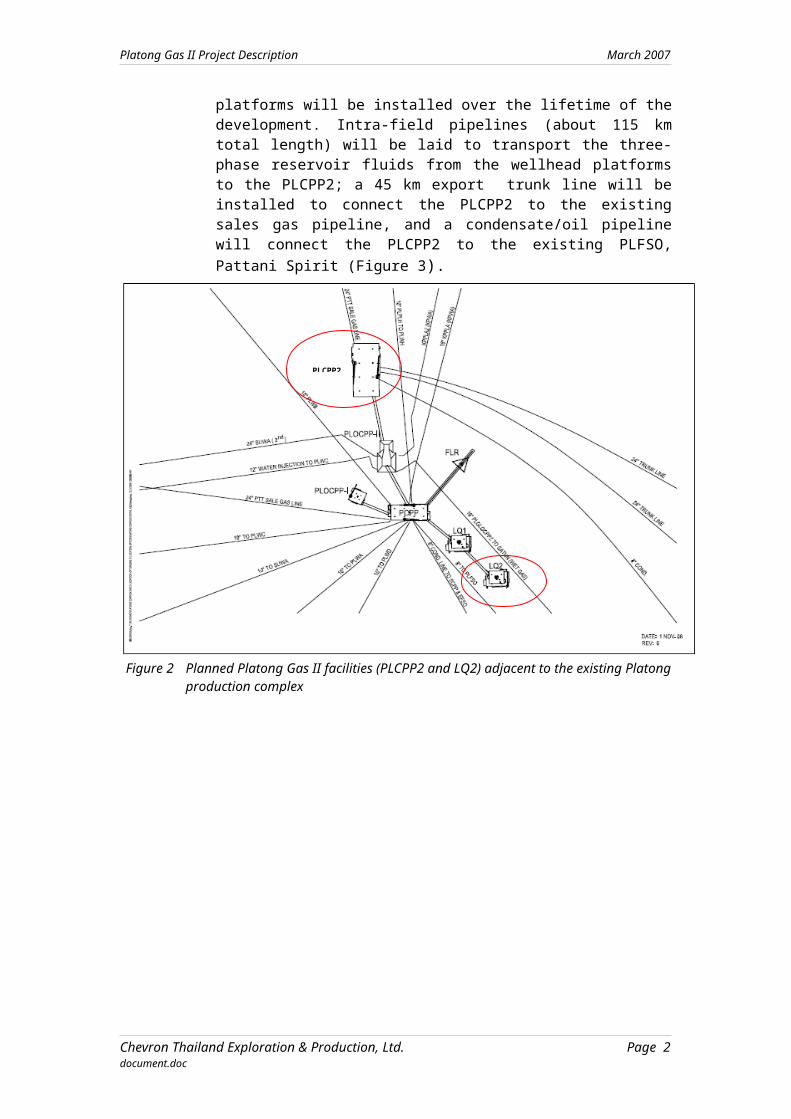
2 ComponentsThe proposed development consists of a central processing platform, PLCPP2, a living-quarters platform PLLQ2 (Figure 2) that will be installed adjacent to the existing Platong oil and gas processing complex. Approximately 30 remote wellhead platforms will be installed over the lifetime of the development. Intra-field pipelines (about 115 km total length) will be laid to transport the three-phase reservoir fluids from the wellhead platforms to the PLCPP2; a 45 km export trunk line will be installed to connect the PLCPP2 to the existing sales gas pipeline, and a condensate/oil pipeline will connect the PLCPP2 to the existing PLFSO, Pattani Spirit (Figure 3).
Chevron Thailand Exploration & Production, Ltd. Page 1document.doc
Platong Gas II Project Description March 2007
Figure 2 Planned Platong Gas II facilities (PLCPP2 and LQ2) adjacent to the existing Platong production complex
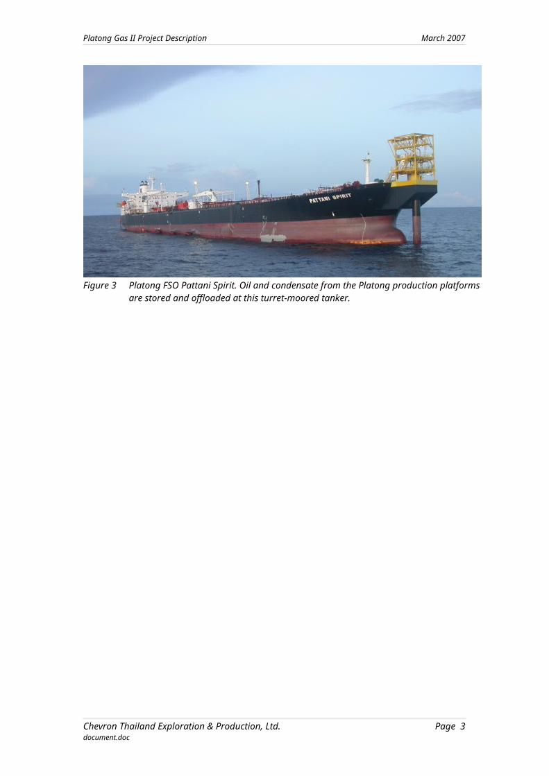
Figure 3 Platong FSO Pattani Spirit. Oil and condensate from the Platong production platforms are stored and offloaded at this turret-moored tanker.
Chevron Thailand Exploration & Production, Ltd. Page 2document.doc
PLCPP2
Platong Gas II Project Description March 2007
3 Project AlternativesThree alternative gas production capacities are being considered:
1. 250 mmscfd production using a single process train
2. 350 mmscfd production using a single process train
3. 350 mmscfd production using two process trains.
Two methods of installing the topsides structures at the proposed site are being considered:
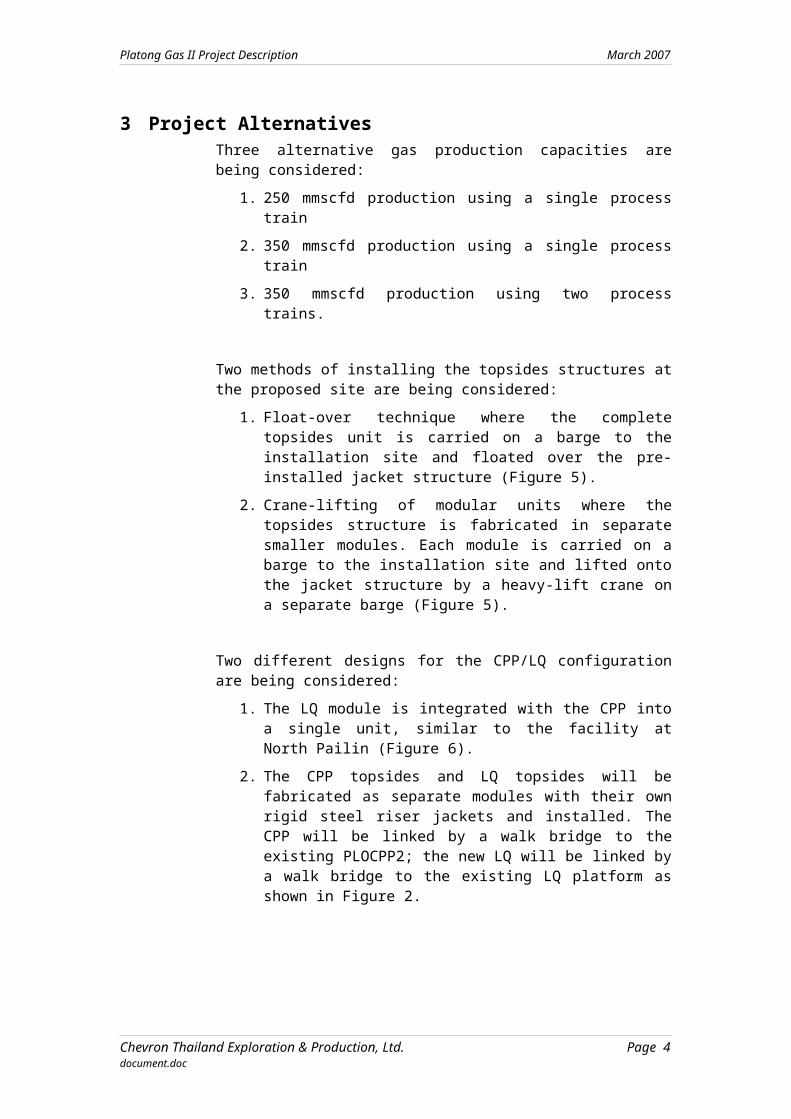
1. Float-over technique where the complete topsides unit is carried on a barge to the installation site and floated over the pre-installed jacket structure (Figure 5).
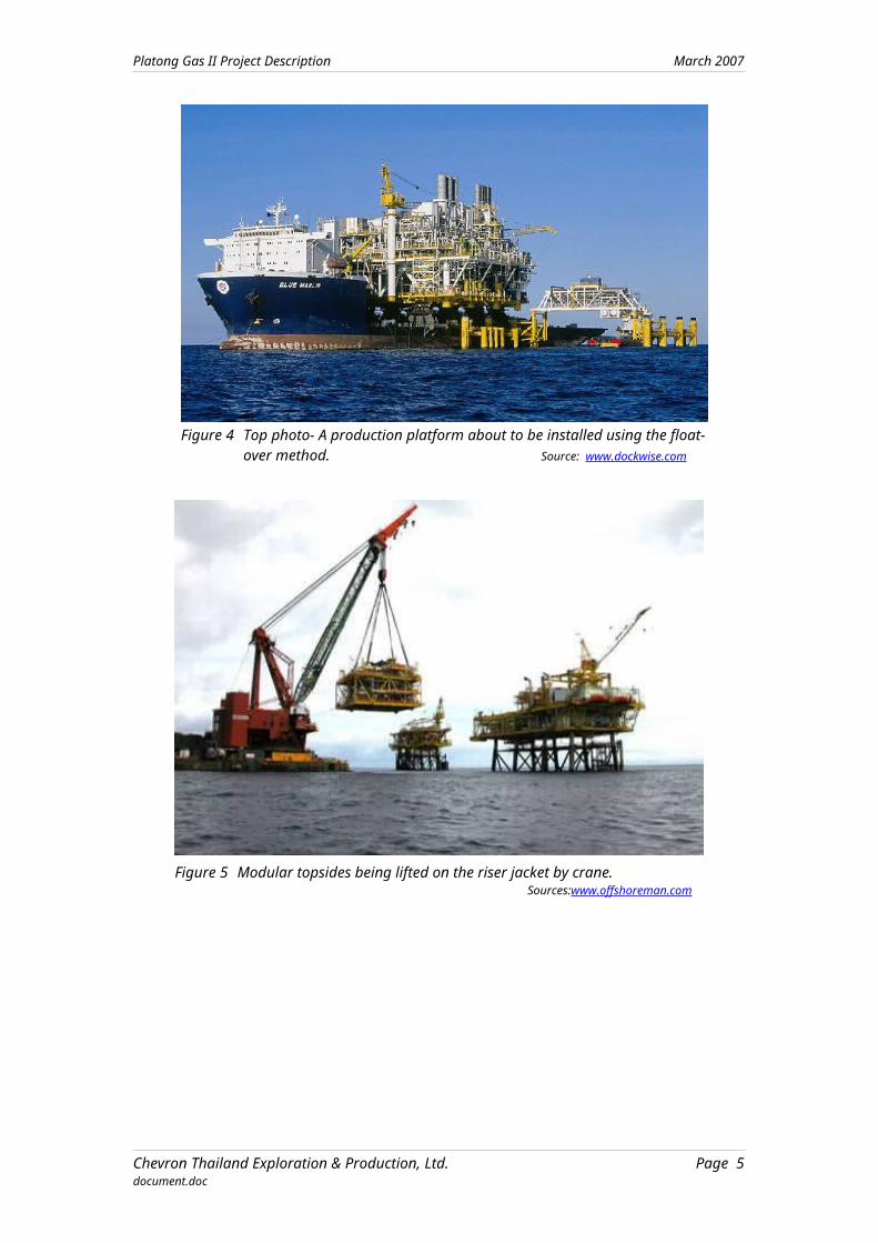
2. Crane-lifting of modular units where the topsides structure is fabricated in separate smaller modules. Each module is carried on a barge to the installation site and lifted onto the jacket structure by a heavy-lift crane on a separate barge (Figure 5).
Two different designs for the CPP/LQ configuration are being considered:
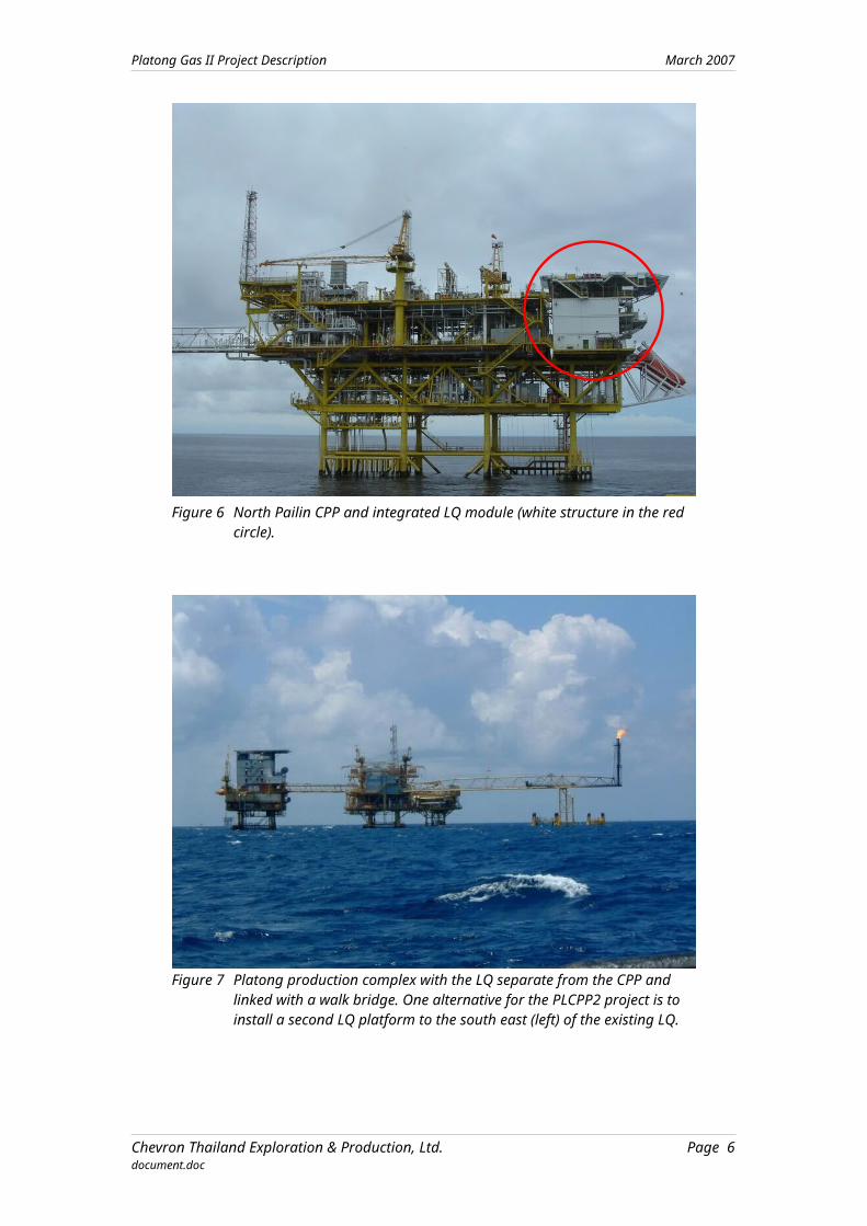
1. The LQ module is integrated with the CPP into a single unit, similar to the facility at North Pailin (Figure 6).
2. The CPP topsides and LQ topsides will be fabricated as separate modules with their own rigid steel riser jackets and installed. The CPP will be linked by a walk bridge to the existing PLOCPP2; the new LQ will be linked by a walk bridge to the existing LQ platform as shown in Figure 2.
Figure 4 Top photo- A production platform about to be installed using the float-over method. Source: www.dockwise.com
Chevron Thailand Exploration & Production, Ltd. Page 3document.doc
Platong Gas II Project Description March 2007
Figure 5 Modular topsides being lifted on the riser jacket by crane.Sources:www.offshoreman.com
Figure 6 North Pailin CPP and integrated LQ module (white structure in the red circle).
Chevron Thailand Exploration & Production, Ltd. Page 4document.doc
Platong Gas II Project Description March 2007
Figure 7 Platong production complex with the LQ separate from the CPP and linked with a walk bridge. One alternative for the PLCPP2 project is to install a second LQ platform to the south east (left) of the existing LQ.
4 CPP OverviewThe CPP will be comprised of one or two treatment trains and ancillary systems with an expected daily production capacity of between 250 – 350 mmscfd and a design capacity of 418 mmscfd.
A schematic diagram of the treatment systems planned for the CPP is shown in Figure 8. The yellow components in indicate the gas treatment sequence. The production fluid from the remote wellhead platforms first passes through the inlet separator where it is separated into the gas and liquid phases. After separation, the gas is pressurized and dried. Some gas is diverted to be used as fuel for process heaters and power generation for the treatment processes. The remaining gas is passed through a mercury removal unit and into the sales gas export pipeline.
After separation from the gas, the production liquids are directed through a three-phase separator unit. The residual gas from the three-phase separator is returned to the inlet separator. The oil and condensate are stabilized and pumped to the condensate export pipeline. The oil and condensate treatment train is represented by the green components in Figure 8). The oil to gas production ratio is expected to be about 50 barrels of oil for each mmscf of gas.
The produced water is also separated at the three-phase separator, directed through the water treatment system to reduce the remaining solids and then to the water injection pumps for reinjection into depleted reservoirs (the blue
Chevron Thailand Exploration & Production, Ltd. Page 5document.doc
Platong Gas II Project Description March 2007
components in Figure 8). Produced water is expected to be reinjected at a rate of 100 barrels for every 1 mmscf of gas production.
Reinjection is the primary produced water disposal process. As a back-up system, the produced water will be diverted to the produced water treatment system on PLCPP. This treatment system is designed to reduce mercury, arsenic and petroleum hydrocarbons in the produced water before it is discharged overboard.
Figure 8 Schematic diagram for PLCPP2 treatment systems. Gas treatment is shown in yellow, oil/condensate treatment in green, produced water treatment in blue.
5 LQ OverviewA separate LQ facility installed on a rigid steel jacket southeast of the existing LQ is one alternative under consideration. The design of the new LQ will be similar to the existing Platong LQ. The facility will be comprised of 4 levels of accommodation decks with catering and recreation facilities for a minimum of 140 workers, housed in 2- or 4-man rooms. Maintenance shops, a warehouse area, and a boat deck will be located below the accommodation levels. A helideck will be incorporated into the roof of the accommodation module. The LQ platform will be connected to the existing LQ by a steel walk bridge.
The second alternative for the LQ module is to integrate the module with the PLCPP2 on the same riser jacket. The components of the LQ will be similar to those described for the separate LQ facility. The CPP/LQ module will be installed to the north of the existing PLOCPP2 and it will be connected with a walk bridge to the PLOCPP2.
6 Project ScheduleThe initial engineering design and commercial feasibility studies for the PLCPP2 facility has commenced. Production of natural gas is scheduled to start between March 2010 and March 2011 (Figure 9). There is substantial uncertainty in the schedule because of many factors, including economic and regulatory considerations including approval of the environmental impact
Chevron Thailand Exploration & Production, Ltd. Page 6document.doc
Platong Gas II Project Description March 2007
assessment report. The design and fabrication of the LQ topsides module and jacket are scheduled to start in the second quarter of 2007 to meet the planned LQ installation date of December 2008.
The PLCPP2 design is also scheduled to start in the second quarter of 2007 but fabrication may not be completed until mid-2010. Installation is planned to begin no earlier that the fourth quarter of 2009 and to be completed no later than the second quarter of 2010.
Jul-2
006
Sep-2
006
Dec-2
006
Mar
-200
7
Jul-2
007
Sep-2
007
Dec-2
007
Mar
-200
8
Jun-
2008
Sep-2
008
Dec-2
008
Mar
-200
9
Jun-
2009
Sep-2
009
Dec-2
009
Mar
-201
0
Jun-
2010
Sep-2
010
Dec-2
010
Mar
-201
1
Jun-
2011
FEED Contract
GSA Negotiations Completed
CPP - Procure Long Lead Equipment
LQ - Jacket - Design, Fab & Install
LQ - Topsides - Design, Fab & Install
LQ - Commissioning
CPP - Detailed Design
Mobilize Fabrication Contractor
CPP - Topsides Fabrication
CPP - Jacket Fabrication
CPP - Jacket Installation
CPP - Topsides Load-out & Transportation
CPP - Topsides Installation & Precommissioning
CPP - Commissioning
First Gas (Range)
Figure 9 Preliminary project schedule for the design, fabrication, and installation of PLCPP2, assuming a separate LQ facility is installed adjacent to the existing PLLQ.
Chevron Thailand Exploration & Production, Ltd. Page 7document.doc


![FM4XXX DATA Protocol Description v1[1].1](https://img.pdfslide.us/doc/110x75/55cf9749550346d03390c5f7/fm4xxx-data-protocol-description-v111.jpg)
![SYMC Eu IV DTC Description V1 070307[1]](https://img.pdfslide.us/doc/110x75/55cf96be550346d0338d808d/symc-eu-iv-dtc-description-v1-0703071.jpg)