Embed Size (px)
Citation preview

51925-88
Platinum Series CombinationSodium Electrode
Model 51925-00
MANUAL
© Hach Company, 1999. All rights reserved. Printed in the U.S.A. ap/dk 2/99 1edap/dk 9/99 rev 2

TRADEMARKS OF HACH COMPANY
AccuGrow®AccuVac®
AccuVer™
Add-A-Test™
AgriTrak™
AluVer®
AmVer™
APA 6000™
AquaChek®
AquaTrend®
BariVer®
BODTrak™
BoroTrace™
BoroVer®
C. Moore Green™
CA 610™
CalVer®
ChromaVer®
ColorQuik®
CoolTrak®
CuVer®
CyaniVer®
Digesdahl®
DithiVer®
Dr. F. Fluent™
Dr. H. Tueau™
DR/Check™
EC 310™
FerroMo®
FerroVer®
FerroZine®
FilterTrak 660™
Formula 2533™
Formula 2589™
Gelex®
H2O University™
H2OU™
Hach Logo®
Hach One®
Hach Oval®
Hach.com™
HachLink™
HexaVer®
HgEx™
HydraVer®
ICE-PIC™
IncuTrol®
Just Add Water™
LeadTrak®
m-ColiBlue24®
ManVer®
MolyVer®
Mug-O-Meter®
NetSketcher™
NitraVer®
NitriVer®
NTrak®
OASIS™
On Site Analysis.Results You Can TrustSM
OptiQuant™
OriFlow™
OxyVer™
PathoScreen™
PbEx®
PermaChem®
Phillip D. Glass™
PhosVer®
Pocket Colorimeter™
Pocket Pal™
Pocket Turbidimeter™
Pond In Pillow™
PourRite™
PrepTab™
ProNetic™
Pump Colorimeter™
QuanTab®
Rapid Liquid™
RapidSilver™
Ratio™
RoVer®
™
Simply AccurateSM
SofChek™
SoilSys™
SP 510™
Spec ™
StablCal®
StannaVer®
SteriChek™
StillVer®
SulfaVer®
Surface Scatter®
TanniVer®
TenSette®
Test ‘N Tube™
TestYes!
TitraStir®
TitraVer®
ToxTrak™
UniVer®
VIScreen™
Voluette®
ZincoVer®
ZincoVer®
sension
√
SM
SINGLET™
2

...
......7
...9
................11......11.....12......13......13
....14
....14
......14
...
7.............
.............
7.....40......40......42
57............5
TABLE OF CONTENTS
SPECIFICATIONS..................................................................................................................5
SAFETY PRECAUTIONS ..................................................................................................
SECTION 1 GETTING STARTED .....................................................................................1.1 Electrode Description......................................................................................................91.2 Electrolyte Description..................................................................................................101.3 Preparing the Electrode for Use ...................................................................................
1.3.1 Combination Electrode Components..................................................................1.3.2 Preparing the Reference Half Cell .......................................................................1.3.3 Preparing the Sensing Bulb ................................................................................
1.4 Conditioning the Electrode...........................................................................................1.4.1 Normal Conditioning
(For routine measurements in samples 1 mg/L Na+ or greater): .........................1.4.2 Low Ionic Strength Conditioning
(For measurements in samples containing less than 1.0 mg/L Na+): ..................1.5 Checking the Sodium Electrode...................................................................................1.6 Measuring Hints ..............................................................................................................15
SECTION 2 APPLICATIONS (sension2 & 4 meters)........................................................1Analysis Procedure.................................................................................................................19Sampling and Storage..........................................................................................................23Accuracy Check ......................................................................................................................23Method Performance...........................................................................................................25Interferences.............................................................................................................................26Notes.........................................................................................................................................27Analysis Procedure.................................................................................................................28Sampling and Storage..........................................................................................................33Accuracy Check ......................................................................................................................33Method Performance...........................................................................................................35Interferences.............................................................................................................................35
SECTION 3 ANALYTICAL METHODS (mV meters) ......................................................3Required Apparatus and Solution for Direct Measurement Method...................................Preparing Standards for Direct Measurement Method.......................................................Preparing a Calibration Curve............................................................................................
SECTION 4 ELECTRODE MAINTENANCE ...................................................................4.1 Storing the Electrode:....................................................................................................574.2 Cleaning the Electrode ................................................................................................8
3

TABLE OF CONTENTS, continued
59.....................
65...... 65
. 69
.. 75
..... 77
.....
SECTION 5 ELECTRODE THEORY ................................................................................5.1 Theory of Operation.....................................................................................................595.2 Temperature Effects ...................................................................................................... 605.3 Response Time............................................................................................................... 615.4 Ionic Strength Effects ..................................................................................................615.5 Interferences....................................................................................................................... 63
SECTION 6 TROUBLESHOOTING ..................................................................................6.1 General Troubleshooting .............................................................................................
ELECTRODE SERVICE REQUEST QUESTIONNAIRE....................................................
GLOSSARY............................................................................................................................. 71
GENERAL INFORMATION .............................................................................................
HOW TO ORDER ..............................................................................................................
REPAIR SERVICE .............................................................................................................78
WARRANTY........................................................................................................................... 79
4

SPECIFICATIONS
Specifications are subject to change without notice.
Cable ConnectorBNC
DimensionsTip Diameter: 12 mmTip Length: 115 mmTotal Length: 240 mm with dispenserCable Length: 1.0 m (36 in.)
Electrode Resistance<1400 Mohms @ 30 °C (new)
Electrode TypeCombination with Ag/AgCl reference
Linear Region1 mg/L to saturation
Minimum Sample Volume25 mL
Range0.010 mg/L Na+ to saturated solutionSample pH can range from 4 to 14
Response TimeBelow 1.0 mg/L, 5–10 minutesAbove 1.0 mg/L, 1–2 minutes
Slope58 ±3 mV @ 25 °C
Storage Solution1 N NaCl Sodium Electrode Storage Solution
Temperature RangeRoutine Use: 0 to 50 °COccasional Use: 0 to 80 °CStorage: -40 to 60 °C
5

6

SAFETY PRECAUTIONS
7

8

vedle
he
the
SECTION 1 GETTING STARTED
1.1 Electrode DescriptionThe Platinum Series Combination Sodium Electrode (Figure 1) isa reliable electrode designed for general purpose sodiummeasurement in all kinds of sample. Its renewable, free flowingreference junction provides fast and accurate sodiummeasurements. Diluted electrolyte and contaminants are remofrom the junction after each pump to ensure stable, reproducibreference potentials.
The electrode uses an improved sodium-selective glassmembrane containing an inner filling solution with a constantsodium ion concentration and glycerol as an antifreeze agent. Tglass is a LAS (lithium aluminosilicate) glass. Special dopingagents in the glass improve selectivity for sodium ions. Apotential develops across the membrane that is proportional tosodium concentration in the standard or sample.
Figure 1 Platinum Series Combination Sodium Electrode, Model Number 51925-00
9
SECTION 1, continued
tial
her
ade
re
ma
g
ing
y
.
The ideal sodium ion selective electrode responds (has a potenacross the glass membrane) only to sodium ions. However,sodium electrodes are not perfectly selective and respond to otions such as silver, hydrogen, lithium, ammonium, andpotassium. The industry standard sodium glass electrode is mof NAS 11-18 glass that is 500–2000 times more sensitive tosodium ions than to potassium ions. The Hach glass has aselectivity coefficient of greater than 20,000 for sodium overpotassium. Linearity, response speed, and conditioning time aalso improved.
The Sodium Combination Electrode incorporates a glass sodiuhalf-cell and a reference half-cell. The reference half-cell usessilver–silver chloride reference element in a specially designedfree-diffusion junction. The reference element is encased inTeflon tubing.
Electrolyte flows out through the open end of the referenceelement and into the sample solution without restriction.Traditional porous junctions often become clogged byprecipitated silver chloride. This can cause large and unknownjunction potentials that result in measurement errors. Hach’spatented free-flowing reference system produces fast,stable potentials.
1.2 Electrolyte DescriptionThe Ammonium Chloride electrolyte is formulated as amedium-viscosity gel that acts as a restriction device by limitinthe release of electrolyte into the sample. Fresh referenceelectrolyte is supplied from a replaceable cartridge inside theelectrode body by depressing the dispenser button. By refreshthe electrolyte at the reference junction, Hach’s patentedreference system eliminates junction potential errors caused bclogged frits. The gelling agent is non-ionic and does notinterfere with the free flow of ions across the reference junctionProper use and care of the reference half cell extends its life.
10

SECTION 1, continued
s
pe
f
ser
ries
he
e it
1.3 Preparing the Electrode for Use
1.3.1 Combination Electrode ComponentsGeneral assembly procedures for the Platinum SeriesCombination Sodium Electrode follow. The electrode combineboth the sensing half-cell and the reference half-cell in oneelectrode body. The reference electrode is a double junction tyand uses an Ammonium Chloride Reference Electrolyte Gel.
The Platinum Series Combination Sodium electrode consists othese components (seeFigure 2), from top to bottom:
Push-Button DispenserWhen the user pushes the black dispenser button down,6 microliters of gel dispense from the bottom of the electrode,renewing the reference. When the gel is dispensed, the dispenmakes an audible “click”. To prime the electrode quickly, pressthe dispenser all the way in and turn clockwise.
Electrolyte CartridgeThe cartridge contains enough gelled electrolyte for a minimumof 250 dispensations of gel. The clear body and black pistonallow the user to see how much gel remains in the cartridge.
Electrode BodyThe electrode has several unique features. It uses the samefree-flowing reference technology as the standard Platinum Seelectrode. The electrolyte cartridge is attached to the top of theelectrode using a standard Luer taper fitting. For cleaning, astandard laboratory syringe attached to the electrode flushes tentire system.
Removable Bulb GuardLeave the tip on for normal use or remove for electrode tipcleaning or when used in small test tubes. When possible, leavon to protect the bulb.
11

SECTION 1, continued
we
e
ssis
e
Figure 2 Electrode Components
1.3.2 Preparing the Reference Half Cell
1. Remove the cap from the electrolyte cartridge and fit thecartridge outlet tube firmly onto the inlet tube of theelectrode body.
2. Place the dispenser unit over the electrolyte cartridge. Screthe dispenser unit onto the electrode body until reaching thstop.Do not over tighten.The electrode will beautomatically primed by screwing the dispenser unit onto thelectrode body.
3. If electrolyte gel is not visible at the reference outlet, deprethe pump button until it clicks; release the button. Repeat thprocedure until gel is visible at the reference outlet.Alternatively, fully depress the button and rotate it clockwisuntil gel is visible at the reference outlet (1 to 3 rotations).
12

SECTION 1, continued
a
rt
ding
ein
.
,.
s
4. Rinse the electrode with deionized water and blot dry withpaper towel.Do not scrub the bulb.
5. Connect the BNC connector on the electrode to the BNC poon the meter.
Place the electrode into Sodium Electrode Storage Solution ancondition overnight. Measure the sodium concentration accordto the meter instruction manual.
1.3.3 Preparing the Sensing BulbThe sensing half-cell is packaged and shipped dry from thefactory with a dry cap over the glass membrane tip. Remove thcap and place the tip in Sodium Electrode Storage Solution or1 M sodium chloride solution and soak overnight.Never let theglass dry out.Always keep the electrode conditioned in solutionSeeSection 1.3.1 Combination Electrode Components.
1.4 Conditioning the ElectrodeWhen an electrode bulb is immersed in an aqueous solution, ahydrated layer slowly forms at the bulb/liquid interface. Thehydrated layer is chemically similar to the sample beingmeasured, especially in samples of low ionic strength. Theformation characteristics of this layer depend upon the type ofbulb, the age of the bulb, the previous usage history of the bulbthe temperature and ionic strength of the aqueous solution, etcThis hydrated layer affects the sensing properties of the bulb,charge transfer, and ion transport. A dry bulb simply will notfunction properly.
Combination sodium electrodes with frits for reference junctioncan suffer problems during storage and conditioning becausestorage solution trapped in the frit causes reference junctionpotentials to fluctuate. Hach’s patented free-flowing referencejunction eliminates these fluctuations, resulting in an accurate,and easy-to-use electrode when conditioning proceduresare followed.
13

SECTION 1, continued
t.
um.ce
e
an,r.s
),
lyte
1.4.1 Normal Conditioning(For routine measurements in samples 1 mg/L Na+ or greater):
Initial use: The sensing half-cell is packaged and shipped dryfrom the factory with a dry cap over the glass membrane tip.Remove the cap and place the tip in Sodium Electrode StorageSolution, or in 1 M sodium chloride solution and soak overnighInstall the electrolyte cartridge as described inSection 1.3.2.Never allow the electrode to dry out!
Between uses:Between measurements of samples withconcentrations of 1 mg/L or greater, store the electrode in SodiElectrode Storage Solution, or in 1 M sodium chloride solutionThe solution keeps the bulb hydrated and prevents the referengel from solidifying in the reference junction.
1.4.2 Low Ionic Strength Conditioning(For measurements in samples containing less than 1.0 mg/L Na+):
Initial use: The sensing half-cell is packaged and shipped dryfrom the factory with a dry cap over the glass membrane tip.Remove the cap and install the gel cartridge. Click the referencelectrolyte dispenser until gel emerges from the tip. Rinse theelectrode with a small stream of sample delivered through adisposable plastic Pasteur pipette, or with deionized water fromwash bottle. Place the tip in Sodium Electrode Storage Solutioor in 1 M sodium chloride solution and soak for at least one houThen condition in 0.10 mg/L sodium solution for at least 8 hourbefore calibrating using the Low Range Sodium Method onpage27.
Between uses:Between uses, in intervals of up to a few hours,the electrode can be stored in the sample (if not an extreme pHor in a neutral low-ionic-strength solution such as tap water.Before measuring a new sample, refresh the reference electrogel by clicking the dispenser several times. Carefully rinse theelectrode to prevent contaminating the sample.
1.5 Checking the Sodium ElectrodeMake a quick check of probe response by verifying properelectrode slope. Place the probe in a sodium solution, then
14

SECTION 1, continued
,
d
ss
n
oro
e
e
increase the sodium concentration by a factor of ten. A onedecade increase should increase the potential by 58 ±3 mV.
Proper operation is also verified by a calibration curve with aslope of 58 ±3 mV/decade. Normally, a calibration curve is thefirst step in a series of analyses.
1. Add 50 mL of deionized water to a plastic beaker. Add thecontents of two Sodium/Potassium Ionic Strength Adjustor(ISA) powder pillows or 0.80 g of Sodium/Potassium ISApowder and stir to dissolve. If a magnetic stirrer is availableadd a stir bar and place the beaker on the magnetic stirrer.Begin stirring at a moderate rate.
2. Use a TenSette® Pipet or volumetric pipet to add 0.5 mL of asodium standard such as 1000 mg/L or 100 mg/L.
3. Place the sodium electrode in the sample. Record thepotential when the reading stabilizes.
4. Add 5.0 mL of the same sodium standard to the beaker anmix. When the potential stabilizes, record the reading.
The potential should change by 58 ±3 mV (at 25 °C). If thepotential increase was less than 50 mV, clean the electrode glamembrane and re-test. Refer toSection 4.2on page58. If the lowslope remains, seeSection 6.1on page65.
1.6 Measuring HintsThese suggestions will improve the accuracy of your calibratioand sample measurement.
• Always keep the electrode moist in 1 M NaCl or SodiumElectrode Storage Solution.
• Dispense electrolyte if reading becomes unstable, erratic,if stabilization takes too long. An unstable reading may alsindicate an air bubble in the reference line. Remove theelectrode from the sample and invert it to view the referencjunction. Depress the dispenser button repeatedly until thebubble is expelled (5 to 10 clicks should be sufficient). Rinswith sample and blot to dry. Immerse the electrode inthe sample.
15

SECTION 1, continued
tureldles.
n
e
n
at
nt,acy.
.
• All samples and standards should be at the same tempera(within 1 °C). If using a calibration curve, the standard shouhave been prepared at the same temperature as the samp
• Adding Sodium Ionic Strength Adjustor (ISA) to eachstandard and sample gives a constant ionic strength; seeSection 5.4on page61. Sodium ISA in powder form isavailable as unit-dose powder pillows or as bulk powder. AISA solution could also be prepared.
• Rinse the electrodes with deionized water or a portion of thnext solution to be measured. Blot dry with a paper towelbetween transfers. Do not rub the membrane. Rubbing cancause premature failure of the membrane.
• To achieve optimum accuracy, especially at low levels wheextended sample stirring may occur, an insulating pad ofcardboard or foam placed between the sample and themagnetic stirrer reduces heat transfer to the sample. No hetransfer will occur if the Hach Electromagnetic Stirrer isused. Use a magnetic stirrer and stir bar stirring at a constamoderately fast rate to speed response and improve accur
• Allow the potential to stabilize completely (< 1 mV/minutedrift) before accepting a calibration point or sample readingMeters set to higher resolutions will take longer to stabilizethan meters set to lower resolutions.
• A multi-point calibration may ensure more accuratemeasurements than a two-point calibration.
16

SECTION 2 APPLICATIONS ( sension2 & 4 meters)
17

18

SODIUM IN POTABLE, GROUND, & IRRIGATIONWATER
Note: To measure sodicity in irrigation water, use the SalinityAppraisal Laboratory.
ANALYSIS PROCEDURE Method 8357
1. Install theAmmonium ChlorideElectrolyte GelCartridge in thePlatinum SeriesLaboratory SodiumElectrode.
Note: The Hachsension ™2 or 4 Metermay be used for thisanalysis.
2. Connect thecombination sodiumelectrode to the meter.
Note: Ensure theelectrode has beenconditioned for at leastone hour in sodiumelectrode storage solutionbefore use. See Section1.3.2 on page 12.
3. Prime the electrodeby pushing the dispenserbutton until gel comesout of the referencejunction. Rinse excessgel from the tip andthe outlet.
4. In 50-mL beakers,prepare two 25-mLstandard solutions of100 and 1000 mg/L Na+.Add the contents of oneSodium Ionic StrengthAdjustment (ISA) Bufferpowder pillow to eachstandard. Stir todissolve.
19

SODIUM IN POTABLE, GROUND, & IRRIGATION WATER,continued
5. Turn on the meter bypressingI/O. PressSETUP. PressENTERuntil BNC appears.PressEXIT.
Note: To measure pH witha 5-pin connector, changethe setting to 5-pin.
6. Press theISE mVkey until the displayshows concentrationunits.
Note: A concentrationreading may be displayed.Disregard and proceed.
Note: Temperaturevariation causesinaccurate measurements.Calibration and samplemeasurements should bemade at the sametemperature, ±1 °C.
7. PressCAL . Thedisplay will showCAL ,?, concentration unitsand the active keys. Theunits will be flashing.Use the arrow keys toselectmg/L and pressENTER.
8. Add a stir bar to eachcup. Place the beakercontaining the 100 mg/Lstandard solution on anelectromagnetic stirrerand stir at a moderaterate.
Note: Starting with thelowest concentration ofstandard reducescarry-over contaminationand gives optimal proberesponse.
20

SODIUM IN POTABLE, GROUND, & IRRIGATION WATER,SODIUM IN POTABLE, GROUND, & IRRIGATION WATER,continued
9. Place the electrodeinto the beaker onthe stirrer.
10. The display willshow:Standard 1?andthe value from theprevious calibration.PressENTER to acceptthe numerical value oruse the number pad toedit the display to matchthe concentration of the100 mg/L standard andpressENTER.
The display will showStabilizing... until thereading is stable.
11. The display willshow:Standard 2?.Remove the electrodefrom the beaker, rinseand blot dry.
12. Repeatsteps 8-10for the 1000 mg/Lstandard.
21

SODIUM IN POTABLE, GROUND, & IRRIGATION WATER,continued
13. After the lastcalibration point isentered and the displayreadsStandard 3?,pressEXIT.
14. Cal andStore?will be displayed. PressENTER to accept thecalibration orEXIT toleave the calibrationmode without storing thecalibration values.
15. PressREVIEW. UsetheUP ARROW key toscroll to the slope value.The slope should be58 ±3 mV/decade. PressEXIT to return tomeasurement mode.
Note: If the slope does notapproximate this value,recalibrate. If the sloperemains incorrect afterrepeating the calibration,see SECTION 6TROUBLESHOOTING onpage 65.
16. Remove theelectrode from the laststandard, rinse withdeionized water, andblot dry with apaper towel.
17. Accuratelymeasure 25 mL ofsample into a clean50-mL beaker.
Note: For optimalaccuracy, the sampleshould be the sametemperature as thestandards, ±1 °C.
18. Add the contents ofone Sodium IonicStrength Adjustor (ISA)powder pillow or 0.4 gof ISA powder to thebeaker. Stir to dissolve.
19. Add a stir bar to thesample. Place the sampleon a stirrer and stir at amoderate rate. Place theelectrode in the sample.
20. The display willshowStabilizing... untilreading is stable. Recordor store this value.
Stabilizing...
22

SODIUM IN POTABLE, GROUND, & IRRIGATION WATER,SODIUM IN POTABLE, GROUND, & IRRIGATION WATER,continued
usts.
ult
For
Sampling and StorageCollect samples in an acid-cleaned glass or plastic container.Adjust the pH to 2 with nitric acid (about 2 mL per liter). Storepreserved samples at room temperature up to six months. Adjthe pH to 9–10 with 8.0 M potassium hydroxide before analysiUse pH Test Strips to measure pH. Do not use a pH electrodebecause it can cause silver contamination. Correct the test resfor volume additions.
Accuracy Check
Checking Electrode ResponseTo verify electrode response, measure the electrode potential(in mV) of two Sodium Standard Solutions one decade apart inconcentration, bracketing the expected sample concentration.example, use 10 and 100 mg/L Sodium Standard Solutions to
21. Remove theelectrode from thesample after reading.Rinse the electrode.Repeatsteps 17-21foreach sample.
Note: Store the electrodein a sodium standard ofsimilar concentration tosamples to be analyzedduring the next use. Tostore longer than onemonth, see Section 4.1 onpage 57.
23

SODIUM IN POTABLE, GROUND, & IRRIGATION WATER,continued
ort
arde
bracket an expected sample concentration of 30 mg/L. The twsolutions should have potentials (in mV) that are 58 ±3 mV apaat 25 °C. Both solutions must be above 1 mg/L Na+.
Checking Calibration AccuracyTo verify calibration accuracy, measure the concentration of aknown standard within the calibration range.
Checking the Accuracy of the Sample ReadingTo verify sample measurement accuracy, add a spike of StandSodium Solution with a TenSette™ or volumetric pipet. Use thfollowing table and formulas to calculate the percent recovery.
MeasuredSample
Concentration
Volume & Concentration ofStandard to Add
V C C X V
1-2 mg/L 0.5 mL of 100 mg/L 50
3-6 mg/L 1.0 mL of 100 mg/L 100
7-15 mg/L 0.3 mL of 1000 mg/L 300
15-30 mg/L 0.5 mL of 1000 mg/L 500
30-60 mg/L 1.0 mL of 1000 mg/L 1000
24

SODIUM IN POTABLE, GROUND, & IRRIGATION WATER,SODIUM IN POTABLE, GROUND, & IRRIGATION WATER,continued
Percent RecoveryUse this formula to calculate the percent recovery when thesample volume is 25 mL.
M = calculated mass of sodium present after the spike(micrograms)
S = mg/L of Na+ in sample (before spike)
C = concentration of standard used for spiking (mg/L)
V = spike volume (mL)
E = expected concentration after spiking (mg/L)
R = percent recovery (should be 95–100%)
A = actual reading on meter after spike (mg/L Na+)
*Use these numbers from the table
Method Performance
PrecisionIn a single lab using a standard solution of 25.0 mg/L and twoelectrodes with a singlesension2, a single operator obtained astandard deviation of 0.65 mg/L sodium. Each electrode wasexposed to seven test solutions with no rinsing in between andwith a default stability of 0.5 mV/min.
M S 25× C V*×+=
E M25 V*+-------------------=
R AE---- 100%×=
25

SODIUM IN POTABLE, GROUND, & IRRIGATION WATER,continued
m
8-02-69
81-5349-4972-56
80-4120-1125-0081-405-00
5-00-00
00-0100-02
2-325-019-49
0-0156-96907-00638-00
InterferencesSilver is a major interference. Low pH can interfere, but the ISAadjusts the pH to greater than 9.0, so it is eliminated. Potassiuand ammonium interfere slightly.
REQUIRED REAGENTSDescription Unit Cat No.Ammonium Chloride Reference Electrolyte Gel Cartridge .............. 2/pkg ................ 2595Sodium Ionic Strength Adjustor (ISA), powder pillows ............... 100/pkg ................ 44515Sodium Standard Solutions
100 mg/L ............................................................................................ 1 L ................ 2311000 mg/L ................................................................................... 500 mL ................ 147
Water, deionized.................................................................................. 4.0 L .................... 2
REQUIRED APPARATUSBeaker, 50 mL, polypropylene............................................................. each .................. 10Bottle, wash, 500 mL........................................................................................................6Combination Sodium Electrode, Platinum Series, BNC connector..... each ................ 519Cylinder, graduated, 25 mL, poly ........................................................ each .................. 10sension™2 Portable pH/ISE Meter............................................................................. 5172ORsension™4 Laboratory pH/ISE Meter ........................................................................ 5177Stir Bar, 22.2 x 4.8 cm (7/8 x 3/16”) ............................................................................... 45315Select one based on available voltage:Stirrer, electromagnetic, 115 V, with stand and stir bar................................................ 453Stirrer, electromagnetic, 230 V, with stand and stir bar................................................ 453
OPTIONAL REAGENTSPotassium Hydroxide Standard Solution, 8 N ......................100 mL MDB .................... 28Sodium Ionic Strength Adjustor, bulk powder ...................................454 g ................ 4451Sulfuric Acid, ACS ......................................................................... 500 mL .................... 97
OPTIONAL APPARATUSPipet, TenSette®, 0.1 to 1. 0 mL ................................................................................... 1970Pipet Tips, for 19700-01 TenSette Pipet .......................................... 50/pkg ................ 218Scoop, measuring, 0.5 gram..............................................................................................Scoop, measuring, 0.2 grams............................................................................................
26

the
atsdurens
veurea
neV
LOW RANGE SODIUM IN PURE WATER(10 to 3000µg/L Na+)
This low range sodium test requires special conditioningprocedures,potassium chlorideelectrolyte, and accuratetemperature measurements. It is important to thoroughly readprocedure and accompanying notes as well as theSampling andStoragesection before proceeding. Complete the 9-hourconditioning step before the calibration step (seeSection 1.4.2onpage14).
Note: This test is for low range analysis only. If the electrode isconditioned to a low sodium concentration (as in this procedure),placing it in a concentrated Na+ sample (10 mg/L or higher) willswamp the electrode with sodium ion. Should this occur, repeat theovernight conditioning step described in Section 1.4.2 on page 14.
NotesPrior to performing the test, prepare a 10 mg/L Na+ standard. Usea Class A pipet to dispense 10 mL of 1000 mg/L Na+ standardinto a 1.0 L volumetric flask. Dilute to the mark with deionizedwater. This is a 10 mg/L Na+ standard.
Be sure to measure millivolt potentials of all sodium standardsthe same temperature ±0.5 °C. Also, the sample and standardmust be measured at the same temperature, ±1 °C. This procekeeps temperature error to a minimum by using a spiked additiomethod of calibration. Even so, the analyst should use roomtemperature 100 mg/L Na+ standard.
One recommendation is to use a temperature bath slightly aboroom temperature (25 °C) to equilibrate the standard temperatand sample temperature before measuring mV potentials. Uselaboratory grade thermometer to monitor the temperature. A odegree centigrade difference may result in as much as a 0.4 minaccuracy. This temperature variation will, in turn, decreaseaccuracy of concentration measurements.
27

LOW RANGE SODIUM IN PURE WATER (10 to 3000 µg/L Na+),continued
ANALYSIS PROCEDURE Method 8359
1. Install the PotassiumChloride Electrolyte GelCartridge in thePlatinum SeriesCombination SodiumElectrode.
Note: Only thesension ™4 Meter maybe used for this analysis.
2. Connect thecombination sodiumelectrode to the meter.
Note: Ensure theelectrode has beenconditioned for at least8 hours in SodiumElectrode StorageSolution before its initialuse.
3. Prime the electrodeby pushing the dispenserbutton until gel comesout of the referencejunction. Rinse excessgel from the tip and theoutlet.
4. Condition theelectrode in sodiumelectrode storagesolution for a minimumof 1 hour before use.Then condition in0.10 mg/L sodium for atleast 8 hours.
Note: To make 100 mL of0.10 mg/L Na+ standard,use a TenSette™ Pipet todeliver 0.10 mL of100 mg/L Na+ into a100-mL volumetric flaskand dilute to the mark.Mix well.
28

LOW RANGE SODIUM IN PURE WATER (10 to 3000 µg/L Na+),continued
5. Accurately measure400 mL of deionizedwater into a plastic500-mL graduatedcylinder.
Note: The deionized watermust be at roomtemperature. Temperaturevariation causesinaccurate measurements.Calibration and samplemeasurements should betaken at the sametemperature ±0.5 °C.
6. Pour the water in thecylinder into a 600-mLplastic beaker. Add thecontents of one SodiumIonic Strength Adjustorpowder pillow to thesolution.
Add a large stir bar(50.8 x 7.9 mm) to thebeaker. Place the beakeron an electromagneticstirrer and begin stirringat a moderate rate.
Note: Stirring at aconstant, moderately fastrate speeds response andimproves accuracy. Forvery accurate work,especially at low levelswhen extended stirringmay occur, use theelectromagnetic stirrerlisted under REQUIREDAPPARATUS. Using anyother stirrer requires aninsulating pad to minimizeheat transfer to thesample.
7. Remove theelectrode from the0.10 mg/L sodiumstandard, dispense gel,and rinse excess gelaway with deionizedwater. Place theelectrode in the 600-mLbeaker, submerging thetip below the solutionsurface.
8. Using a TenSette®
Pipet, add 0.4 mL of10 mg/L SodiumStandard Solution to thesolution in the beaker.(This makes 400 mL of0.010 mg/L or 10µg/Lsodium.)
Allow the electrode tocondition for 15 minutesin this solution beforeproceeding.
29

LOW RANGE SODIUM IN PURE WATER (10 to 3000 µg/L Na+),continued
9. Turn on the meter bypressingI/O. PressSETUP. PressENTERuntil BNC appears.PressEXIT.
Note: To measure pH witha 5-pin connector, changethe setting to 5-pin.
10. PressSETUP anduse theUP ARROW keyto scroll toStabilizing.PressENTER. Use thekeypad to edit thedisplay to 0.1 mV/min.PressENTER to acceptthe value. PressEXIT.
11. PressISE mV untilmV is displayed. ThemV potential should bedisplayed.
12. When the displaystabilizes (Stabilizing...no longer appears in thedisplay) record thepotential and thetemperature of thestandard.
If the electrode isconditioned properly, themV potential should notchange more than0.1 mV every minute. Ifthe potential drifts onedirection more than0.1 mV every minute,leave the electrode in the600-mL beaker until thedrift has slowed.
If the electrode drifts10 mV or more in thepositive direction (forexample, from -175 to-165 mV), repeatsteps 5-11, except do notdispense electrolyte gelagain as directed instep 7.
Note: Use a lab gradethermometer to measurethe temperature to 0.5 °C.
Stabilizing...
30

LOW RANGE SODIUM IN PURE WATER (10 to 3000 µg/L Na+),continued
13. PressISE mV totoggle to concentrationunits.
Note: A concentrationreading may be displayed.Disregard and proceed.
14. Press theCAL key.CAL? will be displayed.Scroll toµg/L and pressENTER.
The display will show:Standard 1?
15. Use the numberpad to edit the display tomatch the concentrationof solution in the 600mL beaker (10µg/L).This is the concentrationof step 1in the LowLevel SodiumCalibration table below.PressENTER. Thedisplay will showStabilizing..., thenStandard 2?.
Note: The pH/ISE meterwill select a stable readingaccording to the 0.1mV/min signal stabilityparameter entered in thisprocedure. This reading isstable when Stabilizing...no longer appears in thedisplay.
16. Pipet thecorresponding additionalvolume of 10 mg/L Na+
standard inTable 1,(step 2, 0.4 mL of10 mg/L Na+). Wait thetime specified inTable 1to allow the membraneto respond. Enter theconcentration (inµg/L)in Table 1, (step 2,20 µg/L) by using thenumber pad to edit thedisplay, and thenpressingENTER.
31

LOW RANGE SODIUM IN PURE WATER (10 to 3000 µg/L Na+),continued
32
17. Repeatstep 16byadding the additionalvolumes of 10 and100 mg/L Na+ standardlisted inTable 1until allseven standards havebeen read by the meterand entered. The meterwill display Store?.PressENTER to storethe calibration andreturn to reading mode.
Note: If an error messageis displayed seeTROUBLESHOOTING, onpage 65.
Note: To review yourcalibration points, pressthe REVIEW key. Scrollwith the UP arrow to obtainthe mV potential andconcentration of eachpoint entered.
18. Remove theelectrode from the laststandard, rinse well withdeionized water, andblot dry.
Note: Save the solution inthe 600-mL beaker withthe 2.00 mg/L Na+ for latercalibration checks.
19. Accuratelymeasure 400 mL ofsample into a 500-mLgraduated cylinder.
Note: The sample mustbe at the sametemperature as thestandard solution in the600-mL beaker used toperform the calibration.
20. Pour this 400 mLof sample into a 600-mLbeaker. Add a magneticstir bar, place the beakeron an electromagneticstirrer. Stir at a moderaterate.
Note: If the electrode isplaced in a sample of highsodium concentration,errors may result andreconditioning to lowersodium levels will berequired.
Table 1
StepVol. 10 mg/L
Na+ Standard AddedVol. 100 mg/L
Na+ Standard AddedConcentration
µg/L Time
1 0.40 mL 10 until mV stabilizes
2 0.40 mL 20 10 min.
3 1.2 mL 50 10 min.
4 0.2 mL 100 5 min.
5 0.4 mL 200 5 min.
6 1.2 mL 495 5 min.
7 1.5 mL 1977 5 min.

LOW RANGE SODIUM IN PURE WATER (10 to 3000 µg/L Na+),continued
a
ist
Sampling and StorageAnalyze immediately after sampling. If immediate analysis isimpossible, cool samples to 4 °C and analyze within six hours.
Accuracy Check
Checking Electrode ResponseTo verify electrode response at these low levels of sodium, themillivolt potential should increase upon each addition of100 mg/L Na+. Using the Low Level Sodium procedure, at least4.0 mV increase should be observed fromstep 1to step 2(10 µg/L to 20µg/L Na+). Each additional spike should increasethe mV reading substantially from the previous change. If thisnot the case, check the purity of the standard used. If this is nothe problem, the electrode is probably not conditioned for lowsodium levels.
21. Add the contents ofone Sodium IonicStrength AdjustorPowder Pillow.
22. Place the electrodeinto the sample.
Wait 10 minutes to allowelectrode to condition tothe low level sodium insolution.
23. Then read thesodium concentrationfrom the display after itstabilizes (Stabilizing...no longer appears in thedisplay). This is thesample concentration.Record this value.
Note: If the sodiumconcentration is outsidethe 10 to 2000 µg/Lcalibration range, pressthe ISE mV key. If the mVreading is greater than themV at 2000 µg/L Na+,analyze the sample usingthe procedure for Potable,Ground, and IrrigationWater. If the mV reading isless than the mV readingof the 10 µg/L standard,there is less than 10 µg/LNa+ in the sample.
33
LOW RANGE SODIUM IN PURE WATER (10 to 3000 µg/L Na+),continued
L
n
ld
Checking Calibration Accuracy
1. Fill the 500-mL graduated cylinder to the 400-mL mark withdeionized water.
2. Pour this solution in a 600-mL beaker and add a stir bar.
3. Pipet 0.2 mL of 100 mg/L Sodium Standard into the 600-mbeaker.
4. Add the contents of one Sodium Ionic Strength Adjustorpowder pillow and place on an electromagnetic stirrer.
5. Rinse the calibrated electrode before placing in solution.Measure the concentration of the solution. The readingshould be approximately 50µg/L.
Also, the beaker with the 2000µg/L Na+ standard used in thecalibration may be used as a check on the calibration. It shouldread close to 2000µg/L.
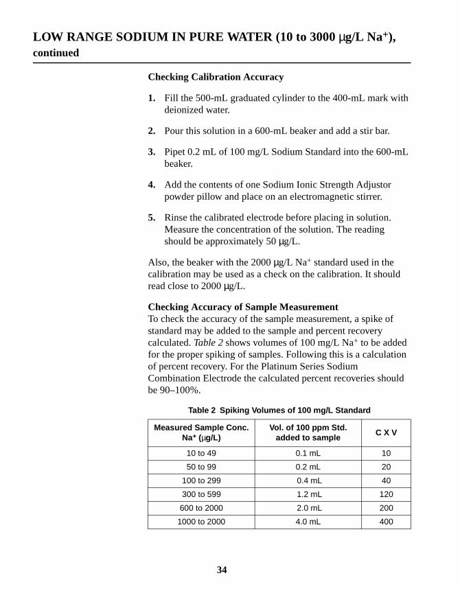
Checking Accuracy of Sample MeasurementTo check the accuracy of the sample measurement, a spike ofstandard may be added to the sample and percent recoverycalculated.Table 2shows volumes of 100 mg/L Na+ to be addedfor the proper spiking of samples. Following this is a calculatioof percent recovery. For the Platinum Series SodiumCombination Electrode the calculated percent recoveries shoube 90–100%.
Table 2 Spiking Volumes of 100 mg/L Standard
Measured Sample Conc.Na+ (µg/L)
Vol. of 100 ppm Std.added to sample
C X V
10 to 49 0.1 mL 10
50 to 99 0.2 mL 20
100 to 299 0.4 mL 40
300 to 599 1.2 mL 120
600 to 2000 2.0 mL 200
1000 to 2000 4.0 mL 400
34

LOW RANGE SODIUM IN PURE WATER (10 to 3000 µg/L Na+),continued
Percent RecoveryCalculate the percent recovery using the formulas below:
M = Calculated mass of sodium present in the sample after the spike (inmicrograms)
S = Sample reading (in mg/L Na+)
C = Concentration of standard used to spike in mg/L
V = Volume of standard used in spike in mL
E = Expected concentration reading after addition of spike
A = Actual concentration reading after adding spike
R = Percent recovery (should be 90–100%)
*Use the numbers fromTable 2.
Method Performance
PrecisionIn a single lab using a standard solution of 25µg/L and twoelectrodes with a singlesension4, a single operator obtained astandard deviation of 1.83 mg/L Na+. Each electrode was exposedto seven test solutions with no rinsing in between and with adefault stability of 0.1 mV/min.
InterferencesThe Sodium ISA is formulated to remove most interferences.Silver is a major interference.
M S 400× C V×( )*+=
EM
400 V+*
----------------------=
RAE---- 100%×=
35

LOW RANGE SODIUM IN PURE WATER (10 to 3000 µg/L Na+),continued
69-025-693972-5
20-1125-005-0080-5281-490-0156-96-00-55
00-0100-02
5-0172-5
63-0060-4160-42
REQUIRED REAGENTSDescription Unit Cat. NoPotassium Chloride Reference Electrolyte Gel Cartridge ................. 3/pkg ................ 254Sodium Ionic Strength Adjustor Powder Pillows .......................... 100/pkg ................ 4451Sodium Standard Solutions 100 mg/L as Na+ .............................. 1000 mL ................ 23181-5Sodium Standard Solutions 1000 mg/L as Na+ .............................. 500 mL ................ 14749-4Water, deionized..................................................................................... 4 L .................... 26
REQUIRED APPARATUSBottle, wash, 500 mL........................................................................................................6Combination Sodium Electrode, Platinum Series, BNC connector.............................. 519sension™4 Laboratory pH/ISE Meter ........................................................................ 5177Beaker, 600 mL, polypropylene...................................................................................... 10Cylinder, graduated, 500 mL, polypropylene ................................................................. 10Pipet, TenSette®, 0.1 to 1.0 mL .................................................................................... 1970Pipet Tips, for TenSette Pipet .......................................................... 50/pkg ................ 218Stir bar, 22.2 x 4.8 mm (7/8 x 3/16”)............................................................................... 45315Stir bar, 50.8 x 7.9 mm (11/8 x 3/10”)............................................................................ 20953Select one based on available voltage:
Stirrer, electromagnetic, 115 V, with stand and stir bar............................................. 453Stirrer, electromagnetic, 230 V, with stand and stir bar............................................. 453
OPTIONAL REAGENTSSodium Ionic Strength Adjustor (ISA), powder ................................454 g ................ 4451Water, deionized..................................................................................... 4 L .................... 26
OPTIONAL APPARATUSWater Bath, circulating ................................................................................................. 261Flask, volumetric, poly, 50 mL ..................................................................................... 140Flask, volumetric, poly, 100 mL ................................................................................... 140
36

SECTION 3 ANALYTICAL METHODS (mV meters)
37

38

he
d
n
.
DIRECT MEASUREMENT METHOD BY GRAPHING
Most modern pH/mV/ISE meters, including the Hachsension™2andsension4, allow the user to perform calibrations for thespecies and concentration range of interest. Once calibrated, tmeter will give a direct reading of the concentration for thatspecies. Unlike many meters, which are limited to linearcalibrations, thesension2 andsension4 meters can cover alarger concentration range that has both linear and non-linearelectrode response regions. Thesesension meters will thenaccurately calculate the concentration from the electrodepotential and display the concentration directly in user-selecteunits such as ppm, mg/L, M, etc.
When the user only has access to a pH/mV meter, the user castill obtain results with the use of semi-log graph paper, plottingconcentration (on the Y log axis) vs. potential (in mV, on the Xaxis). Procedures for graphing these data are described below
Examples of calibration curves are shown inFigure 3andFigure 4,below.
Figure 3 Typical Calibration Curve
39

DIRECT MEASUREMENT METHOD BY GRAPHING, continued
s)
s on
Figure 4 Low Level Calibration Curve
Required Apparatus and Solution for Direct Measurement Method
• Combination Sodium Electrode
• mV or mV/pH meter
• Magnetic stirrer and stir bars
• Plastic beakers, 50- or 100-mL
• Sodium Standard solutions, to cover range of interest
• Sodium ISA powder pillows, or Sodium ISA powder
• Ammonium Chloride Reference Electrolyte Gel Cartridge(if not using a Hach meter with built-in dispenser)
• Semilogarithmic Graph paper, two to five cycles(if not using an ISE meter capable of nonlinear calibration
Preparing Standards for Direct Measurement MethodThe concentration and number of standards to prepare dependthe sample concentrations. If the samples all have similar Na+
concentrations and are in the linear region of the probe (above1 mg/L Na+ or above 10-4 M), use a short direct method of twostandards (one or two powers of ten, or decades, apart in
40

DIRECT MEASUREMENT METHOD BY GRAPHING, continued
r a
tionm,
,
/L,
concentration) that bracket the expected sodium level. To covewider range of sodium concentrations, or to go below 1 mg/L(10-4 M), use multiple standards. SeeFigure 3 and Figure 4.Standard solutions can be purchased or prepared by serial diluof a concentrated sodium solution. Hach standards of 1000 pp100 ppm, and 0.1 M are available; seeReplacement Parts.
To prepare your own standards:
1. Measure 100 mL of the concentrated standard (e.g.,1000 mg/L Na+) into a 1-liter volumetric flask.
2. Fill to the mark with deionized water. Mix. This is a tenfolddilution of the original (e.g., 100 mg/L). Pour the solutioninto a 1-liter plastic container to store. Label the container.
3. Repeat the dilution using the first tenfold dilution (e.g., 100mg/L) to prepare another tenfold dilution (e.g., 10 mg/L).
4. Repeat, diluting each dilution, to cover the lowest expectedlevel (e.g., 0.01 mg/L Na+ or 10-6 M).
Notes
• A 100-mg/L sodium standard solution can be prepared byadding 0.2542 g sodium chloride (analytical reagent gradeoven-dried at l40 °C) to a 1000-mL volumetric flask anddiluting to the mark with deionized water.
• The serial dilutions also could be done from a 0.l–Mstandard, producing 10-2 M, 10-3 M, 10-4 M, and so forth.
• Sodium concentrations can be expressed in units of molesor mg/L of sodium. For example, 2300 mg/L Na+ (sodium) isequivalent to 10-1moles/L (M).
41

DIRECT MEASUREMENT METHOD BY GRAPHING, continued
Preparing a Calibration Curve
1. Measure 25 mL of astandard solution in agraduated cylinder andpour into a 50- or100-mL beaker.
Note: Select standardscovering the range ofinterest. In the linearresponse region of theelectrode, or to cover awide concentration range,one standard per decadeis usually used. Formeasurements in thenonlinear range, usestandards which bracketthe expected range. Themore points used, thebetter the accuracy.
2. Add the contents ofone Sodium ISA powderpillow, or add 0.4 g ofSodium ISA powder.
3. Add a magnetic stirbar, place the beaker ona magnetic stirrer andbegin stirring at amoderate rate. Allowmost of the powder todissolve.
4. Place the electrodein the standard.
5. When a steadyreading is obtained,record the potential.
6. Prepare the nextstandard solution as insteps 1and2.
7. Remove theelectrode from theprevious solution, rinsewith deionized waterand blot dry with a papertowel.
8. Immerse theelectrode in thenew solution.
42

DIRECT MEASUREMENT METHOD BY GRAPHING, continued
9. Record thepotential when thereading is stable.
10. Repeat steps 1–9for all standards to beused for the calibrationcurve.
11. Plot the potentialsvs. sodiumconcentrations onsemilogarithmic graphpaper. Concentrationgoes on the log axis andmay be plotted as mg/L(ppm), moles/L, pNa+,or any convenientconcentration unit.Potentials are plottedon the linear axis; seeFigure 5on page45.
12. Draw a best-fit linethrough the points. Withconcentrations above1 mg/L (7x10⁻⁵ M) thereshould be a straight linewith a slope of58 ±3 mV/decade(at 25 °C).
Note: The best-fit line alsocan be determined bylinear regression analysis,an option on manycalculators and the HachpH/ISE Meter. Theregression analysisprovides a correlationcoefficient and the slopeof the line. With these twofactors, sampleconcentrations can becalculated from themeasured potentials.
Repeat Steps1–9for all Standards
43

DIRECT MEASUREMENT METHOD BY GRAPHING, continued
Procedure
1. Measure 25 mL ofsample with a graduatedcylinder. Pour it into a50- or 100-mL beaker.
2. Add the contents ofone sodium ISA powderpillow or 0.4 g of ISApowder.
3. Add a magnetic stirbar, place the beaker ona magnetic stirrer andbegin stirring at amoderate rate.
4. Remove theelectrode from theprevious solution, rinsewith deionized water, ora portion of the nextsample, and blot drywith a paper towel.
5. Place the electrodein the sample. Recordthe potential when astable reading isobtained.
6. Determine thesodium concentrationfrom the calibrationcurve. See theexample below.
44

DIRECT MEASUREMENT METHOD BY GRAPHING, continued
gat
o
Example:A water sample was measured with the sodium electrode usinthe above procedure. The electrode potential was 100 mV. Whis the sodium concentration of the sample?
a. Locate the sample potential on the linear axis.
b. Draw a horizontal line from the potential on the linearaxis to the calibration curve.
c. From that point on the curve, draw a vertical line down tthe concentration logarithmic axis.
d. Read the point on the logarithmic axis as the sampleconcentration.
Figure 5 is an example of a calibration curve. The electrodepotential is located on the linear axis (step a) 108 mV. Ahorizontal line is drawn to the calibration curve (step b). Avertical line is drawn down to the logarithmic axis (step c). Thesample concentration is 15 mg/L sodium (step d).
Figure 5 Linear Calibration Curve
45

DIRECT MEASUREMENT METHOD BY GRAPHING, continued
8-02-69
81-5349-4972-56
80-4120-1125-0081-400-00-00
00-0100-02062-00
5-01
81-400-0156-96907-00638-00
REQUIRED REAGENTSDescription Unit Cat No.Ammonium Chloride Reference Electrolyte Gel Cartridge .............. 2/pkg ................ 2595Sodium Ionic Strength Adjustor (ISA), powder pillows ............... 100/pkg ................ 44515Sodium Standard Solutions
100 mg/L ................................................................................... 1000 mL ................ 2311000 mg/L ................................................................................... 500 mL ................ 147
Water, deionized.................................................................................. 4.0 L .................... 2
REQUIRED APPARATUSBeaker, 50 mL, polypropylene............................................................. each .................. 10Bottle, wash, 500 mL........................................................................................................6Combination Sodium Electrode, Platinum Series, BNC ..................... each ................ 519Cylinder, graduated, 25 mL, poly ........................................................ each .................. 10sension™1 Portable pH/mV Meter............................................................................. 5170Stir Bar, 22.2 x 4.8 cm (7/8 x 3/16”) ............................................................................... 45315Select one based on available voltage:
Stirrer, electromagnetic, 115 V, with stand and stir bar............................................. 453Stirrer, electromagnetic, 230 V, with stand and stir bar............................................. 453
Semi-log Graph Paper, 2 cycle ..................................................................................... 23
OPTIONAL REAGENTSSodium Ionic Strength Adjustor, bulk powder ...................................454 g ................ 4451
OPTIONAL APPARATUSCylinder, graduated, 25 mL, poly ........................................................ each .................. 10Pipet, TenSette®, 0.1 to 1. 0 mL ................................................................................... 1970Pipet Tips, for 19700-01 TenSette Pipet .......................................... 50/pkg ................ 218Scoop, measuring, 0.5 gram..............................................................................................Scoop, measuring, 0.2 grams............................................................................................
46

iested
LINEAR CALIBRATION WITH TWO STANDARDS
Linear calibration with two standards is a frequently usedcalibration method for direct measurement. The two-pointcalibration may be quickly and easily repeated during each serof measurements. The two standards are chosen in the expecconcentration range of the samples. They often differ inconcentration by one decade.
Note: The two-point calibration should be used only in the linear region.See Measuring Hints.
1. Measure 25 mL ofstandard 1. Pour into abeaker. Add one powderpillow or 0.4 g ofSodium ISA powder.
2. Stir. Place theelectrode into thesolution. Record thepotential when itstabilizes.
3. Rinse and blot theelectrode dry with apaper towel and repeatsteps 1and2 withstandard 2.
4. Calculate thecalibration slope usingequation 1 below.
5. Determine thesample concentration bymeasuring 25 mL ofsample into a beaker andadding one powderpillow or 0.4 g ofSodium ISA powder.
6. Rinse and blot theelectrode dry with apaper towel. Place theelectrode into thestirring sample.
7. Dispense electrolyteif necessary. Measurethe potential.
8. Calculate the sampleconcentration usingequation 2 below.Replace the electrolytecartridge cap when thecartridge is removedfrom the electrode.
47

LINEAR CALIBRATION WITH TWO STANDARDS, continued
Equation 1
Where:
S = slope in mV/decade
E1 and E2 = potentials of the standards
C1 and C2 = the sodium concentrations of standards 1 and 2
Equation 2
Where:
Ex = sample potential
E1 = standard potential
Cx = sample concentration
C1 = standard concentration
S = the electrode slope
Example
Standard 1 (C1) = 10.0 mg/L and its potential (E1) = 113.2 mV.
The slope is 58.1 mV/decade.
The sample potential (Ex) = 136.9 mV
∆E = 136.9 – 113.2 = 23.7 mV
Cx = 10 mg/Lx 1023.7/58.1= 25.6 mg/L
SE1 E2–
log C1 log C2–---------------------------------------=
Cx C1 10 E∆ S⁄×=
E∆ Ex E1–=
48

LINEAR CALIBRATION WITH TWO STANDARDS, continued
the
e
8-025-69
81-5349-4972-5
80-4120-1125-0081-400-00-00
00-0100-02
5-01
0-0156-96907-00638-00
Periodically remeasure the standard and compare it with thecalibration value. If the potential of the standard has changed,offset potential has changed and a new calibration shouldbe done.
If sample temperature and electrode slope are reproducible, thone-standard calibration may be used more often. Thetwo-standard calibration is required when temperatures vary.
REQUIRED REAGENTSDescription Unit Cat No.Ammonium Chloride Reference Electrolyte Gel Cartridge...............2/pkg.................2595Sodium Ionic Strength Adjustor (ISA), powder pillows................ 100/pkg.................4451Sodium Standard Solutions
100 mg/L....................................................................................1000 mL.................2311000 mg/L....................................................................................500 mL.................147
Water, deionized ..................................................................................4.0 L.....................26
REQUIRED APPARATUSBeaker, 50 mL, polypropylene .............................................................each...................10Bottle, wash, 500 mL ........................................................................................................6Combination Sodium Electrode, Platinum Series, BNC......................each.................519Cylinder, graduated, 25 mL, poly.........................................................each...................10sension™1 Portable pH/mV Meter .............................................................................5170Stir Bar, 22.2 x 4.8 cm (7/8 x 3/16”) ................................................................................45315Select one based on available voltage:
Stirrer, electromagnetic, 115 V, with stand and stir bar .............................................453Stirrer, electromagnetic, 230 V, with stand and stir bar .............................................453
OPTIONAL REAGENTSSodium Ionic Strength Adjustor, bulk powder................................... 454 g.................4451
OPTIONAL APPARATUSPipet, TenSette®, 0.1 to 1. 0 mL....................................................................................1970Pipet Tips, for 19700-01 TenSette Pipet ..........................................50/pkg.................218Scoop, measuring, 0.5 gram..............................................................................................Scoop, measuring, 0.2 grams ............................................................................................
49

50
ts to
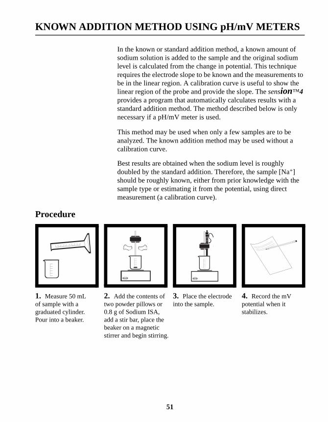
KNOWN ADDITION METHOD USING pH/mV METERS
In the known or standard addition method, a known amount ofsodium solution is added to the sample and the original sodiumlevel is calculated from the change in potential. This techniquerequires the electrode slope to be known and the measuremenbe in the linear region. A calibration curve is useful to show thelinear region of the probe and provide the slope. Thesension™4provides a program that automatically calculates results with astandard addition method. The method described below is onlynecessary if a pH/mV meter is used.
This method may be used when only a few samples are to beanalyzed. The known addition method may be used without acalibration curve.
Best results are obtained when the sodium level is roughlydoubled by the standard addition. Therefore, the sample [Na+]should be roughly known, either from prior knowledge with thesample type or estimating it from the potential, using directmeasurement (a calibration curve).
Procedure
1. Measure 50 mLof sample with agraduated cylinder.Pour into a beaker.
2. Add the contents oftwo powder pillows or0.8 g of Sodium ISA,add a stir bar, place thebeaker on a magneticstirrer and begin stirring.
3. Place the electrodeinto the sample.
4. Record the mVpotential when itstabilizes.
51

KNOWN ADDITION METHOD USING pH/mV METERS, continued
5. Use a calibrationcurve (seeFigure 5onpage45) to estimate thesample sodiumconcentration fromthe potential.
6. Using equation 1 andexample 1, below,calculate the volume ofsodium standard neededto roughly double the[Na+].
7. Add the calculatedvolume of standard intothe stirring sample.
Note: Using fairlyconcentrated standardswill change the totalsolution volume lessbecause smaller volumesare added. Additionvolumes of 1% or less ofthe sample volume areassumed in the calculationbelow.
8. Record the potentialwhen it stabilizes.Calculate the sampleconcentration usingequations 2 and 3 andexample 2, below.
52

KNOWN ADDITION METHOD USING pH/mV METERS, continued
en
Equation 1:
Where V = volume and C = concentration
Example 1How many mL of a 100-mg/L sodium standard are needed whthe electrode potential of a 50-mL sample suggests theapproximate sodium concentration is 1 mg/L?
Add 0.5 mL of sodium standard to the sample.
Equations 2 and 3:
Where:
E1 and E2 = the first and second potentials measured
S = the electrode slope (a positive value)
CNa+ = the sodium concentration in the sample
Vs dardtanCsample Vsample×
Cs dardtan-------------------------------------------------=
Vs dardtan1 50×
100----------------- 0.50mL==
CNa+Vs dardtan Cs dardtan×
Vsample 10 E∆ S⁄ 1–( )×----------------------------------------------------------------=
E∆ E2 E1–=
53

KNOWN ADDITION METHOD USING pH/mV METERS, continued
.
Example 2The sample potential is 87.6 mV. Upon adding 0.20 mL of2300 mg/L (0.1 M) standard the potential goes to 110.6 mV.
∆E = 110.6– 87.6 = 23.0 mV
Vstandard = 0.20 mL; Cstandard = 2300 mg/L
Vsample = 50 mL
Slope S was experimentally determined to be 56.6 mV/decade
CNa+ = (0.20 x 2300)÷ [50 x (1023.0/56.6 - 1)]
CNa+ = 5.90 mg/L
54

KNOWN ADDITION METHOD USING pH/mV METERS, continued
8-025-69
81-5349-4972-56
80-4120-1125-0081-400-005-000-00-00
00-0100-02
5-01
81-400-0156-96907-00638-00
REQUIRED REAGENTSDescription Unit Cat No.Ammonium Chloride Reference Electrolyte Gel Cartridge...............2/pkg.................2595Sodium Ionic Strength Adjustor (ISA), powder pillows................ 100/pkg.................4451Sodium Standard Solutions
100 mg/L......................................................................................500 mL.................2311000 mg/L....................................................................................500 mL.................147
Water, deionized ................................................................................3.78 L.....................2
REQUIRED APPARATUSBeaker, 50 mL, polypropylene .............................................................each...................10Bottle, wash, 500 mL ........................................................................................................6Combination Sodium Electrode, Platinum Series, BNC connector .....each.................519Cylinder, graduated, 25 mL, poly.........................................................each...................10sension™1 Portable pH Meter ....................................................................................5170sension™2 Portable pH/ISE Meter .............................................................................5172sension™3 Laboratory pH Meter ................................................................................5175Stir Bar, 22.2 x 4.8 cm (7/8 x 3/16”) ................................................................................45315Select one based on available voltage:
Stirrer, electromagnetic, 115 V, with stand and stir bar .............................................453Stirrer, electromagnetic, 230 V, with stand and stir bar .............................................453
OPTIONAL REAGENTSSodium Ionic Strength Adjustor, bulk powder................................... 454 g.................4451
OPTIONAL APPARATUSCylinder, graduated, 25 mL, poly.........................................................each...................10Pipet, TenSette®, 0.1 to 1. 0 mL....................................................................................1970Pipet Tips, for 19700-01 TenSette Pipet ..........................................50/pkg.................218Scoop, measuring, 0.5 gram..............................................................................................Scoop, measuring, 0.2 grams ............................................................................................
55

56

a
r
onele
gly
ed.lyte
llfor
he
SECTION 4 ELECTRODE MAINTENANCE
The Platinum Series Combination Sodium electrode containssensing bulb and a liquid reference junction optimized forperformance in saline solutions. This sensitive instrument hasbeen designed to give trouble-free use, but requires carefulhandling to extend longevity. This section explains methods focleaning and storing the Platinum Series CombinationSodium electrode.
4.1 Storing the Electrode:Proper electrode storage requires different approaches basedhow long the electrode will be stored, how quickly the electrodneeds to be brought to working condition, and the type of sampbeing measured. Storage affects the ammonium chlorideelectrolyte gel, the Ag/AgCl reference element, and the sensinbulb. Do not allow the electrode to dry out; this may permanentreduce performance.
Do not leave the electrode in solutions with low sodiumconcentrations for extended periods (especially deionized andultrapure water). This can shorten electrode life.
Intermittent storage—Store the electrode in either SodiumStorage Solution (1 M sodium chloride), or a sodium standardsolution in the range of samples being measured with ISA addBefore measuring a new sample, refresh the reference electrogel by clicking the dispenser several times. Carefully rinse theelectrode to prevent contaminating the sample.
Overnight storage and longer-term storage—When not usedfor up to one week, store the electrode in a small volume ofSodium Storage Solution (1 M sodium chloride), or a sodiumstandard solution with ISA added. Fill the electrode cap half fuwith standard solution and insert the electrode end into the captemporary storage or for field transportation. In the laboratory,store the electrode in a beaker of standard. Prior to use, click telectrolyte gel dispenser. A dilute gel/storage solution willinitially be ejected from this tube. The reference gel of thickerviscosity will follow. Eliminating the dilute gel/storage solutionwill guarantee continuity of the reference junction with thesample. Blot the reference junction with a tissue to clearly seethat the electrolyte gel, not gel diluted with storage solution,is emerging.
57

SECTION 4, continued
in
me
t
d.e.
Shelf Storage—For very long-term storage, store the electrodesodium electrode storage solution. If storing longer than twoweeks, replace the electrolyte cartridge before using and reprithe reference electrode.
4.2 Cleaning the ElectrodeA contaminated bulb or fouled electrode may cause slowresponse times. Clean the electrode only after conducting thesteps described inSECTION 6 TROUBLESHOOTINGor whenthe electrode is known to be dirty. According to the instructionsbelow, clean the electrode according to the type of contaminanpresent:
General contamination—Immerse the electrode tip in0.1 N Hydrochloric Acid followed by immersion in 0.1 N SodiumHydroxide and again in 0.1 N Hydrochloric Acid, each for a2-minute period. Rinse with deionized water and soak indeionized water for at least 15 minutes.
Oils and fats—Immerse the electrode tip in a detergent solutionsuch as Alconox™. Use a soft brush or ultrasonic bath ifnecessary.Avoid scratching the bulb.
Organic films—Use an appropriate solvent, such as methanolor acetone.
After cleaning, refresh reference half-cells by pumping freshelectrolyte through them. If the electrode has been sitting in asample for several weeks, the reference gel will become diluteIn this case, discard the cartridge and replace it with a fresh on
If these steps fail to improve electrode response, replacethe electrode.
58

e
ithl
uit
SECTION 5 ELECTRODE THEORY
5.1 Theory of OperationThe glass sensing membrane in the probe is in contact with aninternal filling solution and the external sample solution. Aconstant potential is maintained inside the glass bulb due to thfixed ion concentrations of the internal filling. The outer,hydrated surface of the glass bulb can exchange sodium ions wthe sample solution, setting up a potential which is proportionato the concentration of sodium ions in solution.
A reference electrode is required to complete the electrical circthrough the pH/mV meter, and establish a stable, reproduciblepotential. In the complete electrochemical cell consisting of thereference and indicator half cells, only the potential across thesensing membrane should vary.
The measured cell potential is related to the sodium ionconcentration by the Nernst Equation:
E = E° - S log aNa
Where:
E = measured cell potential in millivolts
E° = “standard” electrode potential
S = 2.3RT/F, slope factor dependent on temperature
aNa = activity of sodium ions
Typical electrode response to sodium ions from 10-1 M(2300 ppm) to 10-6 M (0.023 ppm) is shown inFigure 6.
59

SECTION 5, continued
fe
a
s
r
forrees°C
Figure 6 Low Level Calibration Curve
5.2 Temperature EffectsThe formula for potential given above indicates that the slope othe response, and therefore the actual potential, depends on thtemperature. Normally all standards and samples should bemeasured at the same temperature (within 1 °C).
The change in the slope of the electrode response can betemperature corrected if manual calibration curves at differenttemperatures have been made. Some pH/mV/ion meters haveprovision for entering the “isopotential” point (if known) for theelectrode. This is the theoretical point at which all temperaturegive the same potential. However, as the electrode standardpotential and the slope change with temperature, correcting fojust the slope is not accurate. The best method is to have aconstant temperature for all measurements.
Very accurate work may require the use of a temperature bathstandards and samples. Maintain the temperature several degabove the ambient temperature. With the sodium electrode, a 1change in temperature causes 0.3% change in slope.
60

SECTION 5, continued
tesm
ertir
to
ee.
n.o
5.3 Response TimeThe response of the sodium electrode may take from 2–4 minuto reach 99% of its total response for decade changes in sodiuconcentration. Response times with smaller concentrationchanges generally will be longer and can be minimized by propstirring and conditioning. Experiment to determine the proper srate. Generally, conditioning the electrode in sodium standards(containing Sodium and Potassium ISA) near the concentrationbe measured provides fastest equilibrium.Figure 7shows theelectrode response for various changes in [Na+]. If the electrodresponse is slower than usual, try cleaning the glass membranSeeSection 4.2 Cleaning the Electrode.
Figure 7 Calibration Chart Recording
5.4 Ionic Strength EffectsThe probe actually senses sodium ion activity, not concentratioThe activity (the thermodynamic “force” of the ions) is related tthe concentration:
aNa = CNa X f
Where:
aNa = activity of sodium ions
CNa = concentration of sodium ions
f = activity coefficient
2 MINUTES
TIME
200
150
100
50
0
-50
ELE
CT
RO
DE
PO
TE
NT
IAL
(mV
)
10-1
10-2
10-3
10-4
10-6
10-5
SO
DIU
M C
ON
CE
NT
RA
TIO
N (
M)
61

SECTION 5, continued
h.
nd
ee
ards
umtht-
The activity coefficient varies with ionic strength (a measure oftotal number of ions in the solution). Because the sodiumconcentration is usually what is measured, control of the ionicstrength is a part of most procedures. Control the ionic strengtby having all standards and samples at the same ionic strengthThe activity coefficients are then equal for all measurements, aa calibration curve of concentration vs. potential (mV) can beplotted and used instead of activity vs. potential.
Raising the ionic strength to a high value by ionic strengthadjustors is a common method of insuring that all samples havthe same ionic strength. This high value minimizes the influencof sample ionic strength variation on sample measurement.Sodium ionic strength adjustors, which are concentrated saltsolutions containing a base to raise the pH, are added to standand samples before measurement.
The most commonly used ionic strength adjustor for sodiummeasurements is made from ammonium chloride and ammonihydroxide. Hach offers an improved Sodium/Potassium ISA wia lower blank level, in convenient powder form, available in unidose powder pillows or bulk powder.
If a liquid ISA is preferred, the conventional ammonium ionbased solution can be prepared as follows:
a. Dissolve 20 g analytical reagent-grade ammoniumchloride in 50 mL of deionized water.
b. Add 27 mL of concentrated ammonium hydroxide.
c. Dilute to 100 mL with deionized water. This ISA is usedby adding 1 mL ISA per 50 mL of sample or standard.
62

SECTION 5, continued
um,ionto
e
ed
l
nfty,
to
3
5.5 InterferencesThe sodium glass membrane responds to ions other than sodiso interferences exist. Typically, electrode response to anotherincreases the potential, causing a positive error. The responseother ions can be semi-quantitatively determined through theNicholsky equation, an extended Nernst equation:
E = E° + (RT/zF) ln [aNa + KNaX X aX]
Where:
aX = the activity of the interfering ion
KNaX = the selectivity coefficient for the interfering ion relative to sodium.
The value of the selectivity coefficient should be small to reducthe interference. A major advantage of the Hach Sodiumelectrode is the reduced interferences from other ions comparto the standard sodium selective glass (NAS 11–18). If theelectrode is exposed to high levels of interferences, soaking inSodium Electrode Storage Solution or 1 M sodium chloride wilhelp remove the adsorbed ions from the glass membrane.
The major interferences are silver and hydrogen ions. Hydrogeion concentration is reduced by the ISA, which raises the pH. Ithe samples are extremely acidic, or have a high buffer capacicheck that the sample pH is above 9 after adding ISA. Ifnecessary, ammonium hydroxide can be added to the samplesraise the pH. The electrode potential will not be affected if the[H+] is about 1000-fold less than the [Na+], or the pH should beto 4 units higher than the pNa.
Selectivity coefficients at 10-5 M Na+ (mixed solutions) are:
KNa+ K+⁄
5 10 5–×=
KNa+ NH4
+⁄2 10 5–×=
KNa+ Ag+⁄
10≥
63

64

ted
nt
he
SECTION 6 TROUBLESHOOTING
6.1 General TroubleshootingThe most important principle in troubleshooting is isolating thecomponents of the system and checking each in turn. Thecomponents of the system are the 1) Meter, 2) Electrode,3) Standard, 4) Sample, and 5) Technique. Also refer toTable 3,Troubleshooting Checklist.
MeterThe meter is the easiest component to eliminate as a possiblecause of error. Hach meters have an instrument checkoutprocedure in the instruction manual and a shorting strap forconvenience in troubleshooting. Consult the manual for compleinstructions and verify that the instrument operates as indicateand is stable in all steps.
Electrode
1. Rinse the electrode thoroughly with demineralized water.
2. Check the electrode operation (slope). If the electrode failsthis procedure, re-soak the sodium electrode as directed inSection Section 1.3.2 Preparing the Reference Half Cell.
3. Repeat the slope check instep 2.
4. If the stability and slope check out properly, but measuremeproblems persist, the sample may contain interferences orcomplexing agents, or the technique may be in error. See tStandard, Sample, and Techniquesections, below.
5. Before replacing a “faulty” electrode, or if another electrodeis not available for test purposes, review the instructionmanual and be sure to:
• Clean the electrode thoroughly.
• Prepare the electrode properly.
• Use proper filling solutions, ISA, and standards.
• Measure correctly.
• Review the Troubleshooting Checklist.
65

SECTION 6, continued
f
re
le,ces
.If anlve
on
ion
StandardThe quality of results depends greatly upon the quality of thestandards. ALWAYS prepare fresh standards when problemsarise—it could save hours of frustrating troubleshooting! Errorsmay result from contamination of prepared standards, quality odilution, deionized water, or a numerical error in calculating theconcentrations. Do not confuse sodium and sodiumchloride standards.
The best method for preparing standards is serial dilution. Aninitial standard is diluted, using volumetric glassware, to prepaa second standard solution. The second is similarly diluted toprepare a third standard, and so on, until the desired range ofstandards has been prepared. Hach has a variety of sodiumstandards available.
SampleIf the electrodes work properly in standards but not in the samplook for possible interferences, complexing agents, or substanthat could affect response or physically damage the sensingelectrode or the reference electrode. If possible, determine thecomposition of the samples and check for problems. SeeSectionSection 5.5 Interferences.
TechniqueCheck the method of analysis for compatibility with your sampleDirect measurement may not always be the method of choice.large amount of complexing agents are present, known additiomay be best. If the sample is viscous, analate addition may sothe problem.
If working at low levels, follow the low-level measurementtechnique. Also, be sure that the expected sodium concentratiis within the electrode’s limits of detection.
If problems persist, review operational procedures and instructmanuals to be sure that proper technique has been followed.RereadSection 1.6 Measuring Hintsand the procedures section.
66
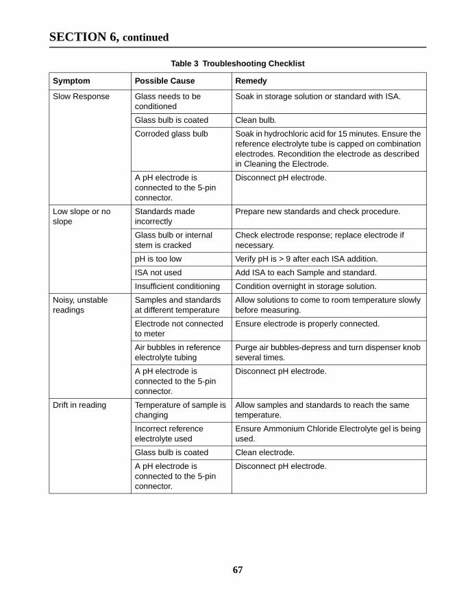
SECTION 6, continued
Table 3 Troubleshooting Checklist
Symptom Possible Cause Remedy
Slow Response Glass needs to beconditioned
Soak in storage solution or standard with ISA.
Glass bulb is coated Clean bulb.
Corroded glass bulb Soak in hydrochloric acid for 15 minutes. Ensure thereference electrolyte tube is capped on combinationelectrodes. Recondition the electrode as describedin Cleaning the Electrode.
A pH electrode isconnected to the 5-pinconnector.
Disconnect pH electrode.
Low slope or noslope
Standards madeincorrectly
Prepare new standards and check procedure.
Glass bulb or internalstem is cracked
Check electrode response; replace electrode ifnecessary.
pH is too low Verify pH is > 9 after each ISA addition.
ISA not used Add ISA to each Sample and standard.
Insufficient conditioning Condition overnight in storage solution.
Noisy, unstablereadings
Samples and standardsat different temperature
Allow solutions to come to room temperature slowlybefore measuring.
Electrode not connectedto meter
Ensure electrode is properly connected.
Air bubbles in referenceelectrolyte tubing
Purge air bubbles-depress and turn dispenser knobseveral times.
A pH electrode isconnected to the 5-pinconnector.
Disconnect pH electrode.
Drift in reading Temperature of sample ischanging
Allow samples and standards to reach the sametemperature.
Incorrect referenceelectrolyte used
Ensure Ammonium Chloride Electrolyte gel is beingused.
Glass bulb is coated Clean electrode.
A pH electrode isconnected to the 5-pinconnector.
Disconnect pH electrode.
67

68

he
de
en
.
is
s
ELECTRODE SERVICE REQUEST QUESTIONNAIRE
1. What is the catalog number of the electrode?
2. What model of meter is the electrode being used with?
3. What is the complete lot code of the electrode (located on telectrode cable)?
4. What is the date the electrode was purchased?
5. How long has the electrode been in use?
6. What types of samples are being tested?
7. What is the temperature of the samples being tested?
8. How often is electrode being used?
9. How is the electrode being stored between uses?
10. What are the millivolt readings in standards that are a decaapart for ISE electrodes?
11. What is the slope of electrode during a typical calibration?
12. If the electrode is new, has it been conditioned according tothe manual?
13. If the electrode has been in use, what maintenance has beperformed as suggested in the manual?
14. Describe the suspected problem or failure of the electrode
15. When calling for telephone support it will be helpful to haveyour meter, electrode, and buffers/standards, along with thcompleted questionnaire, near the phone before calling.
16. Did you use ISA in all samples and standards?
17. Did you use the low range method for drinking water samplebelow 3 mg/L sodium?
18. Is the sample above 1.0 mg/L sodium (the linear range ofthe electrode)?
69

70

.0.
ed
n
.
d
GLOSSARY
Acid — a chemical compound that contributes hydrogen ions(H+) to an aqueous solution or causes the pH to be less than 7
Acidic — A solution or system with a pH less than 7.0
Activity — The measure of work performed by an ion as itmoves through a system. The activity is dependent upon theconcentration of all ions in the system and the charge associatwith the ion.
Alkali — A solution or system with a pH greater than 7.0
Alkalinity — Capacity of water to accept hydrogen ions (H+).Indicates presence of carbonate (CO3
2-), bicarbonate (HCO3),and hydroxyl (OH-) ions.
Anion — A negatively charged ion (i.e., NO3-, Cl-).
Base —A chemical compound that contributes hydroxide ions(OH-) to an aqueous solution or causes the pH to be greaterthan 7.0
Buffer —1) A compound, mixture of compounds, or solution which, wheadded to a system, changes pH to a specified, known value.
2) The ability of a solution or system to resist change in pH ifeither an acid or a base is added.
Buffering capacity — A measurement of the amount of acid orbase which can be added to a solution before the pH changes
Cation — A positively charged ion (i.e., NH4+, Ca2+).
Conditioning — The process of preparing an electrode for useby soaking the electrode in a solution with a pH and ionicstrength similar to the sample. Conditioning allows the hydratelayer, necessary for accurate measurements, to form.
Decade —Any two standards with a concentration ratio of 10.For example:
Concentration of the higher standardConcentration of the lower standard------------------------------------------------------------------------------------------------- 10=
71

GLOSSARY, continued
e
age
to
or
Dilution factor — A numerical value by which results must bemultiplied in order to obtain the actual value of the sample. Forexample, if 1 mL of sample is diluted to 10 mL, then the resultobtained must be multiplied by 10 to obtain the value for thesample before dilution.
Electrolyte — A solution made of dissolved ions that is used tofacilitate electrical conductance and ionic transport. Thecomposition is usually potassium chloride (KCl), sodium chlorid(NaCl), ammonium chloride (NH4Cl), or ammonium sulfate((NH4)2SO4).
Free-flowing reference junction —The point on the electrodewhere reference gel is freely dispensed without obstruction byfrits or other materials.
Hydrated layer — A layer that forms at the glass/liquidinterface. Chemically similar to the sample being measured(especially in samples of low ionic strength), the formationcharacteristics of this layer depend upon the type of glass, theof the glass, the previous usage history of the glass, thetemperature and ionic strength of the aqueous solution, etc.
Inert — Does not react with other substances.
Ion — An atom, group of atoms or molecule that is electricallycharged as the result of gaining or losing electrons. An ionresulting from the gain of electrons becomes negative (anion),while an ion resulting from the loss of electrons becomespositive (cation).
Ionic strength — A measure of the concentration of any ion insolution, usually expressed in moles per liter.
Occasional use —Infrequent use where the probe is subjectedtest conditions just long enough to obtain a proper reading.
pH — A relative numerical measurement of the acidic, neutral,alkali nature of a solution or system. Mathematically defined asthe negative log of the hydrogen ion concentration.
72

GLOSSARY, continued
is ak
Potential — The capacity of a system to perform work. Whentwo ions of opposite charge are separated by a distance, therepotential developed from the tendency of the ions to come bactogether. Each ion exerts work to come back together. Theamount of work needed by each ion to come back together isthe potential.
Reference junction —The point on the electrode wherereference gel is dispensed.
Routine use —Typical use following regular, frequent routines,but not continuous as with an in-line monitoring process.
Salt — An ionic compound.
73

74

GENERAL INFORMATION
75
At Hach Company, customer service is animportant part of every product we make.
With that in mind, we have compiled thefollowing information for your convenience.

76

HOW TO ORDER
77

REPAIR SERVICE
78

WARRANTY
79