Embed Size (px)
Citation preview

Door lock and transponder override firmware for specific Toyota, Lexus, Scion and Pontiac vehicles. It is compatible with models that use the RX/TX immobilizer lines at key switch and with select PTS models.
Installation Guide
Update Alert: Firmware updates are posted on the web on a regular basis. We recommend that you check for firmware and/or install guide updates prior to installing this product.
Vehicle Application Guide................................................................................................................................................
OEM Remote Starter Detection.......................................................................................................................................
Installation (Wiring Diagrams & Vehicle Wiring Reference Charts)Type 1..............................................................................................................................................................................Type 2..............................................................................................................................................................................Type 2 with T-Harness TLTH1.........................................................................................................................................Type 3..............................................................................................................................................................................Type 3 with T-Harness TLTH1.........................................................................................................................................Type 4..............................................................................................................................................................................Type 5..............................................................................................................................................................................Type 6..............................................................................................................................................................................
ProgrammingModule Programming Type 1 (Key-type vehicles)................................................................................................................................. Types 2 & 3 (PTS-type vehicles)........................................................................................................................ Type 4 (Key-type vehicles without CAN)............................................................................................................ Type 5 (PTS-type vehicles without CAN)........................................................................................................... Type 6 (PTS-type Toyota Prius)..........................................................................................................................Module Reset...................................................................................................................................................................Hard Reset.......................................................................................................................................................................Feature & Option List.......................................................................................................................................................Feature Programming......................................................................................................................................................
LED Diagnostics & Troubleshooting.................................................................................................................................Limited One-Year Consumer Warranty............................................................................................................................
Quick Reference Guide...................................................................................................................................................
02
04
0507081011131618
202121222223232424
252627
Index
® Toyota and Lexus are registered trademarks and property of their respective companies.
- No takeover feature is available for Push-to-Start vehicles.- If there is no immobilizer, the module will not work (that also includes door lock controls).
WARNING
Rev.: 20160106
Platform: DBALL/DBALL2Firmware: TL1
© 2016 Directed. All rights reserved.

Vehicle Application GuidePage 2
The following table lists the vehicles and features which are compatible with this product. The number assigned to each year allows you to determine which installation type should be used for your vehicle.
Note: Keyless and Smart-Key will remain functional during remote start.
Go to the next page to see the Toyota Vehicle Application Guide.
- No takeover feature is available on Push-to-Start vehicles.
- If equipped, the OE remote starter must be removed before installation. See page 4 for more information.
Vehicles
2013
2012
2011
2010
2009
2008
2007
2006
2005
2004
2003
PK
-Im
mobili
zer
Bypass-D
ata
No
Key
Req'd
DL-A
rmF
acto
ryS
ecurity
DL-D
isarm
Facto
ryS
ecurity
DL-D
oor
Lock
Contr
ol
DL-D
oor
Unlo
ck
DL-D
river
Priority
Unlo
ck
DL-H
atc
hG
lass
Rele
ase
DL-T
runk
/H
atc
hR
ele
ase
RS
-Tach
/R
PM
Outp
ut
SS
-Entr
yM
onitoring
ALL
Door
Pin
s
SS
-Entr
yM
onitoring
Driver
Door
Pin
SS
-Entr
yM
onitoring
Hood
Pin
SS
-Entr
yM
onitoring
Tru
nk/H
atc
hP
in
SS
-Facto
ryA
larm
Trigger
Monitoring
ST
-Bra
ke
Sta
tus
(foot
bra
ke)
ST
-E-B
rake
Sta
tus
ST
-Ignitio
nS
tatu
s
Lexus
ES 330 4 4 4 •
ES 350 (Smart Key) 3 3 3 3 3 3 • • • • • • • • • • • • D • • •
GS 300 (Smart Key) 5 •
GS 350 (Smart Key) 5 5 •
GS 430 (Smart Key) 5 5 •
GS 450h (Smart Key) 5 5 •
GS 460 (Smart Key) 5 •
GX 470 4 4 4 4 4 4 4 •
IS 250 (Smart Key) 5 5 5 •
IS 350 (Smart Key) 5 5 5 •
IS F (Smart Key) 5 •
LS 430 4 4 4 •
LS 460 (Smart Key) 5 5 •
LS 600h (Smart Key) 5 •
LX 470 4 4 4 4 4 •
RX 330 4 4 4 •
RX 350 4 4 4 •
RX 400h 4 4 4 •
Pontiac
Vibe 1 1 • • • • • • • • • • • D • • •
Vibe 4 •
Scion
tC 4 4 4 4 4 4 •
xB 1 1 1 • • • • • • • • • • • D • • •
xD 1 1 1 • • • • • • • • • • • D • • •
Legend:
D: Data-to-Data (D2D) only AV: Horn & Lights Controls
•: D2D & Wire-to-Wire (W2W) DL: OE Door Lock & Alarm Controls
PK: Transponder & Immobilizer Override
RS: Remote Start & Engine Controls
SS: Integrated Security & Monitoring
ST: Function/Feature Status
Rev.: 20160106
Platform: DBALL/DBALL2Firmware: TL1
© 2016 Directed. All rights reserved.
Page 3
Vehicle Application Guide
Standard Key G-stamped keys H-stamped keysFor vehicles with G-stamped key, see TL4,TL5 or TL7 firmware. TL1 works only withstandard key.
For vehicles with H-stamped key, see TL10 firmware. TL1 works only with standard key.
Key TypeSome Toyota 2010+ models have different encryption types. Please look at your key blade and identify the markings. A dot “.” means the vehicle is compatible with TL1 firmware. “G” or “H” indicates the vehicle is not compatible with this firmware.
H
Note: Keyless and Smart-Key will remain functional during remote start.
- No takeover feature is available on Push-to-Start vehicles.- If equipped, the OE remote starter must be removed before installation. See page 4 for more information.
Vehicles
2013
2012
2011
2010
2009
2008
2007
2006
2005
2004
2003
PK
-Im
mobili
zer
Bypass-D
ata
No
Key
Req'd
DL-A
rmF
acto
ryS
ecurity
DL-D
isarm
Facto
ryS
ecurity
DL-D
oor
Lock
Contr
ol
DL-D
oor
Unlo
ck
DL-D
river
Priority
Unlo
ck
DL-H
atc
hG
lass
Rele
ase
DL-T
runk
/H
atc
hR
ele
ase
RS
-Tach
/R
PM
Outp
ut
SS
-Entr
yM
onitoring
ALL
Door
Pin
s
SS
-Entr
yM
onitoring
Driver
Door
Pin
SS
-Entr
yM
onitoring
Hood
Pin
SS
-Entr
yM
onitoring
Tru
nk/H
atc
hP
in
SS
-Facto
ryA
larm
Trigger
Monitoring
ST
-Bra
ke
Sta
tus
(foot
bra
ke)
ST
-E-B
rake
Sta
tus
ST
-Ignitio
nS
tatu
s
Toyota
4Runner 4 4 4 4 4 4 4 4 •
Avalon 4 4 4 4 4 4 •
Avalon (Smart Key) 5 5 5 5 5 •
Camry 1 1 1 1 1 • • • • • • • • • • • • D • • •
Camry 4 4 4 4 •
Camry (Smart Key) 3 3 3 3 3 • • • • • • • • • • • • D • • •
Camry Hybrid 3 3 3 3 3 • • • • • • • • • • • • D • • •
Corolla 1 1 • • • • • • • • • • • • D • • •
Corolla 4 4 4 4 •
Corolla (Smart Key) 2 2 2 2 2 • • • • • • • • • • • • D • • •
FJ Cruiser 4 4 4 •
Highlander 1 1 1 • • • • • • • • • • • • D • • •
Highlander 4 4 4 4 •
Highlander (Smart Key) 3 3 3 3 3 3 • • • • • • • • • • • • D • • •
Highlander Hybrid 3 3 3 3 3 3 • • • • • • • • • • • • D • • •
Highlander Hybrid 4 4 •
Land Cruiser 4 4 4 4 4 •
Land Cruiser (Smart Key) 5 5 5 •
Matrix 1 1 • • • • • • • • • • • D • • •
Matrix 4 4 4 4 •
Prius (Smart Key) 6 6 6 6 6 6 •
RAV4 1 1 1 1 1 • • • • • • • • • • • D • • •
RAV4 4 4 •
RAV4 (Smart Key) 2 2 2 2 • • • • • • • • • • • D • • •
Sequoia 4 4 4 •
Sienna 4 4 4 4 4 4 4 •
Solara 4 4 4 4 4 4 •
Tacoma 4 4 4 4 4 4 •
Tundra 4 4 4 4 •
Venza 4 •
Yaris 4 4 4 4 4 4 •
Yaris Sedan 4 4 4 4 4 •
Legend:
D: Data-to-Data (D2D) only AV: Horn & Lights Controls
•: D2D & Wire-to-Wire (W2W) DL: OE Door Lock & Alarm Controls
PK: Transponder & Immobilizer Override
RS: Remote Start & Engine Controls
SS: Integrated Security & Monitoring
ST: Function/Feature Status
Rev.: 20160106
Platform: DBALL/DBALL2Firmware: TL1
© 2016 Directed. All rights reserved.

Rev.: 20160106
Platform: DBALL/DBALL2Firmware: TL1
© 2016 Directed. All rights reserved.
Vehicle OEM Remote Starter & Connector Location
Toyota Camry (key) 2007-2010 Behind Glove Box & Passenger kick panel
Toyota Corolla (key) 2009-2010 Behind Glove Box & Passenger kick panel & Junction Box & Steering column
Toyota Highlander (key) 2007-2010 Behind Glove Box & Steering column
Toyota Matrix (key) 2009-2010 Junction Box & Behind Glove Box & Passenger kick panel
Pontiac Vibe (key) 2009-2010 Behind Glove Box & Junction Box & Passenger kick panel
Scion xB (key) 2008-2010 Behind Glove Box & Passenger kick panel & Junction Box & Steering column
Scion xD (key) 2008-2010 Behind Glove Box & Passenger kick panel & Junction Box & Steering column
Toyota Rav4 (key) 2006-2010 Behind Glove Box & Passenger kick panel & Junction Box & Steering column
Toyota Sequoia (key) 2008-2010 Behind Glove Box & Passenger kick panel & Steering column
Toyota Tundra (key) 2007-2010 Behind GloveBox & Passenger kick panel & Steering column
Toyota Yaris (key) 2006-2010 Behind Glove Box & Junction Box & Steering column
Toyota Corolla (Smart Key) 2009-2013 Behind Glove Box & Passenger kick panel & Junction Box & Steering column
Toyota Rav4 (Smart Key) 2009-2012 Behind Glove Box & Junction Box
Toyota Camry (Smart Key) 2007-2011 Behind Glove Box & Passenger kick panel
Toyota Camry Hybrid (Smart Key) 2007-2011 Behind Glove Box & Passenger kick panel
Toyota Highlander (Smart Key) 2008-2013 Behind Glove Box & Passenger kick panel
Toyota Highlander Hybrid (Smart Key) 2008-2013 Behind Glove Box & Passenger kick panel
OEM Remote Starter Detection
If the Vehicle is Equipped with an OEM Remote Starter
How to Know if the Vehicle is Equipped with an OEM Remote Starter
1- An “ENGINE STARTER” sticker should be on the remote.
2- Remote start the OEM remote starter:Press the remote control’s lock button twice within 2 seconds, then press and hold the lock button for 3 seconds.
The parking lights flash after 3 seconds. The engine starts and the parking lights flash repeatedly for 20 seconds.
ENGINESTARTER
x2 &Press & Holdfor 3 seconds
If the vehicle is equipped with an OEM remote starter, the DBALL LED will start flashing orange to indicate its detection. To skip bypass and use convenience only, press the programming button 5 times.* The reason for this is to allow aftermarket security to be installed while keeping the factory remote starter active. If you wish to use DBALL to control the remote start sequence, the factory remote starter must be disconnected before programming the DBALL as both modules cannot coexist.
Locating the OEM Remote Starter
* The DBALL LED turns ON solid orange for 3 seconds after programming or power up to indicate the bypass is not active. Refer to LED Diagnostics & Troubleshooting section for more information.
Page 4

Page 5
Connect toIgnition Connector
Visit our websitewww.directechs.comfor more information.
(+) Ignition (some vehicles require 2 ignition)
White Connector (at headlight switch)
12345678910
1112131415161720 19
DiagnosticConnector at OBDII
1 8
169
Installation Type 1
[1] (AC) Tach Input
(-) Trunk Status Input
(-) Door Status Input
(-) E-Brake Status Input
Rem
ote
Sta
rter
(-) GWR (Status)
(-) Lock Output
(-) Unlock Output
(-) Trunk Output(+) 12V
(-) Hood Status Input
(-) Ground(-) Ground
(+) Brake Input
1: Green: (-) Lock Input
2: Blue: (-) Unlock Input
3: Red/White: (-) Trunk Input
9: Pink: (+) Ignition Input
10: Blue/White: (-) GWR (Status) Input
HS CAN High: Tan/Black: 3
HS CAN Low: Tan: 4
Autolight Shutdown: Orange/Red: 10
Autolight Shutdown: Yellow/Red: 11
[1] (AC) Tach Output: Violet/White: 5
(+) Brake Output: Gray: 6
(-) E-Brake Status Output: Black/White: 1
(-) Door Status Output: Green/White: 3
(-) Trunk Status Output: Red/Black: 4
TX: Yellow/Black: 10RX: Orange/Black: 11
(-) Hood Status Output: Blue/Red: 12
HS CAN High: pin 6
HS CAN Low: pin 14
TX: pin 5
RX: pin 4
12347 6 5
Black Connector(at immobilizer)
See page 6 for help on locating key components in the vehicle and wiring reference chart.
(+) 12V: Red: 13(+) 12V
(-) Ground (-) Ground: Black: 14
(+) Start (some vehicles require 2 start)
Autolight:pin 19
Not required in D2D mode.
[1] Tach wire is an optional connection required on some remote starters, which do not support a tach signal in D2D.
Scion XD and Toyota Yaris (headlight switch)
21 3 4
5 6 7 8 9 10 11 12 13
18
See page 6 to determine the right connector for
your vehicle.
OR
DBALL/DBALL2
RF
Prog. Button
LED
4
TX
(-) Ground
RX(+)12V
14
12
2
10
P#: XKD2D65
(-) Parking Lights
With the exception of the OBDII Diagnostic connector, all adapters are displayed from the wire side (unless specified otherwise).
(+) Accessory (some vehicles require 2 accessories)
Parking Lights:pin 13
Rev.: 20160106
Platform: DBALL/DBALL2Firmware: TL1
© 2016 Directed. All rights reserved.

Rev.: 20160106
Platform: DBALL/DBALL2Firmware: TL1
© 2016 Directed. All rights reserved.
Wiring Reference Chart - Type 1
Locating Key Componentsin the Vehicle
ImmobilizerHeadlight
switch
Page 6
Wire function Connector Pin position Wire color
CAN High Diagnostic connector 6 Light Green
CAN Low Diagnostic connector 14 White
Autolight
Clutch Clutch Switch 1 Lt. Green
Parking Lights Headlight Switch 18 Brown
RX Immobilizer 4 Light Blue
TX Immobilizer 5 Beige
CAN High Diagnostic connector 6 Light Green
CAN Low Diagnostic connector 14 White
Autolight
Clutch Clutch Switch 1 Lt. Green
Parking Lights Headlight Switch 18 White
RX Immobilizer 4 Light Blue
TX Immobilizer 5 Beige
CAN High Diagnostic connector 6 Violet
CAN Low Diagnostic connector 14 White
Autolight
Clutch Clutch Switch 1 Black
Parking Lights Headlight Switch 13 White
RX Immobilizer 4 Green
TX Immobilizer 5 Violet
CAN High Diagnostic connector 6 Black
CAN Low Diagnostic connector 14 White
Autolight Headlight Switch 19 Green
Clutch Clutch Switch 2 Green
Parking Lights Headlight Switch 18 Black
RX Immobilizer 4 Brown
TX Immobilizer 5 Red
CAN High Diagnostic connector 6 Light Green
CAN Low Diagnostic connector 14 White
Autolight
Clutch Clutch Switch 1 Lt.Green
Parking Lights Headlight Switch 18 Brown or White
RX Immobilizer 4 Light blue or Pink
TX Immobilizer 5 Beige or Green
CAN High Diagnostic connector 6 Blue
CAN Low Diagnostic connector 14 White
Autolight Headlight Switch 19 Green
Parking Lights Headlight Switch 18 Light Blue
RX Immobilizer 4 Red
TX Immobilizer 5 Light Blue
CAN High Diagnostic connector 6 Light Green
CAN Low Diagnostic connector 14 White
Autolight
Clutch Clutch Switch 1 Lt.Green
Parking Lights Headlight Switch 18 Brown
RX Immobilizer 4 Light Blue
TX Immobilizer 5 Beige
CAN High Diagnostic connector 6 Black
CAN Low Diagnostic connector 14 White
Autolight Headlight Switch 19 Green
Parking Lights Headlight Switch 18 White
RX Immobilizer 4 Pink
TX Immobilizer 5 Green
Toyota RAV4
(Key)
2006-2010
Pontiac Vibe
(Key)
2009-2010
Scion xB
(Key)
2008-2010
Scion xD
(Key)
2008-2010
Not equipped
Not equipped
Not equipped
Not equipped
Not equipped
Toyota Camry
(Key)
2007-2011
Toyota Corolla
(Key)
2009-2010
Toyota Highlander
(Key)
2008-2010
Toyota Matrix
(Key)
2009-2010

Rev.: 20160106
Platform: DBALL/DBALL2Firmware: TL1
© 2016 Directed. All rights reserved.
Page 7
DiagnosticConnector at OBDII
1 8
169
Installation Type 2a (without T-Harness)
Rem
ote
Sta
rter
(-) GWR (Status)
(-) Lock Output
(+) Ignition Input
(+) Starter Output
(-) Unlock Output
(-) Trunk Output
1: Green: (-) Lock Input
2: Blue: (-) Unlock Input
3: Red/White: (-) Trunk Input
9: Pink: (+) Ignition Input
8: Violet: (+) Starter Input
10: Blue/White: (-) GWR (Status) Input
HS CAN High: Tan/Black: 3
HS CAN Low: Tan: 4
(+) 12V Input: Brown: 7
[2] : Yellow: 8(+) STSW Output
(+) 12V: Red: 13
(-) Ground: Black: 14
[1] (AC) Tach Output: Violet/White: 5
(+) Brake Output: Gray: 6
(+) Ignition Status Output: Gray/Black: 7
(-) Push-to-Start Output: Green/Black: 2
(-) Door Status Output: Green/White: 3
(-) Trunk Status Output: Red/Black: 4
CAN High: pin 6
CAN Low: pin 14
(-) Parking Lights: pin 18
(-) Push-to-Start: pin 7
ENGINESTARTSTOP
BlackConnector
Connection required only if Pit-Stop/ Idle mode is desired (see details on page 9).
[1] (AC) Tach Input
(-) Trunk Status Input
(-) Door Status Input
(-) E-Brake Status Input
(-) Parking lights
(+) 12V
(-) Ground
(+) Brake Input
(-) Hood Status Input
(-) Hood Status Output: Blue/Red: 12
White Conn.(at Fuse Box)
(+)12V: Black, pin 11
D o n o t c o n n e c t a n y o t h e r accessory, ignition or starter wires from the remote starter to the vehicle. The interface module is handling the required vehicle power and start sequence.
[2] STSW: Starter Switch Wire.
(-) Ground
(+) 12V
(-) Ground
Not required in D2D mode.
[1] Tach wire is an optional connection required on some remote starters, which do not support a tach signal in D2D.
1 5 4 3 1
81112 10 914
6
13
27
White Connector(at headlight switch)12345678910
1112131415161720 19 18
See page 9 for help on locating key components in the vehicle and wiring reference chart.
DBALL/DBALL2
RF
Prog. Button
LED
4
TX
(-) Ground
RX(+)12V
14
12
2
10
XKD2D65
With the exception of the OBDII Diagnostic connector, all adapters are displayed from the wire side (unless specified otherwise).
White Connector(at Main body ECU)
(-) E-Brake Status Output: Black/White: 1
[2] (+) STSW: pin 4 or 6
1 2 3 5 6 7
8 9 10 11 12 13 14
15 16 1 17 8 19
4

Rev.: 20160106
Platform: DBALL/DBALL2Firmware: TL1
© 2016 Directed. All rights reserved.
Installation Type 2b (with T-Harness TLTH1)
Diagnostic Connector at OBDII
1 8
169
TLTH1(optional)
Rem
ote
Sta
rter
D o n o t c o n n e c t a n y o t h e r accessory, ignition or starter wires from the remote starter to the vehicle. The interface module is handling the required vehicle power and start sequence.
(-) Push-to-Start Output: Green/Black: 2
[1] STSW: Starter Switch Wire.
(+) Ignition Status Output: Gray/Black: 7
[1] : Yellow: 8(+) STSW Output[1] (+) STSW: pin 4
(-) Push-to-Start: pin 7
1 5 4 3 1
81112 10 914
6
13
2ENGINESTARTSTOP 7
BlackConnector
Connection required only if Pit-Stop/ Idle mode is desired (see details on page 9).(Connector side view).
DBALL/DBALL2
RF
Prog. Button
LED
4
2
10
14
12
For the 12-pin and 10-pinconnectors, use the harnesses that are provided with the DBALL.
TX
(-) Ground
RX(+)12V
P#: XKD2D65
With the exception of the OBDII Diagnostic connector, all adapters are displayed from the wire side (unless specified otherwise).
See page 9 for help on locating key components in the vehicle and wiring reference chart.
Page 8
1: Green: (-) Lock Input
2: Blue: (-) Unlock Input
3: Red/White: (-) Trunk Input
9: Pink: (+) Ignition Input
8: Violet: (+) Starter Input
10: Blue/White: (-) GWR (Status) Input
(-) GWR (Status)
(-) Lock Output
(+) Starter Output
(-) Unlock Output
(-) Trunk Output
(-) Parking Lights: pin 18
(-) Parking Lights
(+) 12V(-) Ground(-) Ground
White Connector(at headlight switch)
12345678910
1112131415161720 19 18
(+) Ignition InputWhite Connector
(at Main body ECU)
White Conn.(at Fuse Box)
(+)12V: Black, pin 1
1
[1] (AC) Tach Input(-) Trunk Status Input
(-) Door Status Input(-) E-Brake Status Input
(+) Brake Input
(-) Hood Status Input
[1] (AC) Tach Output: Violet/White: 5
(+) Brake Output: Gray: 6
(-) Door Status Output: Green/White: 3
(-) Trunk Status Output: Red/Black: 4
(-) Hood Status Output: Blue/Red: 12
(-) E-Brake Status Output: Black/White: 1
1 2 3 5 6 7
8 9 10 11 12 13 14
15 16 1 17 8 19
4

Rev.: 20160106
Platform: DBALL/DBALL2Firmware: TL1
© 2016 Directed. All rights reserved.
Pit-Stop/Idle ModeThe Pit-Stop/Idle feature allows the vehicle to remain running after leaving the vehicle.Refer to the owner's guide of your remote starter for more details.
Page 9
Wiring Reference Chart - Type 2
WARNING- No takeover feature is available on Push-to-Start vehicles. See Quick Reference Guide (QRG) at the end of this guide.- To remote start the engine, all doors must be closed, including rear hatch.
Wire function Connector Pin position Wire color
CAN High Diagnostic Connector 6 Light Green
CAN Low Diagnostic Connector 14 White
Autolight
Parking Lights Headlight Switch 18 Brown or White
Clutch Clutch Switch 1 Lt.Green
Push-to-Start PTS button 7 White
STSW* Main Body ECU (E52) 4 Black or White
12V Fuse Box (2G) 1 White
CAN High Diagnostic Connector 6 Black
CAN Low Diagnostic Connector 14 White
Autolight Headlight Switch 19 Green
Parking Lights Headlight Switch 18 White
Push-to-Start PTS button 7 White
STSW* Main Body ECU (E17) 4 Red
12V Fuse Box (1G) 1 White
*STSW: Starter Switch Wire
Toyota RAV4
(Smart Key)
2009-2012
Toyota Corolla
(Smart Key)
2009-2013
Not equipped
Rev.: 20160106
Platform: DBALL/DBALL2Firmware: TL1
© 2016 Directed. All rights reserved.
Page 10
DiagnosticConnector at OBDII
1 8
169
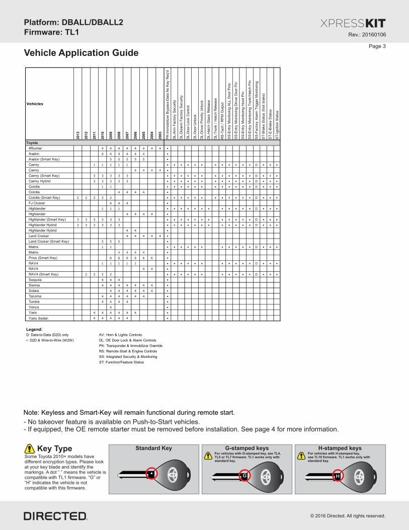
Installation Type 3a (without T-Harness)
[1] (AC) Tach Input
(-) Trunk Status Input
(-) Door Status Input
(-) E-Brake Status Input
Rem
ote
Sta
rter
(-) GWR (Status)
(-) Lock Output
(+) Ignition Input
(+) Starter Output
(-) Unlock Output
(-) Trunk Output [3]
(+) 12V
(-) Ground
(+) Brake Input
1: Green: (-) Lock Input
2: Blue: (-) Unlock Input
3: Red/White: (-) Trunk Input
9: Pink: (+) Ignition Input
8: Violet: (+) Starter Input
10: Blue/White: (-) GWR (Status) Input
HS CAN High: Tan/Black: 3
HS CAN Low: Tan: 4
(+) 12V Input: Brown: 7
[2] (+) STSW Output: Yellow: 8
(+) 12V: Red: 13
(-) Ground: Black: 14
[1] (AC) Tach Output: Violet/White: 5
(-) Push-to-Start Output: Green/Black: 2
(-) Door Status Output: Green/White: 3
(-) Trunk Status Output: Red/Black: 4
HS CAN High:pin 6
HS CAN Low:pin 14
(-) Parking Lights
[2] (+) STSW:pin 4 or 6
(-) Hood Status Input
(-) Hood Status Output: Blue/Red: 12
White Conn.(at Fuse Box)
(+)12V Black wirepin 1
1
White Conn.(at back of main body ECU)
(-) Ground
(+) 12V
(-) Ground
D o n o t c o n n e c t a n y o t h e r accessory, ignition or starter wires from the remote starter to the vehicle. The interface module is handling the required vehicle power and start sequence.
(+) Brake Output: Gray: 6
(+) Ignition Status Output: Gray/Black: 7
(-) Push-to-Start: pin 7
ENGINESTARTSTOP
BlackConnector
1 5 4 3 1
81112 10 914
6
13
27
See page 12 for help on locating key components in the vehicle and wiring reference chart.
DBALL/DBALL2
RF
Prog. Button
LED
4
TX
(-) Ground
RX(+)12V
14
12
2
10
P#: XKD2D65
[2] STSW: Starter Switch Wire. Refer to the wiring reference chart on page 12 for wire color and connections.
Not required in D2D mode.
[1] Tach wire is an optional connection required on some remote starters, which do not support a tach signal in D2D.
With the exception of the OBDII Diagnostic connector, all adapters are displayed from the wire side (unless specified otherwise).
Connection required only if Pit-Stop/ Idle mode is desired (see details on page 12).(Connector side view).
(-) Parking Lights: Black, pin 18
White Conn.(at headlight switch)
12345678910
1112131415161720 19 18
(-) E-Brake Status Output: Black/White: 1
12
356
78910
4
Rev.: 20160106
Platform: DBALL/DBALL2Firmware: TL1
© 2016 Directed. All rights reserved.
(-) Push-to-Start: pin 7
1 5 4 3 1
81112 10 914
6
13
2ENGINESTARTSTOP 7
BlackConnector
Connection required only if Pit-Stop/ Idle mode is desired. (see details on page 12).(Connector side view)
Page 11
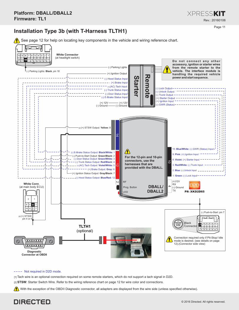
Installation Type 3b (with T-Harness TLTH1)
[2] STSW: Starter Switch Wire. Refer to the wiring reference chart on page 12 for wire color and connections.
DiagnosticConnector at OBDII
1 8
169
DBALL/DBALL2
RF
Prog. Button
LED
[2] (+) STSW Output: Yellow: 8
4
2
10
14
12
For the 12-pin and 10-pinconnectors, use the harnesses that are provided with the DBALL.
(-) Push-to-Start Output: Green/Black: 2
Rem
ote
Sta
rter
D o n o t c o n n e c t a n y o t h e r accessory, ignition or starter wires from the remote starter to the vehicle. The interface module is handling the required vehicle power and start sequence.
TX
(-) Ground
RX(+)12V
P#: XKD2D65
(-) Ground (-) Ground(+) 12V(+) 12V
(+) Ignition Output
(+) Ignition Status Output: Gray/Black: 7
(-) Parking Lights
With the exception of the OBDII Diagnostic connector, all adapters are displayed from the wire side (unless specified otherwise).
[1] Tach wire is an optional connection required on some remote starters, which do not support a tach signal in D2D.
[1] (AC) Tach Output: Violet/White: 5
[1] (AC) Tach Input
Not required in D2D mode.
See page 12 for help on locating key components in the vehicle and wiring reference chart.
TLTH1(optional)
1: Green: (-) Lock Input
2: Blue: (-) Unlock Input
3: Red/White: (-) Trunk Input
9: Pink: (+) Ignition Input
8: Violet: (+) Starter Input
10: Blue/White: (-) GWR (Status) Input
(-) GWR (Status)
(-) Lock Output
(+) Starter Output
(-) Unlock Output
(-) Trunk Output
(+) Ignition Input
(-) E-Brake Status Output: Black/White: 1
(-) Door Status Output: Green/White: 3
(-) Trunk Status Output: Red/Black: 4
(+) Brake Output: Gray: 6
(-) Hood Status Output: Blue/Red: 12
(-) Trunk Status Input
(-) Door Status Input
(-) E-Brake Status Input
(+) Brake Input
(-) Hood Status Input
(-) Parking Lights: Black, pin 18
White Connector(at headlight switch)
12345678910
1112131415161720 19 18
White Conn.(at main body ECU)
12
356
78910
4
[2] (+) STSW:pin 4 or 6

Rev.: 20160106
Platform: DBALL/DBALL2Firmware: TL1
© 2016 Directed. All rights reserved.
Wire function Connector Pin position Wire color
CAN High Diagnostic Connector 6 Light Green
CAN Low Diagnostic Connector 14 Pink
Autolight Main Body ECU (E61) 21 Yellow
Parking Lights Main Body ECU (E61) 23 Black
Push-to-Start PTS button 7 Blue
STSW* Main Body ECU (E58) 4 or 6 Red or Violet
12V Fuse Box (DA) 1 White
CAN High Diagnostic Connector 6 Black
CAN Low Diagnostic Connector 14 White
Autolight Main Body ECU (E7) 21 Green
Parking Lights Main Body ECU (E7) 23 Black
Push-to-Start PTS button 7 Blue
STSW* Main Body ECU (E9) 4 or 6 Gray or Violet
12V Fuse Box (1A) 1 Black
CAN High Diagnostic Connector 6 Black
CAN Low Diagnostic Connector 14 White
Autolight Main Body ECU (E7) 21 Green
Parking Lights Main Body ECU (E7) 23 Black
Push-to-Start PTS button 7 Blue
STSW* Main Body ECU (E9) 4 Gray
12V Fuse Box (1A) 1 Black
CAN High Diagnostic Connector 6 Black
CAN Low Diagnostic Connector 14 White
Autolight Main Body ECU (D8) 21 Green
Parking Lights Main Body ECU (D8) 23 Light Blue
Push-to-Start PTS button 7 Pink
STSW* Main Body ECU (D10) 4 Pink
12V Fuse Box (1A) 1 Black
CAN High Diagnostic Connector 6 Black
CAN Low Diagnostic Connector 14 White
Autolight Main Body ECU (D8) 21 Green
Parking Lights Main Body ECU (D8) 23 Light Blue
Push-to-Start PTS button 7 Pink
STSW* Main Body ECU (D10) 4 Yellow
12V Fuse Box (1A) 1 Black
*STSW: Starter Switch
Toyota Camry
Hybrid
(Smart Key)
2007-2011
Toyota Camry
(Smart Key)
2007-2011
Lexus ES 350
(Smart Key)
2007-2012
Toyota
Highlander
(Smart Key)
2008-2013
Toyota
Highlander
Hybrid
(Smart Key)
2008-2013
Page 12
Wiring Reference Chart - Type 3
Pit-Stop/Idle ModeThe Pit-Stop/Idle feature allows the vehicle to remain running after leaving the vehicle.Refer to the owner's guide of your remote starter for more details.
WARNING- No takeover feature is available onPush-to-Start vehicles. See QuickReference Guide (QRG) at the endof this guide.
- To remote start the engine, all doorsmust be closed, including rear hatch.
Push-To-StartButton
Headlightswitch

Rev.: 20160106
Platform: DBALL/DBALL2Firmware: TL1
© 2016 Directed. All rights reserved.
Installation Type 4
(+) 12V(+) 12V
Page 13
See pages 14-15 for help on locating key components in the vehicle and wiring reference chart.
Connect to vehicleVisit our website :
www.directechs.comfor more information.
Autolight
9: Pink: (+) Ignition Input
10: Blue/White: (-) GWR (Status) Input
(-) Keysense Output: Yellow: 8
(-) Ground: Brown: 7(-) Ground
TX: Yellow/Black: 10
RX: Orange/Black: 11TX: pin 5 RX: pin 4
12347 6 5
Black 7-pin Connector(at immobilizer)
(+) 12V: Red: 13(+) 12V
(-) Ground (-) Ground: Black: 14
Not required in D2D mode.
DBALL/DBALL2
RF
Prog. Button
LED
4
TX
(-) Ground
RX(+)12V
14
12
2
10
P#: XKD2D65
With the exception of the OBDII Diagnostic connector, all adapters are displayed from the wire side (unless specified otherwise).
Autolight: Orange/Red: 10
Autolight: Yellow/Red: 11
(+) Ignition (some vehicles require 2 ignitions)
(+) Starter 1 Output
Rem
ote
Sta
rter
(-) GWR (Status)
(-) Ground(-) Ground
nd(+) Start 2 (some vehicles require 2 start)
[1] (AC) Tach Input
(+) Brake Input
(-) Lock Output
(-) Unlock Output
(-) Trunk Output
Connect toIgnition ConnectorVisit our website :
www.directechs.comfor more information.
(-) Parking Lights Output(+) Accessory (some vehicles require 2 accessories)
Automatic Transmission:Connect to vehicle’s starter.
Manual Transmission:Connect to vehicle’s clutch.
OR
(+) Starter
For Manual Transmission vehicles ONLY.
Refer to www.directechs.com for clutch wire colors,
pin numbers andconnector details.
Rev.: 20160106
Platform: DBALL/DBALL2Firmware: TL1
© 2016 Directed. All rights reserved.
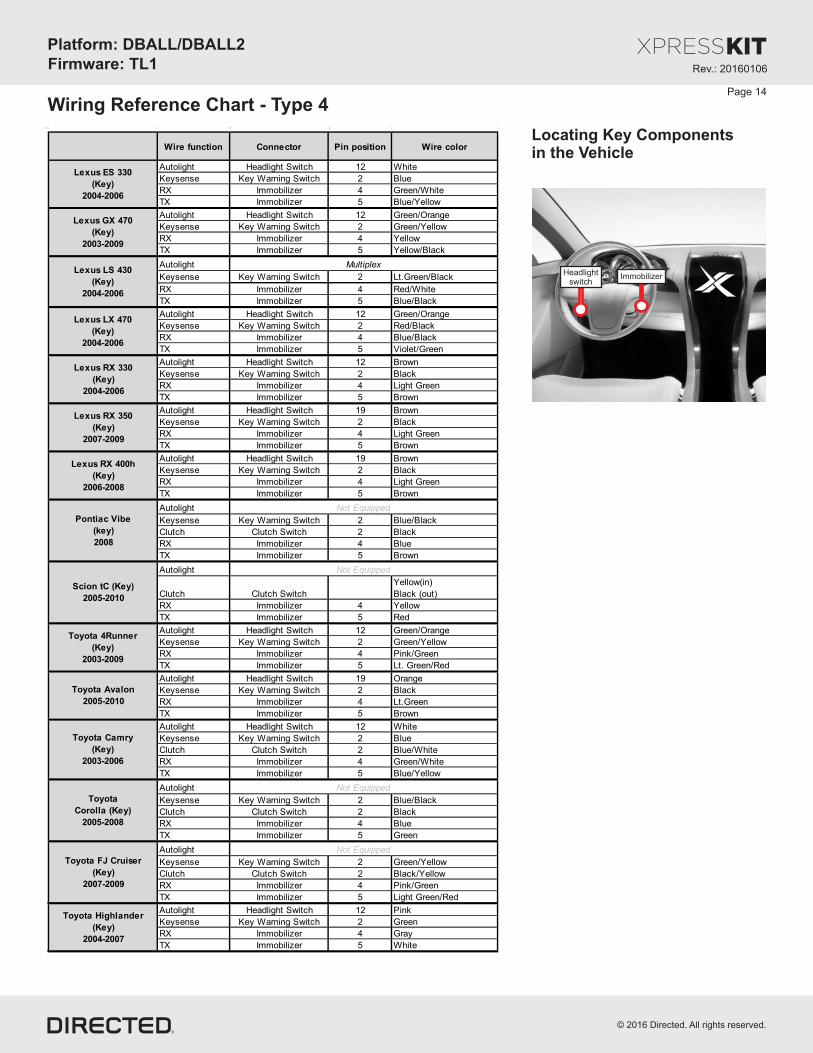
Wiring Reference Chart - Type 4
Locating Key Componentsin the Vehicle
Wire function Connector Pin position Wire color
Autolight Headlight Switch 12 White
Keysense Key Warning Switch 2 Blue
RX Immobilizer 4 Green/White
TX Immobilizer 5 Blue/Yellow
Autolight Headlight Switch 12 Green/Orange
Keysense Key Warning Switch 2 Green/Yellow
RX Immobilizer 4 Yellow
TX Immobilizer 5 Yellow/Black
Autolight
Keysense Key Warning Switch 2 Lt.Green/Black
RX Immobilizer 4 Red/White
TX Immobilizer 5 Blue/Black
Autolight Headlight Switch 12 Green/Orange
Keysense Key Warning Switch 2 Red/Black
RX Immobilizer 4 Blue/Black
TX Immobilizer 5 Violet/Green
Autolight Headlight Switch 12 Brown
Keysense Key Warning Switch 2 Black
RX Immobilizer 4 Light Green
TX Immobilizer 5 Brown
Autolight Headlight Switch 19 Brown
Keysense Key Warning Switch 2 Black
RX Immobilizer 4 Light Green
TX Immobilizer 5 Brown
Autolight Headlight Switch 19 Brown
Keysense Key Warning Switch 2 Black
RX Immobilizer 4 Light Green
TX Immobilizer 5 Brown
Autolight
Keysense Key Warning Switch 2 Blue/Black
Clutch Clutch Switch 2 Black
RX Immobilizer 4 Blue
TX Immobilizer 5 Brown
Autolight
Clutch Clutch Switch
Yellow(in)
Black (out)
RX Immobilizer 4 Yellow
TX Immobilizer 5 Red
Autolight Headlight Switch 12 Green/Orange
Keysense Key Warning Switch 2 Green/Yellow
RX Immobilizer 4 Pink/Green
TX Immobilizer 5 Lt. Green/Red
Autolight Headlight Switch 19 Orange
Keysense Key Warning Switch 2 Black
RX Immobilizer 4 Lt.Green
TX Immobilizer 5 Brown
Autolight Headlight Switch 12 White
Keysense Key Warning Switch 2 Blue
Clutch Clutch Switch 2 Blue/White
RX Immobilizer 4 Green/White
TX Immobilizer 5 Blue/Yellow
Autolight
Keysense Key Warning Switch 2 Blue/Black
Clutch Clutch Switch 2 Black
RX Immobilizer 4 Blue
TX Immobilizer 5 Green
Autolight
Keysense Key Warning Switch 2 Green/Yellow
Clutch Clutch Switch 2 Black/Yellow
RX Immobilizer 4 Pink/Green
TX Immobilizer 5 Light Green/Red
Autolight Headlight Switch 12 Pink
Keysense Key Warning Switch 2 Green
RX Immobilizer 4 Gray
TX Immobilizer 5 White
Toyota
Corolla (Key)
2005-2008
Toyota Highlander
(Key)
2004-2007
Toyota FJ Cruiser
(Key)
2007-2009
Not Equipped
Not Equipped
Lexus ES 330
(Key)
2004-2006
Lexus GX 470
(Key)
2003-2009
Lexus LS 430
(Key)
2004-2006
Toyota Camry
(Key)
2003-2006
Toyota 4Runner
(Key)
2003-2009
Lexus LX 470
(Key)
2004-2006
Lexus RX 330
(Key)
2004-2006
Lexus RX 350
(Key)
2007-2009
Lexus RX 400h
(Key)
2006-2008
Multiplex
Toyota Avalon
2005-2010
Scion tC (Key)
2005-2010
Not Equipped
Pontiac Vibe
(key)
2008
Not Equipped
ImmobilizerHeadlightswitch
Page 14

Rev.: 20160106
Platform: DBALL/DBALL2Firmware: TL1
© 2016 Directed. All rights reserved.
Wiring Reference Chart - Type 4 (cont’d)
Locating Key Componentsin the Vehicle
ImmobilizerHeadlightswitch
Page 15
Wire function ConnectorPin
positionWire color
Autolight Headlight Switch 12 Pink
Keysense Key Warning Switch 2 Green
RX Immobilizer 4 Gray
TX Immobilizer 5 Lt.Blue
Autolight Headlight Switch 12 Green/Orange
Keysense Key Warning Switch 2 Red/Black
RX Immobilizer 4 Blue/Black
TX Immobilizer 5 Violet/Green
Autolight
Keysense Key Warning Switch 2 Blue/Black
Clutch Clutch Switch 2 Black
RX Immobilizer 4 Blue
TX Immobilizer 5 Green
Autolight
Keysense Key Warning Switch 2 Blue/Red or White
Clutch Clutch Switch 1 Black/Yellow
RX Immobilizer 4 Blue/Red
TX Immobilizer 5 Pink
Autolight Headlight Switch 19 Green
Parking Lights Headlight Switch 18 Orange or Beige
RX Immobilizer 4 Lt.Green
TX Immobilizer 5 Blue
Autolight Headlight Switch 12 Violet
Keysense Key Warning Switch 2 Blue/Black
RX Immobilizer 4 YellowTX Immobilizer 5 Yellow/Red
Autolight Headlight Switch 12 or 19 White
Keysense Key Warning Switch 2 Blue
Clutch Clutch Switch 2 Black/White
RX Immobilizer 4 Yellow or Green/White
TX Immobilizer 5Yellow/Red or
Blue/Yellow
Autolight
Parking Lights Headlight Switch 18 Green
Clutch Clutch Switch 2 Black/Yellow
RX Immobilizer 4 Pink/Green
TX Immobilizer 5 Lt. Green/Red
Autolight Headlight Switch 19 Green
Parking Lights Headlight Switch 18 Orange or Beige
RX Immobilizer 4 Lt.Green
TX Immobilizer 5 Blue
Autolight Headlight Switch 19 Brown
Keysense Key Warning Switch 1 Brown
RX Immobilizer 4 Lt. Green
TX Immobilizer 5 Brown
Autolight
Keysense Key Warning Switch 1 Yellow
Clutch Clutch Switch 1 Black
RX Immobilizer 4 Green
TX Immobilizer 5 Violet
Toyota Highlander
Hybrid
2006-2007
Toyota Sequoia
(Key)
2008-2010
Toyota Land
Cruiser
(Key)
2003-2007
Not EquippedToyota Yaris
(Key)
2006-2011
Toyota Matrix
(Key)
2005-2008
Not Equipped
Not Equipped
Toyota Solara
(Key)
2004-2009
Toyota RAV4
(Key)
2004-2005
Not Equipped
Toyota Sienna
(Key)
2004-2010
Toyota Venza
(Key)
2009
Toyota Tundra
(Key)
2007-2010
Toyota Tacoma
(Key)
2005-2010

Rev.: 20160106
Platform: DBALL/DBALL2Firmware: TL1
© 2016 Directed. All rights reserved.
Do not connect any other accessory, ignition or starter wires from the remote starter to the vehicle. The interface module is handling the required vehicle power and start sequence.
Page 16
Installation Type 5
Rem
ote
Sta
rter
(-) GWR (Status)
(+) Ignition Output/Input
(+) Starter Output
9: Pink: (+) Ignition Input
8: Violet: (+) Starter Input
10: Blue/White: (-) GWR (Status) Input
(+) Brake Activation Output: Yellow: 8
Data TX: Yellow/Black: 10
(-) Push-To-Start Output: Green/Black: 2
Data RX: Orange/Black: 11
(-) Ground: Black: 14
(-) Push-to-Start: pin 7
ENGINESTARTSTOP
BlackConnector
(+) 12V
(-) Ground(-) Ground
(+) Brake Input
Brake Switch(at brake switch)
(-) Ground
(+) 12V: Brown: 7
(+) 12V: Red: 13(+) 12V
1 5 4 3 1
81112 10 914
6
13
27
See page 17 for help on locating key components in the vehicle and wiring reference chart.
DBALL/DBALL2
RF
Prog. Button
LED
4
TX
(-) Ground
RX(+)12V
14
12
2
10
P#: XKD2D65
142
3
Connect to vehicleVisit our website :
www.directechs.comfor more information.
TX: pin 9
RX: pin 10
Note: the OEM alarm arm/disarmwires will also control the door locks.You need to configure the remote starterto unlock the doors before start,and relock after start or turn ON feature called Safelock which is found in many Directed Premium Remote Start Systems.
Parking Lights
AC Tach Input
(-) Trunk Output
With the exception of the OBDII Diagnostic connector, all adapters are displayed from the wire side (unless specified otherwise).
(+) Brake: pin 1
(+) Brake Output: Orange/Yellow: 9
Not required in D2D mode.
(+) Ignition: pin 3
(-) Hood Input
(-) Driver’s Door Trigger
Hood Pin
This connection is required to shut the Remote Start down when the Driver’s Door is open.

Rev.: 20160106
Platform: DBALL/DBALL2Firmware: TL1
© 2016 Directed. All rights reserved.
Locating Key Componentsin the VehicleWire function Connector Pin position Wire color
Push-To-Start PTS Button 7 Pink
RX PTS Button 10 Yellow
TX PTS Button 9 Blue
Brake Brake Switch 1 Red/Black
Push-To-Start PTS Button 7 Pink
RX PTS Button 10 Yellow
TX PTS Button 9 Blue
Brake Brake Switch 1 Red/Black
Push-To-Start PTS Button 7 Pink
RX PTS Button 10 Yellow
TX PTS Button 9 Blue
Brake Brake Switch 1 Red/Black
Push-To-Start PTS Button 7 Pink
RX PTS Button 10 Yellow
TX PTS Button 9 Blue
Brake Brake Switch 1 Red/Black
Push-To-Start PTS Button 7 Pink
RX PTS Button 10 Yellow
TX PTS Button 9 Blue
Brake Brake Switch 1 Red/Black
Push-To-Start PTS Button 7 Black
RX PTS Button 10 Light Blue
TX PTS Button 9 Blue
Clutch Clutch Switch 2 Red
Brake Brake Switch 1 Red/Black
Push-To-Start PTS Button 7 Black
RX PTS Button 10 Light Blue
TX PTS Button 9 Blue
Brake Brake Switch 1 Red/Black
Push-To-Start PTS Button 7 Black
RX PTS Button 10 Light Blue
TX PTS Button 9 Blue
Brake Brake Switch 1 Red/Black
Push-To-Start PTS Button 7 White
RX PTS Button 10 White
TX PTS Button 9 Orange
Brake Brake Switch 1 Blue
Push-To-Start PTS Button 7 White
RX PTS Button 10 White
TX PTS Button 9 Orange
Brake Brake Switch 1 Blue
Push-To-Start PTS Button 7 Blue
RX PTS Button 10 White
TX PTS Button 9 Gray
Brake Brake Switch 1 White
Push-To-Start PTS Button 7 Black
RX PTS Button 10 Green
TX PTS Button 9 Lt.Green
Brake Brake Switch 1 Red
Toyota Land
Cruiser
(Smart Key)
2008-2010
Lexus GS 300
(Smart Key)
2006
Lexus GS 350
(Smart Key)
2007-2008
Lexus GS 430
(Smart Key)
2006-2007
Lexus GS 450h
(Smart Key)
2007-2008
Lexus LS 600h
(Smart Key)
2008
Lexus GS 460
(Smart Key)
2008
Lexus IS 350
(Smart Key)
2006-2008
Lexus IS 250
(Smart Key)
2006-2008
Lexus IS F
(Smart Key)
2008
Lexus LS 460
(Smart Key)
2007-2008
Toyota Avalon
(Smart Key)
2008-2009
Page 17
Wiring Reference Chart - Type 5
BrakeSwitch
Push-To-StartButton
WARNING
- No takeover feature is available on Push-to-Start vehicles. See Quick Reference Guide (QRG) at the end of this guide.- To remote start the engine, all doors must be closed, including rear hatch.

Rev.: 20160106
Platform: DBALL/DBALL2Firmware: TL1
© 2016 Directed. All rights reserved.
(+) 12V
(-) Ground(-) Ground
(+) Brake Input
142
3
Parking Lights
AC Tach Input
(-) Trunk Output
Page 18
Installation Type 6
Not required in D2D mode.
Rem
ote
Sta
rter
(+) Brake Activation Output: Yellow: 8
(-) Push-To-Start Output: Green/Black: 2
(+) 12V: Red: 13
(-) Ground: Black: 14
(-) Push-to-Start: Yellow, pin 7
Key Release:Pink, pin 5
(-) Key Sense:Blue, pin 3
ENGINESTARTSTOP
BlackConnector
(+) 12V
(-) Ground
DBALL/DBALL2
RF
Prog. Button
LED
4
TX
(-) Ground
RX(+)12V
14
12
2
10
P#: XKD2D65
TX: Yellow/Black: 10
RX: Orange/Black: 11
TX: Lt. Green, pin 5
RX: Blue, pin 4
12347 6 5
Black 7-pin Connector(at key port)
Black 5-pin Connector(at key port)
(+) 12V
30
86 8587
87a
(+) 12V: Brown: 7
9: Pink: (+) Ignition Input
8: Violet: (+) Starter Input
10: Blue/White: (-) GWR (Status) Input
(-) GWR (Status)
(+) Ignition Output/Input
(+) Starter Output
1 2 3 4 5 6 7 8
1 2 3 4 5
Connect to vehicleVisit our website :
www.directechs.comfor more information.
Note: the OEM alarm (if equipped)will arm/disarm with the lock/unlockwires. You need to configure the remote starter to unlock the doors before start, and relock after start.
With the exception of the OBDII Diagnostic connector, all adapters are displayed from the wire side (unless specified otherwise).
(+) Brake: pin 1
(+) Brake Output: Orange/Yellow: 9
(+) Ignition: pin 3
(-) Hood Input
(-) Driver’s Door Trigger
This connection is required to shut the Remote Start down when the Driver’s Door is open.
Hood Pin
Brake Switch(at brake switch)

Rev.: 20160106
Platform: DBALL/DBALL2Firmware: TL1
© 2016 Directed. All rights reserved.
Locating Key Components in the Vehicle
Wire function Connector Pin position Wire color
Push-To-Start PTS Button 7 Yellow
Keysense Key Port 3 Blue
Key Release Key Port 5 Pink
RX Keyport 4 Blue
TX Keyport 5 Light Green
Brake Brake Switch 1 Blue
Prius
2004-2009
Page 19
Wiring Reference Chart - Type 6
BrakeSwitch
Push-To-StartButton
WARNING- No takeover feature is available on Push-to-Start vehicles. See Quick Reference Guide (QRG) at the end of this guide.- To remote start the engine, all doors must be closed, including rear hatch.

Page 20
Module Programming
Refer to the LED Diagnostics section on page 25 for more information and for troubleshooting purposes.
1Solid
Wait until the LED turns ON solid red.
Method for Installation Type 1 vehicles: Key-type vehicles with CAN
2
3 Turn ignition to ON position. The LED turns ON solidgreen for 3 seconds then turns OFF.
IGN
ON
OF
F
KEY
Flashes Redslowly
Go to the next page to see the Types 2, 3 & 4 module programming.
Insert the key in the ignition switch. The LED flashes red slowly for a few seconds to indicate the key is in learning mode. The LED turns ON solid green.*
* If the LED starts to flash orange, it indicates the vehicle is equipped with a factory remote starter. Refer to LED Diagnostics & Troubleshooting section for more information.
&Solid Green
Solid Green3 secs.
Off
&&
&
OR
If required for your installation, connect the 10-pin, 12-pin and 14-pin harnesses to the module, then connect the 4-pin D2D harness.
D2D Installation
W2W Installation
If required for your installation, connect the 10-pin and 12-pin harnesses to the module, then connect the 14-pin harness to the module.
10-pinD2D
st1
12-pin14-pin
nd2
rd3
10-pinD2D
st1
th4
12-pin14-pin
nd2
rd3
KEY ACC
ON
OF
F
4 The module is now programmed. Remove the key from the ignition. ACC
ON
OF
F
KEY
ImportantMake all the required connections to the vehicle, as described in the wiring diagram(s) found in this guide, and double check to ensure everything is correct prior to moving onto the next step.
Warning! To take advantage of advanced features, you must use XpressVIP 4.5 (and higher) or the Directechs Mobile app.
When the flashing operation is successful, you can proceed with the programming instructions below.
Flashing a module using your computer:
1. Connect the interface module to your computer using the XKLoader2.
2. Go to www.directechs.com using Internet Explorer, and select the Flash Module button.
3. Follow the instructions to select your vehicle, installation type, and configure your options.
4. Once you have configured the firmware options, click on the FLASH button.
Flashing a module using your smartphone or tablet
1. Connect the interface module to your XKLoader3.
2. Launch the Directechs Mobile app on your smartphone or tablet.
3. Select FLASH YOUR MODULE and follow the on screen instructions.
Rev.: 20160106
Platform: DBALL/DBALL2Firmware: TL1
© 2016 Directed. All rights reserved.

Module Programming
Method for Installation Types 2 & 3 vehicles: Push-To-Start (PTS) vehicles with CAN
Solid Greenx3 secs.
Flashes Redslowly2
Press the PTS button twice to turn the ignition ON. The LED flashes red slowly for few seconds to indicate the key is in learning mode. The LED turns ON solid green for 3 seconds, and then shuts OFF*.
* If the LED starts to flash orange, it indicates the vehicle is equipped with a factory remote starter. Refer to LED Diagnostics & Troubleshooting section for more information.
3 The module is now programmed, press the PTS button once more to turn the ignition OFF.
ENGINESTARTSTOP
PUSH 1X
ENGINESTARTSTOP
PUSH 2X
Off
& &
&
Method for Installation Type 4 vehicles: Key-type vehicles without CAN
2 IGN
ON
OF
F
KEY
Flashes Redslowly
Insert the key in the ignition switch. The LED flashes red slowly for few seconds to indicate the key is in learning mode then the LED turns ON solid green.
&Solid Green
&
You have successfully completed the module programming sequence.
Go to the next page to see the Type 5 module programming.
4 The module is now programmed. Remove the key from the ignition.ACC
ON
OF
F
KEY
You have successfully completed the module programming sequence.
Page 21
Press the IPB 5 times to skip the CAN programming. The LED will turn OFF quickly then the green LED will turn ON for 3 seconds.
Solid Greenx3 secs.
Solid Greenx3 secs.
Off
& &&Press 5x
3
Rev.: 20160106
Platform: DBALL/DBALL2Firmware: TL1
© 2016 Directed. All rights reserved.

Page 22
Module Programming
Method for Installation Types 5 & 6 vehicles: Push-To-Start (PTS) vehicles without CAN
Open the OEM key fob and remove the battery, then place the OEM key fob in front of the PTS button.
2
Flashes Redslowly
Solid Green
3Press the PTS button twice to turn the ignition ON. The LED flashes red slowly for few seconds to indicate the key is in learning mode, then the LED turns ON solid green.
5 The module is now programmed, press the PTS button once more to turn the ignition OFF.
ENGINESTARTSTOP
PUSH 1X
ENGINESTARTSTOP
PUSH 2X & &
You have successfully completed the module programming sequence.
RemoveBattery
HOLD
Solid Greenx3 secs.
Solid Greenx3 secs.
Off
& &&Press 5x
4Press the IPB 5 times to skip the CAN programming. The LED will turn OFF quickly then the green LED will turn ON for 3 seconds.
For Prius (Smart Key) 2004-2009 Insert key fob into keyport.
Rev.: 20160106
Platform: DBALL/DBALL2Firmware: TL1
© 2016 Directed. All rights reserved.

2
Solid
&
Solid Flashes
&
Release
3
Wait 3 seconds until the LED turns ON solid orange, and wait 10 more seconds until the LED starts to flash orange and red.
Release the programming button. The LED turns ON solid red.
Warning Against Executing a Hard Reset! A hard reset will revert the flashed firmware back to its default settings. Depending on the installation, some settings (such as RFTD and D2D options) may have to be reconfigured. See the Feature & Option List section of this guide.
1 OR
If required for your installation, connect the 10-pin, 12-pin & 14-pin harnesses to the module. Press and hold the programming button, then connect the 4-pin D2D harness.
D2D Installation
If required for your installation, connect the 10-pin & 12-pin harnesses to the module. Press and hold the programming button, then connect the 14-pin harness to the module.
W2W Installation
10-pinD2D
st1
12-pin14-pin
nd2
th4
rd3
10-pinD2D
st1
th5
12-pin14-pin
nd2
rd3
th4
Module Reset
Hard Reset
2 & &Solid SolidRelease
Wait 3 seconds until the LED turns ON solid orange then release the programming button. The LED then turns ON solid red.
A module reset will only erase programming performed in the previous steps. All settings (firmware) and settings flashed to the module using the web config tool will not be affected.
1 OR
If required for your installation, connect the 10-pin, 12-pin & 14-pin harnesses to the module. Press and hold the programming button, then connect the 4-pin D2D harness.
D2D Installation
If required for your installation, connect the 10-pin & 12-pin harnesses to the module. Press and hold the programming button, then connect the 14-pin harness to the module.
W2W Installation
10-pinD2D
st1
12-pin14-pin
nd2
th4
rd3
10-pinD2D
st1
th5
12-pin14-pin
nd2
rd3
th4
Page 23
Rev.: 20160106
Platform: DBALL/DBALL2Firmware: TL1
© 2016 Directed. All rights reserved.

Page 24
Feature & Option List
* Default option
Feature Operation Flashes / Option Description
1. Disabled* Module is connected to a remote starter using a standard installation.
2. RFTD OutputModule is connected to an XL202 using an RSR or RXT installation (when
available).
3. SmartStartModule is connected to SmartStart using an RSR or RXT installation (when
available).
1. Driver Priority*Unlocks only the driver door on first press and unlocks all doors on a second
press within 5 seconds.
2. All Unlocks all doors on first press.
1. Disabled
2. Trunk*
3.Tail Glass Opening
1. Disabled
2. Trunk
3. Tail Glass Opening*
1. Disabled
The OEM alarm will not be controlled by DBALL upon remote start. No disarm
or arm command will be executed at the beginning or end of the sequence; it
must be controlled by the Remote Starter.
2. Normal
Smart OEM Alarm Control will behave like a standard Safelock feature on a
remote starter. It will unlock at the beginning of the sequence, and relock after
start and shutdown.
3. Smart OEM Alarm Control*
Smart OEM Alarm Control will synchronize with the OEM alarm so that it will
disarm and rearm the vehicle in the remote start sequence, only when
required. The reason for this is, factory alarm control must often be done by
lock or unlock operation. This could create unnecessary actions on door lock
modules, such as the horn to honk. When possible, Smart OEM Alarm
Control will monitor the alarm and door lock status to detect if the disarm or
rearm is required. If the vehicle is unlocked or is not equipped with factory
alarm, the disarm/rearm will not be executed. Smart OEM Alarm Control will
also monitor the remote starter actions so that the factory alarm control is not
done twice. A remote starter, for which the Safelock feature is active, will work
perfectly with this option and will make it invisible to the user.
5 Smart OEM Alarm Control
Unlock Driver Priority2
1 RF Output Type
Trunk
Aux1
3
4
1. Disabled: doesn't operate any function in the vehicle.
3.Tail Glass Opening: When available, will operate the tail glass.
2. Trunk: Will pop the trunk if available.
It is recommended to configure all the features and options listed below using the configuration tool found on the module flashing page on www.directechs.com. The web offers more options; however, manual configuration of the features is possible using the information on this page.
To enter feature programming routine- For vehicles that are not Push-to-Start (PTS), use the key to turn the ignition ON, then OFF. For PTS vehicles, press the button twice to turn the
ignition ON, then press it once more to turn it OFF. - Within 5 sec, press and HOLD the programming button. The orange LED turns ON after 3 seconds. Release the button.- The green LED starts flashing slowly one time to indicate the feature number is 1. After a short delay, the red LED flashes rapidly to indicate the
current option of feature 1. It repeats until next action happens.
Changing feature options- Press the lock/arm or unlock/disarm button on aftermarket transmitter to change the option of the selected feature. - The red LED flashes rapidly the number of times equal to the current option number. After a short delay, the green LED flashes slowly the number of
times to indicate the current feature. It repeats until next action happens.
Accessing another feature- Press and release the programming button a number of times to advance from the current feature to the next desired feature. - The green LED flashes slowly the number of times equal to the feature number. After a short delay, the red LED flashes rapidly to indicate the
current option of the current feature. It repeats until next action happens.
When the maximum number of feature or option is reached, the LED will starts flashing again from the first feature or option.
Once a feature is programmed- Another feature(s) can be programmed.- The feature programming can be exited.
Exiting feature programming- No activity for 30 seconds; after 30 seconds, the orange LED will turn ON for 2 seconds to confirm exiting.
OR- Press and HOLD the for 3 seconds. After 3 seconds, the orange LED will turn ON for 2 seconds to confirm exiting.programming button
Feature ProgrammingProgramming
Button
Rev.: 20160106
Platform: DBALL/DBALL2Firmware: TL1
© 2016 Directed. All rights reserved.

Rev.: 20160106
Platform: DBALL/DBALL2Firmware: TL1
© 2016 Directed. All rights reserved.
LED Status Description TroubleshootingProgramming the Module
Off Module has no power.
Make sure the D2D harness is connected or that the 12 Volt is
present between the red and black wires. If the 12 Volt is present,
the module may be defective.
Solid RedWaiting to begin the
programming sequence.
Refer to the wiring diagram to make sure that all the connections
are correct.
Solid GreenCan not connect. Wating for 5x
IPB
Refer to the wiring diagram to make sure that CAN connections
are correct.
Flashes Red
slowlyLearning Mode Normal operation.
Flashes Orange OEM remote starter detected.
If the user wants to use the module as a convenience only, he
should skip bypass by pressing the programming button 5 times.
However, if the user wants to use the module as a remote starter,
he should disconnect the OEM remote starter and repeat the
programming sequence.
Solid Green x3
seconds
Module has been successfully
programmed.Normal operation.
Solid Orange x3
seconds
Module was successfully
programmed without bypass
(convenience only).
Normal operation. An OEM remote starter was detected
(convenience mode only). If the user wants to use the module as
a remote starter, he should disconnect the OEM remote starter
and repeat the programming sequence, by doing a short reset.
Active Ground While Running
Flashes GreenGROUND OUT ON (GWR)
command received.
Otherwise, the Ground While Running (status) signal was lost or
was never received by the module. Commands can come from
RF, D2D or W2W.
Flashes Red &
Orange
IGNITION ON command
received.
Otherwise, the ignition signal was not received by the module. In
a W2W install, it will show only if the ignition input wire is used.
Flashes Green
QuicklySTART ON command received.
Otherwise, the start signal was not received by the module.
Refer to the wiring diagram to make the right connections.
D2D & W2W Commands
Flashes Orange
x1LOCK command received.
Flashes Orange
x2UNLOCK command received.
Flashes Orange
x3TRUNK command received.
Flashes Orange
x4AUX1 command received.
Flashes Orange
x5AUX2 command received.
If the bypass module fails to flash, it means the module did not
receive the signal. Commands can come from RF, D2D or W2W.
LED Diagnostics & TroubleshootingPage 25
Solid red
Solid green
Flashes orange
Flashes redslowly
Solid orange x3 secs
Solid green x3 secs
Off
Flashesgreen
Flashesred &orange
Flashesgreen quickly
Flashesorange x1
Flashesorange x2
Flashesorange x3
Flashesorange x4
Flashesorange x5

For a period of ONE YEAR from the date of purchase of a Directed Electronics remote start or security product, Directed Electronics. (“DIRECTED”) promises to the original purchaser, to repair or replace with a comparable reconditioned piece, the security or remote start accessory piece (hereinafter the “Part”), which proves to be defective in workmanship or material under normal use, provided the following conditions are met: the Part was purchased from an authorized DIRECTED dealer; and the Part is returned to DIRECTED, postage prepaid, along with a clear, legible copy of the receipt or bill of sale bearing the following information: consumer’s name, address, telephone number, the authorized licensed dealer’s name and complete product and Part description.
This warranty is nontransferable and is automatically void if the Part has been modified or used in a manner contrary to its intended purpose or the Part has been damaged by accident, unreasonable use, neglect, improper service, installation or other causes not arising out of defect in materials or construction.
TO THE MAXIMUM EXTENT ALLOWED BY LAW, EXCEPT AS STATED ABOVE, ALL WARRANTIES, INCLUDING BUT NOT LIMITED TO EXPRESS WARRANTY, IMPLIED WARRANTY, WARRANTY OF MERCHANTABILITY, FITNESS FOR PARTICULAR PURPOSE AND WARRANTY OF NONINFRINGEMENT OF INTELLECTUAL PROPERTY, ARE EXPRESSLY EXCLUDED; AND DIRECTED NEITHER ASSUMES NOR AUTHORIZES ANY PERSON OR ENTITY TO ASSUME FOR IT ANY DUTY, OBLIGATION OR LIABILITY IN CONNECTION WITH ITS PRODUCTS. DIRECTED HEREBY DISCLAIMS AND HAS ABSOLUTELY NO LIABILITY FOR ANY AND ALL ACTS OF THIRD PARTIES INCLUDING DEALERS OR INSTALLERS. DIRECTED IS NOT OFFERING A GUARANTEE OR INSURANCE AGAINST VANDALISM, DAMAGE, OR THEFT OF THE AUTOMOBILE, ITS PARTS OR CONTENTS, AND DIRECTED HEREBY DISCLAIMS ANY LIABILITY WHATSOEVER, INCLUDING WITHOUT LIMITATION, LIABILITY FOR THEFT, DAMAGE, OR VANDALISM. IN THE EVENT OF A CLAIM OR A DISPUTE INVOLVING DIRECTED OR ITS SUBSIDIARY, THE PROPER VENUE SHALL BE SAN DIEGO COUNTY IN THE STATE OF CALIFORNIA. CALIFORNIA STATE LAWS AND APPLICABLE FEDERAL LAWS SHALL APPLY AND GOVERN THE DISPUTE. THE MAXIMUM RECOVERY UNDER ANY CLAIM AGAINST DIRECTED SHALL BE STRICTLY LIMITED TO THE AUTHORIZED DIRECTED DEALER’S PURCHASE PRICE OF THE PART. DIRECTED SHALL NOT BE RESPONSIBLE FOR ANY DAMAGES WHATSOEVER, INCLUDING BUT NOT LIMITED TO, ANY CONSEQUENTIAL DAMAGES, INCIDENTAL DAMAGES, DAMAGES FOR THE LOSS OF TIME, LOSS OF EARNINGS, COMMERCIAL LOSS, LOSS OF ECONOMIC OPPORTUNITY AND THE LIKE. NOTWITHSTANDING THE ABOVE, THE MANUFACTURER DOES OFFER A LIMITED WARRANTY TO REPLACE OR REPAIR AT DIRECTED’S OPTION THE PART AS DESCRIBED ABOVE.
This warranty only covers Parts sold within the United States of America and Canada. Parts sold outside of the United States of America or Canada are sold “AS-IS” and shall have NO WARRANTY, express or implied. Some states do not allow limitations on how long an implied warranty will last or the exclusion or limitation of incidental or consequential damages. This warranty gives you specific legal rights and you may also have other rights that vary from State to State. DIRECTED does not and has not authorized any person or entity to create for it any other obligation, promise, duty or obligation in connection with this Part.For further details relating to warranty information of Directed products, please visit the support section of DIRECTED’s website at: www.directed.com
920-10012-01 2013-07
This Interface kit / Data Bus Interface part has been tested on the listed vehicles. Other vehicles will be added to the select vehicle list upon completion of compatibility testing. Visit website for latest vehicle application guide. DISCLAIMER: Under no circumstances shall the manufacturer or the distributors of the bypass kit / data bus interface part(s) be held liable for any consequential damages sustained in connection with the part(s) installation. The manufacturer and it’s distributors will not, nor will they authorize any representative or any other individual to assume obligation or liability in relation to the interface kit / data bus interface part(s) other than its replacement. N.B.: Under no circumstances shall the manufacturer and distributors of this product be liable for consequential damages sustained in connection with this product and neither assumes nor authorizes any representative or other person to assume for it any obligation or liability other than the replacement of this product only.
Protected by U.S. Patents: 5,719,551; 6,011,460 B1 *; 6,243,004 B1; 6,249,216 B1; 6,275,147 B1; 6,297,731 B1; 6,346,876 B1; 6,392,534 B1; 6,529,124 B2; 6,696,927 B2; 6,756,885 B1; 6,756,886 B2; 6,771,167 B1; 6,812,829 B1; 6,924,750 B1; 7,010,402 B1; 7,015,830 B1; 7,031,826 B1; 7,046,126 B1; 7,061,137 B1; 7,068,153 B1; 7,205,679 B1; Cdn. Patent: 2,320,248; 2,414,991; 2,415,011; 2,415,023; 2,415,027; 2,415,038; 2,415,041; 2,420,947; 2,426,670; 2,454,089; European Patent: 1,053,128; Pat. Pending: 2,291,306. Made in Canada.
Limited One Year Consumer WarrantyPage 26
Rev.: 20160106
Platform: DBALL/DBALL2Firmware: TL1
© 2016 Directed. All rights reserved.

Vehicle Takeover for Push-To-Start vehicles
Quick Reference GuideDBALL/DBALL2-TL1
© 2016 Directed. All rights reserved.
Note: Takeover feature is not available on Push-to-start vehicles. The engine will stop when a door is opened.
Button(s) Actions
Press & hold for 1 second to lock.
Press & hold for 1 second to unlock.
Press & hold for 1 second to remote
start.
Press & hold for 5 seconds to activate
the trunk release (optional).
Press once, then to activate the
rear hatch/tail glass release (optional).*
Press 3 times, then to activate
the panic mode.
Press once, then to reset the
remote starter runtime.
List of Available Commands
x1 +
x3 +
x1 +
* This output is configurable. see your authorized installation center for more information.
Notes

![STANDOX TOYOTA 2010 [Kompatibilitätsmodus]info.pages.color.tc/Yellowpages/SX/TOYOTA/TOYOTA Colour Info.pdf · TOYOTA MODELS / MODELLE VIN / TYPENSCHILD 01 Corolla Corolla Fielder](https://img.pdfslide.us/doc/110x75/5b5543817f8b9a575f8de257/standox-toyota-2010-kompatibilitaetsmodusinfopagescolortcyellowpagessxtoyotatoyota.jpg)