Embed Size (px)
Citation preview

Rev.: 20 701 831
Platform: DBALL2
Firmware HKHT1:
© 201 Directed.7 All rights reserved.
Vehicle Application Guide.............. ..............................................................................................................................
Installation s s(Wiring Diagram & Vehicle Wiring Reference Chart )Type 1........................................................................... ..............................................................................................Type 2........................................................................... ..............................................................................................Type 3........................................................................... ..............................................................................................
ProgrammingType 1: Module Programming .....................................................................................................................................Type 2 & 3: Module Programming.................. ..........................................................................................................s .Module Reset.. ............................................................................................................................................................Hard ...Reset.. .............................................................................................................................................................Feature & Option List .... ............................................................................................................................................. .Feature Programming .... ............................................................................................................................................ .
LED Diagnostics & Troubleshooting........ ....................................................................................................................
Limited One-Year Consumer Warranty........................................................................................................................
Quick Reference Guide...............................................................................................................................................
02
030711
141516161717
18
20
21
® their respective companiesHyundai & Kia are registered trademarks and property of .
Index
Installation Guide
Update Alert: Firmware updates are posted the web on a regular basis. We recommendon
that you check for firmware and/or install guide updates prior to installing this product.
The firmware for 2 is an all-in-one door lock and override module compatible withHKHT1 DBALLspecific and vehicles.Hyundai Kia
This module can only be flashed and configured using Xpress at www.directechs.com orVIPusing the Directechs Mobile application for smartphones. Refer to the Module Programmingsection non page for more information.

Rev.: 20 701 831
Platform: DBALL2
Firmware HKHT1:
© 201 Directed.7 All rights reserved.
Vehicle Application GuidePage 2
The following table lists the vehicles and features which are compatible with this product. The number assigned to eachyear allows you to determine which installation type should be used for your vehicle.
Vehicles
2017
2016
2015
2014
2013
2012
2011
2010
2009
2008
PK
-Im
mobilizer
Bypass-D
ata
No
Key
Req'd
DL-A
rmF
acto
ryS
ecurity
DL-D
isarm
Facto
ryS
ecurity
DL-D
oor
Lock
Contr
ol
DL-D
oor
Unlo
ck
DL-
Driver
Priority
Unlo
ck
DL-T
runk
/H
atc
hR
ele
ase
FO
B-C
ontr
ol o
fafterm
ark
etala
rmw
ithO
EM
rem
ote
RS
-RA
PS
hutD
ow
n(R
eta
ined
AC
CP
ow
er)
RS
-Tach
/R
PM
Outp
ut
SS
-Entr
yM
onito
ring
ALL
Door
Pin
s
SS
-Entr
yM
onito
ring
Hood
Pin
SS
-Entr
yM
onito
ring
Tru
nk/H
atc
hP
in
ST
-Bra
ke
Sta
tus
(footbra
ke)
ST
-E-B
rake
Sta
tus
Hyundai
Accent 3 3 3 3 3 3 • • •
Accent 2 2 2 2 • •
Elantra 1 1 1 1 1 1 • • • • • • • D • • • • • • •
Elantra 2 2 2 • •
Elantra Coupe 1 1 • • • • • • • D • • • • •
Elantra Touring 3 3 3 3 • •
Genesis Coupe 2 2 2 • •
Santa Fe 3 3 3 3 3 • • •
Sonata 1 1 1 1 • • • • • • • D • • • • • • •
Sonata 2 2 2 • •
Tucson 1 1 1 1 1 1 • • • • • • • D • • • • • • •
Kia
Forte 3 3 3 3 • • •
Forte5 3 3 3 • • •
Magentis 2 2 • •
Optima 1 1 1 1 1 • • • • • • • D • • • • • • •
Optima 2 2 2 • •
Rio 2 2 2 2 • •
Rondo 3 3 3 3 3 • • •
Sorento 1 1 1 1 1 • •
Soul 3 3 3 3 • • •
Sportage 1 1 1 1 1 1 • • • • • • • D • • • • • • •
Sportage (4-cylinder) 2 2 2 • •
Sportage (V6) 2 2 2 • •
Legend:
DL: OE Door Lock & Alarm Controls
FOB: Sync CAN Interface w / FOB Remote
PK: Transponder & Immobilizer Override
RS: Remote Start & Engine Control
SS: Integrated Security & Monitoring
ST: Function/Feature Status

Rev.: 20 701 831
Platform: DBALL2
Firmware HKHT1:
© 201 Directed.7 All rights reserved.
Installation Type 1Page 3
Rem
ote
Sta
rter (+) Ignition Input/Output
Ignition, Accessory & Starter wireat ignition switch, 6-pin connector
(See section forReference Chartcorresponding pin and wire color
for your vehicle.)
(-) (Status)GWR
(+) Starter Output
(+) 12V Input
(+) Accessory Output
(-) Ground
10
2DBALL
RF
Prog. Button
LED
(-) Lock Output
(-) Unlock Output
10: (-) (Status) InputBlue/White: GWR
9: (+) Ignition InputPink:
1: (-) Lock InputGreen:
2: (-) Unlock InputBlue:
3: (-) Trunk InputRed/White:
(-) Trunk Output
4
XKD2D65TX
(-) Ground
RX
(+)12V
14
12
2
[2]EMS COM Data: 8Yellow:
FT CAN High: 5Orange/Green:
HS CAN Low: 4Tan:
HS CAN High: 3Tan/Black:
[2]EMS COM Data: 9Orange :/Yellow
FT CAN Low: 6Orange/Brown:
(-) Ground: 14Black:(-) Ground
(+) 12V: 13Red:(+) 12V
[2]EMS COM Data: 11Orange Black/ :
(-) Hood Status Output: 12Blue/Red:
[2]EMS COM Data: 10Yellow/Black:
[1] E-B : 1rake Status Output Black/White:
[1] (-) E-B Inrake Status put
(-) Door Status
(-) Trunk Status
( ) Tach InputAC
(+) Brake Status
(-) Hood Status
(-) Door Status Output: 3Green/White:
(-) Trunk Status Output: 4Red/Black:
( ) Tach Output: 5AC Violet/White:
(+) Brake Status Output: 6Gray:
1
4
2
5
3
6
B- wiresCANRefer to the Vehicle wiringreference charts for wireand connector detailsrelated to the standardconnections in the vehicle.
Diagnostic onnectorC(connector side view)OBDII
1 8
169
(-) Parking Lights Output
EMS COM Connection Type( )See section for corresponding connection type, connector, pin and wire color for your vehicle.Reference Chart
Connection ATYPE Connection BTYPE
CUT CUT
Yellow +Yellow/Black wire
from DBALL
Yellow +Yellow/Black wire
from DBALL
Orange/Yellow +Orange/Black wire
from DBALL
Orange/Yellow +Orange/Black wire
from DBALL
Connector Connector
EMS COM connections only needed if vehicle has transponder/immobilizer.
Not required in D2D mode.
[ ]1 Elantra equipped with manual transmission: Only available when the engine is running.[2] EMS COM connections only need if vehicle has a transponder immobilizer.
Unless specified otherwise, all connectors are displayed from the wire side, with the exception of the diagnostic connector.OBDII
C- High: pin 6CAN
C- Low: pin 14CAN
Refer to the Vehicle wiring referencecharts for wire and connector details relatedto the standard connections in the vehicle.

Rev.: 20 701 831
Platform: DBALL2
Firmware HKHT1:
© 201 Directed.7 All rights reserved.
Page 4
Type 1 - Vehicle Wiring Reference Chart
*See for a visual representation of each connector.page 6**See EMS COM Connection Types on Installation Wiring Diagram.
Function Color Pin Polarity Location Color Pins
12V Green 1 (+) Ignition switch. White 6
Accessory Orange 2 (+) Ignition switch. White 6
Ignition Pink 4 (+) Ignition switch. White 6
Starter Yellow 3 (+) Ignition switch. White 6
Parking Lights Pink 2 (-) Headlight switch. White 10
C-CAN High White 6 Data OBDII. Black 16
C-CAN Low Yellow 14 Data OBDII. Black 16
B-CAN High White/Orange or Brown 13 Data Junction Box (Rear), I/P-G (Conn. 1*). White 24
B-CAN Low Yellow/Orange or White 1 Data Junction Box (Rear), I/P-G (Conn. 1*). White 24
EMS COM Blue or Blue/Orange 10 Data Driver kick panel, EM11 (Conn. 1*, Connection Type A**). White 55
12V Green 1 (+) Ignition switch. White 6
Accessory Orange 2 (+) Ignition switch. White 6
Ignition Pink 4 (+) Ignition switch. White 6
Starter Yellow 3 (+) Ignition switch. White 6
Parking Lights Pink 2 (-) Headlight switch. White 10
C-CAN High White 6 Data OBDII. Black 16
C-CAN Low Yellow 14 Data OBDII. Black 16
B-CAN High Green or Brown 13 Data Junction Box (Rear), I/P-G (Conn. 1*). White 24
B-CAN Low Orange or White 1 Data Junction Box (Rear), I/P-G (Conn. 1*). White 24
EMS COM Blue 12 Data Driver kick panel, EM11 (Conn. 7*, Connection Type A**). White 58
12V Green 1 (+) Ignition switch. White 6
Accessory Orange 2 (+) Ignition switch. White 6
Ignition Pink 4 (+) Ignition switch. White 6
Starter Yellow 3 (+) Ignition switch. White 6
Parking Lights Pink 2 (-) Headlight switch. White 10
C-CAN High White 6 Data OBDII. Black 16
C-CAN Low Yellow 14 Data OBDII. Black 16
B-CAN High White/Orange or Brown 13 Data Junction Box (Rear), I/P-G (Conn. 1*). White 24
B-CAN Low Yellow/Orange or White 1 Data Junction Box (Rear), I/P-G (Conn. 1*). White 24
EMS COM Blue 10 Data Driver kick panel, EM11 (Conn. 6*, Connection Type A**). White 55
12V Green 1 (+) Ignition switch. White 6
Accessory Orange 2 (+) Ignition switch. White 6
Ignition Pink 4 (+) Ignition switch. White 6
Starter Yellow 3 (+) Ignition switch. White 6
Parking Lights Pink 2 (-) Headlight switch. White 10
C-CAN High White 6 Data OBDII. Black 16
C-CAN Low Yellow 14 Data OBDII. Black 16
B-CAN High Green or Brown 13 Data Junction Box (Rear), I/P-G (Conn. 1*). White 24
B-CAN Low Orange or White 1 Data Junction Box (Rear), I/P-G (Conn. 1*). White 24
EMS COM Blue 10 Data Driver kick panel, EM11 (Conn. 6*, Connection Type A**). White 55
12V Green 1 (+) Ignition switch. White 6
Accessory Orange 2 (+) Ignition switch. White 6
Ignition Pink 4 (+) Ignition switch. White 6
Starter Yellow 3 (+) Ignition switch. White 6
Parking Lights Pink 2 (-) Headlight switch. White 10
C-CAN High White 6 Data OBDII. Black 16
C-CAN Low Yellow 14 Data OBDII. Black 16
B-CAN High White/Orange or Blue 12 Data Junction Box (Rear), I/P-F (Conn. 2*). White 24
B-CAN Low Yellow/Orange 11 Data Junction Box (Rear), I/P-F (Conn. 2*). White 24
EMS COM Blue or Blue/Black 10 Data Driver kick panel, EM11 (Conn. 8*, Connection Type A**). White 43
Hyundai Sonata 2011-2014
Wire Information Connector Information
Hyundai Elantra 2014-2016
Hyundai Elantra Coupe 2013
Hyundai Elantra Coupe 2014
Hyundai Elantra 2011-2013
Rev.: 20 701 831
Platform: DBALL2
Firmware HKHT1:
© 201 Directed.7 All rights reserved.
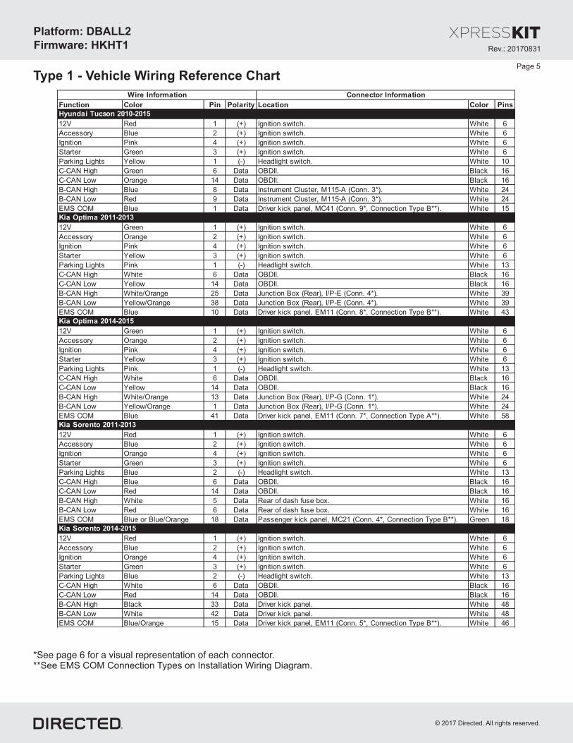
Type 1 - Vehicle Wiring Reference ChartPage 5
*See for a visual representation of each connector.page 6**See EMS COM Connection Types on Installation Wiring Diagram.
Function Color Pin Polarity Location Color Pins
12V Red 1 (+) Ignition switch. White 6
Accessory Blue 2 (+) Ignition switch. White 6
Ignition Pink 4 (+) Ignition switch. White 6
Starter Green 3 (+) Ignition switch. White 6
Parking Lights Yellow 1 (-) Headlight switch. White 10
C-CAN High Green 6 Data OBDII. Black 16
C-CAN Low Orange 14 Data OBDII. Black 16
B-CAN High Blue 8 Data Instrument Cluster, M115-A (Conn. 3*). White 24
B-CAN Low Red 9 Data Instrument Cluster, M115-A (Conn. 3*). White 24
EMS COM Blue 1 Data Driver kick panel, MC41 (Conn. 9*, Connection Type B**). White 15
12V Green 1 (+) Ignition switch. White 6
Accessory Orange 2 (+) Ignition switch. White 6
Ignition Pink 4 (+) Ignition switch. White 6
Starter Yellow 3 (+) Ignition switch. White 6
Parking Lights Pink 1 (-) Headlight switch. White 13
C-CAN High White 6 Data OBDII. Black 16
C-CAN Low Yellow 14 Data OBDII. Black 16
B-CAN High White/Orange 25 Data Junction Box (Rear), I/P-E (Conn. 4*). White 39
B-CAN Low Yellow/Orange 38 Data Junction Box (Rear), I/P-E (Conn. 4*). White 39
EMS COM Blue 10 Data Driver kick panel, EM11 (Conn. 8*, Connection Type B**). White 43
12V Green 1 (+) Ignition switch. White 6
Accessory Orange 2 (+) Ignition switch. White 6
Ignition Pink 4 (+) Ignition switch. White 6
Starter Yellow 3 (+) Ignition switch. White 6
Parking Lights Pink 1 (-) Headlight switch. White 13
C-CAN High White 6 Data OBDII. Black 16
C-CAN Low Yellow 14 Data OBDII. Black 16
B-CAN High White/Orange 13 Data Junction Box (Rear), I/P-G (Conn. 1*). White 24
B-CAN Low Yellow/Orange 1 Data Junction Box (Rear), I/P-G (Conn. 1*). White 24
EMS COM Blue 41 Data Driver kick panel, EM11 (Conn. 7*, Connection Type A**). White 58
12V Red 1 (+) Ignition switch. White 6
Accessory Blue 2 (+) Ignition switch. White 6
Ignition Orange 4 (+) Ignition switch. White 6
Starter Green 3 (+) Ignition switch. White 6
Parking Lights Blue 2 (-) Headlight switch. White 13
C-CAN High Blue 6 Data OBDII. Black 16
C-CAN Low Red 14 Data OBDII. Black 16
B-CAN High White 5 Data Rear of dash fuse box. White 16
B-CAN Low Red 6 Data Rear of dash fuse box. White 16
EMS COM Blue or Blue/Orange 18 Data Passenger kick panel, MC21 (Conn. 4*, Connection Type B**). Green 18
12V Red 1 (+) Ignition switch. White 6
Accessory Blue 2 (+) Ignition switch. White 6
Ignition Orange 4 (+) Ignition switch. White 6
Starter Green 3 (+) Ignition switch. White 6
Parking Lights Blue 2 (-) Headlight switch. White 13
C-CAN High White 6 Data OBDII. Black 16
C-CAN Low Red 14 Data OBDII. Black 16
B-CAN High Black 33 Data Driver kick panel. White 48
B-CAN Low White 42 Data Driver kick panel. White 48
EMS COM Blue/Orange 15 Data Driver kick panel, EM11 (Conn. 5*, Connection Type B**). White 46
Wire Information Connector Information
Kia Optima 2011-2013
Kia Optima 2014-2015
Kia Sorento 2011-2013
Kia Sorento 2014-2015
Hyundai Tucson 2010-2015

Rev.: 20 701 831
Platform: DBALL2
Firmware HKHT1:
© 201 Directed.7 All rights reserved.
Type 1 - Vehicle Wiring Reference ChartPage 6
3 - M115-A, White 24-pin
8 9
1 - I/P-G, White 24-pin
13
1
2 - I/P-F, White 24-pin
1211
5 - Black 20-pin
20
10
4 - Black 39-pin
38 34 3036 32 2837 33 2935 31
25 21 1723 19 1524 20 1622 18
12 8 410 6 211 7 39 5
39 27
26 14
13 1
All adapters are displayed from the wire side (unless specified otherwise).
6 - White 55-pin conn.
10
7 - White 58-pin conn.
8 - White 43-pin conn.
10
10 - Yellow 24-pin conn.
7
9 - Blue 15-pin conn.
1
*See for a visual representation of each connector.below**See EMS COM Connection Types on Installation Wiring Diagram.
12
41
Function Color Pin Polarity Location Color Pins
12V Red 1 (+) Ignition switch. White 6
Accessory Blue 2 (+) Ignition switch. White 6
Ignition Green 4 (+) Ignition switch. White 6
Starter White 3 (+) Ignition switch. White 6
Parking Lights Blue 1 (-) Headlight switch. White 13
C-CAN High Green 6 Data OBDII. Black 16
C-CAN Low Orange 14 Data OBDII. Black 16
B-CAN High Blue 20 Data Junction Box (Right), JM01 (Conn. 5*). Black 20
B-CAN Low Red 10 Data Junction Box (Right), JM01 (Conn. 5*). Black 20
EMS COM Blue 7 Data Passenger kick panel, MC11 (Conn. 10*, Connection Type A**). Yellow 24
Kia Sportage 2011-2016
Wire Information Connector Information

Rev.: 20 701 831
Platform: DBALL2
Firmware HKHT1:
© 201 Directed.7 All rights reserved.
Installation Type 2Page 7
Not required in D2D mode.
[1] EMS COM connections only needed if vehicle has a transponder immobilizer.
Rem
ote
Sta
rter
10
RF
Prog. Button
LED
4
XKD2D65TX
(-) Ground
RX
(+)12V
14
12
2
[1]EMS COM Data: 8Yellow:
[1]EMS COM Data: 9Orange :/Yellow
(-) Ground: 14Black:(-) Ground
(+) 12V: 13Red:(+) 12V
[1]EMS COM Data: 11Orange Black/ :
[1]EMS COM Data: 10Yellow/Black:
( ) Tach InputAC
( ) Tach Output: 5AC Violet/White:
Ignition, Accessory & Starter wireat ignition switch, 6-pin connector
(See section forReference Chartcorresponding pin and wire color
for your vehicle.)
1
4
2
5
3
6
10: (-) (Status) InputBlue/White: GWR
9: (+) Ignition InputPink:
(+) Ignition Input/Output
(-) (Status)GWR
(+) Starter Output
(+) 12V Input
(+) Accessory Output
EMS COM Connection Type( )See section for corresponding connection type, connector, pin and wire color according to your vehicle.Reference Chart
Connection ATYPE Connection BTYPE
CUT CUT
Yellow +Yellow/Black wire
from DBALL
Yellow +Yellow/Black wire
from DBALL
Orange/Yellow +Black wireOrange/
from DBALL
Orange/Yellow +Orange/Black wire
from DBALL
Connector Connector
Diagnostic onnectorC(connector side view)OBDII
1 8
169
C- High: pin 6CAN
C- Low: pin 14CAN
HS CAN Low: 4Tan:
HS CAN High: 3Tan/Black:
(-) Parking Lights Output
2DBALL
EMS COM connections only needed if vehicle has transponder/immobilizer.
Unless specified otherwise, all connectors are displayed from the wire side, with the exception of the diagnostic connector.OBDII
(-) Lock Output
(-) Unlock Output
(-) Driver Door Trigger Input
(+) Brake Input
(-) Trunk Release Output
Refer to the Vehicle wiringreference charts for wire andconnector details related tothe standard connections inthe vehicle.
(-) Ground

Rev.: 20 701 831
Platform: DBALL2
Firmware HKHT1:
© 201 Directed.7 All rights reserved.
Page 8
Type - Vehicle Wiring Reference Chart2
Function Color Pin Polarity Location Color Pins
12V Green 5 (+) Ignition switch. White 6
Accessory Orange 3 (+) Ignition switch. White 6
Ignition Pink 6 (+) Ignition switch. White 6
Starter White 1 (+) Ignition switch. White 6
C-CAN High Red 6 Data OBDII. Black 16
C-CAN Low Blue 14 Data OBDII. Black 16
Lock Blue 6 (-) Dash fuse box. White 16
Unlock Yellow/Black 16 (-) Dash fuse box. White 16
Brake Green 2 (+) Dash fuse box. Gray 18
Parking Lights Red or Pink/Black 10 (-) Drivers kick panel. Blue 20
EMS COM Blue/Black 15 Data Left of Junction Box, EM01 (Conn. 1*, Connection Type A**). Black 39
Drivers Door Green 2 (-) Drivers kick panel. Blue 42
12V Black 5 (+) Ignition switch. White 6
Accessory White or Orange 3 (+) Ignition switch. White 6
Ignition White/Blue or Blue 6 (+) Ignition switch. White 6
Starter Black/Yellow or White 1 (+) Ignition switch. White 6
Parking Lights Orange 8 (-) Headlight switch. White 14
C-CAN High White 6 Data OBDII. Black 16
C-CAN Low Yellow 14 Data OBDII. Black 16
Brake Black 34 (+) Drivers kick panel. Gray 39
Drivers Door Red 36 (-) Drivers kick panel. Gray 39
Lock Green 25 (-) Drivers kick panel. Gray 39
Unlock Yellow 39 (-) Drivers kick panel. Gray 39
Trunk Release White 5 (-) Drivers kick panel. Gray 40
EMS COM Blue/Black 15 Data Passenger kick panel, EM01 (Conn. 2*, Connection Type B**) Gray 39
12V White 5 (+) Ignition switch. White 6
Accessory Orange 3 (+) Ignition switch. White 6
Ignition Blue 6 (+) Ignition switch. White 6
Starter Pink 1 (+) Ignition switch. White 6
Parking Lights White 1 (-) Headlight switch. White 13
C-CAN High Red 6 Data OBDII. Black 16
C-CAN Low Blue 14 Data OBDII. Black 16
Brake Red/Orange 2 (+) Drivers kick panel. White 22
Drivers Door Orange 34 (-) Drivers kick panel. Blue 39
Lock Pink 36 (-) Drivers kick panel. Blue 39
Unlock Orange 39 (-) Drivers kick panel. Blue 39
Trunk Release Yellow 1 (-) Drivers kick panel. Blue 39
EMS COM Yellow 24 Data Passenger kick panel, EM01 (Conn. 1*, Connection Type A**) Blue 39
Brake Green 1 (+) Brake pedal switch. White 4
12V Pink 5 (+) Ignition switch. White 6
Accessory Orange 3 (+) Ignition switch. White 6
Ignition Blue 6 (+) Ignition switch. White 6
Starter Green 1 (+) Ignition switch. White 6
Drivers Door White 11 (-) Dash fuse box. White 12
C-CAN High White 6 Data OBDII. Black 16
C-CAN Low Yellow 14 Data OBDII. Black 16
Parking Lights Pink 14 (-) Headlight switch. White 18
Unlock Yellow/Black 3 (-) Drivers kick panel. Red 20
Trunk Release Yellow 1 (-) Drivers kick panel. Red 20
EMS COM Green 23 Data Driver kick panel, EM21 (Conn. 3*, Connection Type B**) White 33
Lock Pink/Black 2 (-) Drivers kick panel. Blue 39
Hyundai Sonata 2008-2010
Wire Information Connector Information
Hyundai Accent 2008-2011
Hyundai Elantra 2008-2010
Hyundai Genesis Coupe 2010-2012
*See for a visual representation of each connector.page 10**See EMS COM Connection Types on Installation Wiring Diagram.
Rev.: 20 701 831
Platform: DBALL2
Firmware HKHT1:
© 201 Directed.7 All rights reserved.
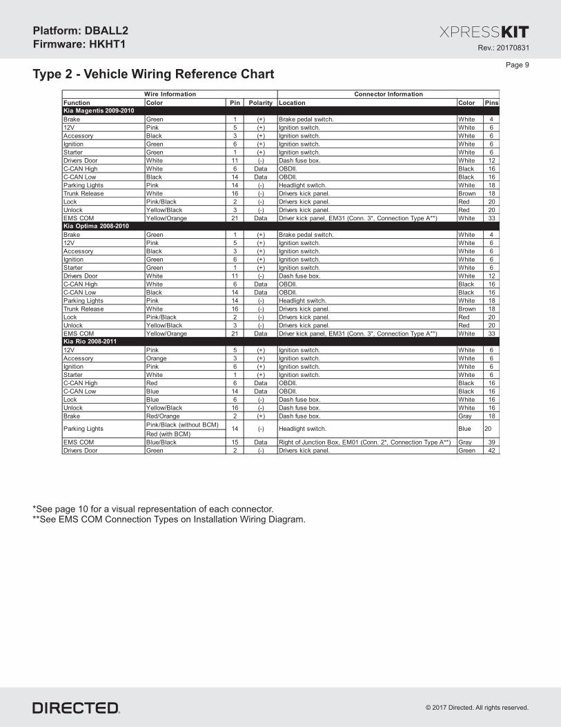
Type - Vehicle Wiring Reference Chart2Page 9
*See for a visual representation of each connector.page 10**See EMS COM Connection Types on Installation Wiring Diagram.
Function Color Pin Polarity Location Color Pins
Brake Green 1 (+) Brake pedal switch. White 4
12V Pink 5 (+) Ignition switch. White 6
Accessory Black 3 (+) Ignition switch. White 6
Ignition Green 6 (+) Ignition switch. White 6
Starter Green 1 (+) Ignition switch. White 6
Drivers Door White 11 (-) Dash fuse box. White 12
C-CAN High White 6 Data OBDII. Black 16
C-CAN Low Black 14 Data OBDII. Black 16
Parking Lights Pink 14 (-) Headlight switch. White 18
Trunk Release White 16 (-) Drivers kick panel. Brown 18
Lock Pink/Black 2 (-) Drivers kick panel. Red 20
Unlock Yellow/Black 3 (-) Drivers kick panel. Red 20
EMS COM Yellow/Orange 21 Data Driver kick panel, EM31 (Conn. 3*, Connection Type A**) White 33
12V Pink 5 (+) Ignition switch. White 6
Accessory Orange 3 (+) Ignition switch. White 6
Ignition Pink 6 (+) Ignition switch. White 6
Starter White 1 (+) Ignition switch. White 6
C-CAN High Red 6 Data OBDII. Black 16
C-CAN Low Blue 14 Data OBDII. Black 16
Lock Blue 6 (-) Dash fuse box. White 16
Unlock Yellow/Black 16 (-) Dash fuse box. White 16
Brake Red/Orange 2 (+) Dash fuse box. Gray 18
Pink/Black (without BCM)
Red (with BCM)
EMS COM Blue/Black 15 Data Right of Junction Box, EM01 (Conn. 2*, Connection Type A**) Gray 39
Drivers Door Green 2 (-) Drivers kick panel. Green 42
Wire Information Connector Information
Kia Optima 2008-2010
Kia Rio 2008-2011
Kia Magentis 2009-2010
14 (-) Headlight switch. Blue 20Parking Lights

Rev.: 20 701 831
Platform: DBALL2
Firmware HKHT1:
© 201 Directed.7 All rights reserved.
15 24
1 - Black 39-pin conn. 2 - Gray 39-pin conn.
15
3 - White 33-pin conn.
23
21
4 - Green 18-pin conn.
18
5 - Black 46-pin conn.
46
115
6 - Brown 23-pin conn.
14
7 - Yellow 24-pin conn.
7
Function Color Pin Polarity Location Color Pins
Brake Red 1 (+) Brake pedal switch. White 4
12V White 5 (+) Ignition switch. Black 6
Accessory Orange 3 (+) Ignition switch. Black 6
Ignition Blue 6 (+) Ignition switch. Black 6
Starter Green 1 (+) Ignition switch. Black 6
C-CAN High Orange 6 Data OBDII. Black 16
C-CAN Low Green 14 Data OBDII. Black 16
Drivers Door Orange 8 (-) Drivers kick panel. Blue 16
Lock Green 6 (-) Drivers kick panel. Blue 16
Unlock Blue 7 (-) Drivers kick panel. Blue 16
Parking Lights Brown 14 (-) Headlight switch. White 18
EMS COM Blue/Black 14 Data Passenger kick panel, MC01 (Conn. 6*, Connection Type B**) Brown 23
Brake Red 1 (+) Brake pedal switch. White 4
12V White 5 (+) Ignition switch. Black 6
Accessory Orange 3 (+) Ignition switch. Black 6
Ignition Blue 6 (+) Ignition switch. Black 6
Starter Green 1 (+) Ignition switch. Black 6
C-CAN High Orange 6 Data OBDII. Black 16
C-CAN Low Green 14 Data OBDII. Black 16
Drivers Door Orange 8 (-) Drivers kick panel. Blue 16
Lock Green 6 (-) Drivers kick panel. Blue 16
Unlock Blue 7 (-) Drivers kick panel. Blue 16
Parking Lights Brown 14 (-) Headlight switch. White 18
EMS COM Brown/Orange 7 Data Passenger kick panel, MC11 (Conn. 7*, Connection Type B**) Yellow 24
Wire Information Connector Information
Kia Sportage (4-cyl) 2008-2010
Kia Sportage (V6) 2008-2010
*See for a visual representation of each connector.below**See EMS COM Connection Types on Installation Wiring Diagram.
Page 10

Rev.: 20 701 831
Platform: DBALL2
Firmware HKHT1:
© 201 Directed.7 All rights reserved.
Installation Type 3Page 11
Rem
ote
Sta
rter
10
RF
Prog. Button
LED
4
XKD2D65TX
(-) Ground
RX
(+)12V
14
12
2
[1] EMS COM Data: 8Yellow:
[1] EMS COM Data: 9Orange :/Yellow
(-) Ground: 14Black:(-) Ground
(+) 12V: 13Red:(+) 12V
( ) Tach InputAC
(+) Brake Status
Ignition, Accessory & Starter wireat ignition switch, 6-pin connector
(See section forReference Chartcorresponding pin and wire color
for your vehicle.)
1
4
2
5
3
6
10: (-) (Status) InputBlue/White: GWR
9: (+) Ignition InputPink:
(+) Ignition Output
(-) (Status)GWR
(+) Starter Output
(+) 12V Input
(+) Accessory Output
EMS COM Connection Type( )See section for corresponding connection type, connector, pin and wire color for your vehicle.Reference Chart
Connection ATYPE Connection BTYPE
CUT CUT
Yellow +Yellow/Black wire
from DBALL
Yellow +Yellow/Black wire
from DBALL
Orange/Yellow +Black wireOrange/
from DBALL
Orange/Yellow +Black wireOrange/
from DBALL
Connector Connector
Not required in D2D mode.
HS CAN Low: 4Tan:
HS CAN High: 3Tan/Black:
Diagnostic onnectorC(connector side view)OBDII
1 8
169
[1] EMS COM Data: 11Orange Black/ :
[1] EMS COM Data: 10Yellow/Black:
( ) Tach Output: 5AC Violet/White:
(+) Brake Status Output: 6Gray:
2DBALL
EMS COM connections only needed if vehicle has transponder/immobilizer.
Unless specified otherwise, all connectors are displayed from the wire side, with the exception of the diagnostic connector.OBDII
C- High: pin 6CAN
C- Low: pin 14CAN
[1] EMS COM connections only needed if vehicle has a transponder immobilizer.
(-) Parking Lights Output
(-) Lock Output
(-) Unlock Output
(-) Driver Door Trigger Input
(-) Trunk Release Output
Refer to the Vehicle wiringreference charts for wire andconnector details related tothe standard connections inthe vehicle.
(-) Ground

Rev.: 20 701 831
Platform: DBALL2
Firmware HKHT1:
© 201 Directed.7 All rights reserved.
Page 12
Type - Vehicle Wiring Reference Chart3
Function Color Pin Polarity Location Color Pins
12V Green 1 (+) Ignition switch. Black 6
Accessory Orange 2 (+) Ignition switch. Black 6
Ignition Pink 4 (+) Ignition switch. Black 6
Starter White 3 (+) Ignition switch. Black 6
Parking Lights Pink/Black or Orange 7 (-) Headlight switch. White 14
C-CAN High Green 6 Data OBDII. Black 16
C-CAN Low Orange 14 Data OBDII. Black 16
EMS COM Blue/Orange 11 Data Left of Junction Box, EM01 (Conn. 1*, Connection Type B**). Black 21
Lock Brown (w/BCM) 15 (-) Drivers kick panel. (w/o BCM: add actuator in driver door). White 39
Unlock Gray (w/BCM) 13 (-) Drivers kick panel. (w/o BCM: add actuator in driver door). White 39
Drivers Door Brown/Orange 2 (-) Drivers kick panel. White 39
12V Orange 5 (+) Ignition switch. White 6
Accessory Pink 3 (+) Ignition switch. White 6
Ignition Blue 6 (+) Ignition switch. White 6
Starter White 1 (+) Ignition switch. White 6
Parking Lights Blue 8 (-) Headlight switch. White 14
C-CAN High White 6 Data OBDII. Black 16
C-CAN Low Yellow 14 Data OBDII. Black 16
Drivers Door Red 36 (-) Drivers kick panel. Gray 39
EMS COM Blue/Black 15 Data Passenger kick panel, EM11 (Conn. 2*, Connection Type B**). Gray 39
Lock Green 25 (-) Drivers kick panel. Gray 39
Unlock Yellow 39 (-) Drivers kick panel. Gray 39
Trunk Release White 5 (-) Drivers kick panel. Gray 39
12V Red 5 (+) Ignition switch. Black 6
Accessory Red or Blue 3 (+) Ignition switch. Black 6
Ignition Orange 6 (+) Ignition switch. Black 6
Starter Green 1 (+) Ignition switch. Black 6
C-CAN High Red/Black or Blue 6 Data OBDII. Black 16
C-CAN Low Red or Orange 14 Data OBDII. Black 16
Parking Lights Blue/Orange 14 (-) Headlight switch. White 18
EMS COMWhite/Orange or White
or Red19 Data Passenger kick panel, MC211 (Conn. 3*, Connection Type A**). Blue 24
Lock Blue/Black 18 (-) Drivers kick panel. Brown 24
Unlock Gray/Black 19 (-) Drivers kick panel. Brown 24
Drivers Door Green/Orange N/A (-) Drivers kick panel harness to rear. N/A N/A
12V Black 5 (+) Ignition switch. Black 6
Accessory Orange 3 (+) Ignition switch. Black 6
Ignition Blue 6 (+) Ignition switch. Black 6
Starter White 1 (+) Ignition switch. Black 6
C-CAN High Black 6 Data OBDII. Black 16
C-CAN Low White 14 Data OBDII. Black 16
Parking Lights Blue/Orange 14 (-) Headlight switch. White 18
Lock Blue/Black 18 (-) Drivers kick panel. Brown 24
Unlock Green/Orange 19 (-) Drivers kick panel. Brown 24
EMS COM Blue/Black 15 Data Passenger kick panel, MC12 (Conn. 2*, Connection Type B**) Gray 39
Drivers Door Green/Orange N/A (-) Drivers kick panel. N/A N/A
Kia Forte 2010-2013
Wire Information Connector Information
Hyundai Accent 2012-2016
Hyundai Elantra Touring 2009-2012
Hyundai Santa Fe 2008-2012

Rev.: 20 701 831
Platform: DBALL2
Firmware HKHT1:
© 201 Directed.7 All rights reserved.
4- Blue 42-pin conn.
18
3- Blue 24-pin conn.
19
1 - Black 21-pin conn.
11
5 - Blue 39-pin conn.
10
Page 13
All adapters are displayed from the wire side (unless specified otherwise).
2- Gray 39-pin conn.
15
Type - Vehicle Wiring Reference Chart3
Function Color Pin Polarity Location Color Pins
Kia Forte5 2011-2013
12V Black 5 (+) Ignition switch. Black 6
Accessory Orange 3 (+) Ignition switch. Black 6
Ignition Blue 6 (+) Ignition switch. Black 6
Starter White 1 (+) Ignition switch. Black 6
Parking Lights Orange 1 (-) Headlight switch. White 13
C-CAN High Black 6 Data OBDII. Black 16
C-CAN Low White 14 Data OBDII. Black 16
Trunk Release Blue/Black 2 (-) Rear of dash fuse box. White 18
EMS COM Blue/Black 15 Data Passenger kick panel, MC12 (Conn. 2*, Connection Type B**) Gray 39
Drivers Door Red 36 (-) Drivers kick panel. Gray 39
Lock Blue/Black 18 (-) Drivers kick panel. Gray 39
Unlock Green/Orange 19 (-) Drivers kick panel. Gray 39
12V Red or Pink 5 (+) Ignition switch. Black 6
Accessory White or Pink 3 (+) Ignition switch. Black 6
Ignition White/Blue or Blue 6 (+) Ignition switch. Black 6
Starter Black/Yellow or Green 1 (+) Ignition switch. Black 6
C-CAN High Red 6 Data OBDII. Black 16
C-CAN Low Blue 14 Data OBDII. Black 16
Trunk Release Blue/Orange 18 (-) BCM above brake pedal. White 22
Drivers Door Red 36 (-) BCM above brake pedal. White 22
Parking Lights Yellow 10 (-) BCM above brake pedal. White 26
Lock White 8 (-) Drivers kick panel. Gray 39
Unlock White/Black 9 (-) Drivers kick panel. Gray 39
EMS COM Brown 18 Data Driver kick panel, EM11 (Conn. 4*, Connection Type B**). Blue 42
12V White 5 (+) Ignition switch. Black 6
Accessory White 3 (+) Ignition switch. Black 6
Ignition Pink 6 (+) Ignition switch. Black 6
Starter Blue 1 (+) Ignition switch. Black 6
Parking Lights Pink 1 (-) Headlight switch. White 13
C-CAN High Red 6 Data OBDII. Black 16
C-CAN Low Blue 14 Data OBDII. Black 16
Trunk Release Pink 10 (-) Passenger kick panel. White 26
Drivers Door Green 9 (-) Passenger kick panel. White 26
EMS COM Blue/Black 110 Data Above driver kick panel, EM11 (Conn. 5* Connection Type B**). Blue 39
Lock Brown N/A (-) Drivers kick panel harness to rear. N/A N/A
Unlock Green N/A (-) Drivers kick panel harness to rear. N/A N/A
Kia Rondo 2008-2012
Kia Soul 2010-2013
Wire Information Connector Information

Rev.: 20 701 831
Platform: DBALL2
Firmware HKHT1:
© 201 Directed.7 All rights reserved.
Page 14
Type 1: Module Programming
2
5
3
4
The flashes orange slowly to indicate the bypass being programmedLED is( the not gAfter 2 minutes, if unit did program, the will start flashing reenLEDfor another 2 minutes maximum).
Turn the key to the position. The flashes green .ON LED once
Key OUT OF
F
START
IGN
Key IN OF
FSTART
ON
AC
C
&Flashes
Green x1
Turn the key to the position and remove it from ignition.OFF the
If the vehicle doesn’t have a transponder, the flashes red 3 times.LEDPress the programming button 5 times to skip the transponder programming.
The turns green for 3 seconds then shuts offLED ON solid.when the transponder will be programmed
If the transponder programming has been skipped,the turns solid orange for 3 seconds then shuts offLED ONwhen programming is done.
&OffGreen or Orange
Solid x3 sec
&
&
Press
5x
Press
5x
FlashesOrange
Flash Red 3xes
FlashesGreen
OR
You have successfully completed the module programming sequence.
Refer to the Diagnostics section for more information and for troubleshooting purposes.LED
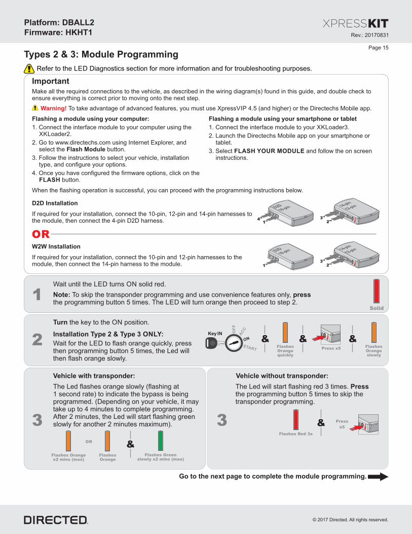
Important
Make all the required connections to the vehicle, as described in the wiring diagram(s) found in this guide, and double check toensure everything is correct prior to moving onto the next step.
Warning! To take advantage of advanced features, you must use Xpress 4.5 (and higher) or the Directechs Mobile app.VIP
When the flashing operation is successful, you can proceed with the programming instructions below.
OR
If required for your installation, connect the 10-pin, 12-pin and 14-pin harnesses tothe module, then connect the 4-pin D2D harness.
D2D Installation
W W Installation2
If required for your installation, connect the 10-pin and 12-pin harnesses to themodule, then connect the 14-pin harness to the module.
10-pinD2D
1st
12-pin14-pin
2nd
3rd
10-pinD2D
1st
4th
12-pin14-pin
2nd
3rd
1Solid
Wait until the LED turns solid red.ON
Note: To skip the transponder programming and use convenience features only, pressthe programming button 5 times. The will turn orange then proceed to step 2.LED
Flashing a module using your computer:
1. Connect the interface module to your computer using theXKLoader2.
2. Go to www.directechs.com using Internet Explorer, andselect the button.Flash Module
3. Follow the instructions to select your vehicle, installationtype, and configure your options.
4. Once you have configured the firmware options, click on theFLASH button.
Flashing a module using your smartphone or tablet
1. Connect the interface module to your oader3.XKL
2. Launch the Directechs Mobile app on your smartphone ortablet.
3. Select and follow the on screenFLASH YOUR MODULEinstructions.
Rev.: 20 701 831
Platform: DBALL2
Firmware HKHT1:
© 201 Directed.7 All rights reserved.
Vehicle without transponder:
2Key IN O
FF
START
ON
AC
C
& &FlashesOrangequickly
Page 15
Types 2 & 3: Module Programming
&
Press 5x
Press
5x
The Led flashes orange slowly (flashing at1 second rate) to indicate the bypass is beingprogrammed. (Depending on your vehicle, it maytake up to 4 minutes to complete programming.After 2 minutes, the Led will start flashing greenslowly for another 2 minutes maximum).
Flash Red 3xes
Turn the key to the position.ON
Installation Type 2 & Type 3 :ONLY
Wait for the to flash orange quickly, pressLEDnthe programming button 5 times, the Led will
then flash orange slowly.
FlashesOrangeslowly
&
Vehicle with transponder:
The Led will start flashing red 3 times. Pressthe programming button 5 times to skip thetransponder programming.
3 3
FlashesOrange
Flash Greenesslowly x2 mins (max)
OR &Flash Orangeesx2 mins (max)
Refer to the Diagnostics section for more information and for troubleshooting purposes.LED
Go to the next page t complete the module programming.o
Important
Make all the required connections to the vehicle, as described in the wiring diagram(s) found in this guide, and double check toensure everything is correct prior to moving onto the next step.
Warning! To take advantage of advanced features, you must use Xpress 4.5 (and higher) or the Directechs Mobile app.VIP
When the flashing operation is successful, you can proceed with the programming instructions below.
OR
If required for your installation, connect the 10-pin, 12-pin and 14-pin harnesses tothe module, then connect the 4-pin D2D harness.
D2D Installation
W W Installation2
If required for your installation, connect the 10-pin and 12-pin harnesses to themodule, then connect the 14-pin harness to the module.
10-pinD2D
1st
12-pin14-pin
2nd
3rd
10-pinD2D
1st
4th
12-pin14-pin
2nd
3rd
1Solid
Wait until the LED turns solid red.ON
Note: pressTo skip the transponder programming and use convenience features only,the programming button 5 times. The will turn orange then proceed to step 2.LED
Flashing a module using your computer:
1. Connect the interface module to your computer using theXKLoader2.
2. Go to www.directechs.com using Internet Explorer, andselect the button.Flash Module
3. Follow the instructions to select your vehicle, installationtype, and configure your options.
4. Once you have configured the firmware options, click on theFLASH button.
Flashing a module using your smartphone or tablet
1. Connect the interface module to your oader3.XKL
2. Launch the Directechs Mobile app on your smartphone ortablet.
3. Select and follow the on screenFLASH YOUR MODULEinstructions.
Rev.: 20 701 831
Platform: DBALL2
Firmware HKHT1:
© 201 Directed.7 All rights reserved.
2Solid
&Solid Flashes
&Release
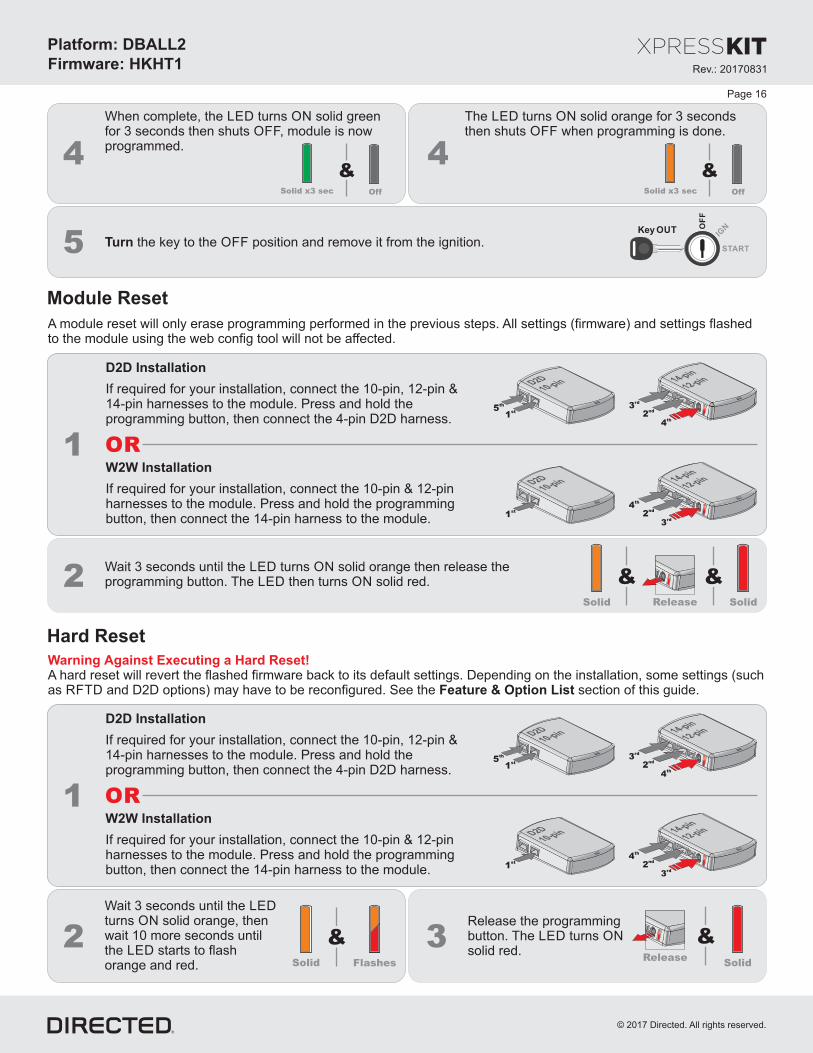
3Wait 3 seconds until the LEDturns solid ,ON orange thenw 10 more secondsait untilthe LED starts to flashorange red.and
Release the programmingbutton. The turnsLED ONsolid red.
1 OR
If required for your installation, c , &onnect the 10-pin 12-pin14-pin harnesses to the module Press hold the. andp , then connect the 4-pin D2D harness.rogramming button
D2D Installation
If required for your installation, connect the 10-pin & 12-pinharnesses to the module Press hold the rogramming. and pbutton, then connect the 14-pin harness to the module.
W2W Installation
10-pinD2D
1st
12-pin14-pin
2nd
4th
3rd
10-pinD2D
1st
5th
12-pin14-pin
2nd
3rd
4th
Module Reset
Hard Reset
2 & &Solid SolidRelease
Wait 3 seconds until the orange then release theLED turns solidONp The then turns solid red.rogramming button. LED ON
1 OR
If required for your installation, c , &onnect the 10-pin 12-pin14-pin harnesses to the module Press hold the. andp , then connect the 4-pin D2D harness.rogramming button
D2D Installation
If required for your installation, connect the 10-pin & 12-pinharnesses to the module Press hold the rogramming. and pbutton, then connect the 14-pin harness to the module.
W2W Installation
10-pinD2D
1st
12-pin14-pin
2nd
4th
3rd
10-pinD2D
1st
5th
12-pin14-pin
2nd
3rd
4th
A module reset will only erase programming performed in the previous steps. All settings (firmware) and settings flashedto the module using the web config tool will not be affected.
Warning gainst xecuting a Hard Reset!A EA hard reset will revert the flashed firmware back to its default settings. Depending on the installation, some settings (suchas and D2D options) may have to be reconfigured. See the section of this guide.RFTD Feature & Option List
5 Turn the key to the position and remove it from the ignition.OFFKey OUT O
FF
START
IGN
&OffSolid x3 sec
4 4
When complete, the turns solid greenLED ONfor 3 seconds then shuts , module is nowOFFprogrammed.
The turns solid orange for 3 secondsLED ONthen shuts when programming is done.OFF
&OffSolid x3 sec
Page 16

Rev.: 20 701 831
Platform: DBALL2
Firmware HKHT1:
© 201 Directed.7 All rights reserved.
Feature & Option List
To enter feature programming routine- Turn t , thenhe ignition .ON OFF- Within 5 seconds, press and the rogramming button turns after 3 seconds . Release theHOLD LED ONp until the orange ( )
Programming button.- The to indicate the feature number is 1. After a short delay, the flashes rapidly to indicateLED LEDwill flash green once slowly red
the current option of feature 1 .(i.e. 1x green followed by 1x red indicates feature 1 is set to option 1) The flashing sequence willrepeat until .a new command is entered
Changing feature options- Press the arm or disarm button on aftermarket transmitter to change the option of the selected feature.lock/ unlock/- The flashes rapidly the number of times equal to the current option number. After a short delay, the flashes greenLED LEDred
slowly the number of times to indicate the current feature. repeat until .The flashing sequence will a new command is entered
Accessing another feature- Press and release the programming button a number of times to advance from the current feature to the next desired feature.- The flashes green slowly the number of times equal to the feature number. After a short delay, the flashes red rapidly toLED LED
indicate the current option of the current feature. repeat until .The flashing sequence will a new command is entered
When the maximum number of features or options is reached, the will start flashing again from the first feature orLEDoption.
Once a feature is programmed- Other features can be programmed.- The feature programming can be exited.
Exiting feature programming- No activity for 30 seconds; after 30 seconds, the will turn orange for 2 seconds to confirm the end of the programmingLED ON
sequence.OR
- Press and the programming button for 3 seconds. After 3 seconds, the will turn orange for 2 seconds to confirmHOLD LED ONthe end of the programming sequence.
Feature ProgrammingProgramming
Button
Page 17
It is recommended to configure all features and options listed below thethe using configuration tool found on the moduleflashing page on www. .comdirectechs . The web offers more options; however, manual configuration of the features is possibleusing the information on this page.
Feat. Operation Flashes/Option Description
1. No RF Output* Module is connected to a remote starter using a standard installation.
2. RFTD Output Module is connected to an XL202 using an RSR or RXT installation (when available).
3. SmartStart Module is connected to SmartStart using an RSR or RXT installation (when available).
1. Driver priority* Unlocks only the driver door on first press and unlocks all doors on a second press within 5 seconds.
2. All Unlocks all doors on first press.
1. DisabledThe OEM alarm will not be controlled by DBALL upon remote start. No disarm or arm command will be
executed at the beginning or end of the sequence; it must be controlled by the Remote Starter.
2. SafelockSmart OEM Alarm Control will behave like a standard Safelock feature on a remote starter. It will unlock at
the beginning of the sequence, and relock after start and shutdown.
3. Enabled*
Smart OEM Alarm Control will synchronize with the OEM alarm so that it will disarm and rearm the vehicle
in the remote start sequence, only when required. The reason for this is, factory alarm control must often be
done by lock or unlock operation. This could create unnecessary actions on door lock modules, such as the
horn to honk. When possible, Smart OEM Alarm Control will monitor the alarm and door lock status to
detect if the disarm or rearm is required. If the vehicle is unlocked or is not equipped with factory alarm, the
disarm/rearm will not be executed. Smart OEM Alarm Control will also monitor the remote starter actions so
that the factory alarm control is not done twice. A remote starter, for which the Safelock feature is active,
will work perfectly with this option and will make it invisible to the user.
2
* Default Option
Smart OEM Alarm
Control3
RF Output1
Unlock Driver Priority
Rev.: 20 701 831
Platform: DBALL2
Firmware HKHT1:
© 201 Directed.7 All rights reserved.
Page 18
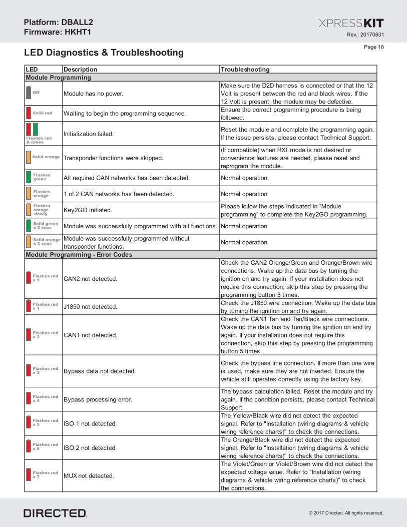
LED Description Troubleshooting
Module has no power.
Make sure the D2D harness is connected or that the 12
Volt is present between the red and black wires. If the
12 Volt is present, the module may be defective.
Waiting to begin the programming sequence.Ensure the correct programming procedure is being
followed.
Initialization failed.Reset the module and complete the programming again.
If the issue persists, please contact Technical Support.
Transponder functions were skipped.
(If compatible) when RXT mode is not desired or
convenience features are needed, please reset and
reprogram the module.
All required CAN networks has been detected. Normal operation.
1 of 2 CAN networks has been detected. Normal operation
Key2GO initiated.Please follow the steps indicated in “Module
programming” to complete the Key2GO programming.
Module was successfully programmed with all functions. Normal operation
Module was successfully programmed without
transponder functions.Normal operation.
CAN2 not detected.
Check the CAN2 Orange/Green and Orange/Brown wire
connections. Wake up the data bus by turning the
ignition on and try again. If your installation does not
require this connection, skip this step by pressing the
programming button 5 times.
J1850 not detected.Check the J1850 wire connection. Wake up the data bus
by turning the ignition on and try again.
CAN1 not detected.
Check the CAN1 Tan and Tan/Black wire connections.
Wake up the data bus by turning the ignition on and try
again. If your installation does not require this
connection, skip this step by pressing the programming
button 5 times.
Bypass data not detected.
Check the bypass line connection. If more than one wire
is used, make sure they are not inverted. Ensure the
vehicle still operates correctly using the factory key.
Bypass processing error.
The bypass calculation failed. Reset the module and try
again. If the condition persists, please contact Technical
Support.
ISO 1 not detected.
The Yellow/Black wire did not detect the expected
signal. Refer to "Installation (wiring diagrams & vehicle
wiring reference charts)" to check the connections.
ISO 2 not detected.
The Orange/Black wire did not detect the expected
signal. Refer to "Installation (wiring diagrams & vehicle
wiring reference charts)" to check the connections.
MUX not detected.
The Violet/Green or Violet/Brown wire did not detect the
expected voltage value. Refer to "Installation (wiring
diagrams & vehicle wiring reference charts)" to check
the connections.
Module Programming
Module Programming - Error Codes
Solid red
Flashes redx 1
Flashes redx 1
Flashes redx 2
Flashes redx 3
Flashes redx 4
Flashes redx 5
Flashes redx 6
Flashes redx 7
Solid greenx 3 secs
Flashesgreen
Solid orange
Flashes red& green
Off
Flashesorange
Flashesorangeslowly
Solid orangex 3 secs
LED Diagnostics & Troubleshooting
Rev.: 20 701 831
Platform: DBALL2
Firmware HKHT1:
© 201 Directed.7 All rights reserved.
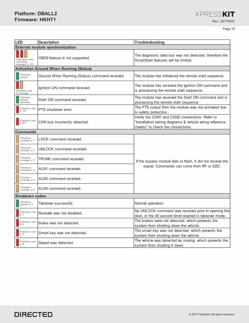
LED Description Troubleshooting
OBDII feature is not supported.The diagnostic data bus was not detected, therefore the
SmartStart features will be limited.
Ground When Running (Status) command received. The module has initialized the remote start sequence.
Ignition ON command received.The module has received the Ignition ON command and
is processing the remote start sequence.
Start ON command received.The module has received the Start ON command and is
processing the remote start sequence.
PTS shutdown error.The PTS output from the module was not activated due
to safety protection.
CAN bus incorrectly detected.
Verify the CAN1 and CAN2 connections. Refer to
“Installation (wiring diagrams & vehicle wiring reference
charts)” to check the connections.
LOCK command received.
UNLOCK command received.
TRUNK command received.
AUX1 command received.
AUX2 command received.
AUX3 command received.
Takeover successful. Normal operation.
Runsafe was not disabled.No UNLOCK command was received prior to opening the
door, or the 45 second timer expired in takeover mode.
Brake was not detected.The brakes were not detected, which prevents the
system from shutting down the vehicle.
Smart key was not detected.The smart key was not detected, which prevents the
system from shutting down the vehicle.
Speed was detected.The vehicle was detected as moving, which prevents the
system from shutting it down.
External module synchronization
Commands
Activation Ground When Running (Status)
If the bypass module fails to flash, it did not receive the
signal. Commands can come from RF or D2D.
Shutdown codes
(Flashes red,red thenorange) x 10
Flashes red& orange
Flashes redx 21
Flashes redx 2
Flashes redx 4
Flashes redx 10
Flashes redx 1
Flashes redx 3
Flashesgreen
Flashesgreenquickly
Flashesgreen x 1
Flashesorange x 1
Flashesorange x 2
Flashesorange x 3
Flashesorange x 5
Flashesorange x 4
Flashesorange x 6
Page 19

Rev.: 20 701 831
Platform: DBALL2
Firmware HKHT1:
© 201 Directed.7 All rights reserved.
For a period of from the date of purchase of a Directed Electronics remote start or security product, DirectedONE YEARElectronics. (“ ”) promises to the original purchaser, to repair or replace with a comparable reconditioned piece, theDIRECTEDsecurity or remote start accessory piece (hereinafter the “Part”), which proves to be defective in workmanship or materialunder normal use, provided the following conditions are met: the Part was purchased from an authorized dealer;DIRECTEDand the Part is returned to , postage prepaid, along with a clear, legible copy of the receipt or bill of sale bearing theDIRECTEDfollowing information: consumer’s name, address, telephone number, the authorized licensed dealer’s name and completeproduct and Part description.
This warranty is nontransferable and is automatically void if the Part has been modified or used in a manner contrary to itsintended purpose or the Part has been damaged by accident, unreasonable use, neglect, improper service, installation orother causes not arising out of defect in materials or construction.
TO THE MAXIMUM EXTENT ALLOWED BY LAW EXCEPT AS STATED ABOVE ALL WARRANTIES INCLUDING, , ,BUT NOT LIMITED TO EXPRESS WARRANTY IMPLIED WARRANTY WARRANTY OF MERCHANTABILITY, , ,FITNESS FOR PARTICULAR PURPOSE AND WARRANTY OF NONINFRINGEMENT OF INTELLECTUALPROPERTY ARE EXPRESSLY EXCLUDED AND DIRECTED NEITHER ASSUMES NOR AUTHORIZES ANY, ;PERSON OR ENTITY TO ASSUME FOR IT ANY DUTY OBLIGATION OR LIABILITY IN CONNECTION WITH ITS,PRODUCTS DIRECTED HEREBY DISCLAIMS AND HAS ABSOLUTELY NO LIABILITY FOR ANY AND ALLACTS OF.THIRD PARTIES INCLUDING DEALERS OR INSTALLERS DIRECTED IS NOT OFFERING GUARANTEE OR. AINSURANCE AGAINST VANDALISM DAMAGE OR THEFT OF THE AUTOMOBILE ITS PARTS OR CONTENTS, , , ,AND DIRECTED HEREBY DISCLAIMS ANY LIABILITY WHATSOEVER INCLUDING WITHOUT LIMITATION, ,LIABILITY FOR THEFT DAMAGE OR VANDALISM IN THE EVENT OF CLAIM OR DISPUTE INVOLVING, , . A ADIRECTED OR ITS SUBSIDIARY THE PROPER VENUE SHALL BE SAN DIEGO COUNTY IN THE STATE OF,CALIFORNIA CALIFORNIA STATE LAWS AND APPLICABLE FEDERAL LAWS SHALL APPLY AND GOVERN THE.DISPUTE THE MAXIMUM RECOVERY UNDER ANY CLAIM AGAINST DIRECTED SHALL BE STRICTLY LIMITED.TO THE AUTHORIZED DIRECTED DEALER PURCHASE PRICE OF THE PART DIRECTED SHALL NOT BE’S .RESPONSIBLE FOR ANY DAMAGES WHATSOEVER INCLUDING BUT NOT LIMITED TO ANY CONSEQUENTIAL, ,DAMAGES INCIDENTAL DAMAGES DAMAGES FOR THE LOSS OF TIME LOSS OF EARNINGS COMMERCIAL, , , ,LOSS LOSS OF ECONOMIC OPPORTUNITY AND THE LIKE NOTWITHSTANDING THE ABOVE THE, . ,MANUFACTURER DOES OFFER LIMITED WARRANTY TO REPLACE OR REPAIR AT DIRECTED OPTION THEA ’SPARTAS DESCRIBED ABOVE.
This warranty only covers Parts sold within the United States ofAmerica and Canada. Parts sold outside of the United States ofAmerica or Canada are sold “ - ” and shall have , express or implied. Some states do not allow limitationsAS IS NO WARRANTYon how long an implied warranty will last or the exclusion or limitation of incidental or consequential damages. This warrantygives you specific legal rights and you may also have other rights that vary from State to State. does not and hasDIRECTEDnot authorized any person or entity to create for it any other obligation, promise, duty or obligation in connection with this Part.For further details relating to warranty information of Directed products, please visit the support section of ’sDIRECTEDwebsite at: www.directed.com
920-10012-01 2013-07
This Interface kit / Data Bus Interface part has been tested on the listed vehicles. Other vehicles will be added to the selectvehicle list upon completion of compatibility testing. Visit website for latest vehicle application guide. : Under noDISCLAIMERcircumstances shall the manufacturer or the distributors of the bypass kit / data bus interface part(s) be held liable for anyconsequential damages sustained in connection with the part(s) installation. The manufacturer and it’s distributors will not, norwill they authorize any representative or any other individual to assume obligation or liability in relation to the interface kit / databus interface part(s) other than its replacement. N.B.: Under no circumstances shall the manufacturer and distributors of thisproduct be liable for consequential damages sustained in connection with this product and neither assumes nor authorizesany representative or other person to assume for it any obligation or liability other than the replacement of this product only.
Protected by U.S. Patents: 5,719,551; 6,011,460 B1 *; 6,243,004 B1; 6,249,216 B1; 6,275,147 B1; 6,297,731 B1; 6,346,876B1; 6,392,534 B1; 6,529,124 B2; 6,696,927 B2; 6,756,885 B1; 6,756,886 B2; 6,771,167 B1; 6,812,829 B1; 6,924,750 B1;7,010,402 B1; 7,015,830 B1; 7,031,826 B1; 7,046,126 B1; 7,061,137 B1; 7,068,153 B1; 7,205,679 B1; Cdn. Patent:2,320,248; 2,414,991; 2,415,011; 2,415,023; 2,415,027; 2,415,038; 2,415,041; 2,420,947; 2,426,670; 2,454,089; EuropeanPatent: 1,053,128; Pat. Pending: 2,291,306. Made in Canada.
Limited Consumer WarrantyOne YearPage 20

Quick Reference GuideDBALL2-HKHT1
© 2017 Directed. All rights reserved.
Notes
Button(s) Actions
Press & hold for 1 second to lock.
Press & hold for 1 second to unlock.
Press & hold for 1 second to remote
start.
Press & hold for 5 seconds to activate
the trunk release (optional).
Press once, then to activate the
rear hatch/tail glass release (optional).*
Press 3 times, then to activate
the panic mode.
Press once, then to reset the
remote starter runtime.
List of Available Commands
x1 +
x3 +
x1 +
* This output is configurable. see your authorized installation center for more information.
Note that the information below is for Viper, Clifford and Python models. Icons and commands may differ depending on the remote brand and model purchased. Refer to your authorized installation center for more information.
�佒L �� A�
佃 呅剆
G畩摥猠�慮�楳�楳灯湩扬敳甠睷w�摡瑡汩湫�潭
块 偐佒
W��T�����单 T A畴潭潴楶攠D慴愠S潬畴楯湳 I湣����
Hyundai Genesis Sedan with Smart Key
©2010DirectedElectronics.Allrightsreserved.
("Push-button Start")
Hyundai proximity key solution