Embed Size (px)
Citation preview
Stromberg Carlson Products, Inc. 2323 Traversefield Drive Traverse City, Michigan 49686 231‐947‐8600 ext. 108 for Customer Service [email protected]
1
PLATFORM BIKE CARRIER
Model BC‐204
MAXIMUM LOADING CAPACITY ‐ 160 LBS
Recommended Tools for Assembly:
Open Wrench
(1pc)
Size=17mm
Open Wrench
(2pc)
Size=24mm
Open Wrench
(1pc)
Size=19mm

Stromberg Carlson Products, Inc. 2323 Traversefield Drive Traverse City, Michigan 49686 231‐947‐8600 ext. 108 for Customer Service [email protected]
2
Assembly Instructions
STEP 1 Assemble the primary frame by connecting the Short Support Base Assembly (part #1) and (2) Horizontal Arms
(part #2), using (2) 5/16" knob, (4) 5/16" flat washer , (2) 5/16" spring washer, (2) 5/16" hexagon bolt, (2) M10 Carriage bolts
and (2) M10 Locknuts (parts #3, #4, #5,#6,#27& #28). See FIG. 1
FIG. 1
STEP 2 Place Vertical Arm (part #7) into the Short Support Base Assembly by using M10 Carriage Bolt and M10 Locknut
(parts #27 & #28). With the Vertical Tube in a vertical position, insert the 5/16" hexagon bolt (part #6), through the 5/16" flat
washer(part #4) ,the 5/16" spring washer(part #5) and the 5/16" flat washer(part #4) ,tighten with 5/16" knob (part #3) .See
FIG. 2
FIG. 2
NOTICE:
The sliding teeth face
this direction
Stromberg Carlson Products, Inc. 2323 Traversefield Drive Traverse City, Michigan 49686 231‐947‐8600 ext. 108 for Customer Service [email protected]
3
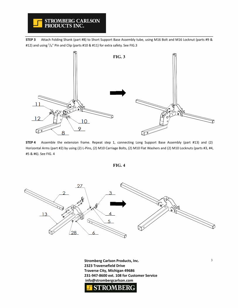
STEP 3 Attach Folding Shank (part #8) to Short Support Base Assembly tube, using M16 Bolt and M16 Locknut (parts #9 &
#12) and using 5/8” Pin and Clip (parts #10 & #11) for extra safety. See FIG.3
FIG. 3
STEP 4 Assemble the extension frame. Repeat step 1, connecting Long Support Base Assembly (part #13) and (2)
Horizontal Arms (part #2) by using (2) L‐Pins, (2) M10 Carriage Bolts, (2) M10 Flat Washers and (2) M10 Locknuts (parts #3, #4,
#5 & #6). See FIG. 4
FIG. 4

Stromberg Carlson Products, Inc. 2323 Traversefield Drive Traverse City, Michigan 49686 231‐947‐8600 ext. 108 for Customer Service [email protected]
4
STEP 5 Repeat step 2, placing Vertical Arm (part #7) on the Long Support Base, using 5/16" knob, (2)5/16" flat washer,
5/16" spring washer, 5/16" hexagon bolt, M10 Carriage Bolt and M10 Locknut (parts #3, #4, #5, #6, #27 & #28). See FIG. 5
FIG. 5
STEP 6 Insert the Long Support Base (part #1) into the Short Support Base (part #13), controlling the height by inserting
the Short Stabilizing Pin, 1/2” Flat Washer and 1/2” Spring Washer (parts # 14, #15 & #16). Insert Clip (part #11). See FIG. 6
FIG. 6
NOTICE:
The sliding teeth face
this direction

Stromberg Carlson Products, Inc. 2323 Traversefield Drive Traverse City, Michigan 49686 231‐947‐8600 ext. 108 for Customer Service [email protected]
5
STEP 7 Slide the Left and Right Cradle Assemblies (parts #17 & #18) onto the Horizontal Arms. Release the knob of the left
and right cradle. The knob should be facing up and the loop end of cradle should be facing outward and upward. Insert the
cradles in sequence as shown below in Fig 7. After all 4 cradles are on the Horizontal Arms, tighten. See FIG. 7
FIG. 7
STEP 8 Install the (2) Long J‐Hook Assemblies (part #19) and (2) Short J‐Hook Assemblies (part #20) onto the Vertical Arm,
then tighten the (2) Eyebolts (part #21). Put the Reflector (part #22) in the hole of the square tube. See FIG. 8
NOTE: Eyebolt provided for use with customer‐provided bike cable and lock, to prevent bicycle loss.
FIG. 8
Stromberg Carlson Products, Inc. 2323 Traversefield Drive Traverse City, Michigan 49686 231‐947‐8600 ext. 108 for Customer Service [email protected]
6
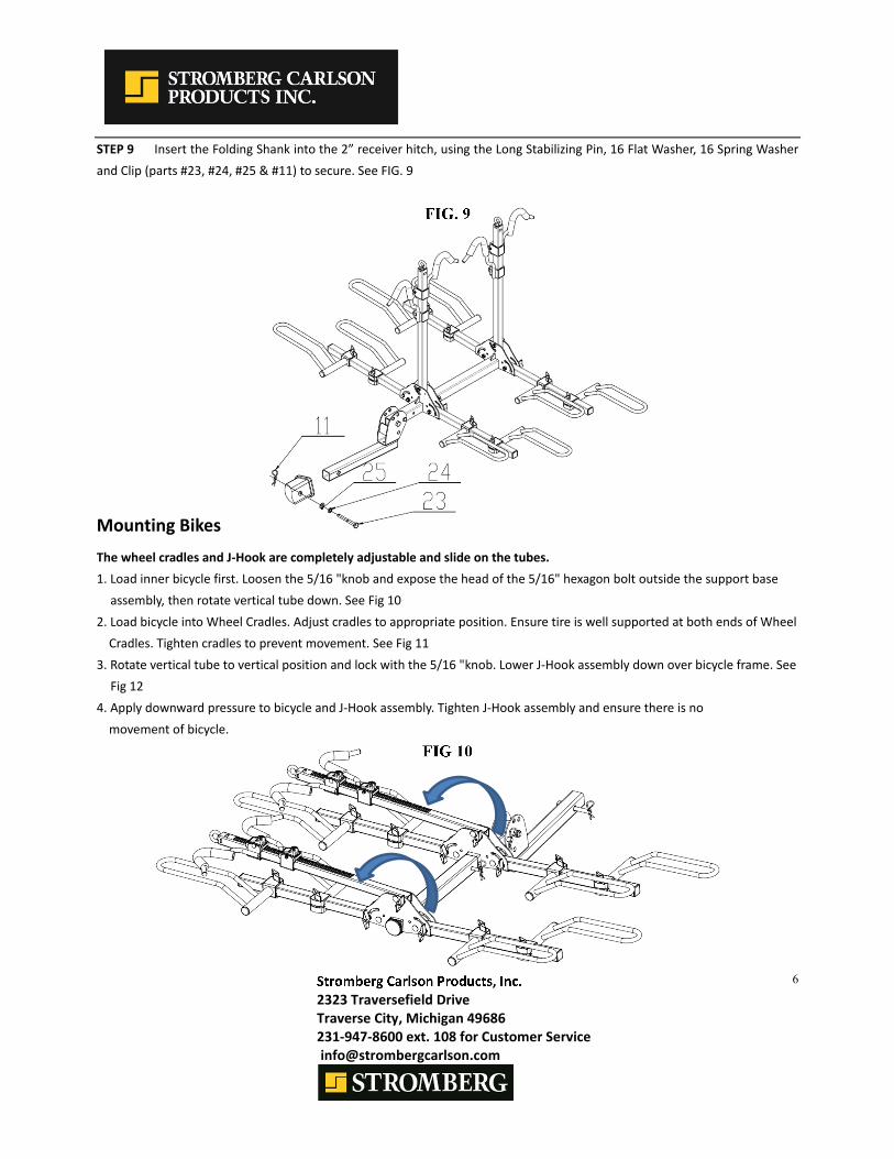
STEP 9 Insert the Folding Shank into the 2” receiver hitch, using the Long Stabilizing Pin, 16 Flat Washer, 16 Spring Washer
and Clip (parts #23, #24, #25 & #11) to secure. See FIG. 9
FIG. 9
Mounting Bikes
The wheel cradles and J‐Hook are completely adjustable and slide on the tubes.
1. Load inner bicycle first. Loosen the 5/16 "knob and expose the head of the 5/16" hexagon bolt outside the support base
assembly, then rotate vertical tube down. See Fig 10
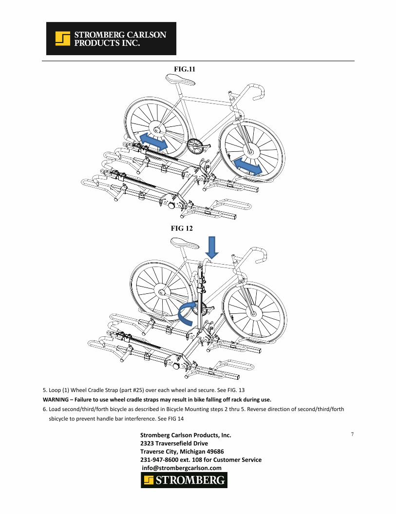
2. Load bicycle into Wheel Cradles. Adjust cradles to appropriate position. Ensure tire is well supported at both ends of Wheel
Cradles. Tighten cradles to prevent movement. See Fig 11
3. Rotate vertical tube to vertical position and lock with the 5/16 "knob. Lower J‐Hook assembly down over bicycle frame. See
Fig 12
4. Apply downward pressure to bicycle and J‐Hook assembly. Tighten J‐Hook assembly and ensure there is no
movement of bicycle.
FIG 10
Stromberg Carlson Products, Inc. 2323 Traversefield Drive Traverse City, Michigan 49686 231‐947‐8600 ext. 108 for Customer Service [email protected]
7
FIG 12
5. Loop (1) Wheel Cradle Strap (part #25) over each wheel and secure. See FIG. 13
WARNING – Failure to use wheel cradle straps may result in bike falling off rack during use.
6. Load second/third/forth bicycle as described in Bicycle Mounting steps 2 thru 5. Reverse direction of second/third/forth
sbicycle to prevent handle bar interference. See FIG 14
FIG.11

Stromberg Carlson Products, Inc. 2323 Traversefield Drive Traverse City, Michigan 49686 231‐947‐8600 ext. 108 for Customer Service [email protected]
8
Tilt Down Feature
Do not place bikes on the wheel cradle when operating the tilt down feature. For access to the rear of vehicle, remove 5/8” Pin
and allow the rack to tilt downward. For safety, be sure to securely hold the bike rack while the pin is out. See FIG. 15
FIG. 15
Storage Feature
Loosen the 5/16" knob, rotate the support tube to the vertical states, and then tighten the 5/16" knob. See FIG. 16
FIG. 16
FIG.13 FIG.14
Wheel Cradle strap
Stromberg Carlson Products, Inc. 2323 Traversefield Drive Traverse City, Michigan 49686 231‐947‐8600 ext. 108 for Customer Service [email protected]
9
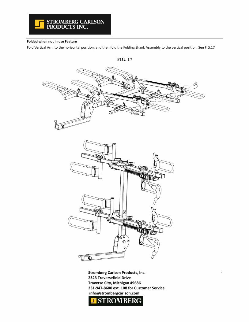
Folded when not in use Feature
Fold Vertical Arm to the horizontal position, and then fold the Folding Shank Assembly to the vertical position. See FIG.17
FIG. 17

Stromberg Carlson Products, Inc. 2323 Traversefield Drive Traverse City, Michigan 49686 231‐947‐8600 ext. 108 for Customer Service [email protected]
10
Assembly Diagram
Part List
Part# Description Qty Part# Description Qty
1 Short Support Base Assembly 1 16 1/2” Flat Washer 1
2 Horizontal Arm 4 17 Left Cradle Assembly 4
3 5/16" Knob 6 18 Right Cradle Assembly 4
4 5/16" Flat Washer 12 19 Long J‐Hook Assembly 2
5 5/16" Spring Washer 6 20 Short J‐Hook Assembly 2
6 5/16" Hexagon Bolt 6 21 Eyebolt 2
7 Vertical Arm 2 22 Reflector 1
8 Folding Shank 1 23 Long Stabilizing Pin 1
9 M16 Bolt 1 24 16 Spring Washer 1
10 5/8”Pin 1 25 16 Flat Washer 1
11 Clip 3 26 Wheel Cradle Strap 8
12 M16 Locknut 1 27 M10 Carriage Bolt 6
13 Long Support Base Assembly 1 28 M10 Locknut 6
14 Short Stabilizing Pin 1 29 Circular Key 1
15 1/2” Spring Washer 1