Embed Size (px)
DESCRIPTION
Reference book for engineers and designers regarding design of plastics.
Citation preview
CHAPTER CHAPTER NAME
1. Plastics
History
Composition
Polymerization process
Composition
Properties of plastics
Common plastics & uses
Different manufacturing processes for Plastics:
• Injection Moulding.
• Compression Moulding.
• Blow Moulding.
• Compression Moulding.
• Plastics Extrusion.
• Thermoforming.
• Slush Moulding.
• Transfer moulding.
• Calendaring.
Gate type
Design Rules For Plastic Parts:
• Maximum wall thickness
• Corners
• Draft
• Ribs
• Bosses
• Undercuts
• Threads
TYPICAL NOMINAL THICKNESS FOR VARIOUS
CLASSES OF THERMOPLASTICS
DEFECTS of PLASTICS
Welding Techniques
Hot gas welding
Heat seal
Freehand welding
Speed tip welding
Extrusion welding
Contact welding

Hot plate welding
High frequency welding
Injection welding
Ultrasonic welding
Friction welding
Spin welding
Laser welding
Transparent Laser Plastic Welding
Solvent welding
Welding rod
PLASTICS • Growing demand in the automotive sector
Plastics In Automotive Markets Today
Abbreviations
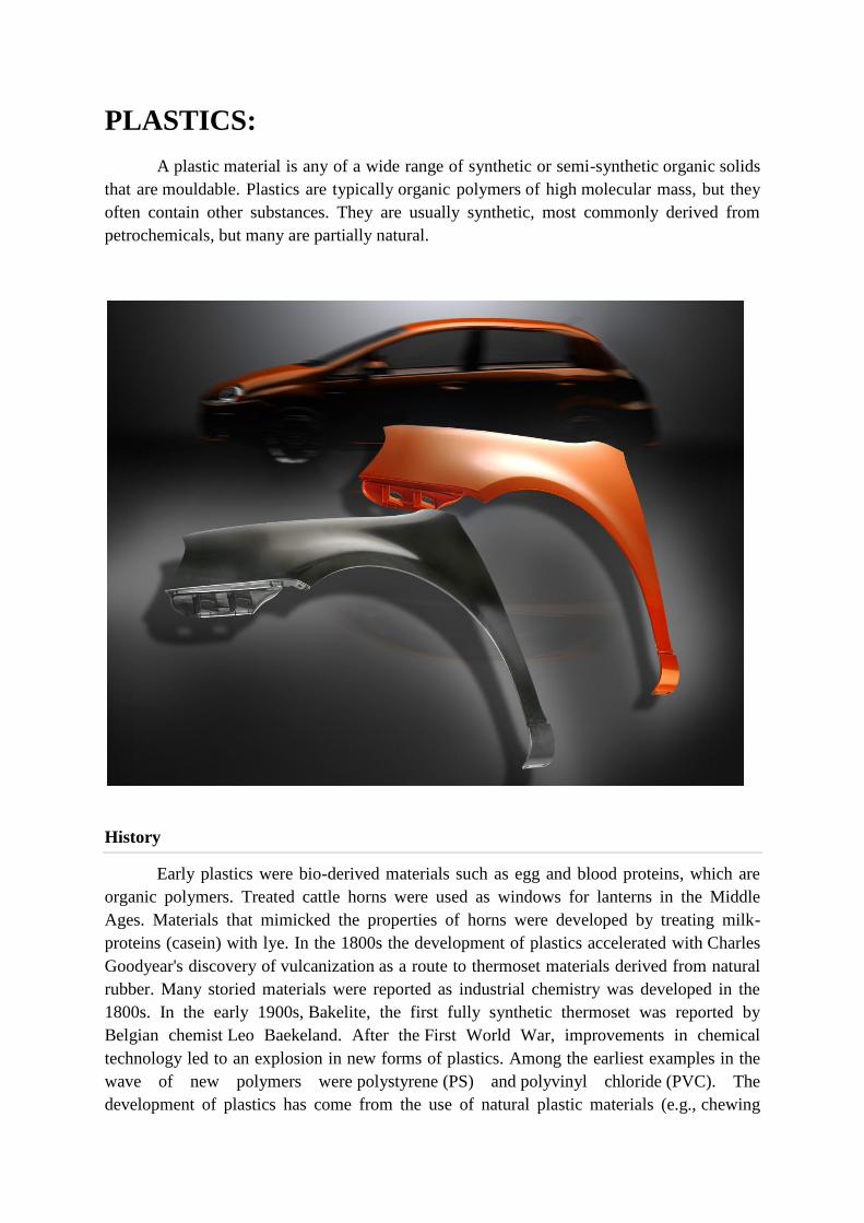
PLASTICS:
A plastic material is any of a wide range of synthetic or semi-synthetic organic solids
that are mouldable. Plastics are typically organic polymers of high molecular mass, but they
often contain other substances. They are usually synthetic, most commonly derived from
petrochemicals, but many are partially natural.
History
Early plastics were bio-derived materials such as egg and blood proteins, which are
organic polymers. Treated cattle horns were used as windows for lanterns in the Middle
Ages. Materials that mimicked the properties of horns were developed by treating milk-
proteins (casein) with lye. In the 1800s the development of plastics accelerated with Charles
Goodyear's discovery of vulcanization as a route to thermoset materials derived from natural
rubber. Many storied materials were reported as industrial chemistry was developed in the
1800s. In the early 1900s, Bakelite, the first fully synthetic thermoset was reported by
Belgian chemist Leo Baekeland. After the First World War, improvements in chemical
technology led to an explosion in new forms of plastics. Among the earliest examples in the
wave of new polymers were polystyrene (PS) and polyvinyl chloride (PVC). The
development of plastics has come from the use of natural plastic materials (e.g., chewing

gum, shellac) to the use of chemically modified natural materials (e.g., rubber,
nitrocellulose, collagen, galalite) and finally to completely synthetic molecules
(e.g., bakelite, epoxy, polyvinyl chloride).
Bakelite
The first so called plastic based on a synthetic polymer was made
from phenol and formaldehyde, with the first viable and cheap synthesis methods invented in
1907, by Leo Hendrik Baekeland, a Belgian-born American living in New York state.
Baekeland was looking for an insulating shellac to coat wires in electric motors and
generators. He found that combining phenol (C6H5OH) and formaldehyde (HCOH) formed a
sticky mass and later found that the material could be mixed with wood flour, asbestos, or
slate dust to create strong and fire resistant "composite" materials. The new material tended
to foam during synthesis, requiring that Baekeland build pressure vessels to force out the
bubbles and provide a smooth, uniform product, as he announced in 1909, in a meeting of the
American Chemical Society.[12]
Bakelite was originally used for electrical and mechanical
parts, coming into widespread use in consumer goods and jewelry in the 1920s. Bakelite was
a purely synthetic material, not derived from living matter. It was also an early thermosetting
plastic.
ASTM: American Standard Test Methods; is a scientific organisation defining standards on
physical and mechanical testing of materials to obtain objective characteristics used for
comparison purposes and for design of articles. The standards are partly used to formulate
ISO (International Standards Organisation) ones.
Composition
Most plastics contain organic polymers. The vast majority of these polymers are
based on chains of carbon atoms alone or with oxygen, sulphur, or nitrogen as well. The
backbone is that part of the chain on the main "path" linking a large number of repeat units
together. To customize the properties of a plastic, different molecular groups "hang" from the
backbone (usually they are "hung" as part of the monomers before linking monomers
together to form the polymer chain). The structure of these "side chains" influence the
properties of the polymer. This fine tuning of the properties of the polymer by repeating unit's
molecular structure has allowed plastics to become an indispensable part of the twenty-first
century world.
Additives
Additives: these are in general low molecular weight chemicals added to plastics and
rubbers to improve certain characteristics such as ultraviolet absorbers, antioxidants and heat
stabilisers, lubricants, plasticisers, flame retardants, cross-linking and blowing agents,
pigments and dyes. Impact modifiers are polymeric materials added to improve the impact
resistance of e.g. PVC, PP, PBT, PA. A separate class of additives are the fillers such as
talcum, wood flour, and reinforcing agents like glass and carbon fibres.
Alloys: strictly speaking, alloys refer to metals and do not exist in plastics. The term is used
interchangeably with blends for mixtures of two or more polymers. Examples are alloys or
blends of polycarbonate (PC) with ABS or with polybutylene terephthalate (PBT).
Blend" an intimate mixture of two or more polymers to obtain the good properties of each,
for example semi-crystalline polypropylene (PP) mixed with 10 to 30% rubbery EPDM
results in a blend with good heat resistance and extraordinary impact resistance. Also the mix
of polycarbonate (PC) with ABS terpolymer results in a blend with the good heat resistance
of the PC part and the low temperature impact resistance of the ABS. Instead of the term
blend, trade literature and producers also use alloy. Blends are made passing the components
in powder or pellet form in a dry blender followed by a heated twin screw extruder to obtain
an intimate blend.
Polymerization process Plastics are one group of polymers that are built from relatively simple units called
monomers (or mers) through a chemical polymerization process. This process is illustrated
below. Processing polymers into end products mainly involves physical phase change such as
melting and solidification (for Thermoplastics) or a chemical reaction (for Thermosets).
Structure of polymers The basic structure of a polymer molecule can be visualized as
a long chain of repeating units, with additional chemical groups forming pendant branches
along the primary "backbone" of the molecule. Although the term plastics has been used
loosely as a synonym for polymer and resin, plastics generally represent polymeric
compounds that are formulated with plasticizers, stabilizers, fillers, and other additives for
purposes of processability and performance. Other polymeric systems include rubbers, fibers,
adhesives, and surface coatings. A variety of processes have been employed to produce the
final plastic parts,

Polymer family, the formation of plastics, and the polymerization process
Classification
Plastics are usually classified by their chemical structure of the polymer's backbone
and side chains. Some important groups in these classifications are
the acrylics, polyesters, silicones, polyurethanes, and halogenated plastics. Plastics can also
be classified by the chemical process used in their synthesis, such as condensation, poly-
addition, and cross-linking.
There are two types of plastics: thermoplastics and thermosetting polymers.
Thermoplastics are the plastics that do not undergo chemical change in their composition
when heated and can be molded again and again.
Thermoplastics
A Thermoplastic, also known as a thermosoftening plastic, is a polymer that
becomes pliable or moldable above a specific temperature, and returns to a solid state upon
cooling. Most thermoplastics have a high molecular weight, whose chains associate
through intermolecular forces; this property allows thermoplastics to be remolded because the
intermolecular interactions spontaneously reform upon cooling. In this way, thermoplastics
differ from thermosetting polymers, which form irreversible chemical bonds during the
curing process; thermoset bonds break down upon melting and do not reform upon cooling.
Thermoplastic materials can be formed into desired shapes under heat and pressure and
become solids on cooling.
• If they are subjected to the same conditions of heat and pressure, they can be reprocessed
into new shapes.
Thermoplastics based on their crystallization are classified into
Amorphous Thermoplastics
• Some thermoplastics donot crystallise on heating and are termed as amorphous plastics
Used in applications where clarity is important.
• They are frequently used in applications where Clarity is important and are subjected
to stress cracking and less chemically resistant.
• Ex: PMMA, PS and PC.
Semi crystalline Thermoplastics.
Thermoplastics which crystallises to some extent are known as Semi crystalline
Thermoplastics..
• They are resistent to Solvents and other Chemicals.
• Ex:PE,PBT, PP and PET.
Examples include polyethylene, polypropylene, polystyrene, polyvinyl-chloride,
and polytetrafluoroethylene (PTFE). Common thermoplastics range from 20,000 to
500,000 amu, while thermosets are assumed to have infinite molecular weight. These chains
are made up of many repeating molecular units, known as repeat units, derived
from monomers; each polymer chain will have several thousand repeating units.
THERMOSETTING PLASTIC
A thermosetting plastic, also known as a thermoset, is polymer material that
irreversibly cures. The cure may be done through heat (generally above 200 °C (392 °F)),
through a chemical reaction (two-partepoxy, for example), or irradiation such as electron
beam processing.
Thermoset materials are usually liquid or malleable prior to curing and designed to
be molded into their final form, or used as adhesives. Others are solids like that of the
molding compound used insemiconductors and integrated circuits (IC). Once hardened a
thermoset resin cannot be reheated and melted back to a liquid form.
According to IUPAC recommendation: A thermosetting polymer is a prepolymer in a
soft solid or viscous state that changes irreversibly into an infusible, insoluble polymer
network by curing. Curing can be induced by the action of heat or suitable radiation, or both.
A cured thermosetting polymer is called a thermoset.
Thermosets can melt and take shape once; after they have solidified, they stay solid.
In the thermosetting process, a chemical reaction occurs that is irreversible. The vulcanization
of rubber is a thermosetting process. Before heating with sulphur, the polyisoprene is a tacky,
slightly runny material, but after vulcanization the product is rigid and non-tacky.

TABLE 1. Effects of additives, fillers, and reinforcements on polymer properties
Additive / Filler / Reinforcement
Common materials Effects on polymer properties
Reinforcing fibers Baron, carbon, fibrous
minerals,
glass, Kevlar
Increases tensile
strength.
Increases flexural
modulus.
Increases heat-
deflection
temperature (HDT).
Resists shrinkage and
warpage.
Conductive fillers Aluminum powders,
carbon
fiber, graphite
Improves electrical
and
thermal conductivity.
Coupling agents Silanes, titanates Improves interface
bonding between polymer
matrix and the
fibers.
Flame retardants Chlorine, bromine,
phosphorous,
metallic salts
Reduces the
occurrence and
spread of combustion.
Extender fillers Calcium carbonate,
silica, clay
Reduces material
cost.
Plasticizers Monomeric liquids,
lowmolecular-
weight materials
Improves melt flow
properties.
Enhances flexibility.
Colorants (pigments and
dyes)
Metal oxides,
chromates, carbon
blacks
Provides
colorfastness.
Protects from
thermal and UV
degradation (with carbon
blacks).
Blowing agents Gas, azo compounds,
hydrazine
derivatives
Generates a cellular
form to obtain a low-
density material.
Other classifications
Other classifications are based on qualities that are relevant for manufacturing
or product design. Examples of such classes are the thermoplastic and
thermoset, elastomer, structural, biodegradable, and electrically conductive. Plastics can also
be classified by various physical properties, such as density, tensile strength, glass transition
temperature, and resistance to various chemical products.
Biodegradable plastic
Biodegradable plastics break down (degrade) upon exposure to sunlight (e.g., ultra-
violet radiation), water or dampness, bacteria, enzymes, wind abrasion, and in some
instances, rodent, pest, or insect attack are also included as forms
of biodegradation or environmental degradation. Some modes of degradation require that the
plastic be exposed at the surface, whereas other modes will only be effective if certain
conditions exist in landfill or composting systems. Starch powder has been mixed with plastic
as a filler to allow it to degrade more easily, but it still does not lead to complete breakdown
of the plastic. Some researchers have actually genetically engineered bacteria that synthesize
a completely biodegradable plastic, but this material, such as Biopol, is expensive at present.
The German chemical company BASF makes Ecoflex, a fully biodegradable polyester for
food packaging applications.
Natural vs synthetic
Main article: Bioplastic
Most plastics are produced from petrochemicals. Motivated by the finiteness of
petrochemical reserves and possibility of global warming, bioplastics are being developed.
Bioplastics are made substantially from renewable plant materials such as cellulose and
starch.
In comparison to the global consumption of all flexible packaging, estimated at 12.3
million tonnes/year, estimates put global production capacity at 327,000 tonnes/year for
related bio-derived materials.
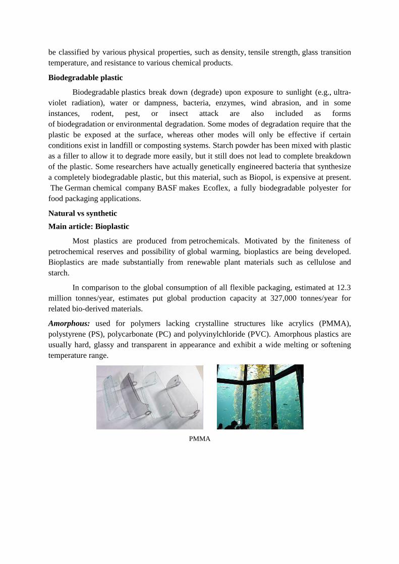
Amorphous: used for polymers lacking crystalline structures like acrylics (PMMA),
polystyrene (PS), polycarbonate (PC) and polyvinylchloride (PVC). Amorphous plastics are
usually hard, glassy and transparent in appearance and exhibit a wide melting or softening
temperature range.
PMMA

PS
PC
Crystalline: Many plastics are semi-crystalline, which means that some 30 to 70% of
crystallites are present in the structure surrounded by an amorphous polymer. These polymers
are non transparent because they exist in two distinct phases. Examples are polypropylene
(PP), polyacetal (POM), polyamides (PA), polybutylene terephtalate (PBT) and they exhibit a
rather sharp softening or melting temperature.
PE
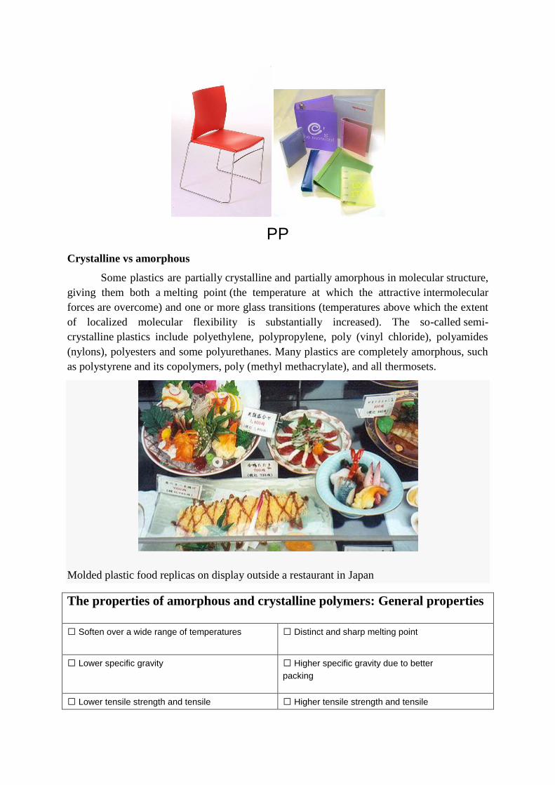
PP
Crystalline vs amorphous
Some plastics are partially crystalline and partially amorphous in molecular structure,
giving them both a melting point (the temperature at which the attractive intermolecular
forces are overcome) and one or more glass transitions (temperatures above which the extent
of localized molecular flexibility is substantially increased). The so-called semi-
crystalline plastics include polyethylene, polypropylene, poly (vinyl chloride), polyamides
(nylons), polyesters and some polyurethanes. Many plastics are completely amorphous, such
as polystyrene and its copolymers, poly (methyl methacrylate), and all thermosets.
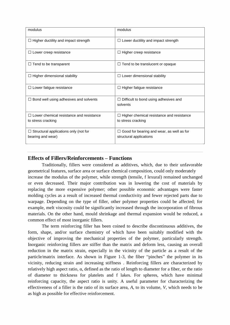
Molded plastic food replicas on display outside a restaurant in Japan
The properties of amorphous and crystalline polymers: General properties
Soften over a wide range of temperatures
Distinct and sharp melting point
Lower specific gravity
Higher specific gravity due to better
packing
Lower tensile strength and tensile Higher tensile strength and tensile
modulus
modulus
Higher ductility and impact strength
Lower ductility and impact strength
Lower creep resistance
Higher creep resistance
Tend to be transparent
Tend to be translucent or opaque
Higher dimensional stability
Lower dimensional stability
Lower fatigue resistance
Higher fatigue resistance
Bond well using adhesives and solvents
Difficult to bond using adhesives and
solvents
Lower chemical resistance and resistance
to stress cracking
Higher chemical resistance and resistance
to stress cracking
Structural applications only (not for
bearing and wear)
Good for bearing and wear, as well as for
structural applications
Effects of Fillers/Reinforcements – Functions
Traditionally, fillers were considered as additives, which, due to their unfavorable
geometrical features, surface area or surface chemical composition, could only moderately
increase the modulus of the polymer, while strength (tensile, f lexural) remained unchanged
or even decreased. Their major contribution was in lowering the cost of materials by
replacing the more expensive polymer; other possible economic advantages were faster
molding cycles as a result of increased thermal conductivity and fewer rejected parts due to
warpage. Depending on the type of filler, other polymer properties could be affected; for
example, melt viscosity could be significantly increased through the incorporation of fibrous
materials. On the other hand, mould shrinkage and thermal expansion would be reduced, a
common effect of most inorganic fillers.
The term reinforcing filler has been coined to describe discontinuous additives, the
form, shape, and/or surface chemistry of which have been suitably modified with the
objective of improving the mechanical properties of the polymer, particularly strength.
Inorganic reinforcing fillers are stiffer than the matrix and deform less, causing an overall
reduction in the matrix strain, especially in the vicinity of the particle as a result of the
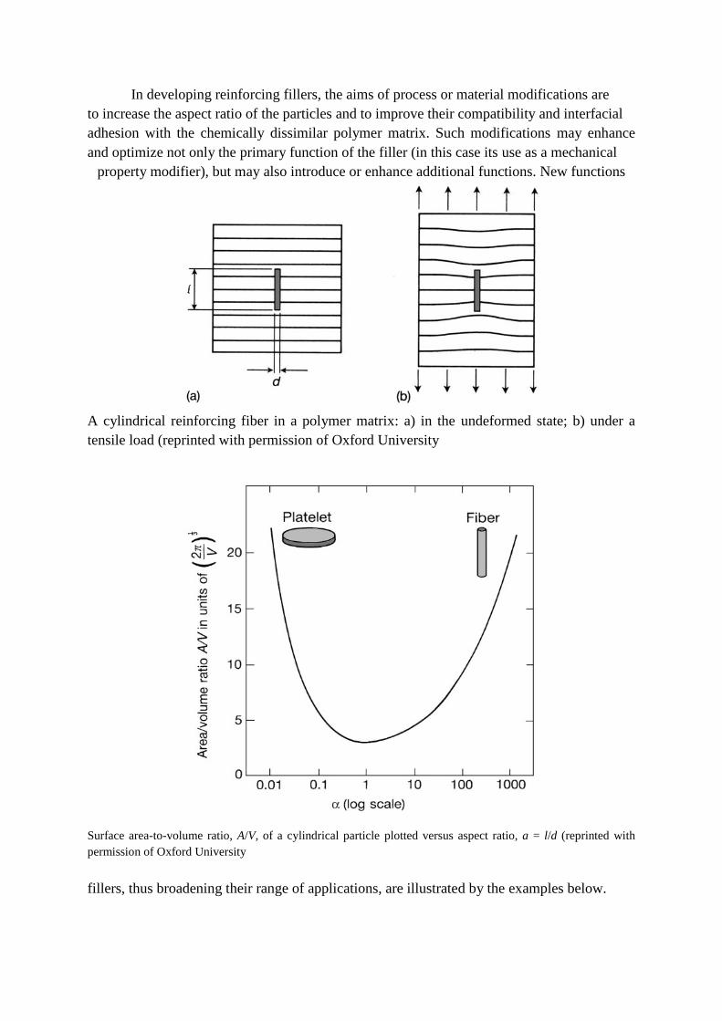
particle/matrix interface. As shown in Figure 1-3, the fiber ―pinches‖ the polymer in its
vicinity, reducing strain and increasing stiffness . Reinforcing fillers are characterized by
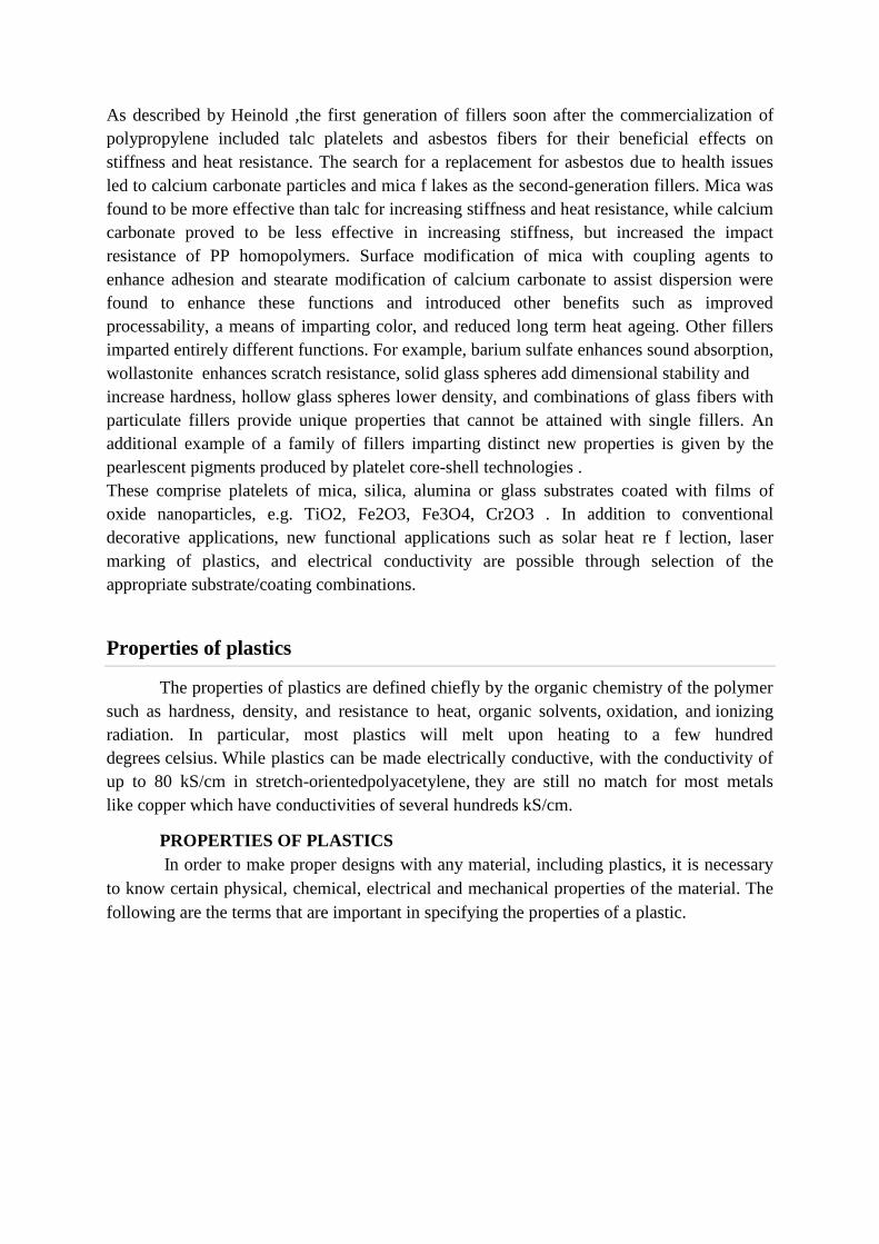
relatively high aspect ratio, α, defined as the ratio of length to diameter for a fiber, or the ratio
of diameter to thickness for platelets and f lakes. For spheres, which have minimal
reinforcing capacity, the aspect ratio is unity. A useful parameter for characterizing the
effectiveness of a filler is the ratio of its surface area, A, to its volume, V, which needs to be
as high as possible for effective reinforcement.
In developing reinforcing fillers, the aims of process or material modifications are
to increase the aspect ratio of the particles and to improve their compatibility and interfacial
adhesion with the chemically dissimilar polymer matrix. Such modifications may enhance
and optimize not only the primary function of the filler (in this case its use as a mechanical
property modifier), but may also introduce or enhance additional functions. New functions
A cylindrical reinforcing fiber in a polymer matrix: a) in the undeformed state; b) under a
tensile load (reprinted with permission of Oxford University
Surface area-to-volume ratio, A/V, of a cylindrical particle plotted versus aspect ratio, a = l/d (reprinted with
permission of Oxford University
fillers, thus broadening their range of applications, are illustrated by the examples below.
As described by Heinold ,the first generation of fillers soon after the commercialization of
polypropylene included talc platelets and asbestos fibers for their beneficial effects on
stiffness and heat resistance. The search for a replacement for asbestos due to health issues
led to calcium carbonate particles and mica f lakes as the second-generation fillers. Mica was
found to be more effective than talc for increasing stiffness and heat resistance, while calcium
carbonate proved to be less effective in increasing stiffness, but increased the impact
resistance of PP homopolymers. Surface modification of mica with coupling agents to
enhance adhesion and stearate modification of calcium carbonate to assist dispersion were
found to enhance these functions and introduced other benefits such as improved
processability, a means of imparting color, and reduced long term heat ageing. Other fillers
imparted entirely different functions. For example, barium sulfate enhances sound absorption,
wollastonite enhances scratch resistance, solid glass spheres add dimensional stability and
increase hardness, hollow glass spheres lower density, and combinations of glass fibers with
particulate fillers provide unique properties that cannot be attained with single fillers. An
additional example of a family of fillers imparting distinct new properties is given by the
pearlescent pigments produced by platelet core-shell technologies .
These comprise platelets of mica, silica, alumina or glass substrates coated with films of
oxide nanoparticles, e.g. TiO2, Fe2O3, Fe3O4, Cr2O3 . In addition to conventional
decorative applications, new functional applications such as solar heat re f lection, laser
marking of plastics, and electrical conductivity are possible through selection of the
appropriate substrate/coating combinations.
Properties of plastics
The properties of plastics are defined chiefly by the organic chemistry of the polymer
such as hardness, density, and resistance to heat, organic solvents, oxidation, and ionizing
radiation. In particular, most plastics will melt upon heating to a few hundred
degrees celsius. While plastics can be made electrically conductive, with the conductivity of
up to 80 kS/cm in stretch-orientedpolyacetylene, they are still no match for most metals
like copper which have conductivities of several hundreds kS/cm.
PROPERTIES OF PLASTICS
In order to make proper designs with any material, including plastics, it is necessary
to know certain physical, chemical, electrical and mechanical properties of the material. The
following are the terms that are important in specifying the properties of a plastic.
Mechanical Properties
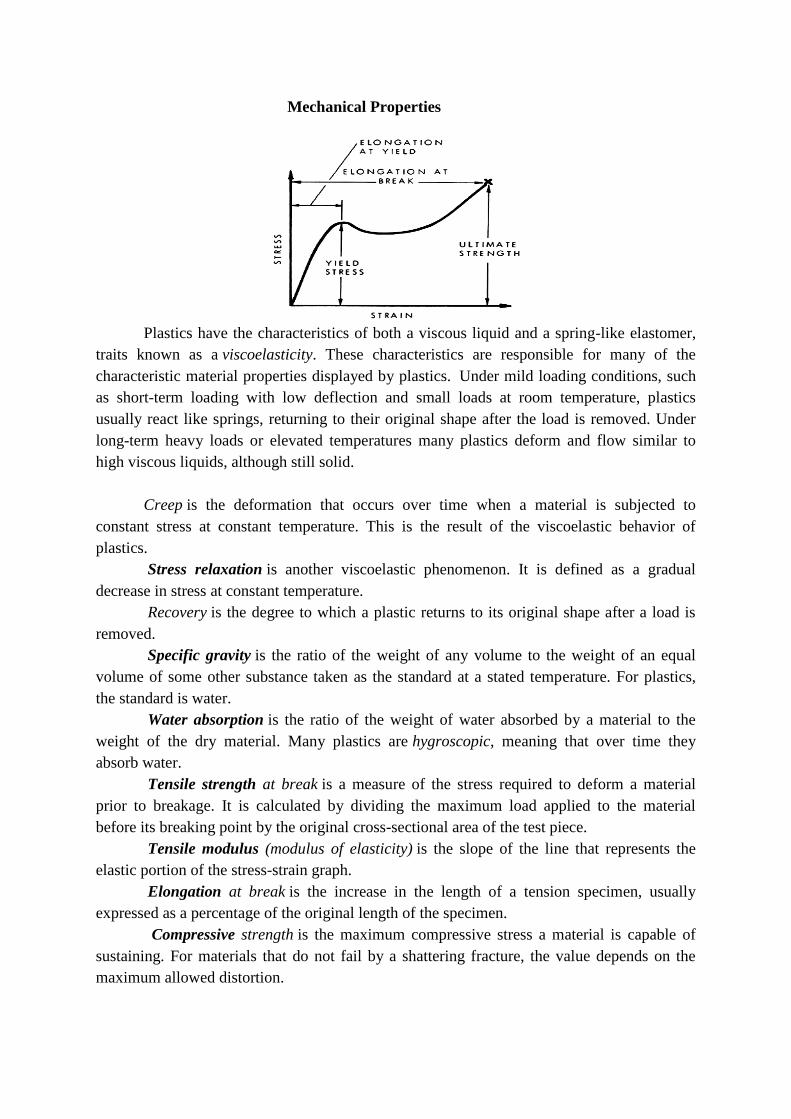
Plastics have the characteristics of both a viscous liquid and a spring-like elastomer,
traits known as a viscoelasticity. These characteristics are responsible for many of the
characteristic material properties displayed by plastics. Under mild loading conditions, such
as short-term loading with low deflection and small loads at room temperature, plastics
usually react like springs, returning to their original shape after the load is removed. Under
long-term heavy loads or elevated temperatures many plastics deform and flow similar to
high viscous liquids, although still solid.
Creep is the deformation that occurs over time when a material is subjected to
constant stress at constant temperature. This is the result of the viscoelastic behavior of
plastics.
Stress relaxation is another viscoelastic phenomenon. It is defined as a gradual
decrease in stress at constant temperature.
Recovery is the degree to which a plastic returns to its original shape after a load is
removed.
Specific gravity is the ratio of the weight of any volume to the weight of an equal
volume of some other substance taken as the standard at a stated temperature. For plastics,
the standard is water.
Water absorption is the ratio of the weight of water absorbed by a material to the
weight of the dry material. Many plastics are hygroscopic, meaning that over time they
absorb water.
Tensile strength at break is a measure of the stress required to deform a material
prior to breakage. It is calculated by dividing the maximum load applied to the material
before its breaking point by the original cross-sectional area of the test piece.
Tensile modulus (modulus of elasticity) is the slope of the line that represents the
elastic portion of the stress-strain graph.
Elongation at break is the increase in the length of a tension specimen, usually
expressed as a percentage of the original length of the specimen.
Compressive strength is the maximum compressive stress a material is capable of
sustaining. For materials that do not fail by a shattering fracture, the value depends on the
maximum allowed distortion.
Flexural strength is the strength of a material in bending expressed as the tensile
stress of the outermost fibers of a bent test sample at the instant of failure.
Flexural modulus is the ratio, within the elastic limit, of stress to the corresponding
strain.
Izod Impact is one of the most common ASTM tests for testing the impact strength
of plastic materials. It gives data to compare the relative ability of materials to resist brittle
fracture as the service temperature decreases.
For finding hardness, Rockwell Number is the net increase in depth of impression as
the load on a penetrator is increased from a fixed minimum load to a high load and then
returned to a minimum load.
Coefficient of thermal expansion is the change in unit length or volume resulting
from a unit change in temperature. Commonly used unit is 10-6
cm/cm/C.
Thermal conductivity is the ability of a material to conduct heat; a physical constant
for the quantity of heat that passes through a unit cube of a material in a unit of time when the
difference in temperature of two faces is 1C.
Heat Deflection temperature (HDT) test is one in which a bar of the polymer is
heated uniformly in a closed chamber while a load of 66psi or 264psi is placed at the center
of the horizontal bar. The HDT is the temperature at which a deflection of 0.25mm is noted at
the center. The HDT indicated how much mass the object must be constructed of to maintain
the desired form. It also provides a measure of the rigidity of the polymer under a load as
well as temperature.
limiting oxygen index is a measure of the minimum oxygen level required to support
combustion of the polymer.
Absorption. Polymers have a potential to absorb various corrodents the come to
contact with, particularly organic liquids. This can result in swelling, cracking and
penetration to the substrate of the component.
Toxicity
Due to their insolubility in water and relative chemical inertness, pure plastics
generally have low toxicity. Some plastic products contain a variety of additives, some of
which can be toxic. For example, plasticizers like adipates and phthalates are often added to
brittle plastics like polyvinyl chloride to make them pliable enough for use in food
packaging, toys, and many other items. Traces of these compounds can leach out of the
product. Owing to concerns over the effects of such leachates, the European Union has
restricted the use of DEHP (di-2-ethylhexyl phthalate) and other phthalates in some
applications. Some compounds leaching from polystyrene food containers have been
proposed to interfere with hormone functions and are suspected human carcinogens.
Whereas the finished plastic may be non-toxic, the monomers used in the manufacture of the
parent polymers may be toxic. In some cases, small amounts of those chemicals can remain
trapped in the product unless suitable processing is employed. For example, the World Health
Organization's International Agency for Research on Cancer (IARC) has recognized
that vinyl chloride, the precursor to PVC, as a human carcinogen.
Environmental issues
Plastics are durable and degrade very slowly; the chemical bonds that make plastic so
durable make it equally resistant to natural processes of degradation. Since the 1950s, one
billion tons of plastic have been discarded and may persist for hundreds or even thousands of
years. Perhaps the biggest environmental threat from plastic comes from nurdles, which are
the raw material from which all plastics are made. They are tiny pre-plastic pellets that kill
large numbers of fish and birds that mistake them for food.
Prior to the ban on the use of CFCs in extrusion of polystyrene (and general use, except in
life-critical fire suppression systems; see Montreal Protocol), the production of polystyrene
contributed to the depletion of the ozone layer; however, non-CFCs are currently used in the
extrusion process.
Incineration of plastics
Plastics can be converted into a fuel since they are usually hydrocarbon-based and can
be broken down into liquid hydrocarbon. One kilogram of waste plastic produces a liter of
hydrocarbon. In some cases, burning plastic can release toxic fumes. Burning the plastic
polyvinyl chloride (PVC) may create dioxin.
Recycling
Thermoplastics can be remelted and reused, and thermoset plastics can be ground up
and used as filler, although the purity of the material tends to degrade with each reuse cycle.
There are methods by which plastics can be broken back down to a feedstock state.
The greatest challenge to the recycling of plastics is the difficulty of automating the
sorting of plastic wastes, making it labor intensive. Typically, workers sort the plastic by
looking at the resin identification code, although common containers like soda bottles can be
sorted from memory. Typically, the caps for PETE bottles are made from a different kind of
plastic which is not recyclable, which presents additional problems to the automated sorting
process. Other recyclable materials such as metals are easier to process mechanically.
However, new processes of mechanical sorting are being developed to increase capacity and
efficiency of plastic recycling.
While containers are usually made from a single type and color of plastic, making
them relatively easy to be sorted, a consumer product like a cellular phone may have many
small parts consisting of over a dozen different types and colors of plastics. In such cases, the
resources it would take to separate the plastics far exceed their value and the item is
discarded. However, developments are taking place in the field of active disassembly, which
may result in more consumer product components being re-used or recycled. Recycling
certain types of plastics can be unprofitable, as well. For example, polystyrene is rarely
recycled because it is usually not cost effective. These unrecycled wastes are typically
disposed of in landfills, incinerated or used to produce electricity at waste-to-energy plants.
A first success in recycling of plastics is Vinyloop, a recycling process and an
approach of the industry to separate PVC from other materials through a process of

dissolution, filtration and separation of contaminations. A solvent is used in a closed loop to
elute PVC from the waste. This makes it possible to recycle composite structure PVC waste
which normally is being incinerated or put in a landfill. Vinyloop-based recycled PVC's
primary energy demand is 46 percent lower than conventional produced PVC. The global
warming potential is 39 percent lower. This is why the use of recycled material leads to a
significant better ecological footprint.
In 1988, to assist recycling of disposable items, the Plastic Bottle Institute of
the Society of the Plastics Industry devised a now-familiar scheme to mark plastic bottles by
plastic type. A plastic container using this scheme is marked with a triangle of three "chasing
arrows", which encloses a number giving the plastic type:
Plastics type marks: the resin identification code[31]
1. PET (PETE), polyethylene terephthalate
2. HDPE, high-density polyethylene
3. PVC, polyvinyl chloride
4. LDPE, low-density polyethylene,
5. PP, polypropylene
6. PS, polystyrene
7. Other types of plastics (see list, below)
Common plastics and uses
Due to their relatively low cost, ease of manufacture, versatility, and imperviousness
to water, plastics are used in an enormous and expanding range of products, from paper clips
to spaceships. They have already displaced many traditional materials, such
as wood, stone, horn and bone, leather, paper, metal, glass, and ceramic, in most of their
former uses.
A chair made with a polypropylene seat
ABS (Acrylonitrile-Butadiene-Styrene)
Typical Applications
Automotive (instrument and interior trim panels, glove compartment doors, wheel covers,
mirror housings, etc.)
Refrigerators, small appliance housings and power tools applications (hair dryers,
blenders, food processors, lawnmowers, etc.)
Telephone housings, typewriter housings, typewriter keys
Recreational vehicles such as golf carts and jet skis.
PA 6 (Polyamide 6, Nylon 6, or
Polycaprolactam)
Applications

Used in many structural applications because of its good mechanical strength and rigidity. It
is
used in bearings because of its good wear resistance.
PA 12 (Polyamide 12 or Nylon 12)
Typical Applications
Gear wheels for water meters and business machines
Cable ties
Cams
Slides
Bearings
PA 66 (Polyamide 66, Nylon 66, or Poly
(hexamethylene adipamide))
Applications
Competes with PA 6 for most applications. PA 66 is heavily used in the following:
The automotive industry
Appliance housings
Where impact resistance and strength are required
PBT (Polybutylene Terephthalates)
Typical Applications
Household appliances (e.g., food processor blades, vacuum cleaner parts, fans, hair dryer
housings, coffee makers)
Electronics (e.g., switches, motor housings, fuse cases, key caps for computer keyboards,
connectors, fiber optic buffer tubing)
Automotive (e.g., grilles, body panels, wheel covers, and components for doors and
windows)
PC (Polycarbonate)
Typical Applications
Electronic and business equipment (e.g., computer parts, connectors)
Appliances (e.g., food processors, refrigerator drawers)
Transportation (e.g., head lights, tail lights, instrument panels)
PC|ABS (Polycarbonate-Acrylonitrile-
Butadiene-Styrene Blend)
Typical Applications
Computer and business machine housings
Electrical applications
Cellular phones
Lawn and garden equipment
Automotive components (instrument panels, interior trim, and wheel covers)
PC|PBT (Polycarbonate |
Polybutyleneterephthalate Blend)
Typical Applications
Gear cases and automotive (bumpers)
Applications that require chemical and corrosion resistance, high heat resistance, high
impact strength over wide temperature ranges, and high dimensional stability
PE-HD (High Density Polyethylene)
Typical Applications
Major use is in blow-molding (packaging) applications such as:
Containers in refrigeration units
Storage vessels
Household goods (kitchenware)
Seal caps
Bases for PET bottles
PEI (Polyetherimide)
Typical Applications
Automotive (engine components: temperature sensors, fuel and air handling devices
Electrical/electronics (connector materials, printed circuit boards, circuit chip carriers,
explosion proof boxes)
Packaging applications
Aircraft (interior materials)
Medical (surgical staplers, tool housings, non-implant devices)
PE-LD (Low Density Polyethylene)
Typical Applications
Closures
Bowls
Bins
Pipe couplings
PET (Polyethylene Terephthalate)
Typical Applications
Automotive (structural components such as mirror backs, and grille supports, electrical
parts such as head lamp reflectors and alternator housings)
Electrical applications (motor housings, electrical connectors, relays, and switches,
microwave oven interiors)
Industrial applications (furniture chair arms, pump housings, hand tools)
PETG (Glycol-modified PET; Copolyesters)
Typical Applications
PETGs offer a desirable combination of properties such as clarity, toughness, and stiffness.
Applications include:
Medical devices (test tubes and bottles)
Toys
Displays
Lighting fixtures
Face shields
Refrigerator crisper pans
PMMA (Polymethyl Methacrylate)
Typical Applications
Automotive (signal light devices, instrument panels)
Medical (blood cuvettes)
Industrial (video discs, lighting diffusers, display shelving)
Consumer (drinking tumblers, stationery accessories)
POM (Polyacetal or Polyoxymethylene)
Applications
Acetals have a low coefficient of friction and good dimensional stability. This makes it ideal
for
use in gears and bearings. Due to its high temperature resistance, it is used in plumbing (valve
and pump housings) and lawn equipment.
PP (Polypropylene)
Typical Applications
Automotive (mostly mineral-filled PP is used: dashboard components, ductwork, fans,
and some under-hood components)
Appliances (doorliners for dishwashers, ductwork for dryers, wash racks and lids for
clothes washers, refrigerator liners)
Consumer products (lawn/garden furniture, components of lawn mowers, sprinklers)
PPE|PPO (Polypropylene Ether Blends)
Typical Applications
Household appliances (dishwasher, washing machine)
Electrical applications, such as control housings, fiber-optic connectors
PS (Polystyrene)
Typical Applications
Packaging
Housewares (tableware, trays)
Electrical (transparent housings, light diffusers, insulating film)
PVC (Polyvinyl Chloride)
Typical Applications
Water distribution piping
Home plumbing
House siding
Business machine housings
Electronics packaging
Medical apparatus
Packaging for foodstuffs
SAN (Styrene Acrylonitrile)
Typical Applications
Electrical (receptacles, mixer bowls, housings, etc. for kitchen appliances, refrigerator
fittings, chassis for television sets, cassette boxes)
Automotive (head lamp bodies, reflectors, glove compartments, instrument panel covers)
Household appliances (tableware, cutlery, beakers)
Cosmetic packs
Polyester (PES) – Fibers, textiles.
High-density polyethylene (HDPE) – Detergent bottles, milk jugs, and molded plastic
cases.
Polyvinylidene chloride (PVDC) (Saran) – Food packaging.
Low-density polyethylene (LDPE) – Outdoor furniture, siding, floor tiles, shower
curtains, clamshell packaging.

High impact polystyrene (HIPS) -: Refrigerator liners, food packaging, vending cups.
Polyurethanes (PU) – Cushioning foams, thermal insulation foams, surface coatings,
printing rollers (Currently 6th or 7th most commonly used plastic material, for instance
the most commonly used plastic in cars).
Special purpose plastics
Melamine formaldehyde (MF) – One of the aminoplasts, and used as a multi-colorable
alternative to phenolics, for instance in moldings (e.g., break-resistance alternatives to
ceramic cups, plates and bowls for children) and the decorated top surface layer of the
paper laminates (e.g., Formica).
Plastarch material – Biodegradable and heat resistant, thermoplastic composed
of modified corn starch.
Phenolics (PF) or (phenol formaldehydes) – High modulus, relatively heat resistant, and
excellent fire resistant polymer. Used for insulating parts in electrical fixtures, paper
laminated products (e.g., Formica), thermally insulation foams. It is a thermosetting
plastic, with the familiar trade name Bakelite, that can be molded by heat and pressure
when mixed with a filler-like wood flour or can be cast in its unfilled liquid form or cast
as foam (e.g., Oasis). Problems include the probability of moldings naturally being dark
colors (red, green, brown), and as thermoset it is difficult to recycle.
Polyetheretherketone (PEEK) – Strong, chemical- and heat-resistant
thermoplastic, biocompatibility allows for use in medical implant applications, aerospace
moldings. One of the most expensive commercial polymers.
Polyetherimide (PEI) (Ultem) – A high temperature, chemically stable polymer that does
not crystallize.
Polylactic acid (PLA) – A biodegradable, thermoplastic found converted into a variety of
aliphatic polyesters derived from lactic acid which in turn can be made by fermentation
of various agricultural products such as corn starch, once made from dairy products.
Polymethyl methacrylate (PMMA) – Contact lenses (of the original "hard" variety),
glazing (best known in this form by its various trade names around the world; e.g.,
Perspex, Oroglas, Plexiglas), aglets, fluorescent light diffusers, rear light covers for
vehicles. It forms the basis of artistic and commercial acrylic paints when suspended in
water with the use of other agents.
Polytetrafluoroethylene (PTFE) – Heat-resistant, low-friction coatings, used in things like
non-stick surfaces for frying pans, plumber's tape and water slides. It is more commonly
known as Teflon.
Urea-formaldehyde (UF) – One of the aminoplasts and used as a multi-colorable
alternative to phenolics. Used as a wood adhesive (for plywood, chipboard, hardboard)
and electrical switch housings.
Etymology
The word plastic is derived from the Greek πλαστικός (plastikos) meaning capable of being
shaped or molded, from πλαστός (plastos) meaning molded. It refers to their malleability,

orplasticity during manufacture, that allows them to be cast, pressed, or extruded into a
variety of shapes—such as films, fibers, plates, tubes, bottles, boxes, and much more.
The common word plastic should not be confused with the technical adjective plastic, which
is applied to any material which undergoes a permanent change of shape (plastic
deformation) when strained beyond a certain point. Aluminum which is stamped or forged,
for instance, exhibits plasticity in this sense, but is not plastic in the common sense; in
contrast, in their finished forms, some plastics will break before deforming and therefore are
not plastic in the technical sense.
Different manufacturing processes for Plastics: • Injection Moulding.
• Compression Moulding.
• Blow Moulding.
• Compression Moulding.
• Plastics Extrusion.
• Thermoforming.
• Slush Moulding.
• Transfer moulding.
• Calendaring.
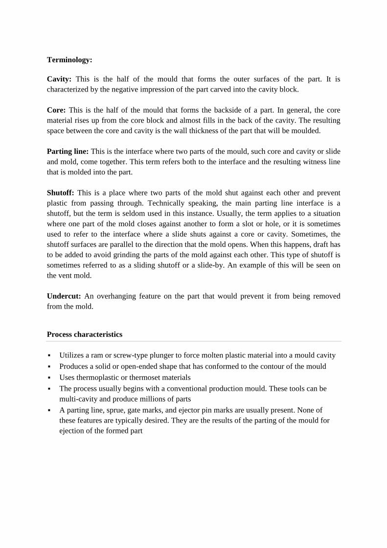
Injection Moulding
Injection moulding is a manufacturing process for producing parts from
both thermoplastic and thermosetting plastic materials. Material is fed into a heated barrel,
mixed, and forced into a mould cavity where it cools and hardens to the configuration of the
cavity. After a product is designed, usually by an industrial designer or an engineer, moulds
are made by a mouldmaker (or toolmaker) from metal, usually either steel or aluminum, and
precision-machined to form the features of the desired part. Injection moulding is widely used
for manufacturing a variety of parts, from the smallest component to entire body
panels of cars.
Injection Moulding: Mould Construction and Part Design : Mold
Mold or die are the common terms used to describe the tooling used to produce
plastic parts in molding. Since molds have been expensive to manufacture, they were usually
only used in mass production where thousands of parts were being produced. Typical molds
are constructed from hardened steel, pre-hardened steel, aluminum, and/or beryllium-
copper alloy. The choice of material to build a mold from is primarily one of economics; in
general, steel molds cost more to construct, but their longer lifespan will offset the higher
initial cost over a higher number of parts made before wearing out. Pre-hardened steel molds
are less wear-resistant and are used for lower volume requirements or larger components. The
typical steel hardness is 38–45 on the Rockwell-C scale. Hardened steel molds are heat
treated after machining. These are by far the superior in terms of wear resistance and lifespan.
Typical hardness ranges between 50 and 60 Rockwell-C (HRC). Aluminum molds can cost
substantially less, and, when designed and machined with modern computerized equipment,
can be economical for molding tens or even hundreds of thousands of parts. Beryllium copper
is used in areas of the mold that require fast heat removal or areas that see the most shear heat
generated. The molds can be manufactured either by CNC machining or by using electrical
discharge machining processes.
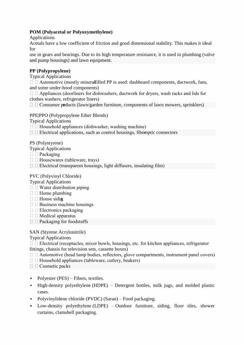
Injection molding die with side pulls
"A" side of die for 25% glass-filled acetal with 2 side pulls.
Close up of removable insert in "A" side.
"B" side of die with side pull actuators.
Insert removed from die.
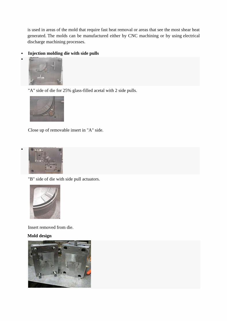
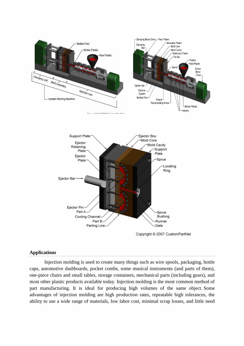
Mold design
Standard two plates tooling – core and cavity are inserts in a mold base – "family mold" of
five different parts:
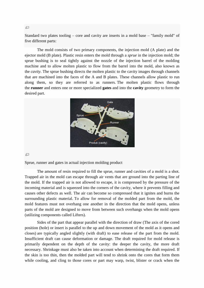
The mold consists of two primary components, the injection mold (A plate) and the
ejector mold (B plate). Plastic resin enters the mold through a sprue in the injection mold; the
sprue bushing is to seal tightly against the nozzle of the injection barrel of the molding
machine and to allow molten plastic to flow from the barrel into the mold, also known as
the cavity. The sprue bushing directs the molten plastic to the cavity images through channels
that are machined into the faces of the A and B plates. These channels allow plastic to run
along them, so they are referred to as runners. The molten plastic flows through
the runner and enters one or more specialized gates and into the cavity geometry to form the
desired part.
Sprue, runner and gates in actual injection molding product
The amount of resin required to fill the sprue, runner and cavities of a mold is a shot.
Trapped air in the mold can escape through air vents that are ground into the parting line of
the mold. If the trapped air is not allowed to escape, it is compressed by the pressure of the
incoming material and is squeezed into the corners of the cavity, where it prevents filling and
causes other defects as well. The air can become so compressed that it ignites and burns the
surrounding plastic material. To allow for removal of the molded part from the mold, the
mold features must not overhang one another in the direction that the mold opens, unless
parts of the mold are designed to move from between such overhangs when the mold opens
(utilizing components called Lifters).
Sides of the part that appear parallel with the direction of draw (The axis of the cored
position (hole) or insert is parallel to the up and down movement of the mold as it opens and
closes) are typically angled slightly (with draft) to ease release of the part from the mold.
Insufficient draft can cause deformation or damage. The draft required for mold release is
primarily dependent on the depth of the cavity: the deeper the cavity, the more draft
necessary. Shrinkage must also be taken into account when determining the draft required. If
the skin is too thin, then the molded part will tend to shrink onto the cores that form them
while cooling, and cling to those cores or part may warp, twist, blister or crack when the
cavity is pulled away. The mold is usually designed so that the molded part reliably remains
on the ejector (B) side of the mold when it opens, and draws the runner and the sprue out of
the (A) side along with the parts. The part then falls freely when ejected from the (B) side.
Tunnel gates, also known as submarine or mold gates, are located below the parting line or
mold surface. An opening is machined into the surface of the mold on the parting line. The
molded part is cut (by the mold) from the runner system on ejection from the mold. Ejector
pins, also known as knockout pins, are circular pins placed in either half of the mold (usually
the ejector half), which push the finished molded product, or runner system out of a mold.
The standard method of cooling is passing a coolant (usually water) through a series of
holes drilled through the mold plates and connected by hoses to form a continuous pathway.
The coolant absorbs heat from the mold (which has absorbed heat from the hot plastic) and
keeps the mold at a proper temperature to solidify the plastic at the most efficient rate.
To ease maintenance and venting, cavities and cores are divided into pieces,
called inserts, and sub-assemblies, also called inserts, blocks, orchase blocks. By substituting
interchangeable inserts, one mold may make several variations of the same part.
More complex parts are formed using more complex molds. These may have sections called
slides, that move into a cavity perpendicular to the draw direction, to form overhanging part
features. When the mold is opened, the slides are pulled away from the plastic part by using
stationary ―angle pins‖ on the stationary mold half. These pins enter a slot in the slides and
cause the slides to move backward when the moving half of the mold opens. The part is then
ejected and the mold closes. The closing action of the mold causes the slides to move forward
along the angle pins.
Some molds allow previously molded parts to be reinserted to allow a new plastic
layer to form around the first part. This is often referred to as overmolding. This system can
allow for production of one-piece tires and wheels.
Two-shot or multi-shot molds are designed to "overmold" within a single molding
cycle and must be processed on specialized injection molding machines with two or more
injection units. This process is actually an injection molding process performed twice. In the
first step, the base color material is molded into a basic shape, which contains spaces for the
second shot. Then the second material, a different color, is injection-molded into those
spaces. Pushbuttons and keys, for instance, made by this process have markings that cannot
wear off, and remain legible with heavy use.
A mold can produce several copies of the same parts in a single "shot". The number of
"impressions" in the mold of that part is often incorrectly referred to as cavitation. A tool
with one impression will often be called a single impression(cavity) mold. A mold with 2 or
more cavities of the same parts will likely be referred to as multiple impression (cavity)
mold. Some extremely high production volume molds (like those for bottle caps) can have
over 128 cavities.
In some cases multiple cavity tooling will mold a series of different parts in the same
tool. Some toolmakers call these molds family molds as all the parts are related. Examples
include plastic model kits.
Terminology:
Cavity: This is the half of the mould that forms the outer surfaces of the part. It is
characterized by the negative impression of the part carved into the cavity block.
Core: This is the half of the mould that forms the backside of a part. In general, the core
material rises up from the core block and almost fills in the back of the cavity. The resulting
space between the core and cavity is the wall thickness of the part that will be moulded.
Parting line: This is the interface where two parts of the mould, such core and cavity or slide
and mold, come together. This term refers both to the interface and the resulting witness line
that is molded into the part.
Shutoff: This is a place where two parts of the mold shut against each other and prevent
plastic from passing through. Technically speaking, the main parting line interface is a
shutoff, but the term is seldom used in this instance. Usually, the term applies to a situation
where one part of the mold closes against another to form a slot or hole, or it is sometimes
used to refer to the interface where a slide shuts against a core or cavity. Sometimes, the
shutoff surfaces are parallel to the direction that the mold opens. When this happens, draft has
to be added to avoid grinding the parts of the mold against each other. This type of shutoff is
sometimes referred to as a sliding shutoff or a slide-by. An example of this will be seen on
the vent mold.
Undercut: An overhanging feature on the part that would prevent it from being removed
from the mold.
Process characteristics
Utilizes a ram or screw-type plunger to force molten plastic material into a mould cavity
Produces a solid or open-ended shape that has conformed to the contour of the mould
Uses thermoplastic or thermoset materials
The process usually begins with a conventional production mould. These tools can be
multi-cavity and produce millions of parts
A parting line, sprue, gate marks, and ejector pin marks are usually present. None of
these features are typically desired. They are the results of the parting of the mould for
ejection of the formed part
Applications
Injection molding is used to create many things such as wire spools, packaging, bottle
caps, automotive dashboards, pocket combs, some musical instruments (and parts of them),
one-piece chairs and small tables, storage containers, mechanical parts (including gears), and
most other plastic products available today. Injection molding is the most common method of
part manufacturing. It is ideal for producing high volumes of the same object. Some
advantages of injection molding are high production rates, repeatable high tolerances, the
ability to use a wide range of materials, low labor cost, minimal scrap losses, and little need
to finish parts after molding. Some disadvantages of this process are expensive equipment
investment, potentially high running costs, and the need to design moldable parts.
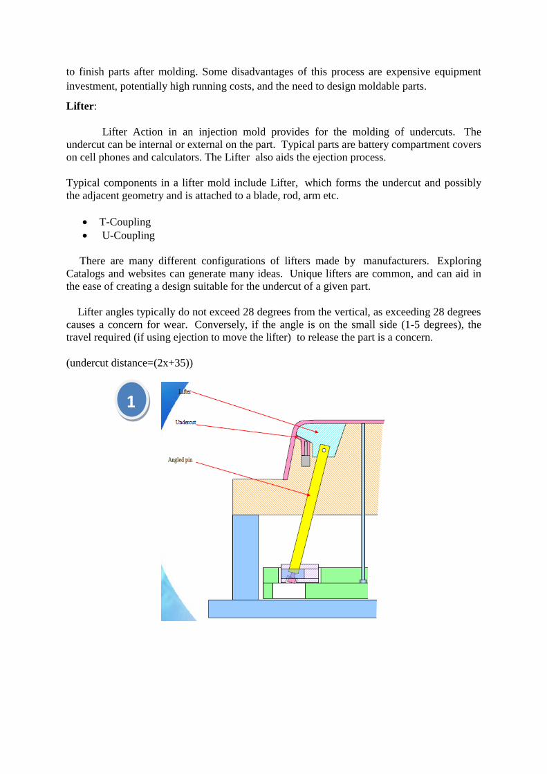
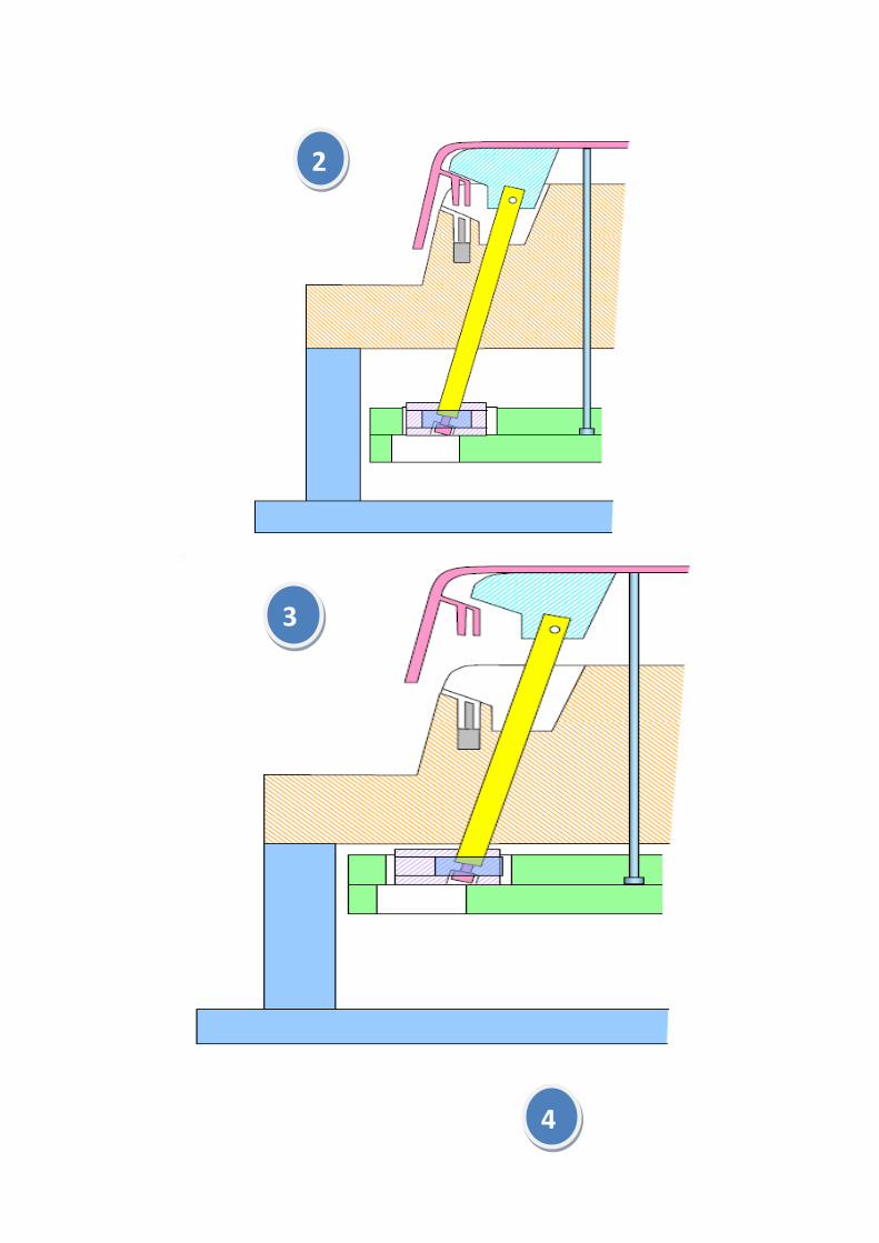
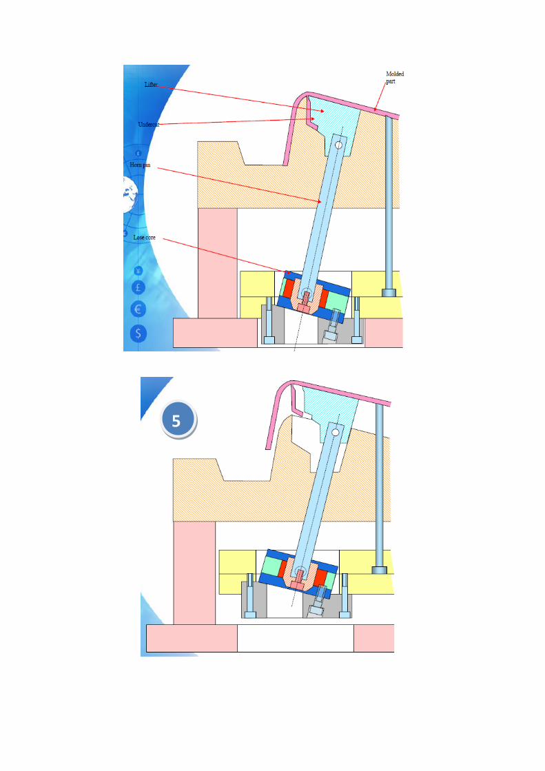
Lifter:
Lifter Action in an injection mold provides for the molding of undercuts. The
undercut can be internal or external on the part. Typical parts are battery compartment covers
on cell phones and calculators. The Lifter also aids the ejection process.
Typical components in a lifter mold include Lifter, which forms the undercut and possibly
the adjacent geometry and is attached to a blade, rod, arm etc.
T-Coupling
U-Coupling
There are many different configurations of lifters made by manufacturers. Exploring
Catalogs and websites can generate many ideas. Unique lifters are common, and can aid in
the ease of creating a design suitable for the undercut of a given part.
Lifter angles typically do not exceed 28 degrees from the vertical, as exceeding 28 degrees
causes a concern for wear. Conversely, if the angle is on the small side (1-5 degrees), the
travel required (if using ejection to move the lifter) to release the part is a concern.
(undercut distance=(2x+35))
1
4
3
2
5

6
7
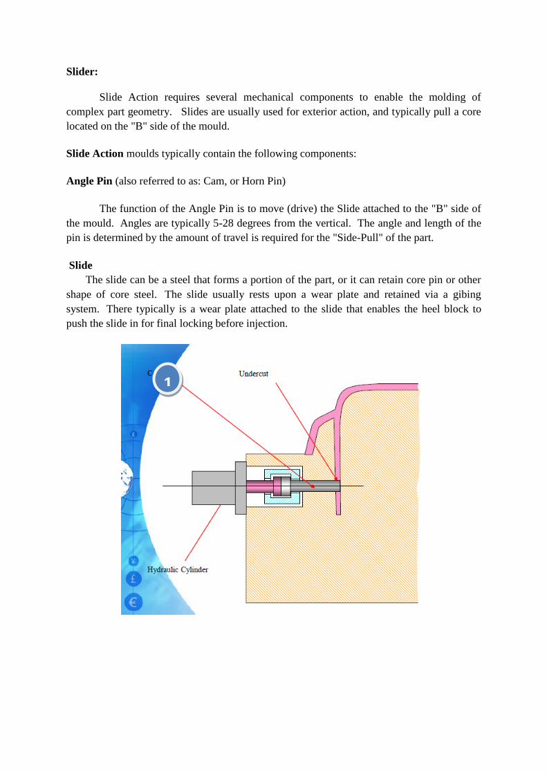
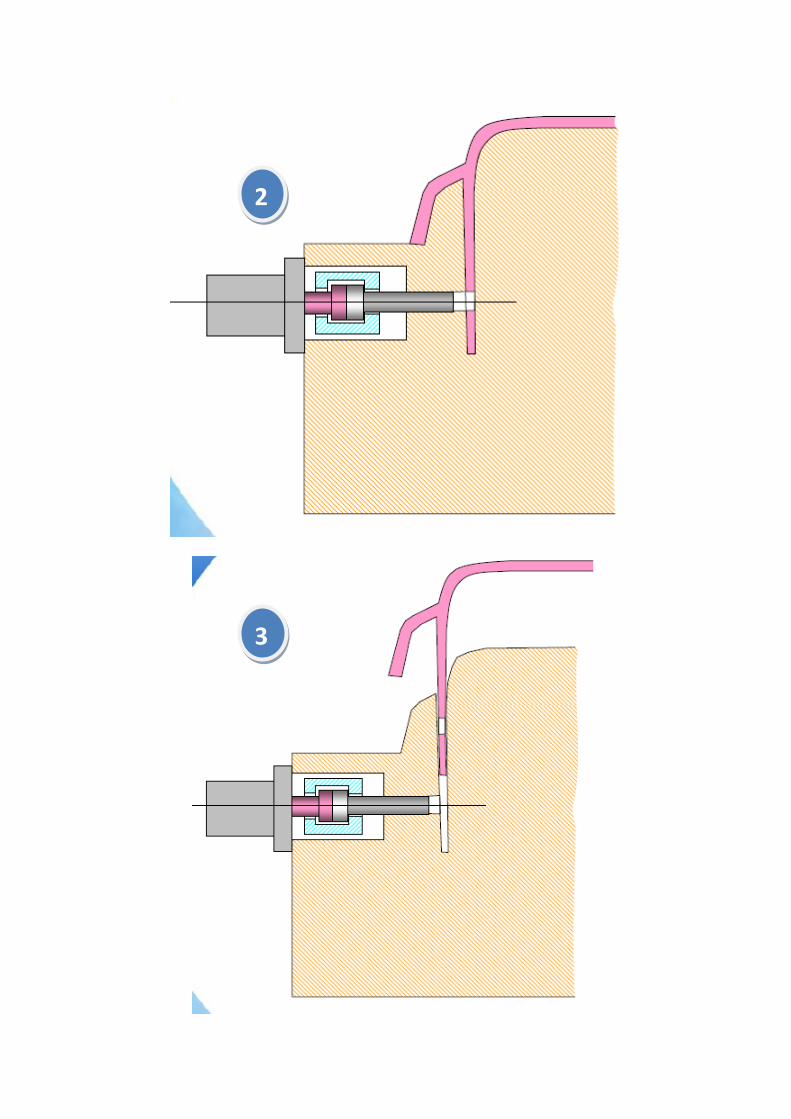
Slider:
Slide Action requires several mechanical components to enable the molding of
complex part geometry. Slides are usually used for exterior action, and typically pull a core
located on the "B" side of the mould.
Slide Action moulds typically contain the following components:
Angle Pin (also referred to as: Cam, or Horn Pin)
The function of the Angle Pin is to move (drive) the Slide attached to the "B" side of
the mould. Angles are typically 5-28 degrees from the vertical. The angle and length of the
pin is determined by the amount of travel is required for the "Side-Pull" of the part.
Slide
The slide can be a steel that forms a portion of the part, or it can retain core pin or other
shape of core steel. The slide usually rests upon a wear plate and retained via a gibing
system. There typically is a wear plate attached to the slide that enables the heel block to
push the slide in for final locking before injection.
1
2
3
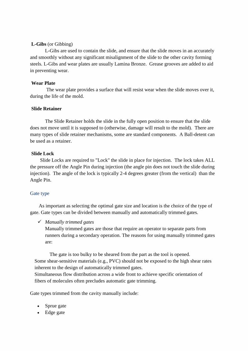
L-Gibs (or Gibbing)
L-Gibs are used to contain the slide, and ensure that the slide moves in an accurately
and smoothly without any significant misalignment of the slide to the other cavity forming
steels. L-Gibs and wear plates are usually Lamina Bronze. Grease grooves are added to aid
in preventing wear.
Wear Plate
The wear plate provides a surface that will resist wear when the slide moves over it,
during the life of the mold.
Slide Retainer
The Slide Retainer holds the slide in the fully open position to ensure that the slide
does not move until it is supposed to (otherwise, damage will result to the mold). There are
many types of slide retainer mechanisms, some are standard components. A Ball-detent can
be used as a retainer.
Slide Lock
Slide Locks are required to "Lock" the slide in place for injection. The lock takes ALL
the pressure off the Angle Pin during injection (the angle pin does not touch the slide during
injection). The angle of the lock is typically 2-4 degrees greater (from the vertical) than the
Angle Pin.
Gate type
As important as selecting the optimal gate size and location is the choice of the type of
gate. Gate types can be divided between manually and automatically trimmed gates.
Manually trimmed gates
Manually trimmed gates are those that require an operator to separate parts from
runners during a secondary operation. The reasons for using manually trimmed gates
are:
The gate is too bulky to be sheared from the part as the tool is opened.
Some shear-sensitive materials (e.g., PVC) should not be exposed to the high shear rates
inherent to the design of automatically trimmed gates.
Simultaneous flow distribution across a wide front to achieve specific orientation of
fibers of molecules often precludes automatic gate trimming.
Gate types trimmed from the cavity manually include:
Sprue gate
Edge gate
Tab gate
Overlap gate
Fan gate
Film gate
Diaphragm gate
External ring
Spoke or multipoint gate
Automatically trimmed gates
Automatically trimmed gates incorporate features in the tool to break or shear the
gate as the molding tool is opened to eject the part. Automatically trimmed gates
should be used to:
Avoid gate removal as a secondary operation.
Maintain consistent cycle times for all shots.
Minimize gate scars.
Gate types trimmed from the cavity automatically include:
Pin gate
Submarine (tunnel) gates
Hot runner gates
Valve gates
Sprue gate
Recommended for single cavity molds or for parts requiring symmetrical filling.
This type of gate is suitable for thick sections because holding pressure is more effective. A
short sprue is favored, enabling rapid mold filling and low-pressure losses. A cold slug well
should be included opposite the gate. The disadvantage of using this type of gate is the gate
mark left on the part surface after the runner (or sprue) is trimmed off. Freeze-off is
controlled by the part thickness rather than determined the gate thickness. Typically, the part
shrinkage near the sprue gate will be low; shrinkage in the sprue gate will be high. This
results in high tensile stresses near the gate.
Dimensions
The starting sprue diameter is controlled by the machine nozzle. The sprue
diameter here must be about 0.5 mm larger than the nozzle exit diameter. Standard sprue
bushings have a taper of 2.4 degrees, opening toward the part. Therefore, the sprue length
will control the diameter of the gate where it meets the part; the diameter should be at least
1.5 mm larger than or approximately twice the thickness of the part at that point. The junction
of sprue and part should be radiused to prevent stress cracking
A smaller taper angle (a minimum of one degree) risks not releasing the sprue from
the sprue bushing on ejection. A larger taper wastes material and extends cooling time.

Non-standard sprue tapers will be more expensive, with little gain.
Sprue gate
Edge gate
The edge or side gate is suitable for medium and thick sections and can be used on
multicavity two plate tools. The gate is located on the parting line and the part fills from the
side, top or bottom.
Dimensions
The typical gate size is 80% to 100% of the part thickness up to 3.5 mm and 1.0 to 12 mm
wide. The gate land should be no more than 1.0 mm in length, with 0.5 mm being the
optimum.
Edge gate
Tab gate
A tab gate is typically employed for flat and thin parts, to reduce the shear stress in the
cavity. The high shear stress generated around the gate is confined to the auxiliary tab, which
is trimmed off after molding. A tab gate is often used for molding P.
Dimensions
The minimum tab width is 6 mm. The minimum tab thickness is 75% of the depth of the
cavity.
Tab gate
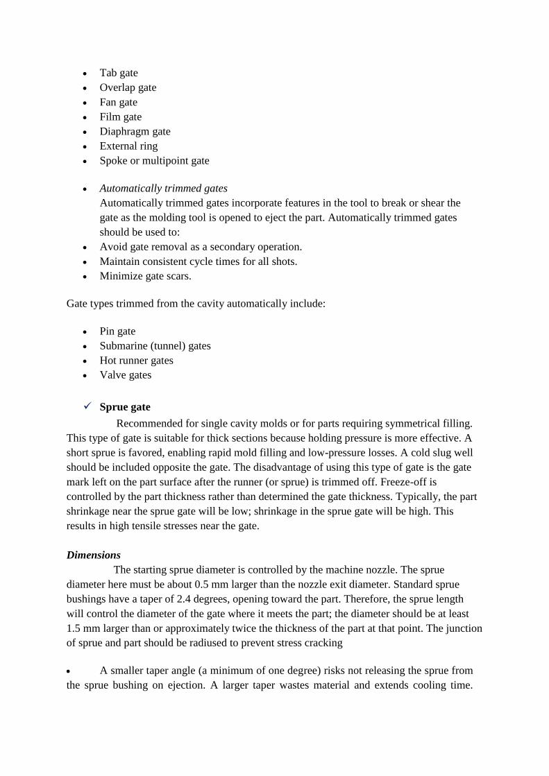
Overlap gate
An overlap gate is similar to an edge gate, except the gate overlaps the wall or surfaces. This
type of gate is typically used to eliminate jetting.
Dimensions
The typical gate size is 10% to 80% of the part thickness and 1.0 to 12 mm wide. The gate
land should be no more than 1.0 mm in length, with 0.5 mm being the optimum.
Overlap gate
Fan gate
A fan gate is a wide edge gate with variable thickness. This type is often used for thick-
sectioned moldings and enables slow injection without freeze-off, which is favored for low
stress moldings or where warpage and dimensional stability are main concerns. The gate
should taper in both width and thickness, to maintain a constant cross sectional area. This will
ensure that:
The melt velocity will be constant.
The entire width is being used for the flow.
The pressure is the same across the entire width.
Dimensions
As with other manually trimmed gates, the maximum thickness should be no more than 80%
of the part thickness. The gate width varies typically from 6 mm up to 25% of the cavity
length.
Film or flash gate
A film or flash gate consists of a straight runner and a gate land across either the entire length
or a portion of the cavity. It is used for long flat thin walled parts and provides even filling.

Shrinkage will be more uniform which is important especially for fiber reinforced
thermoplastics and where warpage must be kept to a minimum.
Dimensions
The gate size is small, typically 0.25mm to 0.5mm thick. The land area (gate length) must
also be kept small, approximately 0.5 to 1.0 mm long.
Film or flash gate.
Diaphragm gate
A diaphragm gate is often used for gating cylindrical or round parts that have an open inside
diameter. It is used for single cavity molds that have a small to medium internal diameter. It
is used when concentricity is important and the presence of a weld line is not acceptable.
Dimensions
Typical gate thickness is 0.25 to 1.5 mm.
Internal ring gate.
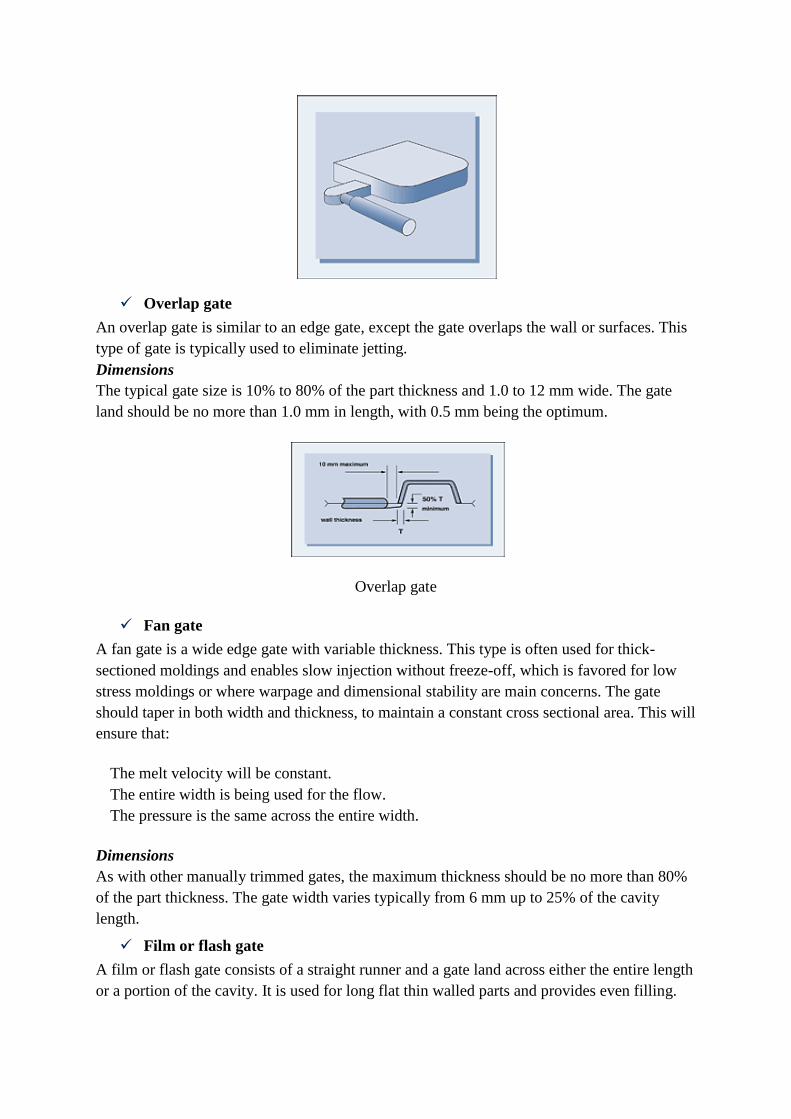
External ring gate
This gate is used for cylindrical or round parts in a multicavity mould or when a diaphragm
gate is not practical. Material enters the external ring from one side forming a weld line on
the opposite side of the runner this weld line is not typically transferred to the part.
Dimensions
Typical gate thickness is 0.25 to 1.5 mm.
External ring gate.
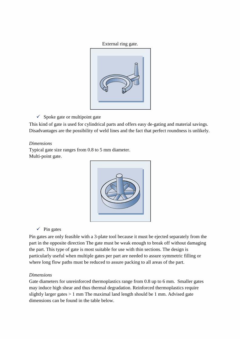
Spoke gate or multipoint gate
This kind of gate is used for cylindrical parts and offers easy de-gating and material savings.
Disadvantages are the possibility of weld lines and the fact that perfect roundness is unlikely.
Dimensions
Typical gate size ranges from 0.8 to 5 mm diameter.
Multi-point gate.
Pin gates
Pin gates are only feasible with a 3-plate tool because it must be ejected separately from the
part in the opposite direction The gate must be weak enough to break off without damaging
the part. This type of gate is most suitable for use with thin sections. The design is
particularly useful when multiple gates per part are needed to assure symmetric filling or
where long flow paths must be reduced to assure packing to all areas of the part.
Dimensions
Gate diameters for unreinforced thermoplastics range from 0.8 up to 6 mm. Smaller gates
may induce high shear and thus thermal degradation. Reinforced thermoplastics require
slightly larger gates > 1 mm The maximal land length should be 1 mm. Advised gate
dimensions can be found in the table below.
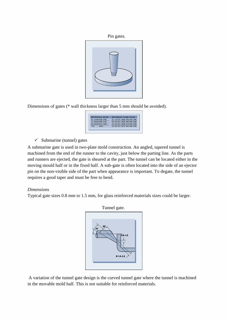
Pin gates.
Dimensions of gates (* wall thickness larger than 5 mm should be avoided).
Submarine (tunnel) gates
A submarine gate is used in two-plate mold construction. An angled, tapered tunnel is
machined from the end of the runner to the cavity, just below the parting line. As the parts
and runners are ejected, the gate is sheared at the part. The tunnel can be located either in the
moving mould half or in the fixed half. A sub-gate is often located into the side of an ejector
pin on the non-visible side of the part when appearance is important. To degate, the tunnel
requires a good taper and must be free to bend.
Dimensions
Typical gate sizes 0.8 mm to 1.5 mm, for glass reinforced materials sizes could be larger.
Tunnel gate.
A variation of the tunnel gate design is the curved tunnel gate where the tunnel is machined
in the movable mold half. This is not suitable for reinforced materials.
Curved tunnel gate.
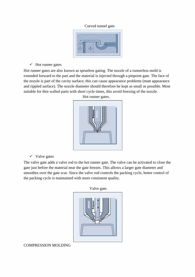
Hot runner gates
Hot runner gates are also known as sprueless gating. The nozzle of a runnerless mold is
extended forward to the part and the material is injected through a pinpoint gate. The face of
the nozzle is part of the cavity surface; this can cause appearance problems (matt appearance
and rippled surface). The nozzle diameter should therefore be kept as small as possible. Most
suitable for thin walled parts with short cycle times, this avoid freezing of the nozzle.
Hot runner gates.
Valve gates
The valve gate adds a valve rod to the hot runner gate. The valve can be activated to close the
gate just before the material near the gate freezes. This allows a larger gate diameter and
smoothes over the gate scar. Since the valve rod controls the packing cycle, better control of
the packing cycle is maintained with more consistent quality.
Valve gate.
COMPRESSION MOLDING

• Compression molding is the simplest method used for the production of elastomeric
materials. The term comes from the fact that the mold cavity compresses the material as it
closes, forming the part. Material is placed directly into the cavity then closed , put under
pressure (compressed) forcing the material to conform exactly to the cavity. The cure occurs
as the pressure and heat cause the thermoset material to crosslink.
• Materials that are typically manufactured :
Polyester fiberglass resin systems , Poly(pphenylene sulfide) (PPS), and many grades of
PEEK.
Products: FRP Nuts, Spacers, Step Blocks, Insulating Sheets,etc
Blow molding (also known as blow moulding or blow forming) is a manufacturing
process by which hollow plastic parts are formed. In general, there are three main types of
blow molding: extrusion blow molding, injection blow molding, and stretch blow molding.
The blow molding process begins with melting down the plastic and forming it into a parison
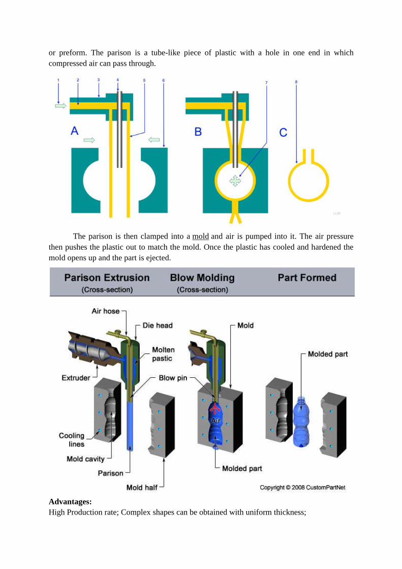
or preform. The parison is a tube-like piece of plastic with a hole in one end in which
compressed air can pass through.
The parison is then clamped into a mold and air is pumped into it. The air pressure
then pushes the plastic out to match the mold. Once the plastic has cooled and hardened the
mold opens up and the part is ejected.
Advantages:
High Production rate; Complex shapes can be obtained with uniform thickness;
Little scrap is generated.
Disadvantages:
Few material options; High tooling and equipment costs; Poor surface finish.
Limited to hollow shapes with thin wall and low degree of asymmetry.
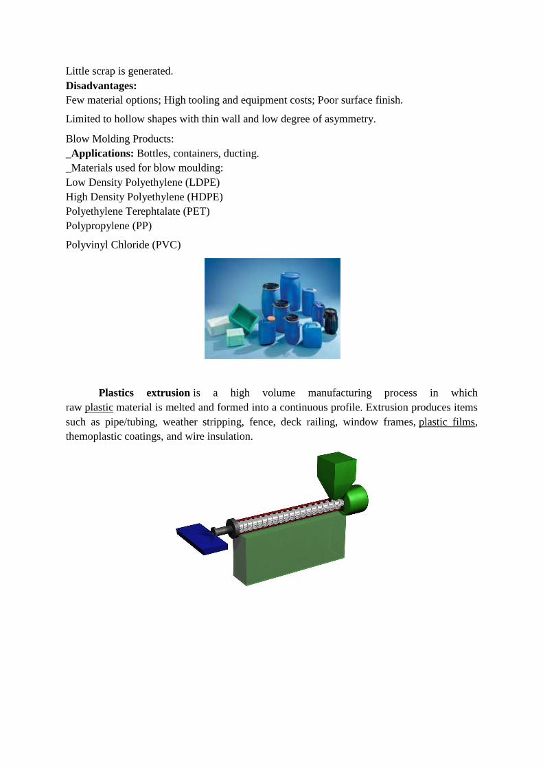
Blow Molding Products:
_Applications: Bottles, containers, ducting.
_Materials used for blow moulding:
Low Density Polyethylene (LDPE)
High Density Polyethylene (HDPE)
Polyethylene Terephtalate (PET)
Polypropylene (PP)
Polyvinyl Chloride (PVC)
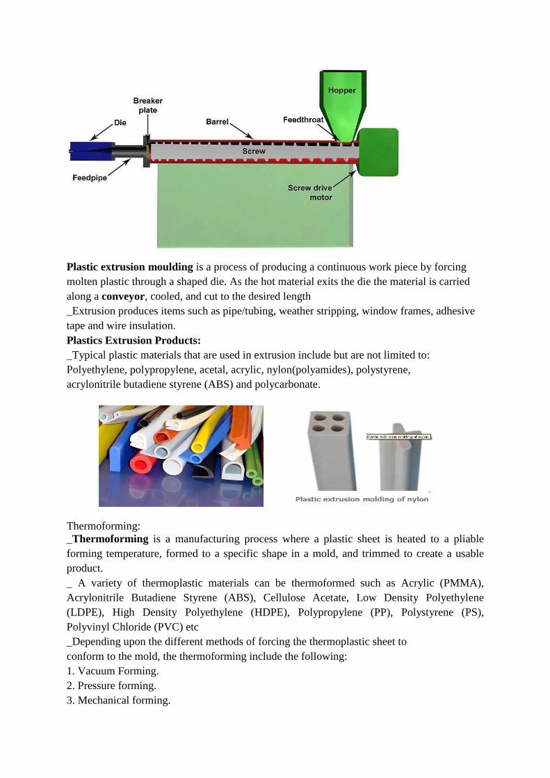
Plastics extrusion is a high volume manufacturing process in which
raw plastic material is melted and formed into a continuous profile. Extrusion produces items
such as pipe/tubing, weather stripping, fence, deck railing, window frames, plastic films,
themoplastic coatings, and wire insulation.
Plastic extrusion moulding is a process of producing a continuous work piece by forcing
molten plastic through a shaped die. As the hot material exits the die the material is carried
along a conveyor, cooled, and cut to the desired length
_Extrusion produces items such as pipe/tubing, weather stripping, window frames, adhesive
tape and wire insulation.
Plastics Extrusion Products:
_Typical plastic materials that are used in extrusion include but are not limited to:
Polyethylene, polypropylene, acetal, acrylic, nylon(polyamides), polystyrene,
acrylonitrile butadiene styrene (ABS) and polycarbonate.
Thermoforming:
_Thermoforming is a manufacturing process where a plastic sheet is heated to a pliable
forming temperature, formed to a specific shape in a mold, and trimmed to create a usable
product.
_ A variety of thermoplastic materials can be thermoformed such as Acrylic (PMMA),
Acrylonitrile Butadiene Styrene (ABS), Cellulose Acetate, Low Density Polyethylene
(LDPE), High Density Polyethylene (HDPE), Polypropylene (PP), Polystyrene (PS),
Polyvinyl Chloride (PVC) etc
_Depending upon the different methods of forcing the thermoplastic sheet to
conform to the mold, the thermoforming include the following:
1. Vacuum Forming.
2. Pressure forming.
3. Mechanical forming.
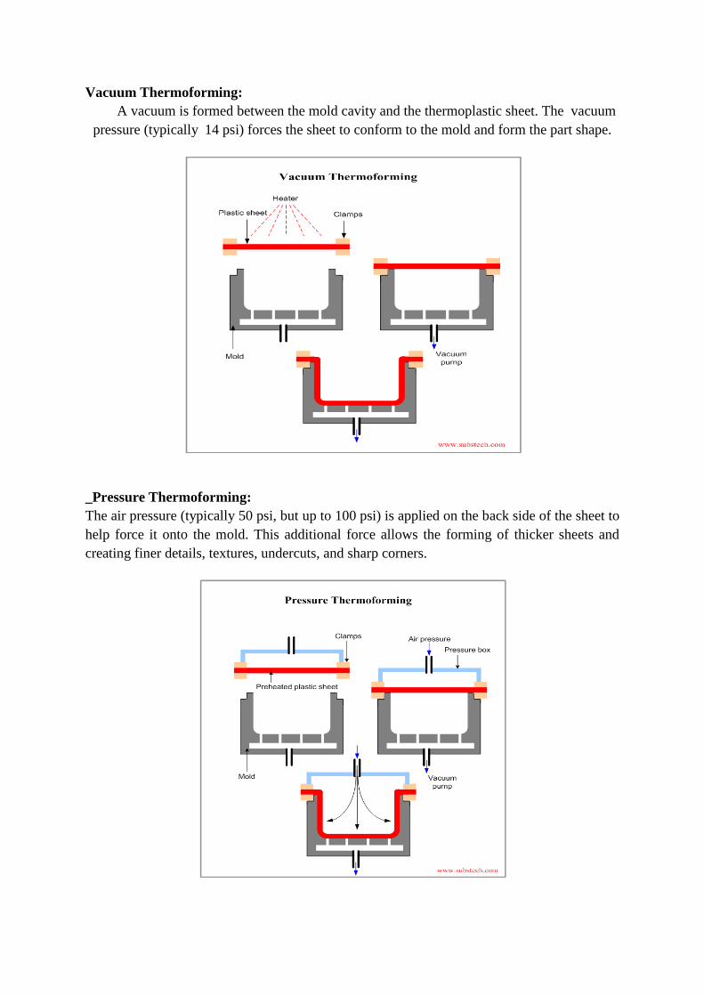
Vacuum Thermoforming:
A vacuum is formed between the mold cavity and the thermoplastic sheet. The vacuum
pressure (typically 14 psi) forces the sheet to conform to the mold and form the part shape.
_Pressure Thermoforming:
The air pressure (typically 50 psi, but up to 100 psi) is applied on the back side of the sheet to
help force it onto the mold. This additional force allows the forming of thicker sheets and
creating finer details, textures, undercuts, and sharp corners.
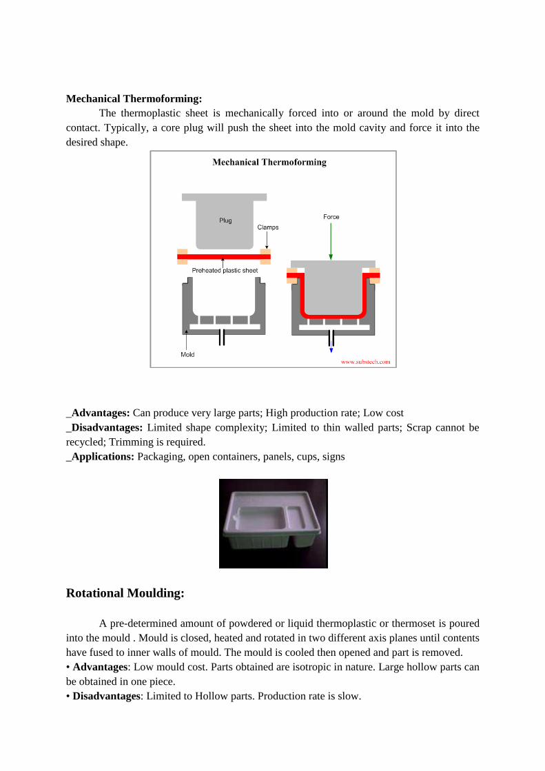
Mechanical Thermoforming:
The thermoplastic sheet is mechanically forced into or around the mold by direct
contact. Typically, a core plug will push the sheet into the mold cavity and force it into the
desired shape.
_Advantages: Can produce very large parts; High production rate; Low cost
_Disadvantages: Limited shape complexity; Limited to thin walled parts; Scrap cannot be
recycled; Trimming is required.
_Applications: Packaging, open containers, panels, cups, signs
Rotational Moulding:
A pre-determined amount of powdered or liquid thermoplastic or thermoset is poured
into the mould . Mould is closed, heated and rotated in two different axis planes until contents
have fused to inner walls of mould. The mould is cooled then opened and part is removed.
• Advantages: Low mould cost. Parts obtained are isotropic in nature. Large hollow parts can
be obtained in one piece.
• Disadvantages: Limited to Hollow parts. Production rate is slow.
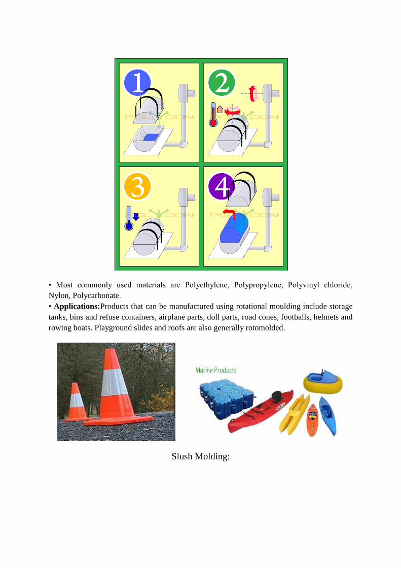
• Most commonly used materials are Polyethylene, Polypropylene, Polyvinyl chloride,
Nylon, Polycarbonate.
• Applications:Products that can be manufactured using rotational moulding include storage
tanks, bins and refuse containers, airplane parts, doll parts, road cones, footballs, helmets and
rowing boats. Playground slides and roofs are also generally rotomolded.
Slush Molding:
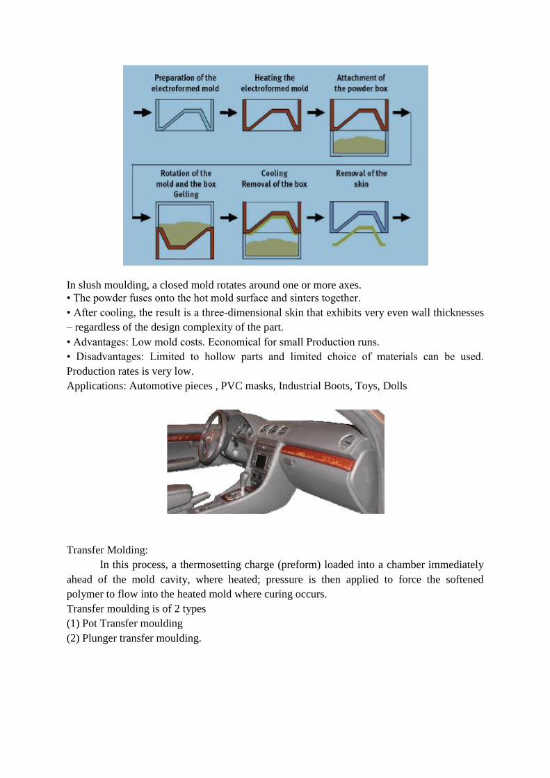
In slush moulding, a closed mold rotates around one or more axes.
• The powder fuses onto the hot mold surface and sinters together.
• After cooling, the result is a three-dimensional skin that exhibits very even wall thicknesses
– regardless of the design complexity of the part.
• Advantages: Low mold costs. Economical for small Production runs.
• Disadvantages: Limited to hollow parts and limited choice of materials can be used.
Production rates is very low.
Applications: Automotive pieces , PVC masks, Industrial Boots, Toys, Dolls
Transfer Molding:
In this process, a thermosetting charge (preform) loaded into a chamber immediately
ahead of the mold cavity, where heated; pressure is then applied to force the softened
polymer to flow into the heated mold where curing occurs.
Transfer moulding is of 2 types
(1) Pot Transfer moulding
(2) Plunger transfer moulding.
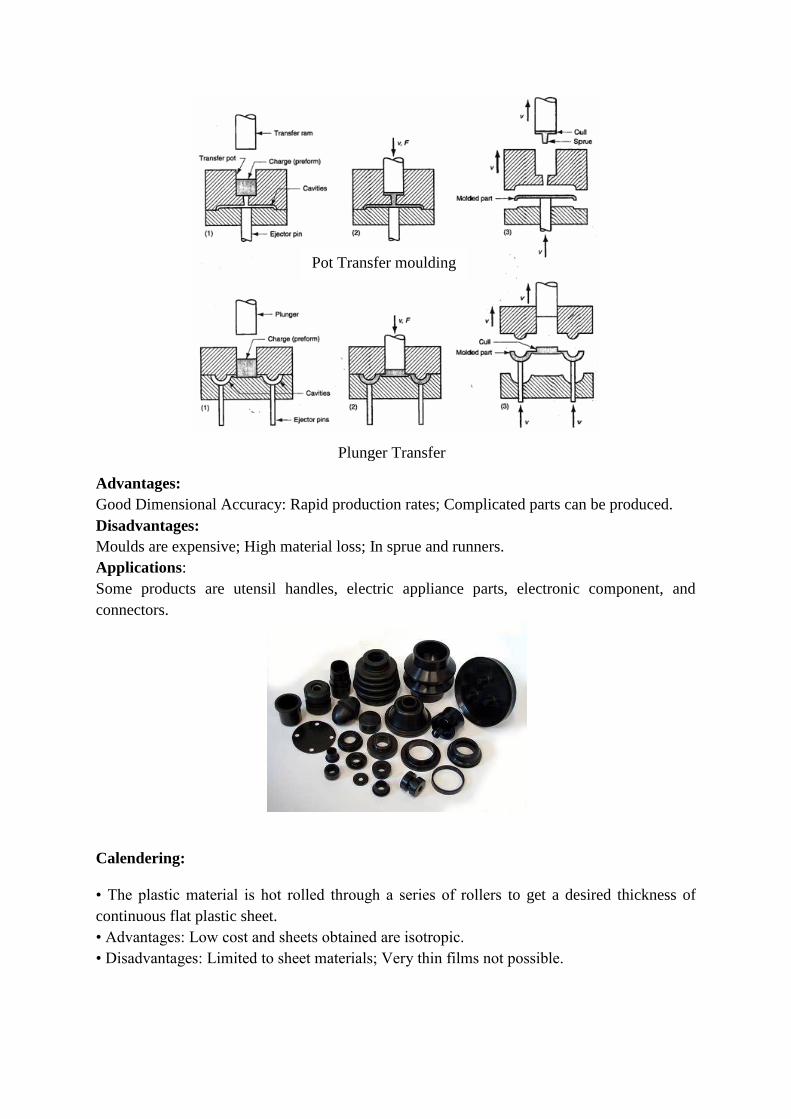
Advantages:
Good Dimensional Accuracy: Rapid production rates; Complicated parts can be produced.
Disadvantages:
Moulds are expensive; High material loss; In sprue and runners.
Applications:
Some products are utensil handles, electric appliance parts, electronic component, and
connectors.
Calendering:
• The plastic material is hot rolled through a series of rollers to get a desired thickness of
continuous flat plastic sheet.
• Advantages: Low cost and sheets obtained are isotropic.
• Disadvantages: Limited to sheet materials; Very thin films not possible.
Pot Transfer moulding
Plunger Transfer
moulding

Design Rules For Plastic Parts:
• Maximum wall thickness
• Corners
• Draft
• Ribs
• Bosses
• Undercuts
• Threads
Wall Thickness
If there was only one rule for the injection moulding process it would have to be "maintain
uniform wall thickness".
10% increase in the wall thickness provides appx. 33% increase in the stiffness. But
increasing wall thickness also add to part weight, cycle time and material cost.
Changing the wall thickness after mold design will be too expensive.
Normal range of wall thickness
The vast majority of injection molded parts wall thickness range from 0.8 mm to 4.8 mm!
Nominal wall thickness should not exceed 4.0 mm.
Walls thicker than 4.0 mm will result in increased cycle times (due to the longer time
required for cooling), will increase the likelihood of voids and significantly decrease the
physical properties of the part.
A wall thickness variation of ±25% is acceptable in a part made with a thermoplastic having a
shrinkage rate of less than 0.01 mm/mm. If the shrinkage rate exceeds 0.01 mm/mm, then a
thickness variation of ±15% is permissible
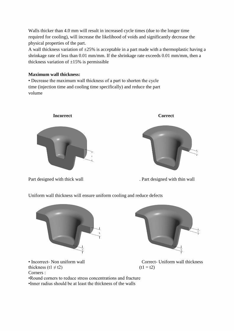
Maximum wall thickness:
• Decrease the maximum wall thickness of a part to shorten the cycle
time (injection time and cooling time specifically) and reduce the part
volume
Incorrect Correct
Part designed with thick wall . Part designed with thin wall
Uniform wall thickness will ensure uniform cooling and reduce defects
• Incorrect- Non uniform wall Correct- Uniform wall thickness
thickness (t1 ≠ t2) (t1 = t2)
Corners :
•Round corners to reduce stress concentrations and fracture
•Inner radius should be at least the thickness of the walls

Incorrect- Sharp corners Correct- Filleted corners.
Draft :
Apply a draft angle of 1°- 2°to all walls parallel t o the parting direction to facilitate removing
the part from the mold.
Incorrect- No Draft angle Correct- With Draft angle.
Ribs :
Ribs provide a means to economically augment stiffness and strength in moulded parts
without increasing overall wall thickness.
•Locating and captivation components of an assembly
•Providing alignment in mating parts
•Acting as stops or guides for mechanisms Consideration for Rib Design: Thickness Height
Location Quantity Moldability
•Add ribs for structural support, rather than increasing the wall thickness

Incorrect- Thick wall of thickness t Correct- Thin walled ribs of thickness t
•Orient ribs perpendicular to the axis about which bending may occur.
Incorrect- Rib direction under load F Correct- Rib direction under load F
•Thickness of ribs should be 50-60% of the walls to which they are attached
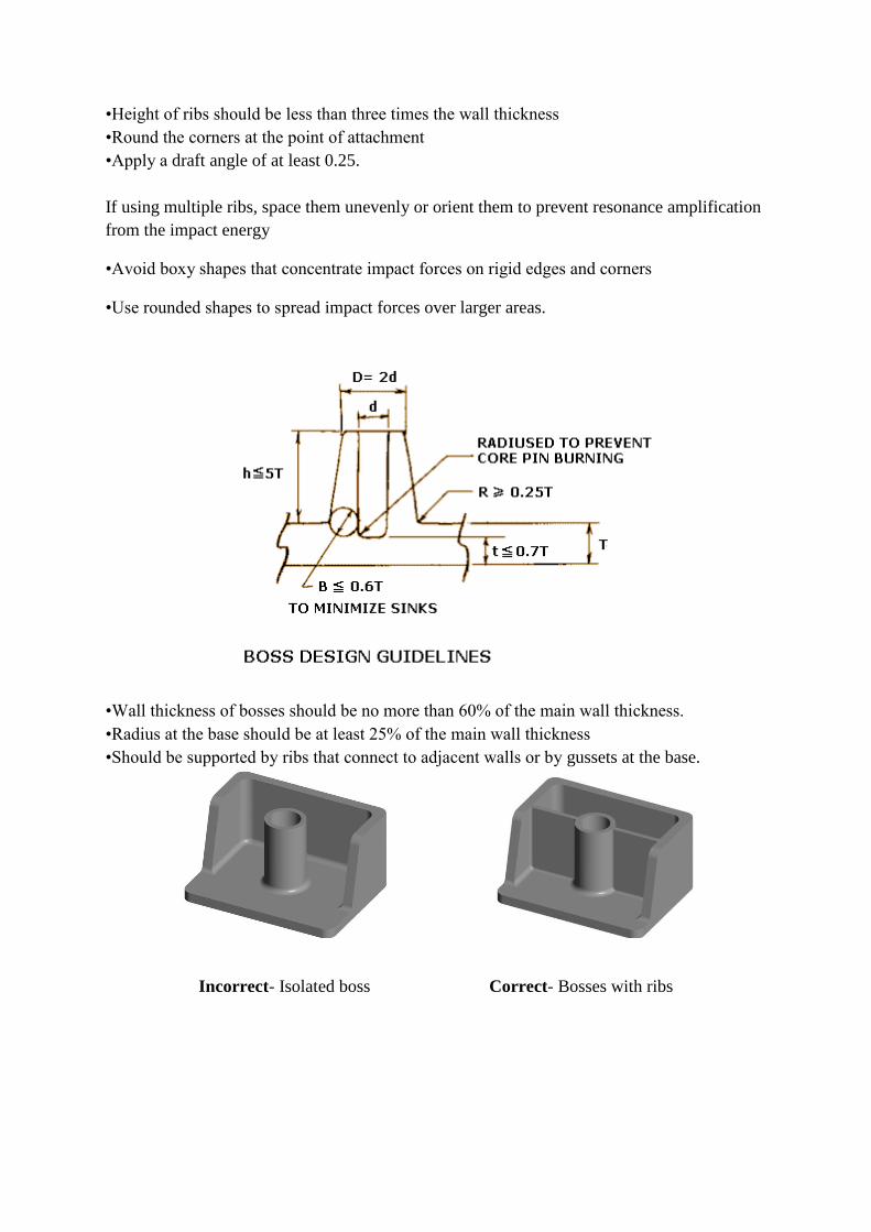
•Height of ribs should be less than three times the wall thickness
•Round the corners at the point of attachment
•Apply a draft angle of at least 0.25.
If using multiple ribs, space them unevenly or orient them to prevent resonance amplification
from the impact energy
•Avoid boxy shapes that concentrate impact forces on rigid edges and corners
•Use rounded shapes to spread impact forces over larger areas.
•Wall thickness of bosses should be no more than 60% of the main wall thickness.
•Radius at the base should be at least 25% of the main wall thickness
•Should be supported by ribs that connect to adjacent walls or by gussets at the base.
Incorrect- Isolated boss Correct- Bosses with ribs
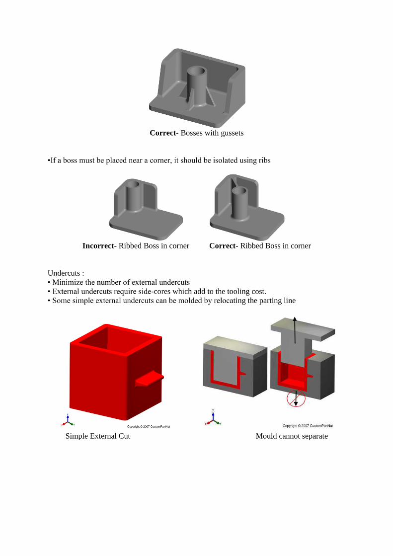
Correct- Bosses with gussets
•If a boss must be placed near a corner, it should be isolated using ribs
Incorrect- Ribbed Boss in corner Correct- Ribbed Boss in corner
Undercuts :
• Minimize the number of external undercuts
• External undercuts require side-cores which add to the tooling cost.
• Some simple external undercuts can be molded by relocating the parting line
Simple External Cut Mould cannot separate

New parting line allows undercut
Redesigning a feature can remove an external undercut
Part with hinge Hinge requires side-core
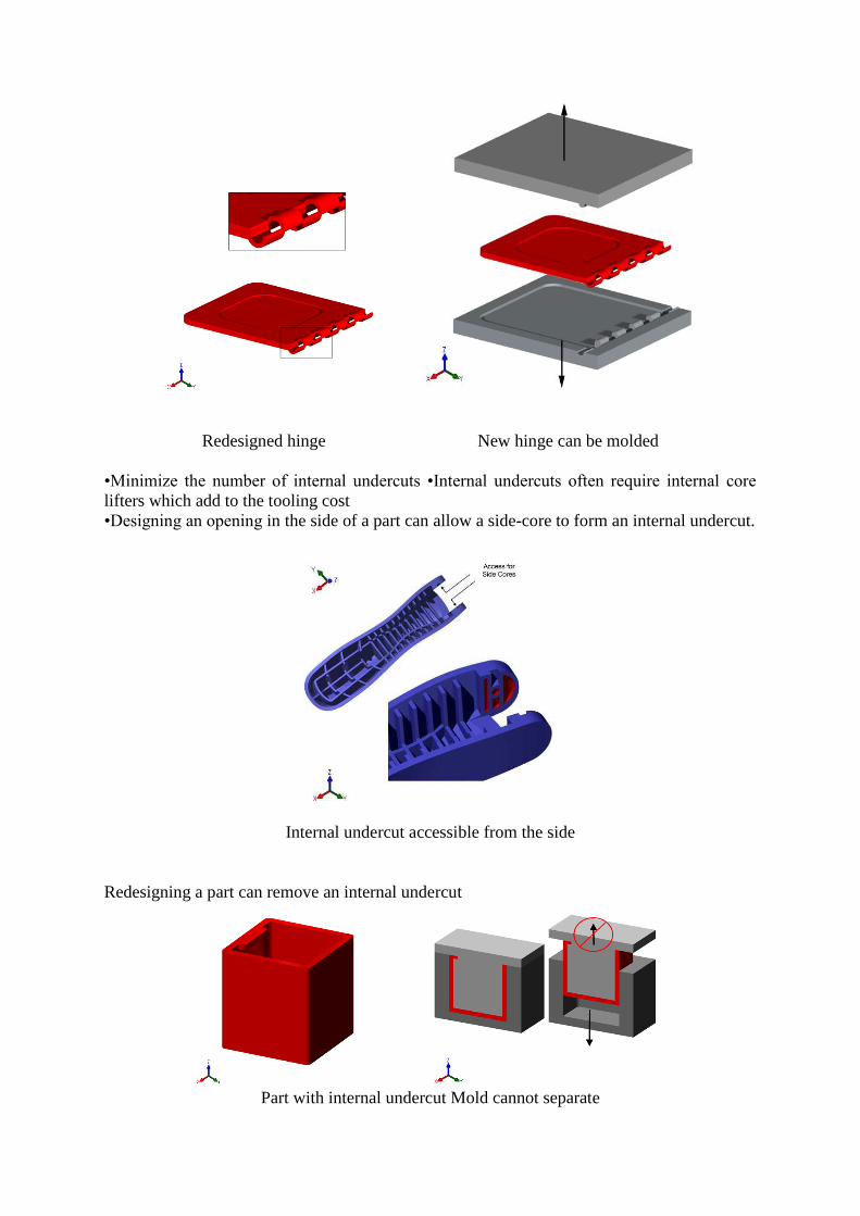
Redesigned hinge New hinge can be molded
•Minimize the number of internal undercuts •Internal undercuts often require internal core
lifters which add to the tooling cost
•Designing an opening in the side of a part can allow a side-core to form an internal undercut.
Internal undercut accessible from the side
Redesigning a part can remove an internal undercut
Part with internal undercut Mold cannot separate
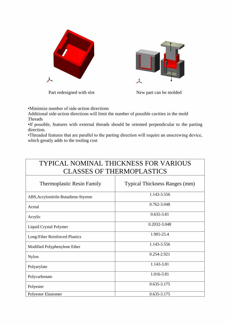
Part redesigned with slot New part can be molded
•Minimize number of side-action directions
Additional side-action directions will limit the number of possible cavities in the mold
Threads
•If possible, features with external threads should be oriented perpendicular to the parting
direction.
•Threaded features that are parallel to the parting direction will require an unscrewing device,
which greatly adds to the tooling cost
TYPICAL NOMINAL THICKNESS FOR VARIOUS
CLASSES OF THERMOPLASTICS
Thermoplastic Resin Family Typical Thickness Ranges (mm)
ABS,Acrylonitrile-Butadiene-Styrene 1.143-3.556
Acetal 0.762-3.048
Acrylic 0.635-3.81
Liquid Crystal Polymer 0.2032-3.048
Long-Fiber Reinforced Plastics 1.905-25.4
Modified Polyphenylene Ether 1.143-3.556
Nylon 0.254-2.921
Polyarylate 1.143-3.81
Polycarbonate 1.016-3.81
Polyester 0.635-3.175
Polyester Elastomer 0.635-3.175
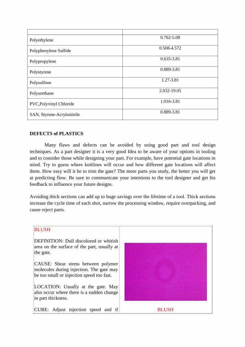
Polyethylene 0.762-5.08
Polyphenylene Sulfide 0.508-4.572
Polypropylene 0.635-3.81
Polystyrene 0.889-3.81
Polysulfone 1.27-3.81
Polyurethane 2.032-19.05
PVC,Polyvinyl Chloride 1.016-3.81
SAN, Styrene-Acrylonitrile 0.889-3.81
DEFECTS of PLASTICS
Many flaws and defects can be avoided by using good part and tool design
techniques. As a part designer it is a very good Idea to be aware of your options in tooling
and to consider those while designing your part. For example, have potential gate locations in
mind. Try to guess where knitlines will occur and how different gate locations will affect
them. How easy will it be to trim the gate? The more parts you study, the better you will get
at predicting flow. Be sure to communicate your intentions to the tool designer and get his
feedback to influence your future designs.
Avoiding thick sections can add up to huge savings over the lifetime of a tool. Thick sections
increase the cycle time of each shot, narrow the processing window, require overpacking, and
cause reject parts.
BLUSH
DEFINITION: Dull discolored or whitish
area on the surface of the part, usually at
the gate.
CAUSE: Shear stress between polymer
molecules during injection. The gate may
be too small or injection speed too fast.
LOCATION: Usually at the gate. May
also occur where there is a sudden change
in part thickness.
CURE: Adjust injection speed and if
BLUSH

necessary adjust gate dimensions. An
independent water circuit in the mold that
allows pinpoint temperature control at the
gate can also help.
BURN
DEFINITION: Discoloration usually
black, brown or dark yellow/brown
depending upon severity. Feels rough and
crunchy. Frequently accompanied by
short shot in burn area.
CAUSE: Usually indicates a need for
more venting or heat buildup in tool.
When air is trapped in the tool and cannot
escape, the extreme pressure causes the
air to ignite, burning the edge of the part.
LOCATION: Most often seen in deep,
blind ribs where a lot of air can be forced
into a small space.
CURE: Add more parting line vents near
burn or vent pins in deep ribs. Vent pins
are just ejector pins that fit a little loose.
They may also have a flat ground down
one side to let the air escape.
BURN
COLD FLOW
DEFINITION: Wavy or streaked
appearance on part surface. Looks like a
fingerprint or small waves like you would
see on the surface of water.
CAUSE: Low melt temperature, low
injection speed or low injection pressure.
LOCATION: Hard to fill or last to fill
areas.
COLD FLOW
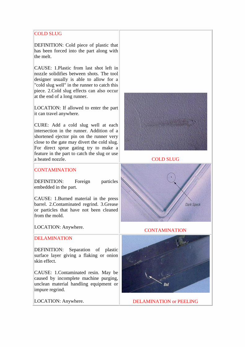
COLD SLUG
DEFINITION: Cold piece of plastic that
has been forced into the part along with
the melt.
CAUSE: 1.Plastic from last shot left in
nozzle solidifies between shots. The tool
designer usually is able to allow for a
"cold slug well" in the runner to catch this
piece. 2.Cold slug effects can also occur
at the end of a long runner.
LOCATION: If allowed to enter the part
it can travel anywhere.
CURE: Add a cold slug well at each
intersection in the runner. Addition of a
shortened ejector pin on the runner very
close to the gate may divert the cold slug.
For direct sprue gating try to make a
feature in the part to catch the slug or use
a heated nozzle.
COLD SLUG
CONTAMINATION
DEFINITION: Foreign particles
embedded in the part.
CAUSE: 1.Burned material in the press
barrel. 2.Contaminated regrind. 3.Grease
or particles that have not been cleaned
from the mold.
LOCATION: Anywhere.
CONTAMINATION
DELAMINATION
DEFINITION: Separation of plastic
surface layer giving a flaking or onion
skin effect.
CAUSE: 1.Contaminated resin. May be
caused by incomplete machine purging,
unclean material handling equipment or
impure regrind.
LOCATION: Anywhere.
DELAMINATION or PEELING
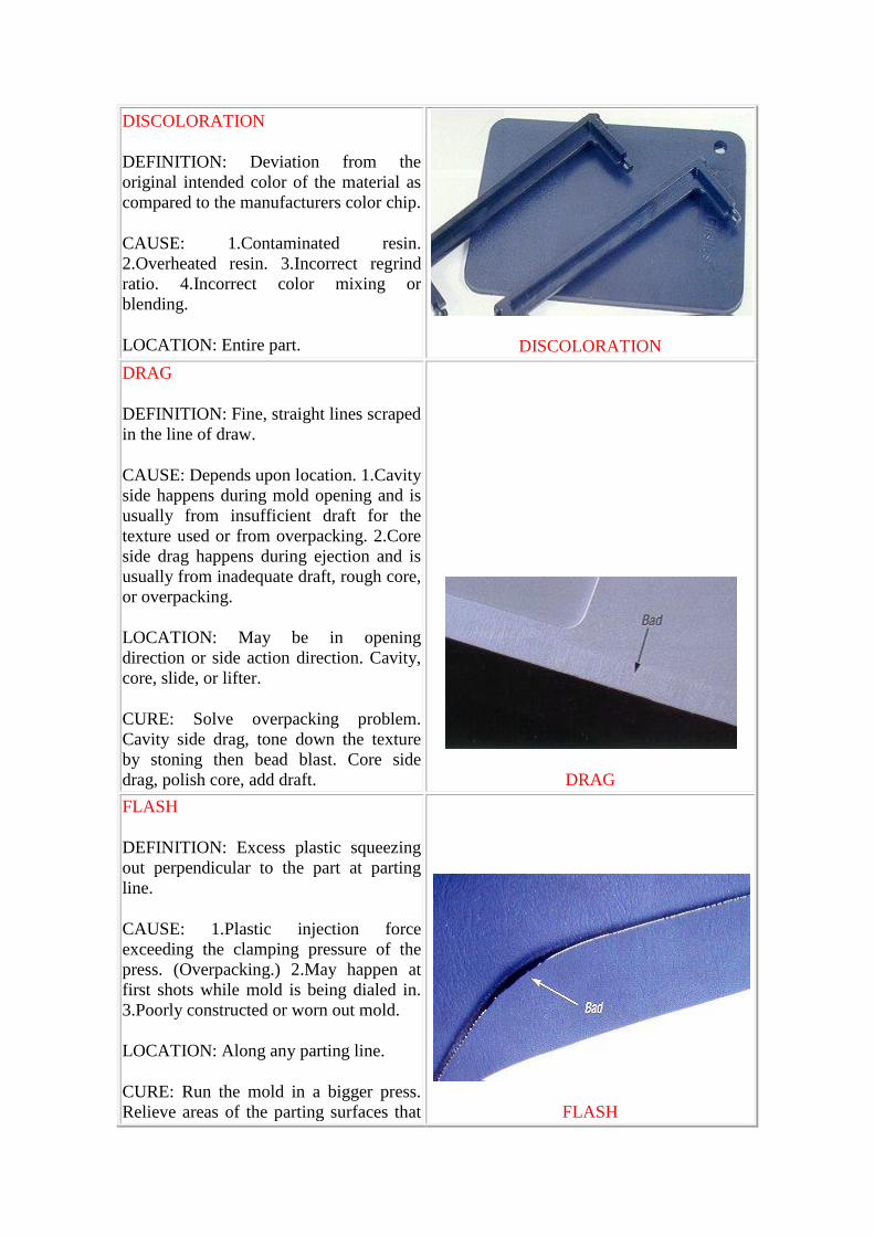
DISCOLORATION
DEFINITION: Deviation from the
original intended color of the material as
compared to the manufacturers color chip.
CAUSE: 1.Contaminated resin.
2.Overheated resin. 3.Incorrect regrind
ratio. 4.Incorrect color mixing or
blending.
LOCATION: Entire part.
DISCOLORATION
DRAG
DEFINITION: Fine, straight lines scraped
in the line of draw.
CAUSE: Depends upon location. 1.Cavity
side happens during mold opening and is
usually from insufficient draft for the
texture used or from overpacking. 2.Core
side drag happens during ejection and is
usually from inadequate draft, rough core,
or overpacking.
LOCATION: May be in opening
direction or side action direction. Cavity,
core, slide, or lifter.
CURE: Solve overpacking problem.
Cavity side drag, tone down the texture
by stoning then bead blast. Core side
drag, polish core, add draft.
DRAG
FLASH
DEFINITION: Excess plastic squeezing
out perpendicular to the part at parting
line.
CAUSE: 1.Plastic injection force
exceeding the clamping pressure of the
press. (Overpacking.) 2.May happen at
first shots while mold is being dialed in.
3.Poorly constructed or worn out mold.
LOCATION: Along any parting line.
CURE: Run the mold in a bigger press.
Relieve areas of the parting surfaces that
FLASH

are not immediately adjacent to the part.
Leave 0.500 in. of shutoff land around the
part.
GLOSS
DEFINITION: Smooth shiny areas on the
part surface.
CAUSE: 1.Underpacking 2.See section
on plateout below.
LOCATION: Hard to fill areas.
GLOSS
JETTING
DEFINITION: Squiggly line in part
pointing to gate. Looks like a worm in the
part.
CAUSE: 1.Incorrect gate placement or
size. The gate is positioned in such a
manner as to aim the plastic straight into
an open area. The plastic launches out
into the open like a piece of "silly string"
and then stacks up in squiggles.
LOCATION: Near gate.
CURE: Aim the gate at an obstacle that
interrupts the flow. Use different gate
style or larger gate.
JETTING
KNITLINE
DEFINITION: A line where the molten
polymer flow fronts meet in the mold.
Incomplete adhesion occurs along the
knitline and causes a weak point in the
plastic part.
CAUSE: Cold fronts meeting in the tool
where molten plastic fronts meet.
LOCATION: Cold fronts meeting in the
tool where plastic flows around obstacles
or over raised areas in the metal. It is
guaranteed that you will have a knitline as
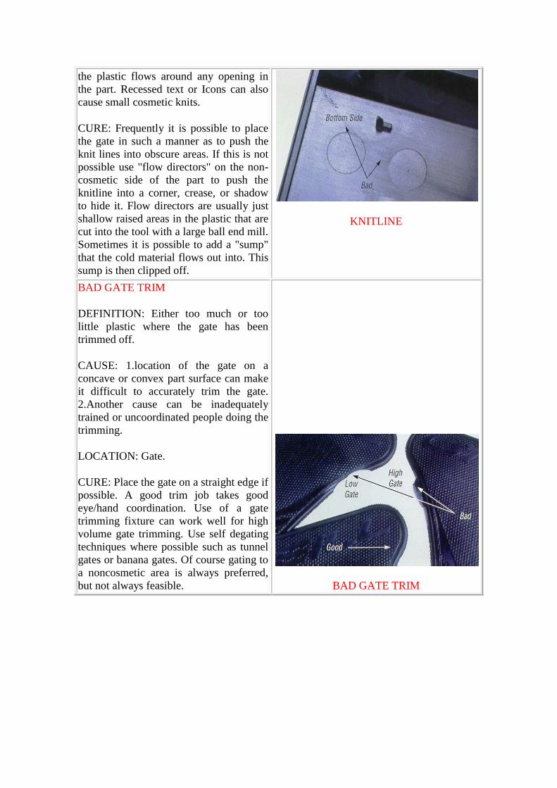
the plastic flows around any opening in
the part. Recessed text or Icons can also
cause small cosmetic knits.
CURE: Frequently it is possible to place
the gate in such a manner as to push the
knit lines into obscure areas. If this is not
possible use "flow directors" on the non-
cosmetic side of the part to push the
knitline into a corner, crease, or shadow
to hide it. Flow directors are usually just
shallow raised areas in the plastic that are
cut into the tool with a large ball end mill.
Sometimes it is possible to add a "sump"
that the cold material flows out into. This
sump is then clipped off.
KNITLINE
BAD GATE TRIM
DEFINITION: Either too much or too
little plastic where the gate has been
trimmed off.
CAUSE: 1.location of the gate on a
concave or convex part surface can make
it difficult to accurately trim the gate.
2.Another cause can be inadequately
trained or uncoordinated people doing the
trimming.
LOCATION: Gate.
CURE: Place the gate on a straight edge if
possible. A good trim job takes good
eye/hand coordination. Use of a gate
trimming fixture can work well for high
volume gate trimming. Use self degating
techniques where possible such as tunnel
gates or banana gates. Of course gating to
a noncosmetic area is always preferred,
but not always feasible.
BAD GATE TRIM
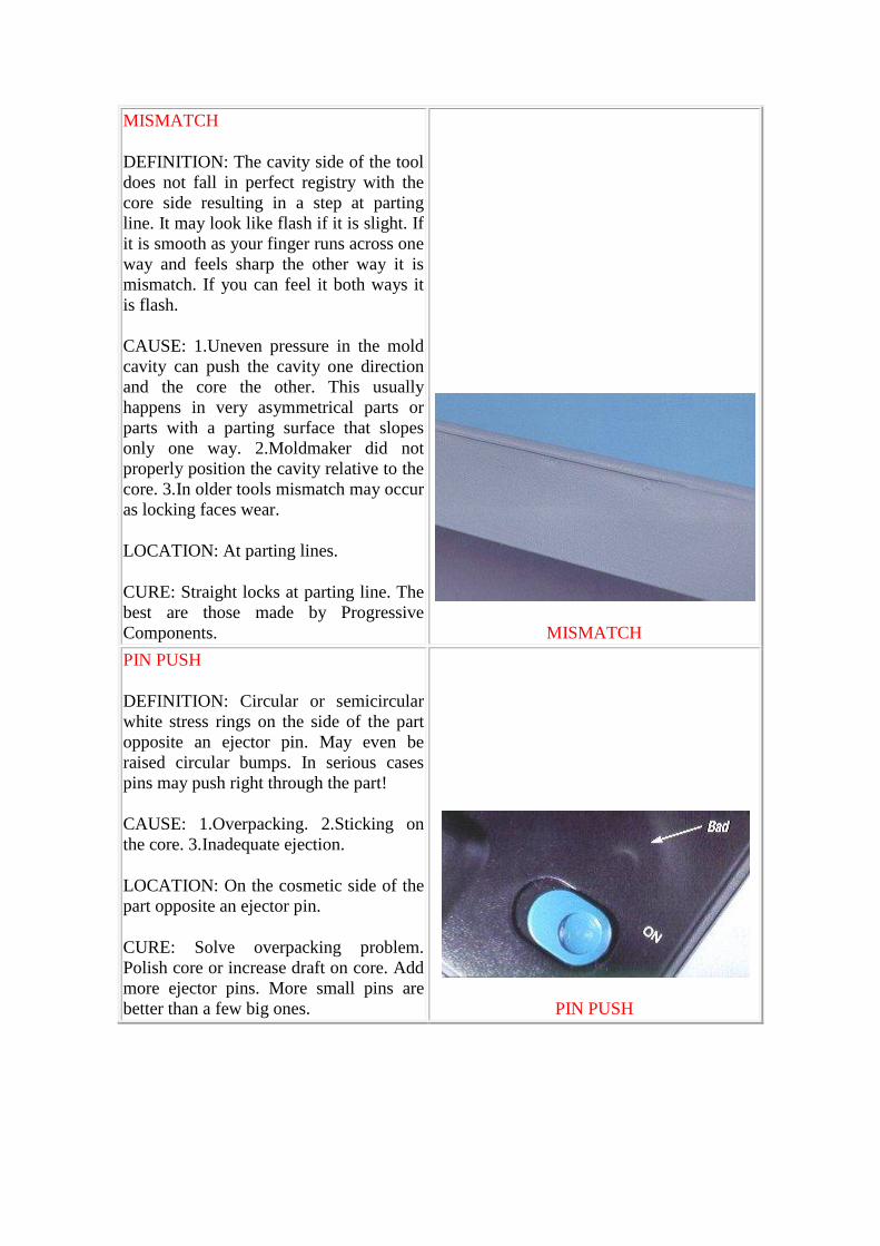
MISMATCH
DEFINITION: The cavity side of the tool
does not fall in perfect registry with the
core side resulting in a step at parting
line. It may look like flash if it is slight. If
it is smooth as your finger runs across one
way and feels sharp the other way it is
mismatch. If you can feel it both ways it
is flash.
CAUSE: 1.Uneven pressure in the mold
cavity can push the cavity one direction
and the core the other. This usually
happens in very asymmetrical parts or
parts with a parting surface that slopes
only one way. 2.Moldmaker did not
properly position the cavity relative to the
core. 3.In older tools mismatch may occur
as locking faces wear.
LOCATION: At parting lines.
CURE: Straight locks at parting line. The
best are those made by Progressive
Components.
MISMATCH
PIN PUSH
DEFINITION: Circular or semicircular
white stress rings on the side of the part
opposite an ejector pin. May even be
raised circular bumps. In serious cases
pins may push right through the part!
CAUSE: 1.Overpacking. 2.Sticking on
the core. 3.Inadequate ejection.
LOCATION: On the cosmetic side of the
part opposite an ejector pin.
CURE: Solve overpacking problem.
Polish core or increase draft on core. Add
more ejector pins. More small pins are
better than a few big ones.
PIN PUSH
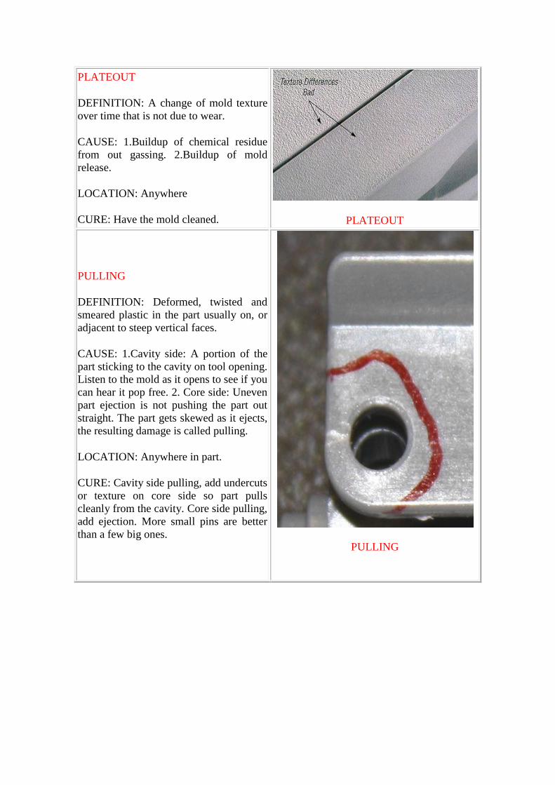
PLATEOUT
DEFINITION: A change of mold texture
over time that is not due to wear.
CAUSE: 1.Buildup of chemical residue
from out gassing. 2.Buildup of mold
release.
LOCATION: Anywhere
CURE: Have the mold cleaned.
PLATEOUT
PULLING
DEFINITION: Deformed, twisted and
smeared plastic in the part usually on, or
adjacent to steep vertical faces.
CAUSE: 1.Cavity side: A portion of the
part sticking to the cavity on tool opening.
Listen to the mold as it opens to see if you
can hear it pop free. 2. Core side: Uneven
part ejection is not pushing the part out
straight. The part gets skewed as it ejects,
the resulting damage is called pulling.
LOCATION: Anywhere in part.
CURE: Cavity side pulling, add undercuts
or texture on core side so part pulls
cleanly from the cavity. Core side pulling,
add ejection. More small pins are better
than a few big ones.
PULLING
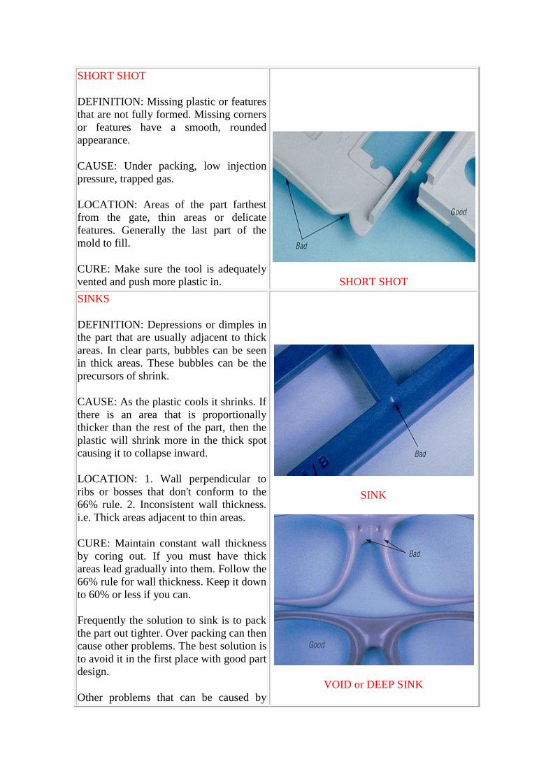
SHORT SHOT
DEFINITION: Missing plastic or features
that are not fully formed. Missing corners
or features have a smooth, rounded
appearance.
CAUSE: Under packing, low injection
pressure, trapped gas.
LOCATION: Areas of the part farthest
from the gate, thin areas or delicate
features. Generally the last part of the
mold to fill.
CURE: Make sure the tool is adequately
vented and push more plastic in.
SHORT SHOT
SINKS
DEFINITION: Depressions or dimples in
the part that are usually adjacent to thick
areas. In clear parts, bubbles can be seen
in thick areas. These bubbles can be the
precursors of shrink.
CAUSE: As the plastic cools it shrinks. If
there is an area that is proportionally
thicker than the rest of the part, then the
plastic will shrink more in the thick spot
causing it to collapse inward.
LOCATION: 1. Wall perpendicular to
ribs or bosses that don't conform to the
66% rule. 2. Inconsistent wall thickness.
i.e. Thick areas adjacent to thin areas.
CURE: Maintain constant wall thickness
by coring out. If you must have thick
areas lead gradually into them. Follow the
66% rule for wall thickness. Keep it down
to 60% or less if you can.
Frequently the solution to sink is to pack
the part out tighter. Over packing can then
cause other problems. The best solution is
to avoid it in the first place with good part
design.
Other problems that can be caused by
SINK
VOID or DEEP SINK
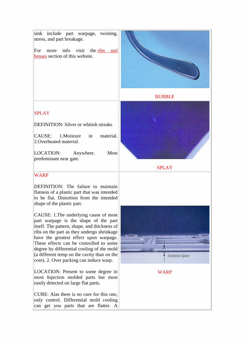
sink include part warpage, twisting,
stress, and part breakage.
For more info visit the ribs and
bosses section of this website.
BUBBLE
SPLAY
DEFINITION: Silver or whitish streaks
CAUSE: 1.Moisture in material.
2.Overheated material.
LOCATION: Anywhere. Most
predominant near gate.
SPLAY
WARP
DEFINITION: The failure to maintain
flatness of a plastic part that was intended
to be flat. Distortion from the intended
shape of the plastic part.
CAUSE: 1.The underlying cause of most
part warpage is the shape of the part
itself. The pattern, shape, and thickness of
ribs on the part as they undergo shrinkage
have the greatest effect upon warpage.
These effects can be controlled to some
degree by differential cooling of the mold
(a different temp on the cavity than on the
core). 2. Over packing can induce warp.
LOCATION: Present to some degree in
most Injection molded parts but most
easily detected on large flat parts.
CURE: Alas there is no cure for this one,
only control. Differential mold cooling
can get you parts that are flatter. A
WARP
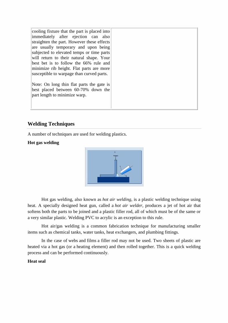
cooling fixture that the part is placed into
immediately after ejection can also
straighten the part. However these effects
are usually temporary and upon being
subjected to elevated temps or time parts
will return to their natural shape. Your
best bet is to follow the 66% rule and
minimize rib height. Flat parts are more
susceptible to warpage than curved parts.
Note: On long thin flat parts the gate is
best placed between 60-70% down the
part length to minimize warp.
Welding Techniques
A number of techniques are used for welding plastics.
Hot gas welding
Hot gas welding, also known as hot air welding, is a plastic welding technique using
heat. A specially designed heat gun, called a hot air welder, produces a jet of hot air that
softens both the parts to be joined and a plastic filler rod, all of which must be of the same or
a very similar plastic. Welding PVC to acrylic is an exception to this rule.
Hot air/gas welding is a common fabrication technique for manufacturing smaller
items such as chemical tanks, water tanks, heat exchangers, and plumbing fittings.
In the case of webs and films a filler rod may not be used. Two sheets of plastic are
heated via a hot gas (or a heating element) and then rolled together. This is a quick welding
process and can be performed continuously.
Heat seal

A variety of heat sealers are available to join thermoplastic materials such as plastic
films: Hot bar sealer, Impulse sealer, etc.
Freehand welding
With freehand welding, the jet of hot air (or inert gas) from the welder is played on
the weld area and the tip of the weld rod at the same time. As the rod softens, it is pushed into
the joint and fuses to the parts. This process is slower than most others, but it can be used in
almost any situation.
Speed tip welding
With speed welding, the plastic welder, similar to a soldering iron in appearance and
wattage, is fitted with a feed tube for the plastic weld rod. The speed tip heats the rod and the
substrate, while at the same time it presses the molten weld rod into position.
A bead of softened plastic is laid into the joint, and the parts and weld rod fuse. With
some types of plastic such as polypropylene, the melted welding rod must be "mixed" with

the semi-melted base material being fabricated or repaired. These welding techniques have
been perfected over time and have been utilised for over 50 years by professional plastic
fabricators and repairers internationally. Speed tip welding method is a much faster welding
technique and with practice can be used in tight corners. A version of the speed tip "gun" is
essentially a soldering iron with a broad, flat tip that can be used to melt the weld joint and
filler materiel to create a bond.
Extrusion welding
Extrusion welding allows the application of bigger welds in a single weld pass. It is
the preferred technique for joining material over 6 mm thick. Welding rod is drawn into a
miniature hand held plastic extruder, plasticized, and forced out of the extruder against the
parts being joined, which are softened with a jet of hot air to allow bonding to take place.
Contact welding
This is the same as spot welding except that heat is supplied with conduction of the
pincher tips instead of electrical conduction. Two plastic parts are brought together where
heated tips pinch them, melting and joining the parts in the process.
Hot plate welding
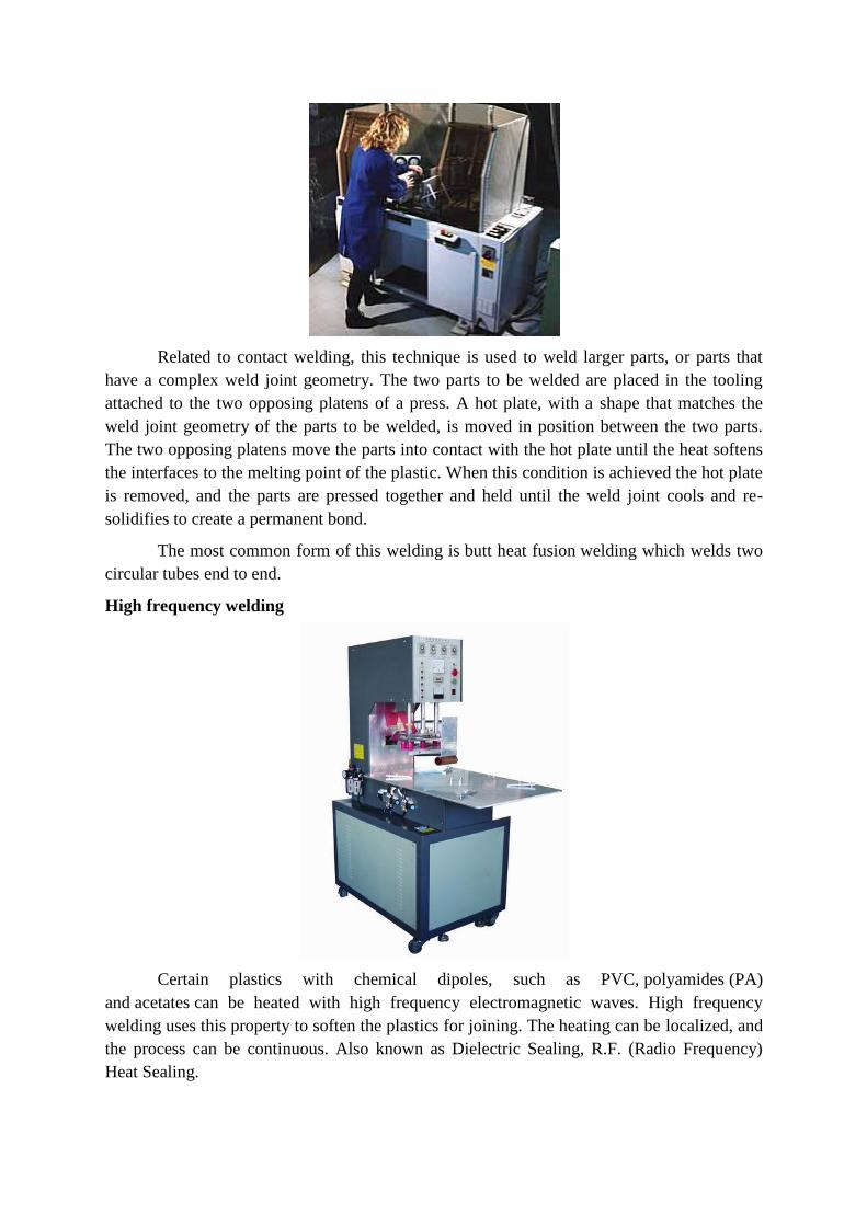
Related to contact welding, this technique is used to weld larger parts, or parts that
have a complex weld joint geometry. The two parts to be welded are placed in the tooling
attached to the two opposing platens of a press. A hot plate, with a shape that matches the
weld joint geometry of the parts to be welded, is moved in position between the two parts.
The two opposing platens move the parts into contact with the hot plate until the heat softens
the interfaces to the melting point of the plastic. When this condition is achieved the hot plate
is removed, and the parts are pressed together and held until the weld joint cools and re-
solidifies to create a permanent bond.
The most common form of this welding is butt heat fusion welding which welds two
circular tubes end to end.
High frequency welding
Certain plastics with chemical dipoles, such as PVC, polyamides (PA)
and acetates can be heated with high frequency electromagnetic waves. High frequency
welding uses this property to soften the plastics for joining. The heating can be localized, and
the process can be continuous. Also known as Dielectric Sealing, R.F. (Radio Frequency)
Heat Sealing.
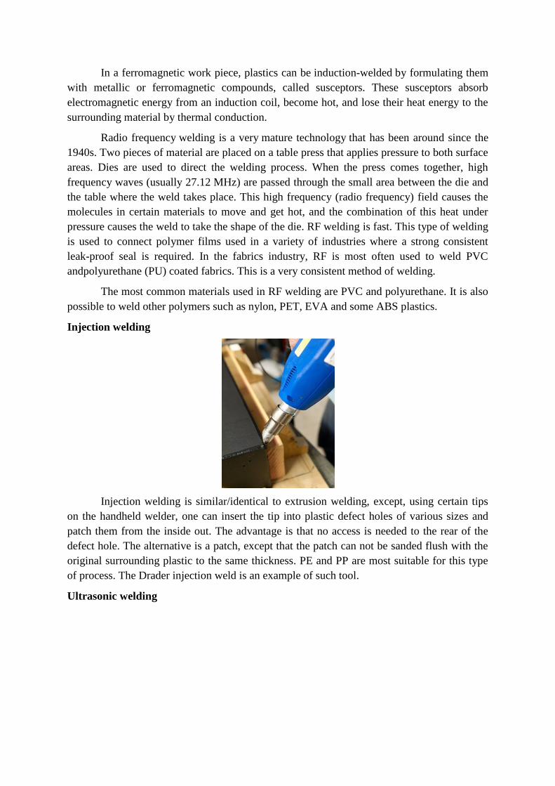
In a ferromagnetic work piece, plastics can be induction-welded by formulating them
with metallic or ferromagnetic compounds, called susceptors. These susceptors absorb
electromagnetic energy from an induction coil, become hot, and lose their heat energy to the
surrounding material by thermal conduction.
Radio frequency welding is a very mature technology that has been around since the
1940s. Two pieces of material are placed on a table press that applies pressure to both surface
areas. Dies are used to direct the welding process. When the press comes together, high
frequency waves (usually 27.12 MHz) are passed through the small area between the die and
the table where the weld takes place. This high frequency (radio frequency) field causes the
molecules in certain materials to move and get hot, and the combination of this heat under
pressure causes the weld to take the shape of the die. RF welding is fast. This type of welding
is used to connect polymer films used in a variety of industries where a strong consistent
leak-proof seal is required. In the fabrics industry, RF is most often used to weld PVC
andpolyurethane (PU) coated fabrics. This is a very consistent method of welding.
The most common materials used in RF welding are PVC and polyurethane. It is also
possible to weld other polymers such as nylon, PET, EVA and some ABS plastics.
Injection welding
Injection welding is similar/identical to extrusion welding, except, using certain tips
on the handheld welder, one can insert the tip into plastic defect holes of various sizes and
patch them from the inside out. The advantage is that no access is needed to the rear of the
defect hole. The alternative is a patch, except that the patch can not be sanded flush with the
original surrounding plastic to the same thickness. PE and PP are most suitable for this type
of process. The Drader injection weld is an example of such tool.
Ultrasonic welding
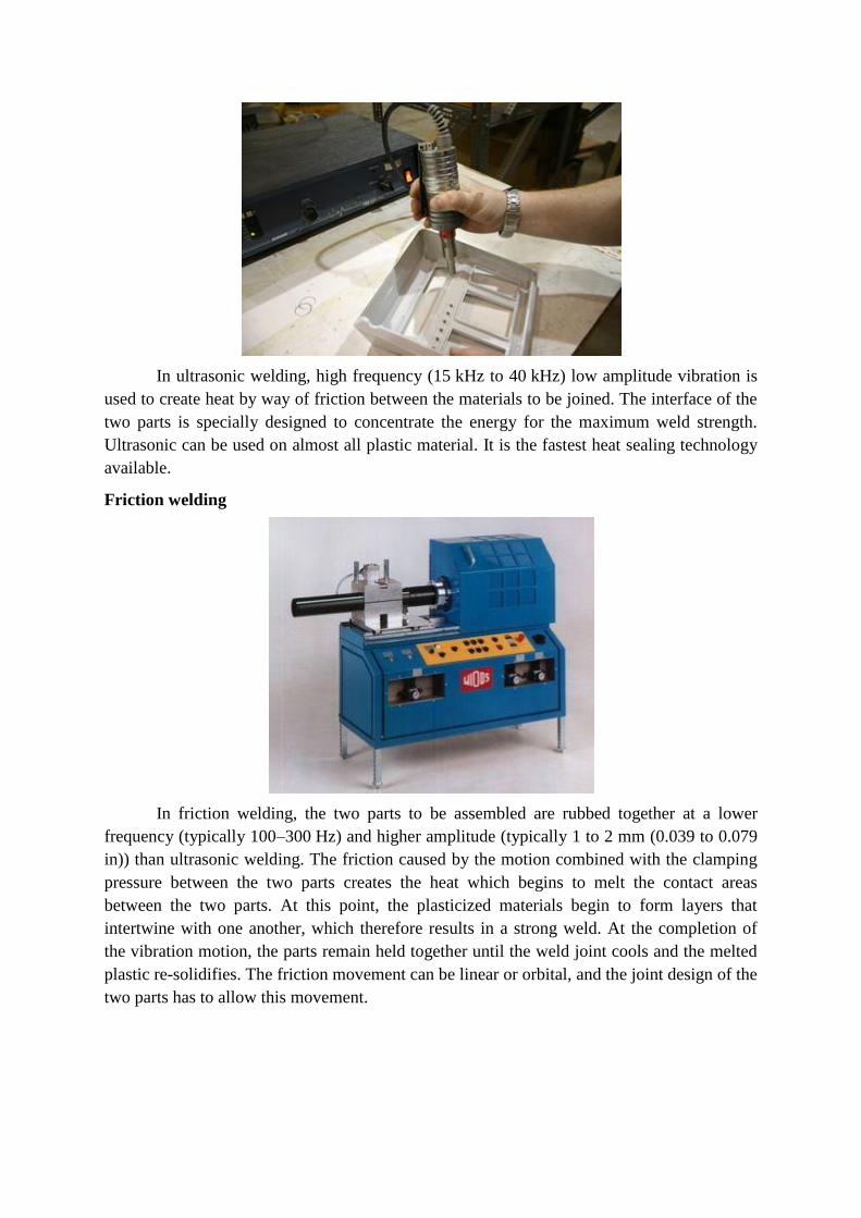
In ultrasonic welding, high frequency (15 kHz to 40 kHz) low amplitude vibration is
used to create heat by way of friction between the materials to be joined. The interface of the
two parts is specially designed to concentrate the energy for the maximum weld strength.
Ultrasonic can be used on almost all plastic material. It is the fastest heat sealing technology
available.
Friction welding
In friction welding, the two parts to be assembled are rubbed together at a lower
frequency (typically 100–300 Hz) and higher amplitude (typically 1 to 2 mm (0.039 to 0.079
in)) than ultrasonic welding. The friction caused by the motion combined with the clamping
pressure between the two parts creates the heat which begins to melt the contact areas
between the two parts. At this point, the plasticized materials begin to form layers that
intertwine with one another, which therefore results in a strong weld. At the completion of
the vibration motion, the parts remain held together until the weld joint cools and the melted
plastic re-solidifies. The friction movement can be linear or orbital, and the joint design of the
two parts has to allow this movement.
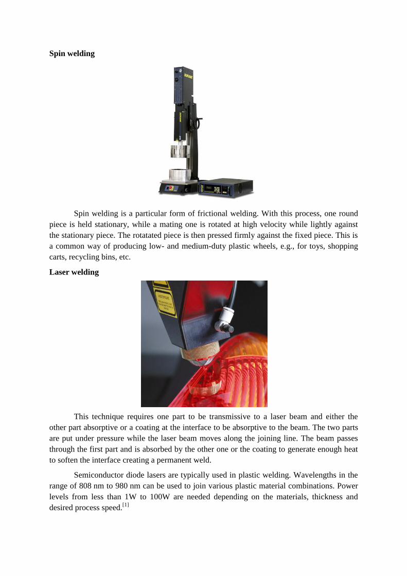
Spin welding
Spin welding is a particular form of frictional welding. With this process, one round
piece is held stationary, while a mating one is rotated at high velocity while lightly against
the stationary piece. The rotatated piece is then pressed firmly against the fixed piece. This is
a common way of producing low- and medium-duty plastic wheels, e.g., for toys, shopping
carts, recycling bins, etc.
Laser welding
This technique requires one part to be transmissive to a laser beam and either the
other part absorptive or a coating at the interface to be absorptive to the beam. The two parts
are put under pressure while the laser beam moves along the joining line. The beam passes
through the first part and is absorbed by the other one or the coating to generate enough heat
to soften the interface creating a permanent weld.
Semiconductor diode lasers are typically used in plastic welding. Wavelengths in the
range of 808 nm to 980 nm can be used to join various plastic material combinations. Power
levels from less than 1W to 100W are needed depending on the materials, thickness and
desired process speed.[1]
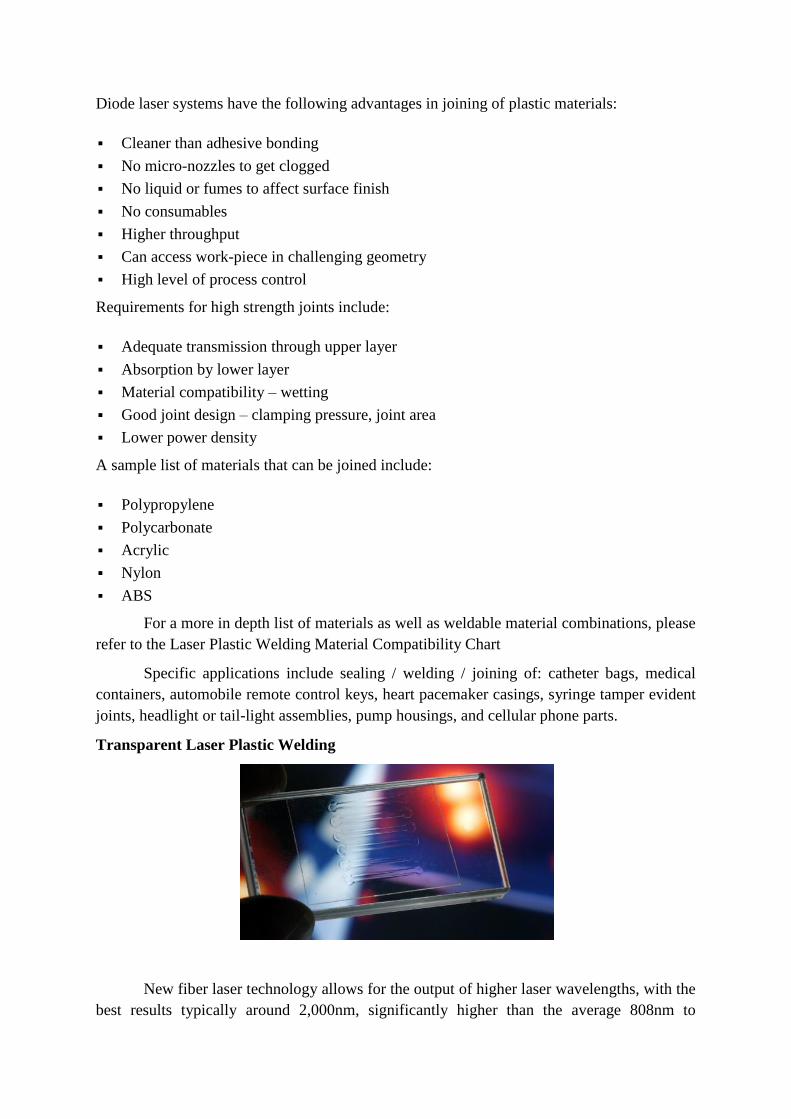
Diode laser systems have the following advantages in joining of plastic materials:
Cleaner than adhesive bonding
No micro-nozzles to get clogged
No liquid or fumes to affect surface finish
No consumables
Higher throughput
Can access work-piece in challenging geometry
High level of process control
Requirements for high strength joints include:
Adequate transmission through upper layer
Absorption by lower layer
Material compatibility – wetting
Good joint design – clamping pressure, joint area
Lower power density
A sample list of materials that can be joined include:
Polypropylene
Polycarbonate
Acrylic
Nylon
ABS
For a more in depth list of materials as well as weldable material combinations, please
refer to the Laser Plastic Welding Material Compatibility Chart
Specific applications include sealing / welding / joining of: catheter bags, medical
containers, automobile remote control keys, heart pacemaker casings, syringe tamper evident
joints, headlight or tail-light assemblies, pump housings, and cellular phone parts.
Transparent Laser Plastic Welding
New fiber laser technology allows for the output of higher laser wavelengths, with the
best results typically around 2,000nm, significantly higher than the average 808nm to
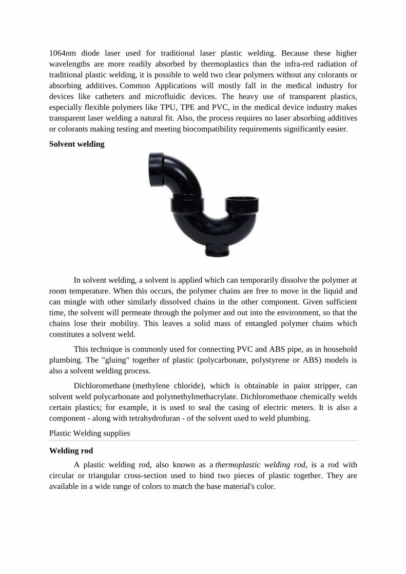
1064nm diode laser used for traditional laser plastic welding. Because these higher
wavelengths are more readily absorbed by thermoplastics than the infra-red radiation of
traditional plastic welding, it is possible to weld two clear polymers without any colorants or
absorbing additives. Common Applications will mostly fall in the medical industry for
devices like catheters and microfluidic devices. The heavy use of transparent plastics,
especially flexible polymers like TPU, TPE and PVC, in the medical device industry makes
transparent laser welding a natural fit. Also, the process requires no laser absorbing additives
or colorants making testing and meeting biocompatibility requirements significantly easier.
Solvent welding
In solvent welding, a solvent is applied which can temporarily dissolve the polymer at
room temperature. When this occurs, the polymer chains are free to move in the liquid and
can mingle with other similarly dissolved chains in the other component. Given sufficient
time, the solvent will permeate through the polymer and out into the environment, so that the
chains lose their mobility. This leaves a solid mass of entangled polymer chains which
constitutes a solvent weld.
This technique is commonly used for connecting PVC and ABS pipe, as in household
plumbing. The "gluing" together of plastic (polycarbonate, polystyrene or ABS) models is
also a solvent welding process.
Dichloromethane (methylene chloride), which is obtainable in paint stripper, can
solvent weld polycarbonate and polymethylmethacrylate. Dichloromethane chemically welds
certain plastics; for example, it is used to seal the casing of electric meters. It is also a
component - along with tetrahydrofuran - of the solvent used to weld plumbing.
Plastic Welding supplies
Welding rod
A plastic welding rod, also known as a thermoplastic welding rod, is a rod with
circular or triangular cross-section used to bind two pieces of plastic together. They are
available in a wide range of colors to match the base material's color.
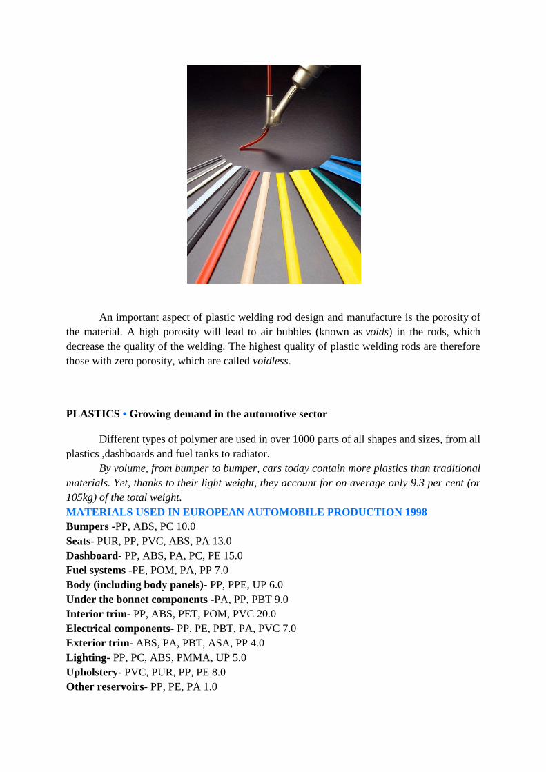
An important aspect of plastic welding rod design and manufacture is the porosity of
the material. A high porosity will lead to air bubbles (known as voids) in the rods, which
decrease the quality of the welding. The highest quality of plastic welding rods are therefore
those with zero porosity, which are called voidless.
OS
PLASTICS • Growing demand in the automotive sector
Different types of polymer are used in over 1000 parts of all shapes and sizes, from all
plastics ,dashboards and fuel tanks to radiator.
By volume, from bumper to bumper, cars today contain more plastics than traditional
materials. Yet, thanks to their light weight, they account for on average only 9.3 per cent (or
105kg) of the total weight.
MATERIALS USED IN EUROPEAN AUTOMOBILE PRODUCTION 1998
Bumpers -PP, ABS, PC 10.0
Seats- PUR, PP, PVC, ABS, PA 13.0
Dashboard- PP, ABS, PA, PC, PE 15.0
Fuel systems -PE, POM, PA, PP 7.0
Body (including body panels)- PP, PPE, UP 6.0
Under the bonnet components -PA, PP, PBT 9.0
Interior trim- PP, ABS, PET, POM, PVC 20.0
Electrical components- PP, PE, PBT, PA, PVC 7.0
Exterior trim- ABS, PA, PBT, ASA, PP 4.0
Lighting- PP, PC, ABS, PMMA, UP 5.0
Upholstery- PVC, PUR, PP, PE 8.0
Other reservoirs- PP, PE, PA 1.0
Plastics In Automotive Markets Today
Plastics encompass a wide variety of functional polymeric compounds that exhibit a
vast range of desirable properties. They are durable, strong and lightweight. They can be
made transparent, translucent or opaque; soft, flexible or hard in almost any shape, size or
color. They can be heat-, chemical- and corrosion resistant.
They are excellent thermal and electrical insulators and also can be made electrically
and thermally conductive. Because of plastics‘ versatility, they are extremely cost-effective in
a wide variety of commercial applications including a broad range of uses in the
transportation market. The use of both thermosets and thermoplastics in passenger vehicles
has grown from about 30 kilograms per vehicle in 1970 to about 150 kilograms today. A
midsize automobile manufactured in North America is about 10-12 percent plastics by
weight. The material volume is much higher. Because plastics are versatile and lightweight,
they make up approximately 50 percent of the material volume of new cars.
The Need for Fuel Efficiency and Reduction in Green House Gases
Leading experts say that the easiest and least expensive way to reduce the energy
consumption and emissions of a vehicle is to reduce the weight of the vehicle. To achieve
lightweight architectures, without compromising on rigidity, automakers have been
researching the replacement of steel with plastics, composites, foams, aluminum and
magnesium. The recycling and recovery of end-of-life vehicles, which involves recovery
targets of 85%, are driving the auto industry to adopt lightweight materials technology to
meet these recovery targets. Weight reduction also offers a potentially cost-effective means to
reduce fuel consumption and greenhouse gases from the transportation sector. It has been
estimated that for every 10% reduction in the weight of the total vehicle, fuel economy
improves by 5-7%. Thus for every kilogram of vehicle weight reduction, there is the potential
to reduce carbon dioxide emissions by 20 kg.
Common Themes and Top Priorities
At the Technology Integration Workshop, six important themes were repeatedly cited as
central to the challenge of enhancing future automotive safety using plastics.
1. Improve Characterization and Predictive Modeling of Plastics – Continuous improvement
in predictive modeling of the crash performance of plastic components is vital to
strengthening the position of plastics as a preferred automotive material. Automotive
designers also require extensive materials characterization data for new plastics as they
become available. Obtaining reliable, validated constitutive data may require a coordinated,
industry-wide effort.
2. Develop Material Classifications, Test Standards, and Performance Specifications – To
encourage design engineers and original equipment manufacturers (OEMs) to choose plastics
over competing materials, designers must be confident in the materials‘ ability to achieve
required performance in the application. Because plastics are less familiar than metals to most
design engineers, the plastics industry must benchmark performance and create material
classifications to characterize their products. Afterward, OEM material performance
specifications and test methods must be updated and expanded to reflect the unique properties
and capabilities of these new materials.
3. Enhance Crash Performance with Improved Energy Management – Managing the impact
energy created during a crash and protecting occupants from absorbing too much of this
energy is a fundamental part of vehicle safety. Advanced plastic components and systems in
the interior, body and exterior, and powertrain systems are sought to allow automakers to
manage crash energy in creative, more effective ways.
4. Uncover Plastic Opportunities under Evolving Active and Passive Safety Standards and
Light weighting Regulations – Understanding technology needs for meeting evolving safety
standards and light weighting regulations addressing both crash worthiness and crash
avoidance is a necessary foundation for planning future plastics research. The industry must
better define plastics performance requirements of new safety standards and use with new
integrated components, alternative fuel vehicles, powertrain options, and transportation
infrastructure. Once these issues are determined, new opportunities for optimizing safety and
light weighting with plastics should be identified.
5. Accommodate Changing Demographics to Older Population – As the population of older
drivers increases, improved counter measures and crash performance systems will be needed
to keep these passengers safe. Many older drivers have lower biomechanical tolerances and
require special safety features to avoid injury. With targeted research, highly versatile plastics
may enable important advances in safety features that are needed to protect the 65-and-older
population.
6. Make Automotive Safety with Plastics Affordable – Optimizing material selection for
automotive safety components will require that plastics become more affordable, both as a
material and as they enable efficiency gains throughout the vehicle manufacturing and
assembly process. At the same time, the perception among automotive customers must be
changed to appreciate the value of safety features enabled by plastics to increase their
willingness to select those features.
Plain steel
PLASTICS • Drivers for the 21st century
Thanks to plastics, the cars we dream of today are quickly being developed – offering
high performance, cleaner driving and advanced safety and convenience features.
As we enter an era of mass customisation, where products will increasingly be
tailored to meet individual requirements, diversity will become the new rule. Cars will come
in all shapes and sizes, metamorphosing into new ‗part-carpart- truck‘ combinations. Plastics‘
versatility and flexibility will support the trend in the automotive industry to build very
different cars based on the same chassis and a core set of components, thus reducing research
and development time and the retail price. Plastics-based composite materials will
substantially reduce the weight of the future car and, as a result, less energy will be required
to propel it. In fact, the 100kg of plastics that have been added to the average car have already
displaced 200 to 300kg of other materials. Thanks to lightweight plastics, driving 50
kilometres on one litre of fuel will soon be possible and the commercialisation of electric cars
that need just 40kW instead of the 120kW a conventional-size vehicle requires today, could
be only a few years away.
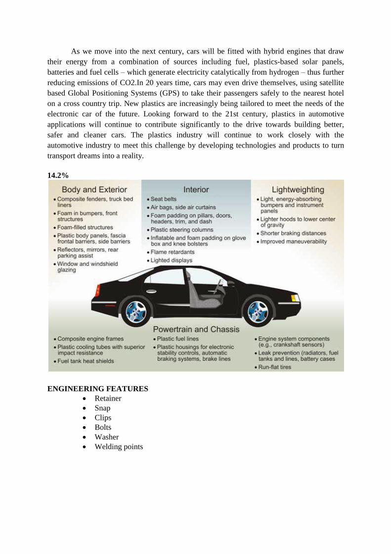
As we move into the next century, cars will be fitted with hybrid engines that draw
their energy from a combination of sources including fuel, plastics-based solar panels,
batteries and fuel cells – which generate electricity catalytically from hydrogen – thus further
reducing emissions of CO2.In 20 years time, cars may even drive themselves, using satellite
based Global Positioning Systems (GPS) to take their passengers safely to the nearest hotel
on a cross country trip. New plastics are increasingly being tailored to meet the needs of the
electronic car of the future. Looking forward to the 21st century, plastics in automotive
applications will continue to contribute significantly to the drive towards building better,
safer and cleaner cars. The plastics industry will continue to work closely with the
automotive industry to meet this challenge by developing technologies and products to turn
transport dreams into a reality.
14.2%DEFECTS MANUAL
ENGINEERING FEATURES
Retainer
Snap
Clips
Bolts
Washer
Welding points

Steel vs. Plastics: The Competition for Light-Vehicle Fuel Tanks
As weight and cost savings drive changes in performance criteria for automotive materials,
original equipment manufacturers (OEMs) are taking a harder look at the historically terne-
coated steel used for gas tanks. This article compares steel and plastic for gas tank uses
according to performance attributes and a competitive analysis. Legislation issues and
current OEM activity are included.
INTRODUCTION
Historically, terne-coated steel (an 8% tin-lead coating) has been the mainstay for
automotive gas tanks; however, several issues are changing the performance criteria that must
be met and, thus, threaten the application of steel products. The drivers for a material change
are legislation, increased required part life to ten years/241,350 kilometers, permeability,
weight, packaging, safety, and cost. In this article, the performance attributes of the plastic
and steel alternatives are reviewed from an original equipment manufacturer (OEM)
perspective in the critical areas of manufacturability, cost, design, weight, safety, corrosion,
and recyclability.
A comparative analysis of the various plastic and steel alternatives indicates that steel
remains a cost-effective material that meets all of the required performance criteria. A more
specific cost comparison of the new plastic tanks (i.e., multilayer or barrier coated) with the
new steel tanks is still required. Many of the drivers such as lead reduction, clean fuels,
permeability, and weight are a direct result of legislative and regulatory pressures
PLASTIC FUEL TANKS
Since the mid-1980s, automakers have been displacing coated-steel fuel tanks with
plastic ones. During the 1993 model year, approximately 2.7-3 million cars and trucks built in
North America used nonmetallic tanks. This represents 22-25% of the market, compared to
16% in 1990. By comparison, the European market uses 70-90% plastic tanks, and the
Japanese market uses 5% plastic tanks4 (Figure 1).
Although plastic-tank applications have experienced some reversals as a result of the
stricter permeation standards, some experts believe their usage will gain momentum by the
end of the decade as new plastics technology is converted to commercially feasible
operations. The Delphi VII report by theUniversity of Michigan indicates that experts predict
plastic tanks will capture 28% of the North American market by the end of 1996 and up to
50% of the market by 2000.5 However, this projection needs to be tempered with the higher
manufacturing cost and recyclability issues of the multilayer plastic tanks that will be
required to meet the stricter permeation standards.
This projection is considered as the worst-case scenario for steel if the industry fails to
provide the OEMs with a cost-effective steel alternative that meets all of the performance
criteria. Table I indicates the production volume of vehicles built in North America;6 Table II
shows the estimated number of plastic gas tank units (according to Delphi VII projections)
and their impact on steel shipments.
As of 1993, the steel industry lost the opportunity to ship about 34,473 tonnes of steel
as a result of plastics gains in gas-tank applications. In the worst-case scenario, continued
acceptance of plastic gas tanks will increase steel's loss to 71,667 tonnes in 2000—an
additional 43,544 tonnes. This means that annual shipment of 125,191 tonnes of steel will be
reduced by better than a third to a total of about 81,646 tonnes per year.
PLASTICS TECHNOLOGY
High-density polyethylene (HDPE) has been the resin of choice for plastic gas tanks,
and production capacity has been on the increase. Kautex of Canada built a new plant in
Avilla, Indiana, to meet anticipated increases in demand for plastic automotive fuel tanks.
Production was scheduled for 400,000 tanks in 1994 and eventually will be boosted to
between 600,000 and 700,000 units per year.7 These plastic tanks are currently being used
on Chrysler's Jeep Cherokee and T300 trucks.
Belgium-based Solvay is the exclusive supplier of plastic fuel tanks to General
Motors' Saturn Division. Solvay has also expanded their Canadian subsidiary in Blenheim,
Ontario, and installed two new blow-molding machines to make HDPE tanks for
the Chrysler's LH series and Viper sports car. Chrysler expects to sell 300,000 LH vehicles,
all with HDPE tanks that offer more volume capacity than steel tanks. Monolayer-HDPE
tanks offer long-term structural integrity but will not meet future permeation
requirements. Chrysler started to switch in 1995 to multilayered HDPE to meet the more
stringent SHED test.

The emergence of new technologies has enabled the increase of plastic gas tanks.
These new technologies can be grouped into either multilayer or barrier types.
Multilayer Technology
Some manufacturers see multilayer tank technology as the answer to stricter emission
standards. Ford uses six-layer fuel tanks made of HDPE and, at one point, considered a $110
million investment in machinery and equipment to produce the tanks (which would have been
the first commercial use of coextruded tanks). However, Ford decided to increase steel-tank
stamping capacity at Dearborn; the Explorer and the new F-150 truck(PN96) gas tanks have
been switched back from plastic to zinc-nickel coated steel.
Kautex is supplying Ford's facility in Milan, Michigan, with this six-layer technology.
The tanks are designed to meet California's stricter evaporative fuel standards and consist of
an inner layer of HDPE joined by an adhesive layer and barrier layer of polyamide or
ethylene-vinyl alcohol copolymer. An additional adhesive layer is joined by a layer of
"regrind" and an outer layer of HDPE.
Walbro Automotive Corporation began commercial production of multilayer plastic
fuel tanks for 1995 models. Annual production of these multilayer tanks is expected to reach
500,000 units by 1998. Their tank uses a barrier layer of ethylene-vinyl alcohol (EVOH) that
is sandwiched between two layers of HDPE.
Barrier Technology
Air Products and Chemicals of Allentown, Pennsylvania, has commercialized a
fluorine-based barrier technology that enables plastic fuel tank manufacturers to meet more
stringent emissions standards. The SHED tests completed in 1992 on Airoguard plastic tanks
produced by Kautex of Canada indicated hydrocarbon permeation rates as low as 0.1 g/24
h—significantly lower than rates for tanks using previously available barrier technology. The
performance of the Airoguard tanks compares with multilayer extrusion tanks while
maintaining the long-term structural integrity of monolayer tanks.10
Solvay Automotive of Troy, Michigan, has developed technology to keep HDPE tank
emissions down to 0.2 g/24 h or less, even with methanol-containing fuels.11
Using
technology called Solvay-optimized fluorination, Solvay equals or exceeds the permeation
performance of coextrusion with EVOH barrier resin. Solvay continues to add multilayer
capacity to meet Chrysler's requirements.
Aero Tec Laboratories of Ramsey, New Jersey, has developed a semiflexible safety
fuel tank made from an undisclosed olefin compound of polymers and antidiffusion-barrier
additives.12
The tank can be used for race cars and military vehicles as well as general
automotive aftermarkets.
STEEL FUEL TANKS
North American auto manufacturers are currently supplied with tanks comprising a steel
substrate coated with either terne or zinc-nickel. In all, about 125,191 tonnes of steel
substrate per year are applied to gas tanks.Stainless steel tanks have been tested, and although
effective in flexible fuels, they are difficult to form without severe breakage occurring during
stamping. Also, stainless steel is expensive, with an estimated cost ratio to terne steel
exceeding 5:1.The electrocoated zinc-nickel product is painted on both sides with an
aluminum-rich epoxy. Industry accelerated tests on the corrosion of painted zinc-nickel
confirm that it will meet a ten-year life in current fuels and flex-fuels and resist external
corrosion.Testing the characteristics of painted galvanneal (zinc-iron alloy coated steel) have
found it effective for resisting corrosion on both the inside and outside surfaces of the
tank. General Motors has a product undergoing testing.
Hot-dipped tin has also been found to be effective for resisting all fuels, but it does
require a paint coating for exterior protection from road-induced corrosion. This product
welds faster than painted terne and has a better potential for good solderability than painted
galvanneal and zinc-nickel coated steel substrates, permitting the attachment of fuel filler
tubes and other lines.
PERFORMANCE ATTRIBUTES: PLASTIC VERSUS STEEL
Manufacturability
Terne plate holds a materials cost advantage over HDPE: $0.66-0.79/kg vs. $0.86-
1.08/kg.13
The cost of the material is not the only driver; consideration includes the net cost
of the fabricated tank and its reliability within the total fuel system of the vehicle, including
the tank, filler tube, level control, baffles, the housing reservoir for the sending unit, and other
assorted tubing, fittings, and seals from the tank to the engine. All of these components must
function properly with the various fuel types and for the life of the car. Unforeseen corrosion
can easily contaminate the fuel delivery system and cause costly repairs.
Manufacturing costs for either tank material seem conflicting, depending on the
source. Nevertheless, due to the invested capital of OEMs on stamping, welding, and
assembly equipment for metal tanks, their cost structure indicates a lower cost per piece on
steel tanks versus plastic ones, with the latter usually being outsourced (except for
some Ford models).
Plastic tanks are formed by blowing a thick continuous tube of HDPE within a mold
that determines the final shape of the virtually seamless part, which could include the filler
neck. The blowing molds are cast from aluminum and cost considerably less than machined
steel dies used to stamp steel tanks. In general, four or more molds are integrated into one
rotary style blow-molding machine to achieve the desired productivity (i.e., one station blows
while the other one cools). Typically, the OEMs outsource the plastic tanks to various
suppliers who bid for the business. The plastic tank manufacturer also has to either chlorinate
or fluorinate the plastic to retard permeation, and both processes can be highly toxic if

mishandled. This represents additional OSHA requirements, which add to the cost of the
tank.
Design Features and Weight
Plastic tanks have the ability to meet packaging constraints with complex shapes, and
design engineers have greater flexibility in the car design and styling without having to worry
about fitting the gas tank. The plastic tank could virtually be made to fit whatever cavities are
left by the design. Other attachments to and within the plastic tank require gasketed
mechanical joints. However, plastic swells with constant exposure to organic liquids and
vapor, thus making the joints very critical in the event of repairing the tank hardware.
The average gas tank for a compact automobile (e.g., Nissan Altima) can boast weight
savings of up to 30% versus a similar steel tank.14
However, Cadillac claims that although
their plastic tanks allow design flexibility with increased safety, they do not achieve any
weight savings over steel tanks.15
These two examples seem to contradict the general view
that plastic's weight advantage increases with the size of the tank. On the other hand, the new
permeability requirement is expected to diminish the weight advantage of plastics.
Safety
One critical part of the performance criteria of the tank is its ability to meet crash
requirements. Generally, plastic tanks are considered safer in crashes because they are
seamless and, thus, not prone to failures in the vulnerable seam areas. They are not a source
of sparks. Also, plastic tanks deform and have some ability to rebound back to shape. When
steel tanks absorb energy and deform, the pressure within the tank increases as the volume
decreases. This makes them vulnerable at welded or clamped areas where failure can
potentially occur.
The thermal properties of the chosen material are also an issue, especially due to the
proliferation of injector fuel delivery systems, where a portion of the unused fuel delivered by
the gas pump is returned to the gas tank at "engine-hot" temperatures. At the same time, the
tank must withstand extreme temperatures in North America from -40°C to 79°C in-tank
temperatures. The 79°C temperature not only exceeds the boiling point of the alcohol fuels,
but also creates sagging problems for plastic (especially under the weight of a filled tank)
while the extreme cold introduces potential cracking problems. As a result, OEMs resort to
heavier gauge plastic, negating at least some of the weight advantage, and must also use
support brackets and special shields against the heat of local sources like an inferior or
perforated muffler or tailpipe. High ambient temperatures underneath the car remain a
consideration.
Plastic acts as an insulator to retard heat transfer to the fuel when compared to a steel
tank. In the case of an under-car fire, plastic tanks will retard the rise in fuel temperature, but
they will soften, sag, and eventually release the fuel. A steel tank does not sag in a fire;
however, the fuel temperature may rise rapidly, perhaps resulting in over pressurization and
release of fuel through a mechanical fitting. The American Iron and Steel
Institutereports16
that a series of more than 75 tests undertaken by the National Fire
Prevention Research Foundation and Factory Mutual Research Corporation indicated that
plastic containers storing flammable or combustible liquids in general purpose warehouses
fail abruptly when exposed to a small fire. This failure results in a rapidly developing spill
fire that overpowers conventional sprinkler systems. The same tests conducted with
flammable and combustible liquids stored in steel containers resulted in no spill fire, no
excessive temperatures, no content involvement, and no significant loss of visibility due to
smoke. The fires involving the steel containers extinguished themselves. These findings have
led to a return to steel containers from plastics for safety and fire insurance cost reasons. It is
not known if tests have been conducted by OEMs to compare the performance of steel and
plastic tanks in under-car fire situations.
Corrosion
Corrosion is a well-known concern on both the inside and outside surfaces of tanks.
The outside surfaces and supporting structure are exposed to road chemicals, salt, mud, and
gravel. The corrosion issue is critical with zinc-coated products that replace terne plate
because of their sacrificial nature, which puts an even higher demand on the quality of the
barrier film for both inside and outside surfaces. In contrast, the HDPE gas tanks are inert to
the corrosive environments inside and outside the tank.
Recyclability
The Resource Conservation and Recovery Act discourages the use of materials that
cannot be recycled and might end up in landfills.17
As a result, automotive-design engineers
must not only meet customer, design, styling, cost, weight, and regulatory needs but also
environmental criteria. All materials suppliers must show that their product is not only lighter
and cost effective but also recyclable. In this respect, plastics must work the hardest to show
that they are recyclable and have the ability to be recovered in vehicle disassembly in a cost-
effective manner. To accomplish these objectives, automotive designers must develop
prototypes that can be disassembled easily into the various material groups that have a
recycling infrastructure.
Despite progress in recycling, the proliferation of plastics in automotive applications faces
some hurdles.
The absence of a plastics recycling infrastructure. The infrastructure for recovering
and recycling the ferrous content of cars is well established—70-80% of a typical
passenger car is recoverable steel and iron.
The molding process for plastic fuel tanks. As is the case for other ap-plications, this
process results in roughly 30% of plastic material ending as industrial waste.18
The necessary sorting of the various plastics types since mixing types can ruin the
batch. This is not a problem with steel—the scrap industry recycles 10.8 million
tonnes per year of shredded automotive iron and steel, which is used to make new
steel products.19
The lack of technology that dismantlers can use to quickly collect various plastics.
The current infrastructure of automobile dismantlers, shredders, and scrap-metal
processors is steel dominated and relies on magnetic separation and inexpensive
shredding equipment for efficient and low-cost processing. In the case of terne gas
tanks, the units are removed from the car, flattened, baled, and sent either to special
operators that can reclaim the lead or to the steel mill.
Cost. Recycled plastics are not cost competitive with virgin plastics.
While the recycling of HDPE gas tanks is easier to tackle in terms of dismantling and
avoiding type mixing, these tanks will not meet the new evaporative emissions standards. The
barrier-type and multilayer tanks that will meet such standards can pose a bigger challenge to
recycle in a cost-effective manner.

Table 1.1 Abbreviations
Symbol Plastic or composite
ABS
Acrylonitrile butadiene styrene copolymer
APK
Aliphatic polyketone
ASA
Acrylonitrile styrene acrylate copolymer
BMC
Bulk moulding compound
BMI
Bismaleimide
DMC
Dough moulding compound
EP
Epoxide (epoxy)
EPP
Expanded polypropylene
EPS
Expanded polystyrene
ETFE
Tetrafluoroethylene copolymer
EVOH
Ethylene vinyl alcohol
GFR
G lass fibre reinforced
GMT
G lass mat thermoplastic
HCPP
Highly crystalline polypropylene
HDPE
High density polyethylene
HIPS
High impact polystyrene
LCP
Liquid crystal polyester or liquid crystal polymer
MF
Melamine formaldehyde resin
MPF
Melamine phenol formaldehyde moulding compound
PA
Polyamide (nylon)
PA-GF
Glass fibre reinforced polyamide
PAEK
Polyarylether ketone
PAl
Polyamide-imide
PAA
Polyarylamide
PAS
Polyarylsulphone
PAT
P olya rylterep htha late (polyarylate)
PBT
Polybutylene terephthalate
PC
Polycarbonate
PCTFE
P olyc hi orotri flu orethyle ne
PDAP
Poly (diallyl phthalate)
PE
Polyethylene
PEK
Polyetherketone
PEEK
Polyetheretherketone
PEI
Polyetherimide
PEN
Polyethylene naphthalate
PEOX
Poly (ethylene oxide)
PES
Polyether sulphone
PET
Polyethylene terephthalate
PF
Phenol formaldehyde (phenolic)
PI
Polyimide
PMMA
Poly (methyl methacrylate) (acrylic)
PMMI
Poly (methyl methacrylate imide)
PMP
Poly (methylpentene)
POM
Polyoxymethylene
PP
Polypropylene
PPA
Polyphthalamide Vinyl ester resin
PP-E
Expanded polypropylene
PPF
Polyphenylene ether
PPO
Polyphenylene oxide (=PPE)
PPS
Polyphenylene sulphide
PS
Polystyrene
PSU
Polysulphone
PTFE
P olyeth ra fl uo roet hyle ne
PU
Polyurethane
PUR
Polyurethane
PVB
Polyvinyl butyrate
PVC
Polyvinyl chloride
PVDC
Polyvinylidene chloride
PVDF
Polyvinylidene fluoride
PVF
Polyvinyl fluoride
R-RIM PUR
Reinforced reaction injected moulded polyurethane
SAN SMA
Styrene acrylonitrile copolymer
SMC
Styrene maleic anhydride
S-RIM PUR
Sheet moulding compound
TPE-A
Structural reaction injection moulded polyurethane
TPE-E
Thermoplastic polyamide elastomer
TPE-O
Thermoplastic polyester elastomer
TPE-U
Thermoplastic polyolefin elastomer
UF
Thermoplastic polyurethane
UP
Urea formaldehyde
VP Unsaturated polyester resin