Embed Size (px)
DESCRIPTION
Plastic Composites - Forming & Shaping
Citation preview
Plastics & Composite Materials: Forming & Shaping
Text Reference: “Manufacturing Engineering and Technology”Text Reference: Manufacturing Engineering and Technology , Kalpakjian & Schmid, 6/e, 2010
Chapter 19
Plastics• Can be molded, cast, formed, machined
– In a few operationsIn a few operations– Easily
Rapidly– Rapidly• Can be joined• Can be coated• Can be shaped into discrete products • Can be produced as materials (sheets,
plates, rods, and tubing) for later p ates, ods, a d tub g) o atemanufacture into discrete parts
Some Plastics Terminologygy• Thermoplastic (TP) – Polymers that can be shaped
when heated and regain original hardness & strength upon coolingupon cooling– Have a linear or branched structure (weak secondary
bonds)Process is reversible– Process is reversible
– Acrylics, cellulosics, nylons, polyethylenes, polyvinyl chloride
Th t (TS) P l th t b• Thermoset (TS) – Polymers that become permanently set when heated– Have a cross-linked structure (strong secondary bonds) ( g y )– Process is irreversible– Epoxy, polyester, urethane, phenolics, silicones
• Elastomer (Rubber) Elastic; low elastic modulus• Elastomer (Rubber) – Elastic; low elastic modulus– Tires, footwear, gaskets, flooring, weatherstripping, hoses
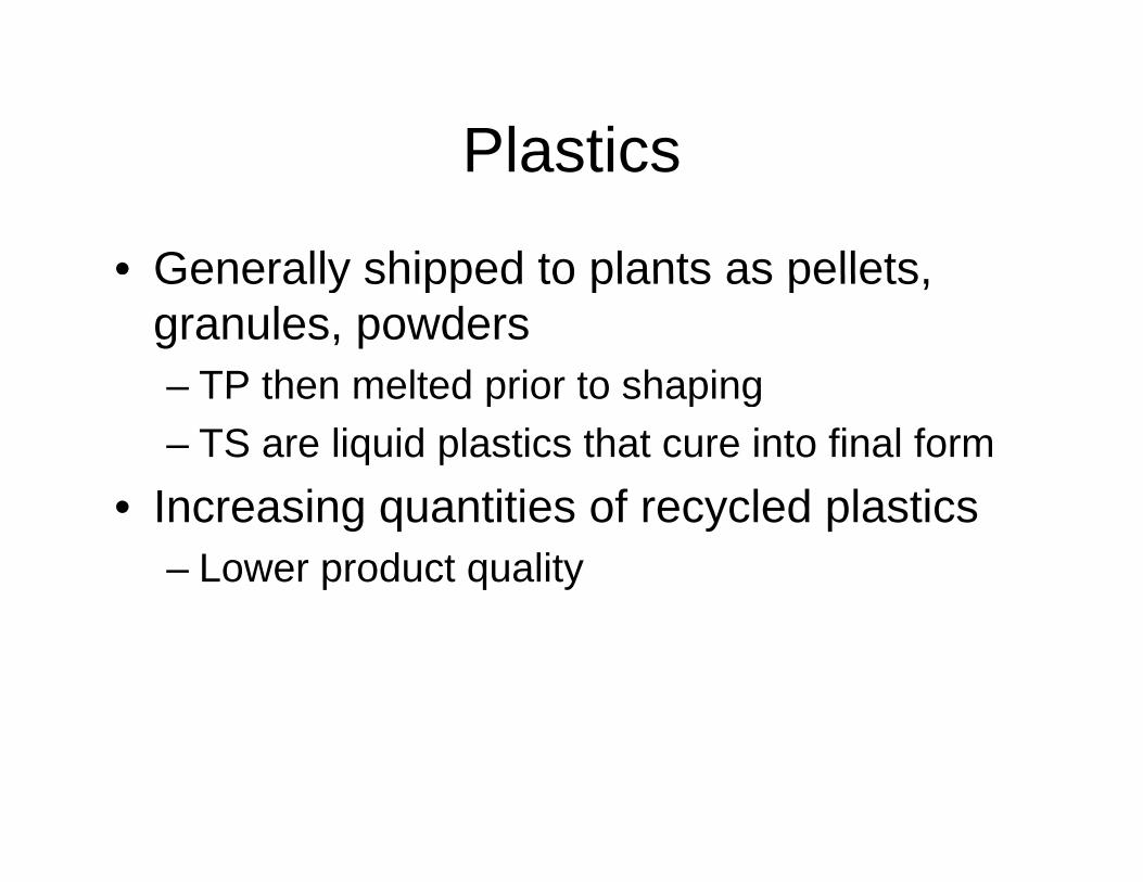
PlasticsPlastics
• Generally shipped to plants as pelletsGenerally shipped to plants as pellets, granules, powders
TP then melted prior to shaping– TP then melted prior to shaping– TS are liquid plastics that cure into final form
I i titi f l d l ti• Increasing quantities of recycled plastics– Lower product quality
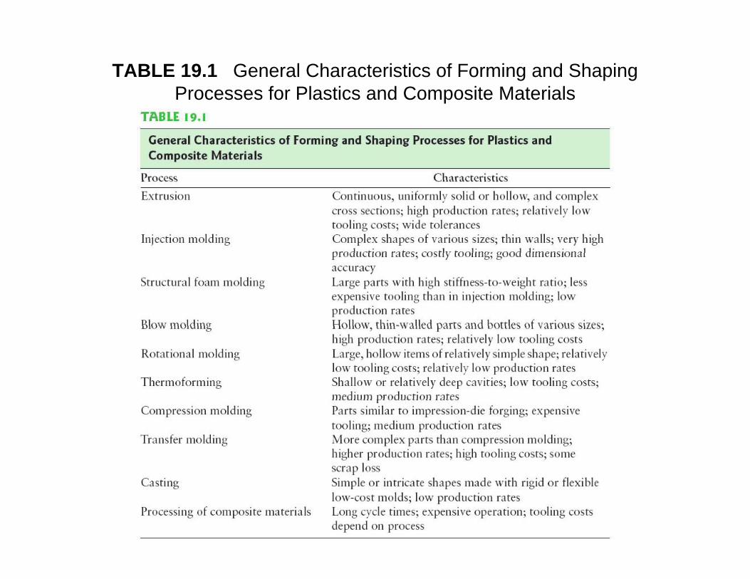
TABLE 19.1 General Characteristics of Forming and Shaping Processes for Plastics and Composite Materials
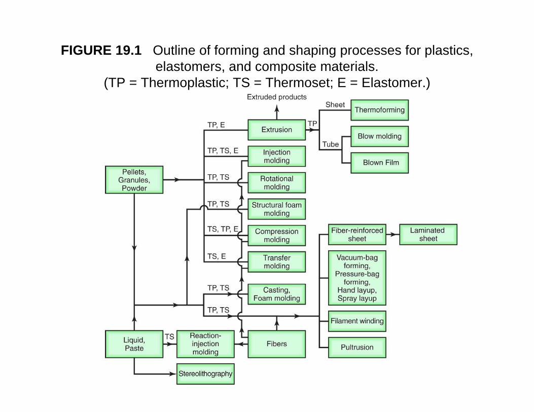
FIGURE 19.1 Outline of forming and shaping processes for plastics, elastomers, and composite materials.
(TP = Thermoplastic; TS = Thermoset; E = Elastomer.)
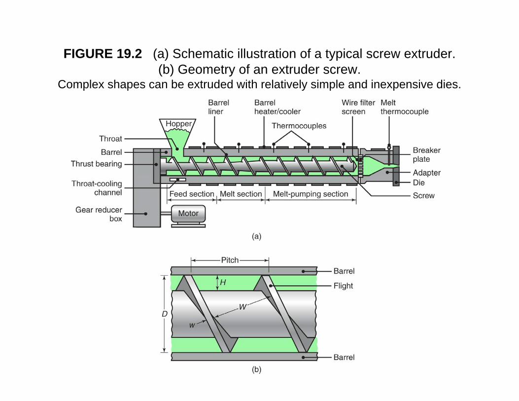
FIGURE 19.2 (a) Schematic illustration of a typical screw extruder. (b) Geometry of an extruder screw. ( ) y
Complex shapes can be extruded with relatively simple and inexpensive dies.
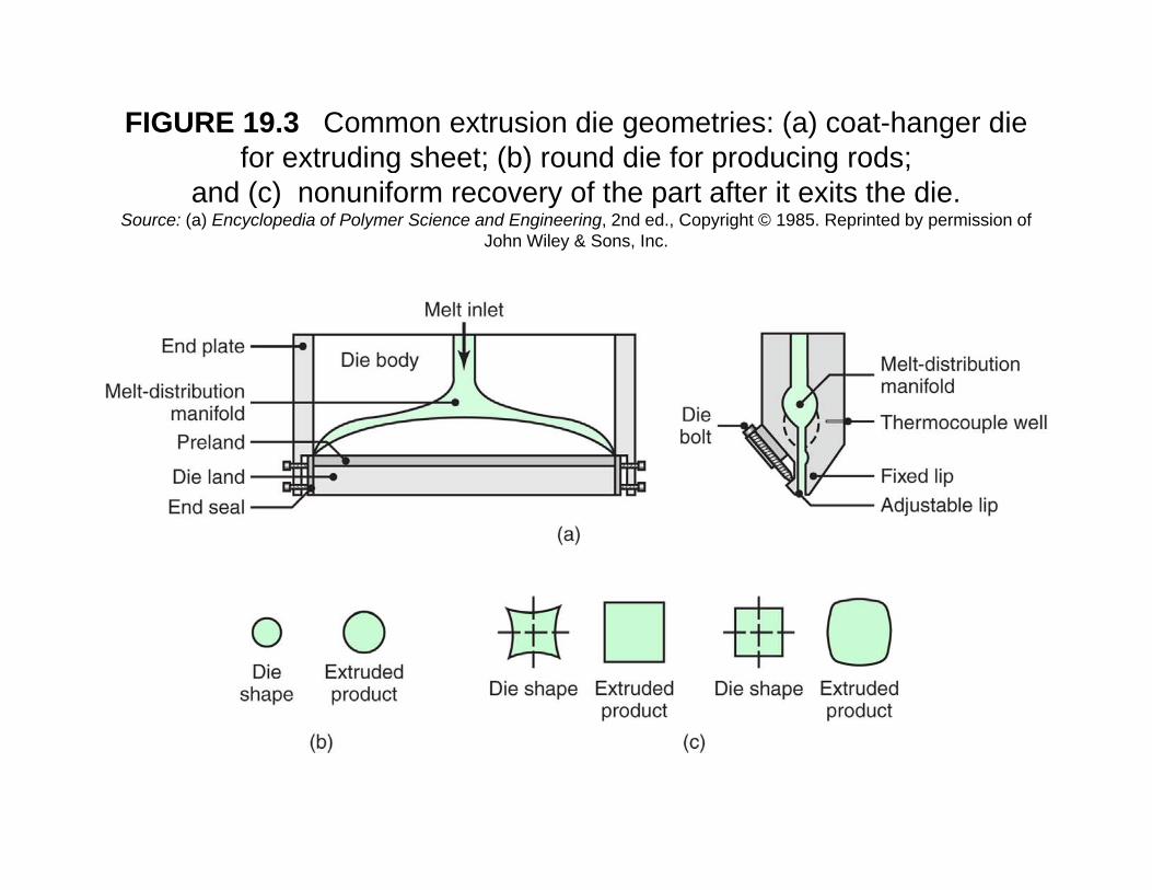
FIGURE 19.3 Common extrusion die geometries: (a) coat-hanger die for extruding sheet; (b) round die for producing rods;for extruding sheet; (b) round die for producing rods;
and (c) nonuniform recovery of the part after it exits the die. Source: (a) Encyclopedia of Polymer Science and Engineering, 2nd ed., Copyright © 1985. Reprinted by permission of
John Wiley & Sons, Inc.
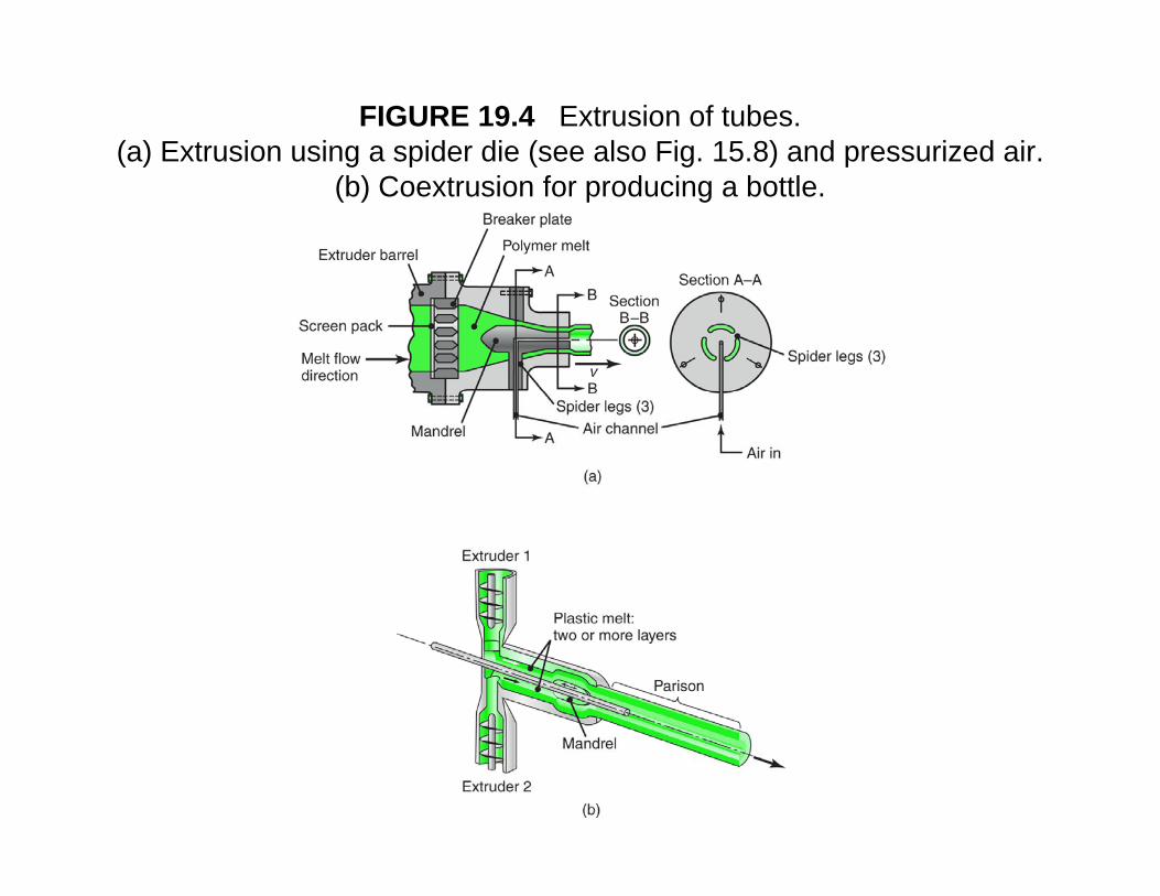
FIGURE 19.4 Extrusion of tubes. (a) Extrusion using a spider die (see also Fig. 15.8) and pressurized air. ( ) g p ( g ) p
(b) Coextrusion for producing a bottle.
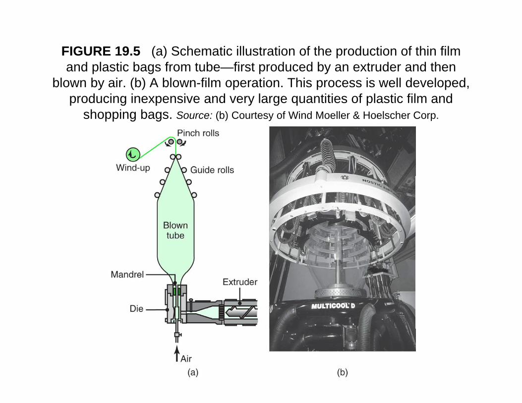
FIGURE 19.5 (a) Schematic illustration of the production of thin film and plastic bags from tube—first produced by an extruder and then
blown by air. (b) A blown-film operation. This process is well developed, producing inexpensive and very large quantities of plastic film and
shopping bags. Source: (b) Courtesy of Wind Moeller & Hoelscher Corp.
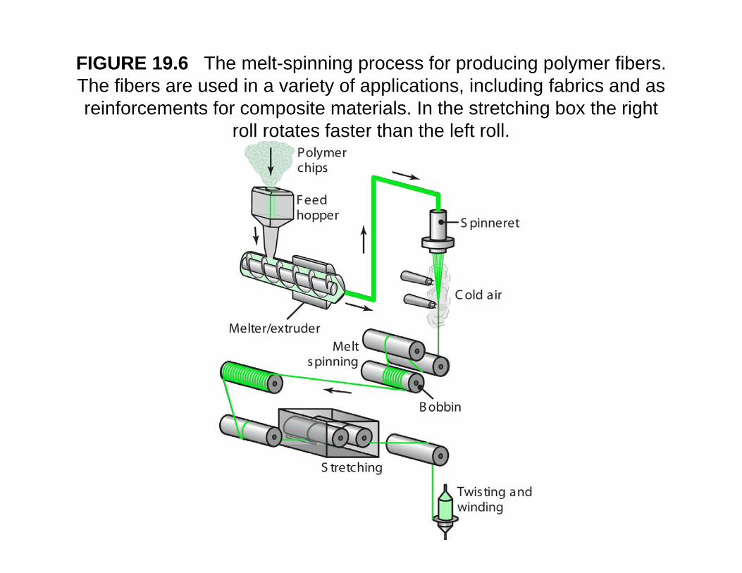
FIGURE 19.6 The melt-spinning process for producing polymer fibers. The fibers are used in a variety of applications, including fabrics and as reinforcements for composite materials In the stretching box the rightreinforcements for composite materials. In the stretching box the right
roll rotates faster than the left roll.
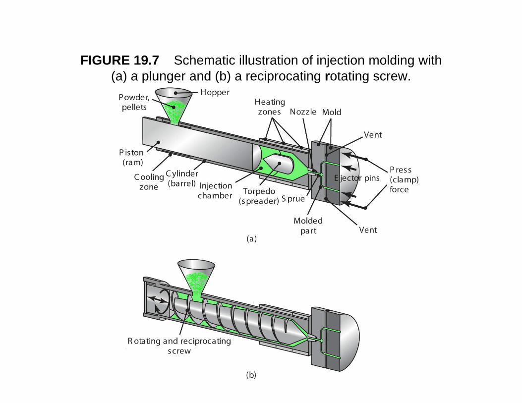
FIGURE 19.7 Schematic illustration of injection molding with (a) a plunger and (b) a reciprocating rotating screw(a) a plunger and (b) a reciprocating rotating screw.
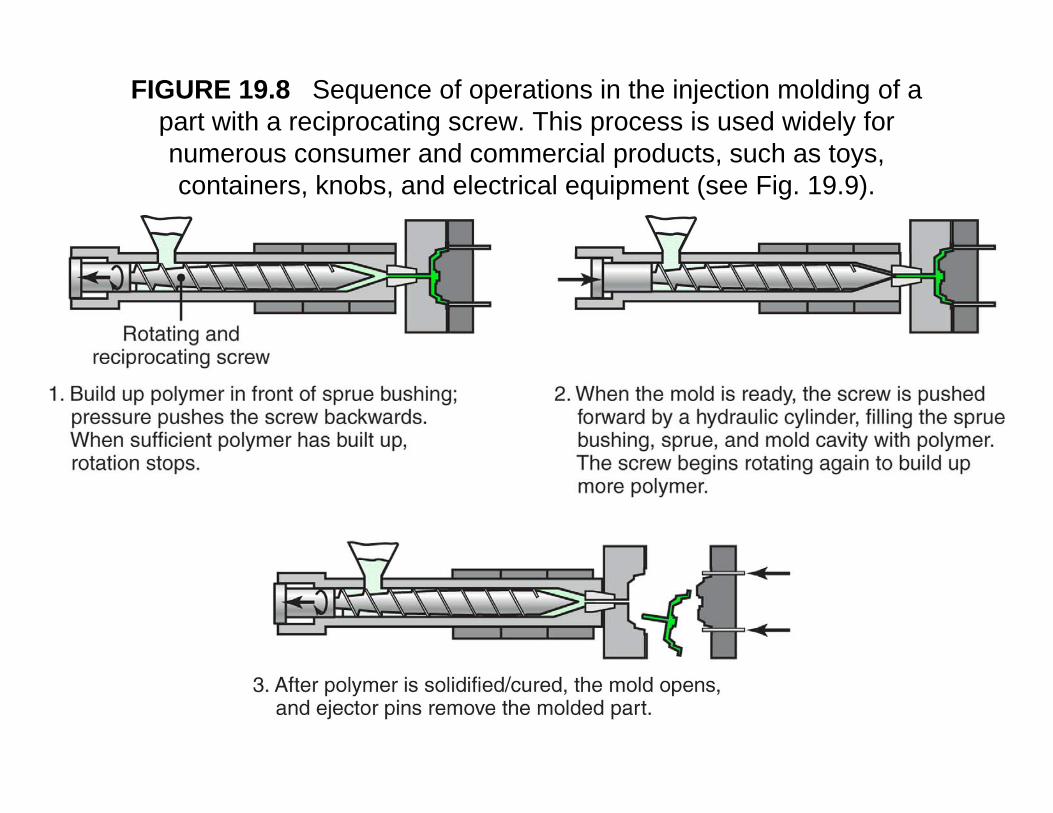
FIGURE 19.8 Sequence of operations in the injection molding of a part with a reciprocating screw. This process is used widely for numerous consumer and commercial products such as toysnumerous consumer and commercial products, such as toys, containers, knobs, and electrical equipment (see Fig. 19.9).
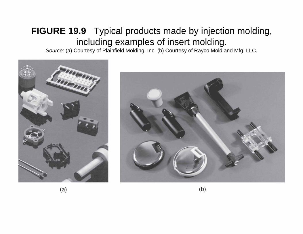
FIGURE 19.9 Typical products made by injection molding, including examples of insert moldingincluding examples of insert molding.
Source: (a) Courtesy of Plainfield Molding, Inc. (b) Courtesy of Rayco Mold and Mfg. LLC.
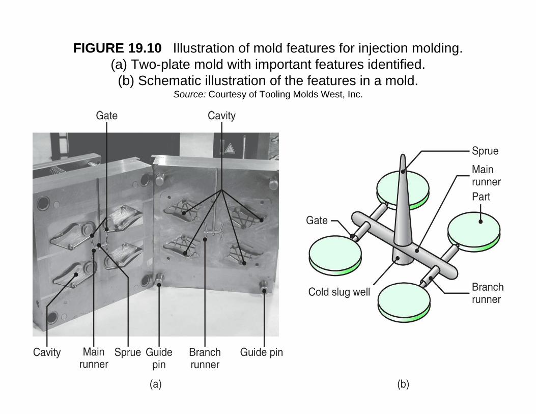
FIGURE 19.10 Illustration of mold features for injection molding. (a) Two-plate mold with important features identified. (b) S h ti ill t ti f th f t i ld(b) Schematic illustration of the features in a mold.
Source: Courtesy of Tooling Molds West, Inc.
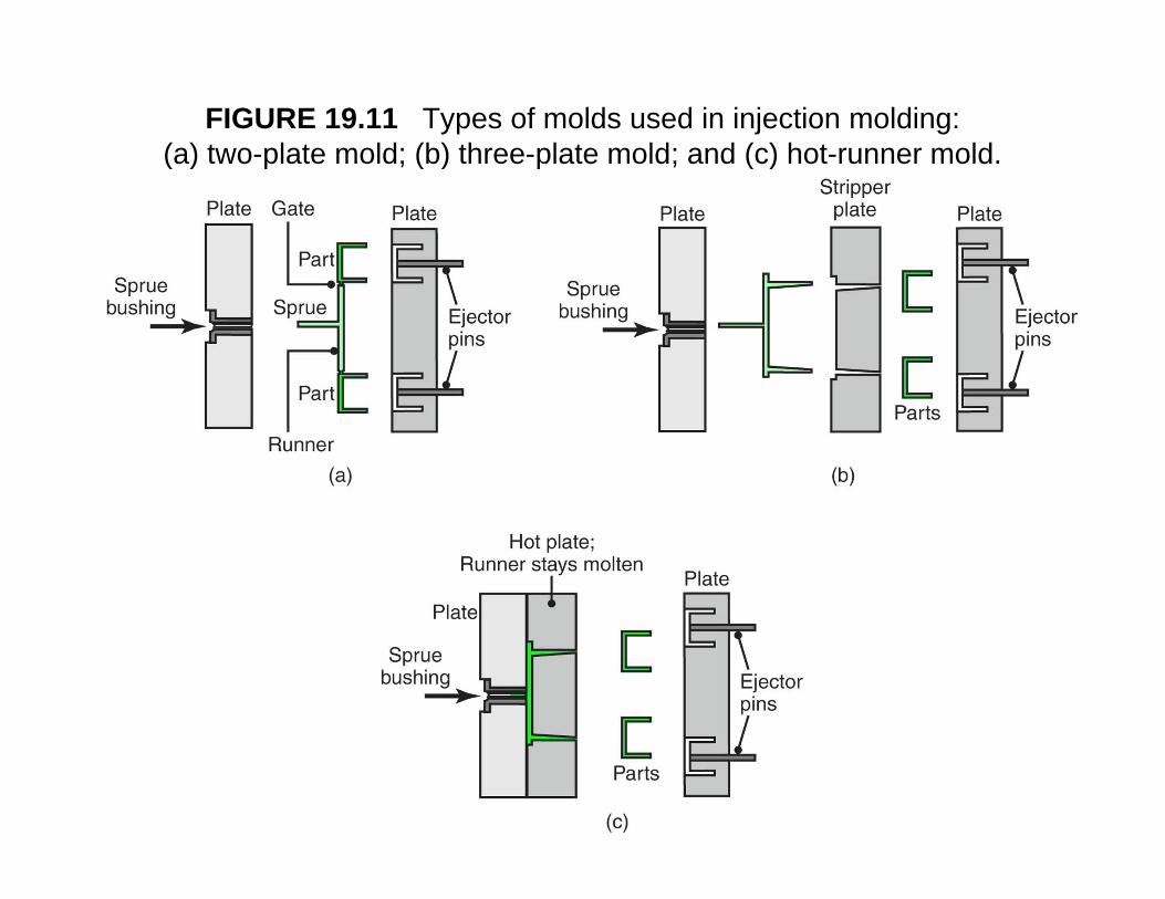
FIGURE 19.11 Types of molds used in injection molding: (a) two-plate mold; (b) three-plate mold; and (c) hot-runner mold.( ) p ; ( ) p ; ( )
Injection MoldingInjection Molding
• High rate production processHigh rate production process• Permits good dimensional control
V til d l• Versatile process can produce complex shapes
• Reduce defects by:– Good mold design– Control of material flow in die cavity
Injection Molding: Sources of Defects • Weld lines (similar to cold shut in metal
casting)• Unfilled die cavity if have premature
solidification due to narrow runners• Form flash if dies do not mate properly• Sink marks form at thick sections due to
uneven cooling causing local shrinkageAvoid defects by:y- Temperature control- Proper pressuresProper pressures- Simulate processes using computer software
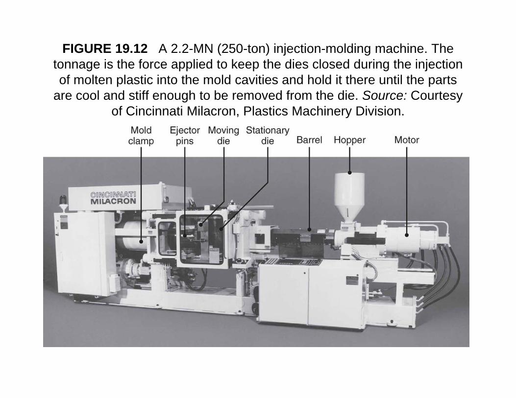
FIGURE 19.12 A 2.2-MN (250-ton) injection-molding machine. The tonnage is the force applied to keep the dies closed during the injection of molten plastic into the mold cavities and hold it there until the parts
are cool and stiff enough to be removed from the die. Source: Courtesy of Cincinnati Milacron, Plastics Machinery Division.
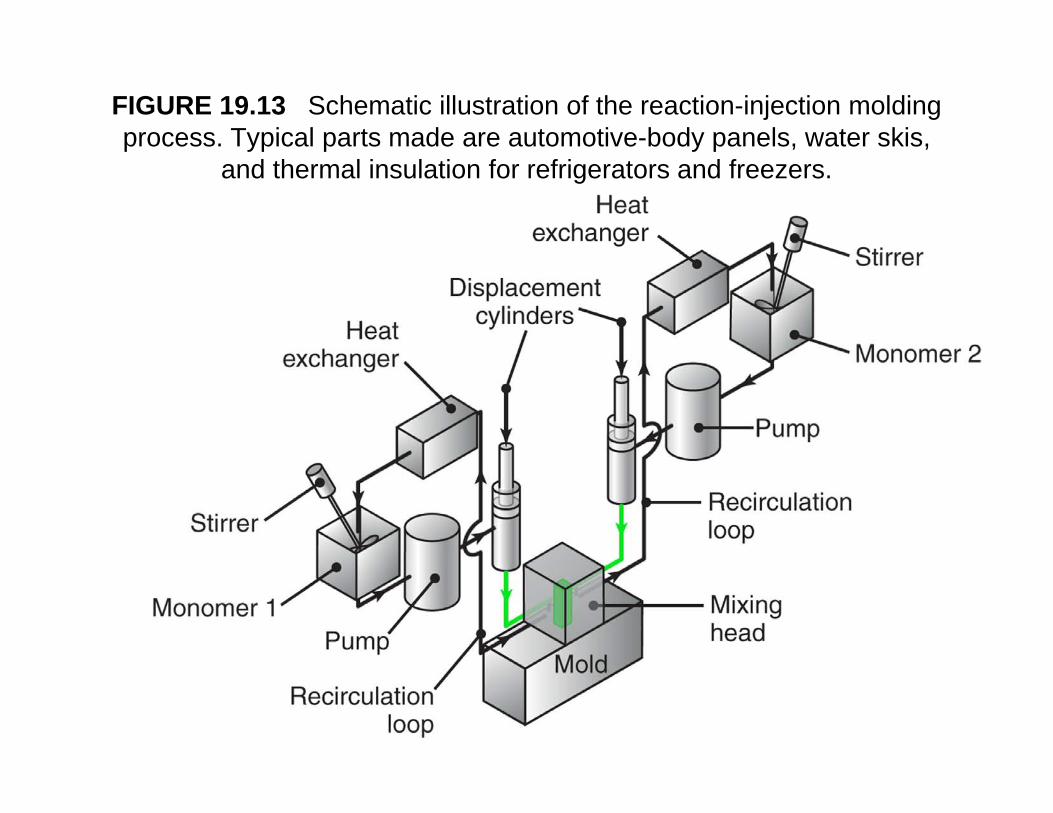
FIGURE 19.13 Schematic illustration of the reaction-injection molding process. Typical parts made are automotive-body panels, water skis, p yp p y p
and thermal insulation for refrigerators and freezers.
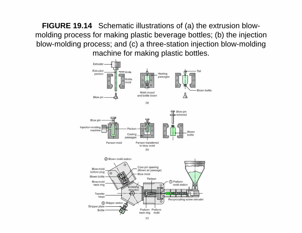
FIGURE 19.14 Schematic illustrations of (a) the extrusion blow-molding process for making plastic beverage bottles; (b) the injection blow molding process; and (c) a three station injection blow moldingblow-molding process; and (c) a three-station injection blow-molding
machine for making plastic bottles.
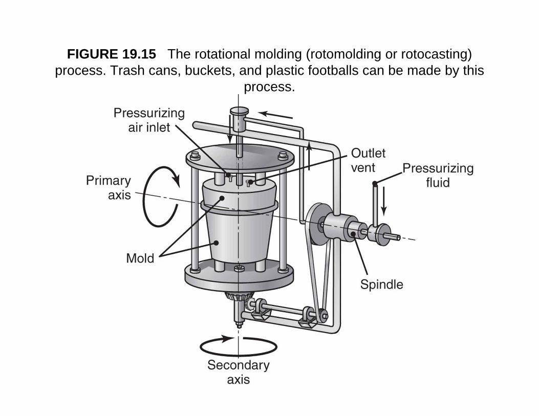
FIGURE 19.15 The rotational molding (rotomolding or rotocasting) process. Trash cans, buckets, and plastic footballs can be made by this p p y
process.
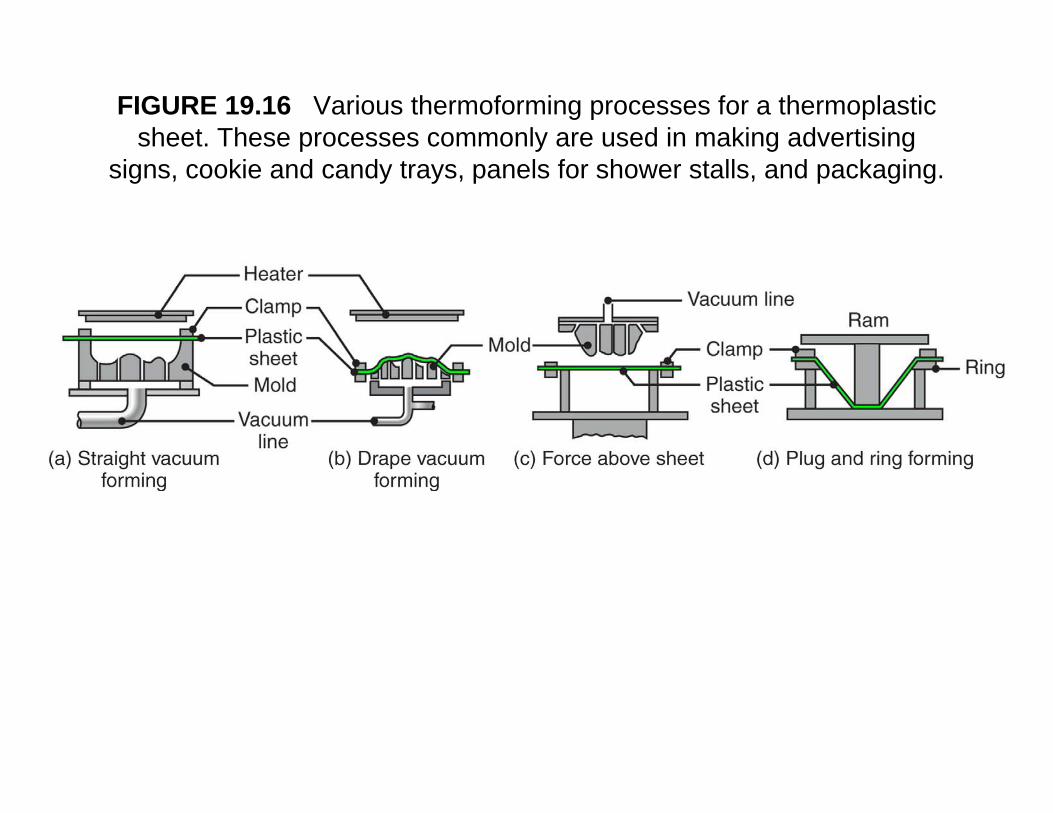
FIGURE 19.16 Various thermoforming processes for a thermoplastic sheet. These processes commonly are used in making advertising p y g g
signs, cookie and candy trays, panels for shower stalls, and packaging.
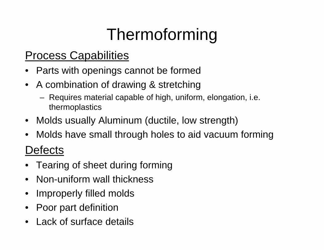
Thermoforming Process Capabilities• Parts with openings cannot be formed• A combination of drawing & stretching
– Requires material capable of high, uniform, elongation, i.e. thermoplasticsthermoplastics
• Molds usually Aluminum (ductile, low strength)• Molds have small through holes to aid vacuum formingDefects• Tearing of sheet during forming• Non-uniform wall thickness• Improperly filled molds
P t d fi iti• Poor part definition• Lack of surface details
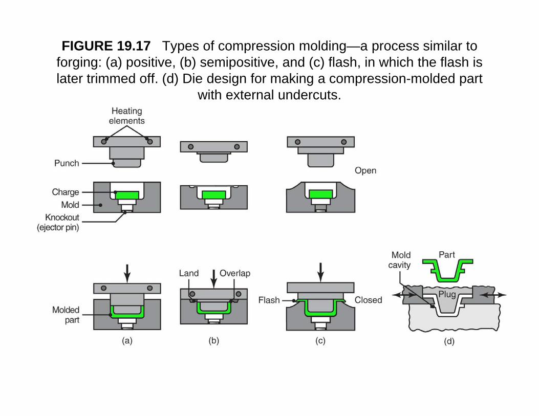
FIGURE 19.17 Types of compression molding—a process similar to forging: (a) positive, (b) semipositive, and (c) flash, in which the flash is later trimmed off (d) Die design for making a compression molded partlater trimmed off. (d) Die design for making a compression-molded part
with external undercuts.
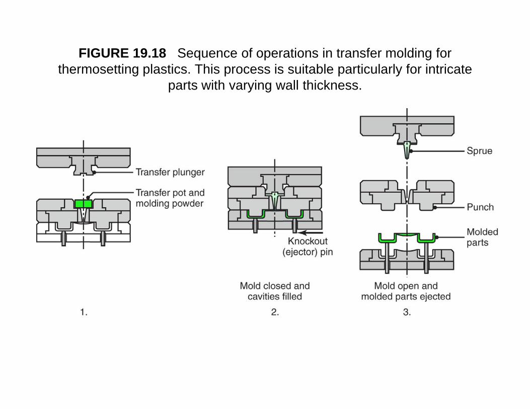
FIGURE 19.18 Sequence of operations in transfer molding for thermosetting plastics. This process is suitable particularly for intricate g p p p y
parts with varying wall thickness.
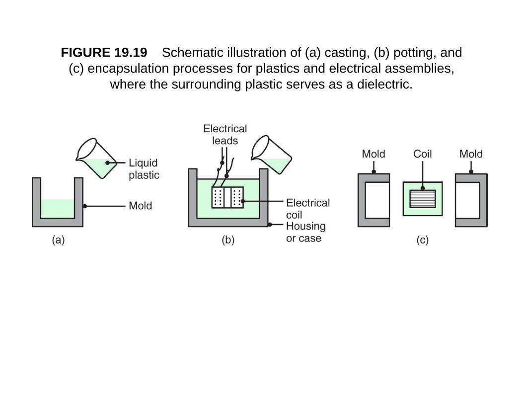
FIGURE 19.19 Schematic illustration of (a) casting, (b) potting, and (c) encapsulation processes for plastics and electrical assemblies, ( ) p p p
where the surrounding plastic serves as a dielectric.
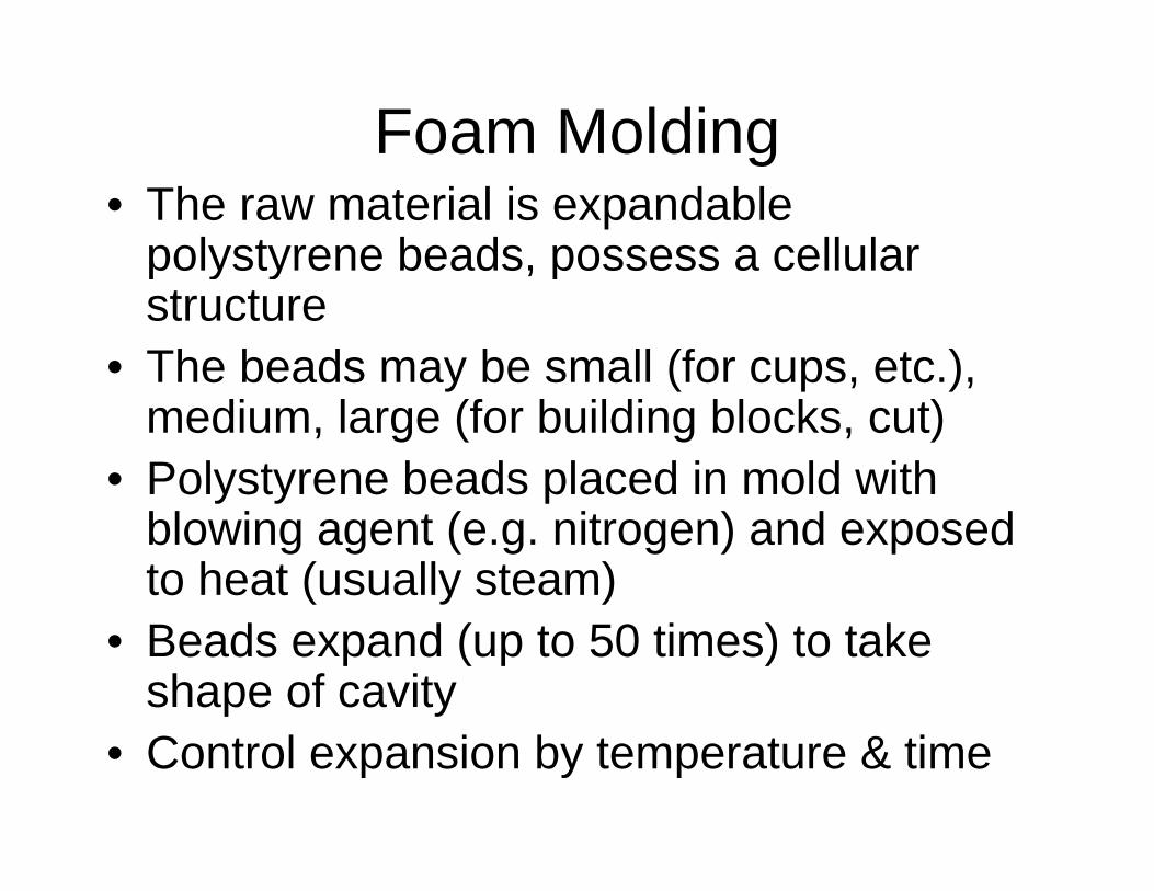
Foam Moldingg• The raw material is expandable
polystyrene beads, possess a cellular p y y pstructure
• The beads may be small (for cups, etc.), y ( p )medium, large (for building blocks, cut)
• Polystyrene beads placed in mold with y y pblowing agent (e.g. nitrogen) and exposed to heat (usually steam)
• Beads expand (up to 50 times) to take shape of cavity
• Control expansion by temperature & time
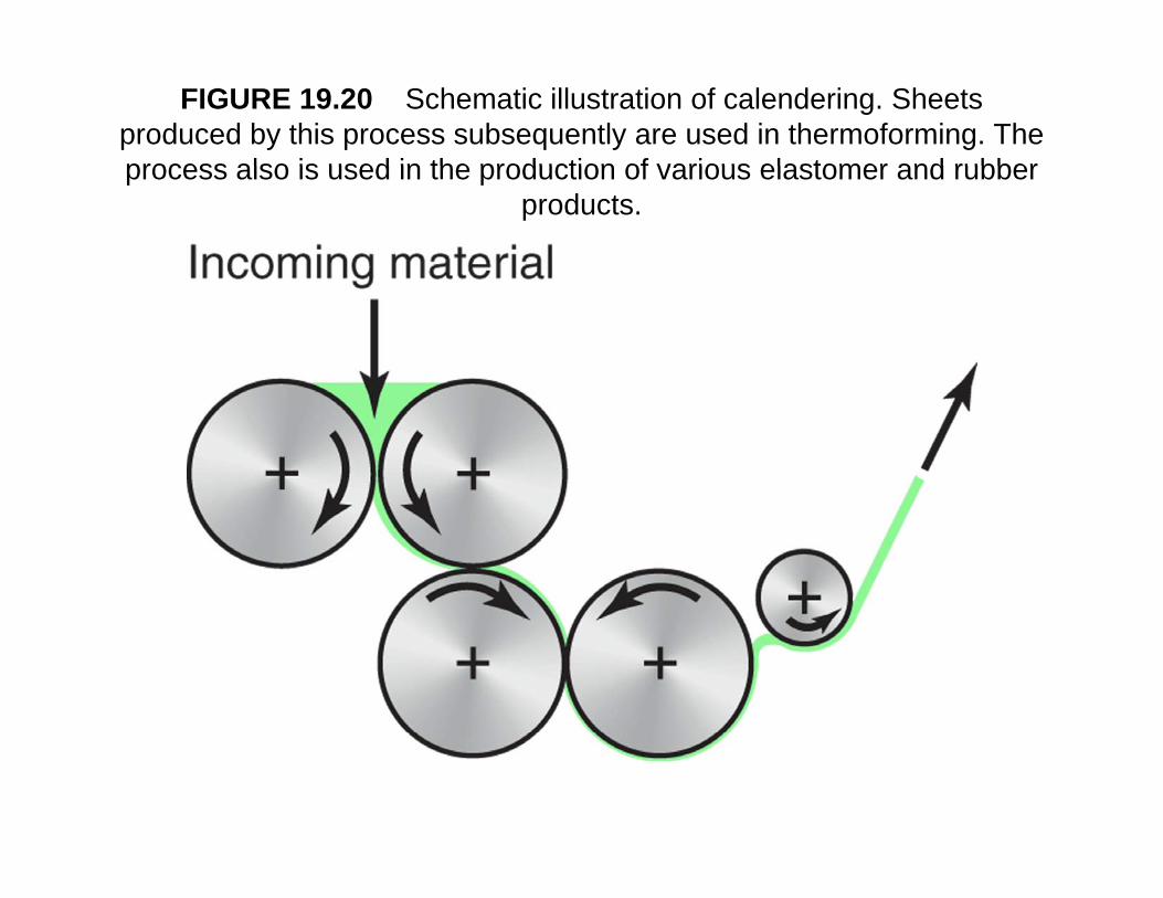
FIGURE 19.20 Schematic illustration of calendering. Sheets produced by this process subsequently are used in thermoforming. The process also is used in the production of various elastomer and rubberprocess also is used in the production of various elastomer and rubber
products.
Reinforced PlasticsReinforced Plastics- Are also known as polymer-matrix composites (PMC) p y p ( )
and fibre-reinforced plastics (FRP)- Consist of fibres in a polymer matrixCommon firbres are:Common firbres are:
- Glass, Carbon, Conductive graphite, Ceramic, Polymer, BoronMatrix - Support fibres in place; transfer stresses to fibres - Physically protect fibres- Reduce propagation of cracks in the composite- Reduce propagation of cracks in the composite- Usually TP or TS
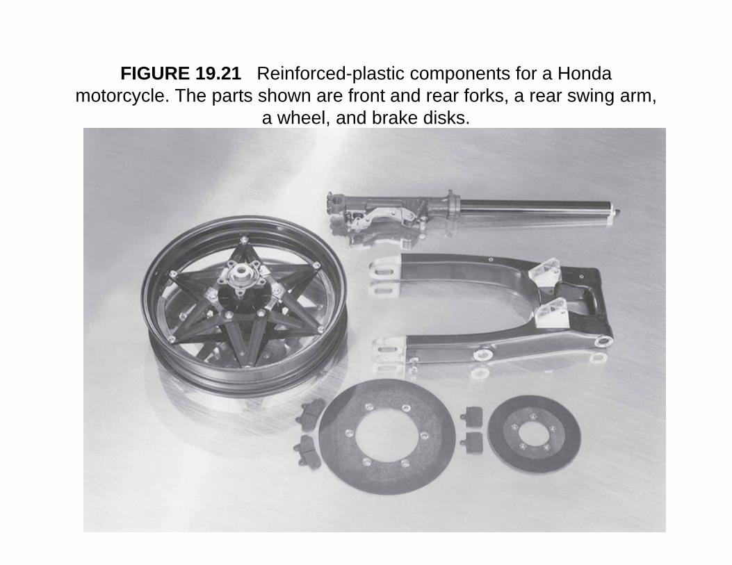
FIGURE 19.21 Reinforced-plastic components for a Honda motorcycle. The parts shown are front and rear forks, a rear swing arm, y p g
a wheel, and brake disks.
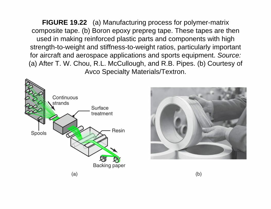
FIGURE 19.22 (a) Manufacturing process for polymer-matrix composite tape. (b) Boron epoxy prepreg tape. These tapes are then
used in making reinforced plastic parts and components with highused in making reinforced plastic parts and components with high strength-to-weight and stiffness-to-weight ratios, particularly important for aircraft and aerospace applications and sports equipment. Source: (a) After T W Chou R L McCullough and R B Pipes (b) Courtesy of(a) After T. W. Chou, R.L. McCullough, and R.B. Pipes. (b) Courtesy of
Avco Specialty Materials/Textron.
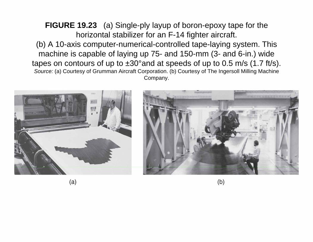
FIGURE 19.23 (a) Single-ply layup of boron-epoxy tape for the horizontal stabilizer for an F-14 fighter aircraft.
(b) A 10-axis computer-numerical-controlled tape-laying system This(b) A 10-axis computer-numerical-controlled tape-laying system. This machine is capable of laying up 75- and 150-mm (3- and 6-in.) wide
tapes on contours of up to ±30°and at speeds of up to 0.5 m/s (1.7 ft/s). Source: (a) Courtesy of Grumman Aircraft Corporation. (b) Courtesy of The Ingersoll Milling Machine
Company.
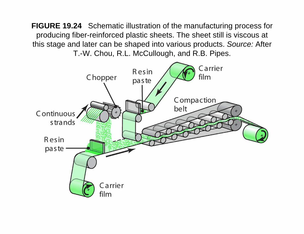
FIGURE 19.24 Schematic illustration of the manufacturing process for producing fiber-reinforced plastic sheets. The sheet still is viscous at
this stage and later can be shaped into various products Source: Afterthis stage and later can be shaped into various products. Source: After T.-W. Chou, R.L. McCullough, and R.B. Pipes.
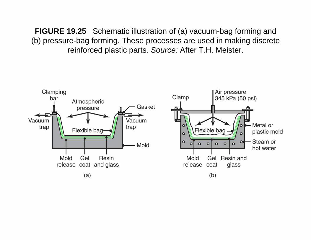
FIGURE 19.25 Schematic illustration of (a) vacuum-bag forming and (b) pressure-bag forming. These processes are used in making discrete ( ) p g g p g
reinforced plastic parts. Source: After T.H. Meister.
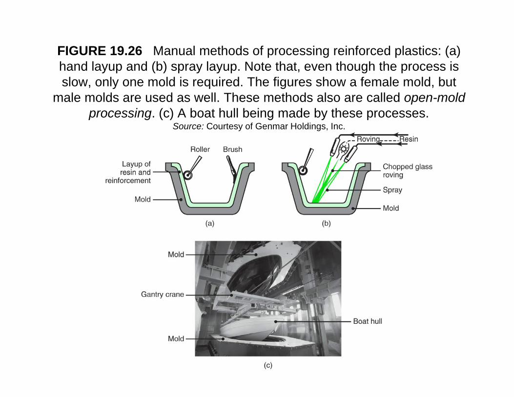
FIGURE 19.26 Manual methods of processing reinforced plastics: (a) hand layup and (b) spray layup. Note that, even though the process is slow, only one mold is required. The figures show a female mold, but
male molds are used as well. These methods also are called open-mold processing. (c) A boat hull being made by these processes.
S C t f G H ldi ISource: Courtesy of Genmar Holdings, Inc.
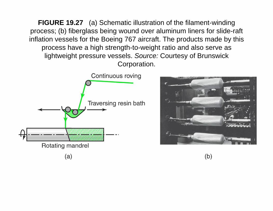
FIGURE 19.27 (a) Schematic illustration of the filament-winding process; (b) fiberglass being wound over aluminum liners for slide-raft inflation vessels for the Boeing 767 aircraft The products made by thisinflation vessels for the Boeing 767 aircraft. The products made by this
process have a high strength-to-weight ratio and also serve as lightweight pressure vessels. Source: Courtesy of Brunswick
CorporationCorporation.
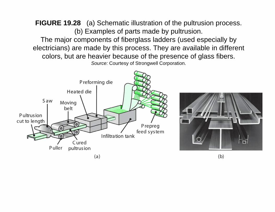
FIGURE 19.28 (a) Schematic illustration of the pultrusion process. (b) Examples of parts made by pultrusion.
The major components of fiberglass ladders (used especially byThe major components of fiberglass ladders (used especially by electricians) are made by this process. They are available in different
colors, but are heavier because of the presence of glass fibers. Source: Courtesy of Strongwell Corporation.
Quality Issues In Processing R i f d Pl iReinforced Plastics
• Major quality concern is occurrence of internalMajor quality concern is occurrence of internal voids and gaps between successive layers of material– Volatile gasses can develop during processing;
trapped gasses cause porosityR id b ll ( ) &/– Remove voids by roller (pressure) &/or vacuum
• Microcracks:Caused by Improper curing– Caused by Improper curing
– During transport and handling• Can detect internal defects by ultrasonic tests• Can detect internal defects by ultrasonic tests
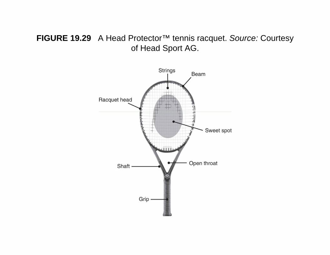
FIGURE 19.29 A Head Protector™ tennis racquet. Source: Courtesy of Head Sport AGof Head Sport AG.
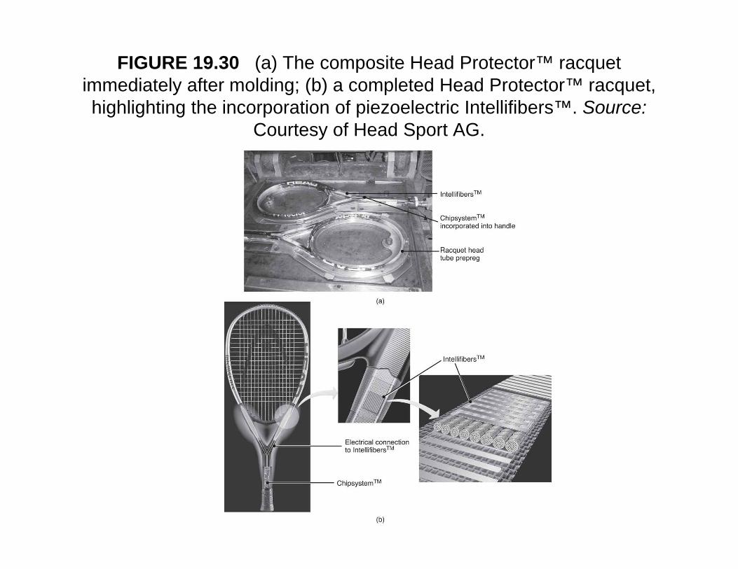
FIGURE 19.30 (a) The composite Head Protector™ racquet immediately after molding; (b) a completed Head Protector™ racquet, highlighting the incorporation of piezoelectric Intellifibers™ Source:highlighting the incorporation of piezoelectric Intellifibers™. Source:
Courtesy of Head Sport AG.
CompositesComposites
• A combination of two or more chemicallyA combination of two or more chemically distinct and insoluble phases with a recognizable interface in such a mannerrecognizable interface, in such a manner that its properties and structural performance are superior to those of theperformance are superior to those of the constituents acting independently
• Metal matrix Composites• Metal-matrix Composites• Ceramic-matrix Composites
Metal-matrix CompositesMetal matrix Composites
• Advantages of metal matrix over polymerAdvantages of metal matrix over polymer matrix:– Higher elastic modulusg– Higher toughness– Higher ductilityg y– Higher resistance to elevated temperatures
• Limitations:– Higher density– Greater difficulty processing parts
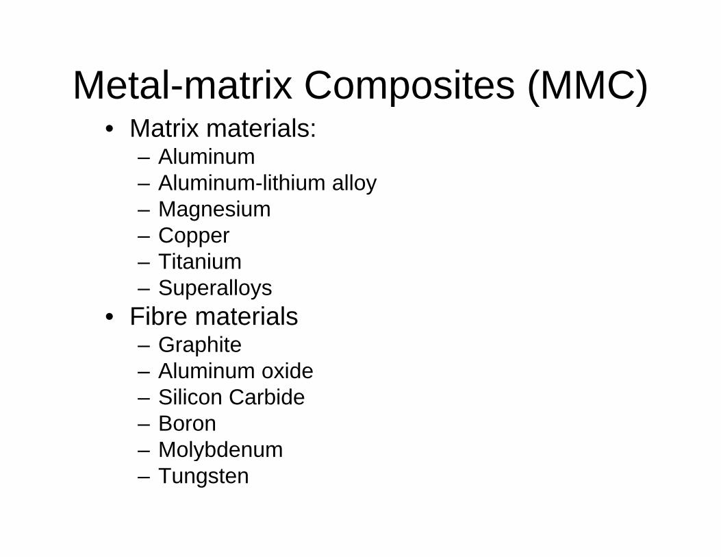
Metal-matrix Composites (MMC)p ( )• Matrix materials:
– Aluminum– Aluminum-lithium alloy– Magnesium– Copperpp– Titanium– Superalloys
• Fibre materials• Fibre materials– Graphite– Aluminum oxide– Silicon Carbide– Boron– MolybdenumMolybdenum– Tungsten
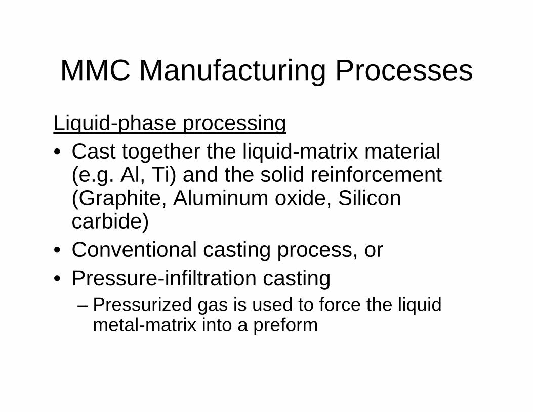
MMC Manufacturing ProcessesMMC Manufacturing Processes
Liquid-phase processingLiquid phase processing• Cast together the liquid-matrix material
(e.g. Al, Ti) and the solid reinforcement(e.g. Al, Ti) and the solid reinforcement (Graphite, Aluminum oxide, Silicon carbide) )
• Conventional casting process, or• Pressure-infiltration castingPressure infiltration casting
– Pressurized gas is used to force the liquid metal-matrix into a preform
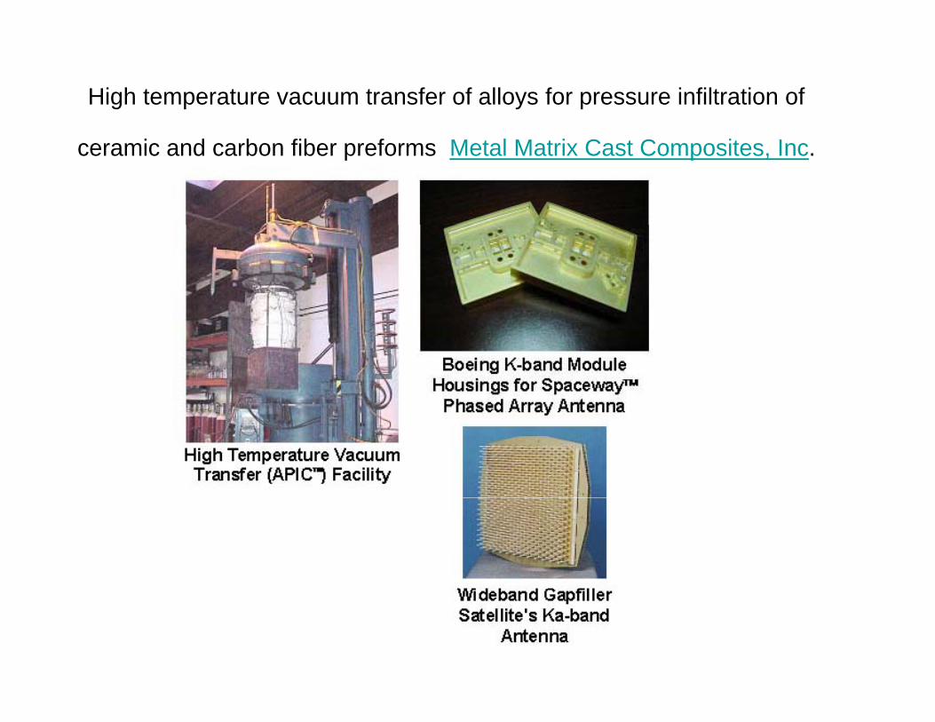
High temperature vacuum transfer of alloys for pressure infiltration of
ceramic and carbon fiber preforms Metal Matrix Cast Composites, Inc.
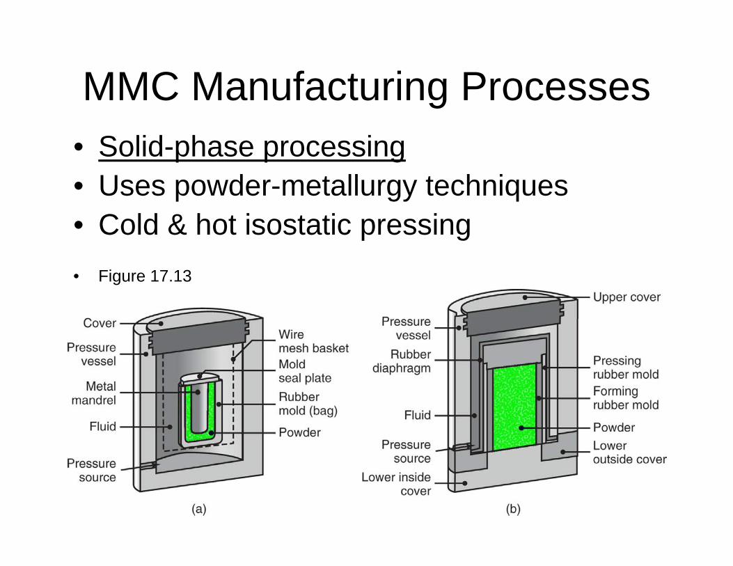
MMC Manufacturing Processesg• Solid-phase processing
U d t ll t h i• Uses powder-metallurgy techniques• Cold & hot isostatic pressing• Figure 17.13
MMC Manufacturing ProcessesMMC Manufacturing Processes
• Two-phase (liquid-solid) processingTwo phase (liquid solid) processing– Combines techniques of
• rheocasting• rheocasting, • spray atomization, • depositionp
Ceramic-matrix Composites (CMC)Ceramic matrix Composites (CMC)
• Have resistance to high temperatures and g pcorrosive environments
• Ceramics are strong & stiff but lack toughness• Matrix materials include:• Matrix materials include:
– Silicon carbide– Silicon nitride– Aluminum oxide– Mullite (compound of aluminum, silicon, oxygen)
• Fibre materials include:• Fibre materials include:– Carbon– Aluminum oxide
CMC Processes• Slurry infiltration
– Pass fibers through a slurry containing particles of the ceramic matrix, carrier liquid, organic binderorganic binder
– Wind the fibres infiltrated by the slurry onto a drum and drydrum and dry
– Stack the slurry impregnated fibres in a desired shapedesired shape
– Consolidate the matrix by hot pressing in a graphite die at high temperaturegraphite die at high temperature
CMC ProcessesCMC Processes
• Chemical-synthesisChemical synthesis
Ch i l I filt ti• Chemical-vapour Infiltration
Design Considerations i f i d h i f l iin forming and shaping of plastics
• Material selection considerations– Service requirementsService requirements– Long-term effects on properties
• Dimensional stability & weary– End of useful life disposal
Design Guidelines• Plastics manufacturing capability competitive with metals
(volume, speed, complex shapes); consider part properties appropriate to applicationappropriate to application
• Plastics have lower stiffness and strength than metals; consider design modifications, use of reinforced plastics
• Part requirements (shape, thickness, tolerances) can influence process selection
• Avoid large variations in cross-section area and thickness, g ,abrupt change in geometry
• Select shapes, material, properly for improved stiffness• Consider physical properties; avoid distortion warping• Consider physical properties; avoid distortion, warping• Consider work hardening and residual stresses• Consider directional strength of reinforced plasticsg p
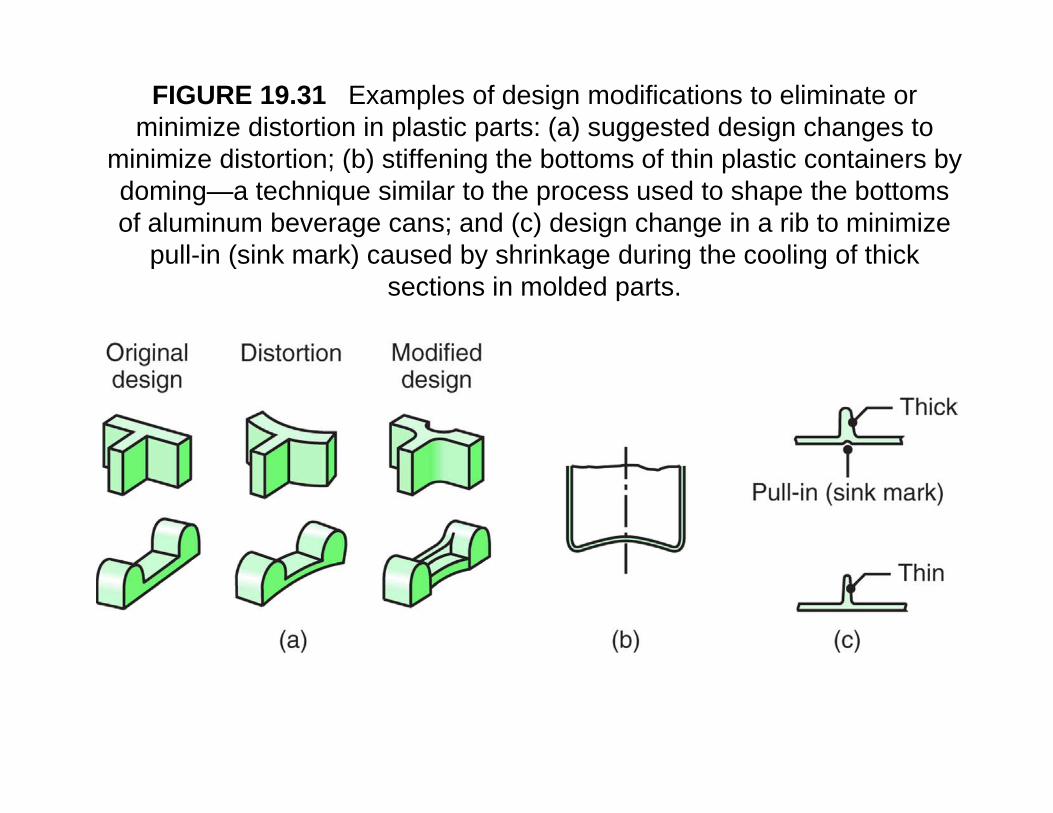
FIGURE 19.31 Examples of design modifications to eliminate or minimize distortion in plastic parts: (a) suggested design changes to i i i di t ti (b) tiff i th b tt f thi l ti t i bminimize distortion; (b) stiffening the bottoms of thin plastic containers by
doming—a technique similar to the process used to shape the bottoms of aluminum beverage cans; and (c) design change in a rib to minimize
pull in (sink mark) caused by shrinkage during the cooling of thickpull-in (sink mark) caused by shrinkage during the cooling of thick sections in molded parts.
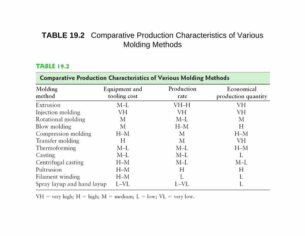
TABLE 19.2 Comparative Production Characteristics of Various Molding MethodsMolding Methods
Summaryy• TP shaped by many processes including extrusion,
molding, casting, thermoformingR t i l i f f l ll t d– Raw material in form of granules, pellets, powder
– TP can stretch; produce complex, deep shapes• TS generally molded or castTS generally molded or cast• TS better dimensional accuracy than TP• Fibre-reinforced plastics (stronger) produced by a
i t f th dvariety of methods• Design of plastic parts must consider low strength
and stiffness, other physical propertiesand stiffness, other physical properties• MMC and CMC processes continue development• Consider economics, comparing with metals:
hi di l ti d ti tmachinery, dies, cycle times, production rate, volume