Embed Size (px)
Citation preview
PLASTERBOARDINSTALLATION MANUALNEW ZEALAND
2
PLASTERBOARD INSTALLATION MANUAL FEBRUARY 2017
PREFACE ..................................................................................................................3INTRODUCTION ....................................................................................................3STANDARDS ...........................................................................................................3NZBC COMPLIANCE .............................................................................................3
PLASTERBOARD AND ITS PROPERTIES ......................4PLASTERBOARD FEATURES AND BENEFITS ............................................4PLASTERBOARD TYPES .....................................................................................4DIMENSIONAL STABILITY ..................................................................................5THERMAL RESISTANCE ......................................................................................5FIRE RESISTANCE ..................................................................................................5FIRE HAZARD PROPERTIES ..............................................................................5IMPACT RESISTANCE ...........................................................................................5MOISTURE RESISTANCE .....................................................................................5SUSTAINABILITY....................................................................................................6SAFETY ......................................................................................................................6FIRST AID ..................................................................................................................6
DESIGN CONSIDERATIONS...........................................7CONDENSATION ....................................................................................................7VENTILATION ..........................................................................................................7DEVICES GENERATING HEAT .......................................................................... 8ROOF SARKING ......................................................................................................8ACOUSTICS ..............................................................................................................8ATTACHMENTS .......................................................................................................9WALLS ON BOUNDARY ......................................................................................9ATTACHED DWELLINGS .....................................................................................9CONTROL JOINTS .................................................................................................9LEVELS OF FINISH ............................................................................................... 10GLANCING LIGHT .................................................................................................12
LINING MATERIALS ..................................................... 13PLASTERBOARD.................................................................................................. 13MATERIAL QUANTITIES .................................................................................... 15DELIVERY, HANDLING AND STORAGE ....................................................... 16
FRAMING ...................................................................... 17FRAMING CHECK ..................................................................................................17FIXING FACE REQUIREMENTS .........................................................................17TIMBER FRAMING.................................................................................................17STEEL FRAMING....................................................................................................17
LININGS LAYOUT ......................................................... 18
PLASTERBOARD FIXING ............................................. 19FASTENING SYSTEMS ........................................................................................ 19GENERAL SCREW AND NAIL FIXING........................................................... 19PLASTERBOARD FASTENERS ........................................................................ 19
INTERNAL CEILINGS .................................................. 20CEILING LOADS AND SPANS ..........................................................................20CEILING SUPPORT OPTIONS .......................................................................... 21METAL SUSPENDED OR DIRECT FIXED SYSTEMS ................................. 22CONTROL JOINTS .............................................................................................. 23FIXING TO CEILINGS .......................................................................................... 23
TABLE OF CONTENTS
GARAGE AND EXTERNAL CEILINGS ..........................27GENERAL ................................................................................................................27DESIGN NOTES .....................................................................................................27INSTALLATION OF GARAGE CEILINGS ...................................................... 28INSTALLATION OF EXTERNAL CEILINGS ................................................. 29
FRAMED WALLS .......................................................... 31FIXING WITH COMBINATION OF ADHESIVE AND FASTENERS ........ 31FIXING WITH SCREWS ONLY .......................................................................... 31FIXING WITH NAILS ONLY ................................................................................32BUTT JOINTS IN WALLS ....................................................................................32INTERNAL CORNERS ........................................................................................ 33CONTROL JOINT INSTALLATION ................................................................. 34DOOR JAMBS ....................................................................................................... 35SHADOWLINE STOPPING ANGLE ................................................................ 35WALL-CEILING JUNCTIONS ........................................................................... 36
MASONRY WALLS .......................................................37GENERAL ................................................................................................................37INSTALLATION USING MASONRY ADHESIVE METHOD ......................37INSTALLATION USING FURRING CHANNELS ......................................... 39
WET AREAS ................................................................. 40REGULATORY REQUIREMENTS ....................................................................40USG BORAL WET AREA ................................................................................... 42
CURVES AND ARCHES .................................................53CONSTRUCTING CURVED WALLS AND CEILINGS ................................ 53ARCHES .................................................................................................................. 53
CORNICES ....................................................................55USG BORAL CORNICES .................................................................................... 55HANDLING AND LAYOUT ................................................................................ 56CUTTING CORNICE ............................................................................................ 56FIXING CORNICE ..................................................................................................57MIXING CORNICE ADHESIVE ..........................................................................57
JOINTING .....................................................................58GENERAL ............................................................................................................... 58JOINTING COMPOUNDS .................................................................................. 58USG BORAL JOINTING COMPOUNDS ........................................................ 59JOINTING TAPES .................................................................................................60STOPPING RECESSED JOINTS ......................................................................60STOPPING BUTT JOINTS ................................................................................. 62STOPPING CORNERS ........................................................................................ 63
TOOLS AND ACCESSORIES .........................................65MECHANICAL JOINTING TOOLS ..................................................................66
DECORATING PLASTERBOARD LININGS ..................67
CONTACTS ................................................................... 68
3
PLASTERBOARD INSTALLATION MANUAL FEBRUARY 2017
PREFACEUSG Boral Building Products is a plasterboard and ceilings Joint Venture between USG Corporation and Boral Limited, and is one of the leading players in this field.
Operating throughout Asia, Australasia and in the Middle East, USG Boral Building Products combines USG’s innovative building products technologies with Boral’s extensive plasterboard manufacturing and distribution footprint in Asia and Australia.
USG Boral Building Products is well positioned to service the Australasian market through its manufacturing facilities in New South Wales, Queensland, Victoria and Auckland.
For more information on USG Boral Building Products refer to www.usgboral.com
INTRODUCTIONThis manual is intended for use by specifiers, plastering contractors and builders. It outlines recommended methods for installation, jointing and finishing of USG Boral plasterboard linings in non-fire rated residential construction including general areas, wet areas, garage ceilings and protected external ceilings.
Refer USG Boral relevant system publications for fire rated and acoustic construction details.
While this manual outlines plasterboard installation specification for timber framed construction, similar installation, jointing and finishing details apply to steel framed buildings. Refer relevant USG Boral publications for steel framed plasterboard construction details.
Installation specifications outlined in this manual apply to Level 4 finish, unless noted otherwise (see Levels of Finish).
STANDARDSThe following Australian, New Zealand and other Standards are referenced in this publication:
• AS/NZS 2588 Gypsum plasterboard
• AS/NZS 2589 Gypsum linings — Application and finishing
• AS 3740 Waterproofing of domestic wet areas
• AS/NZS 4858 Wet area membranes
• NZS 3604 Timber framed buildings
• NZS 1170.5 Earthquake actions
• AS/NZS 1170.2 Wind actions
• AS 1397 Steel sheet and strip — hot dipped, zinc coated or aluminium/zinc coated
• AS 3700 Masonry structures
• AS/NZS 2918 Domestic solid-fuel burning appliances — Installation
• AS/NZS 5601 Gas installations
• National Association of steel-framed housing (NASH) standard for residential and low-rise steel framing
• AS 3566 Self-drilling screws for the building and construction industries
• AS 2753 Adhesives - Mastic - For bonding gymsum plaster linings to wood and metal framing members
• AS 1145.3 Determination of tensile properties of plastic materials Part 3: Test conditions for films and sheets
• AS/NZS 1716 Respiratory protective devices
• ISO 9001 Quality systems — Model for quality assurance in production, installation and servicing
• AS/NZS 2311 The painting of buildings
• AS/NZS 4600 Cold-formed steel structures.
NZBC COMPLIANCEUSG Boral has all the necessary evidence to support its plasterboard compliance with the relevant provisions of the New Zealand Building Code (NZBC).
USG Boral Plasterboard complies with NZBC:
• Structure B1
• Durability B2
• Spread of Fire C3
• Internal Moisture E3
• Hazardous Building Mat F2
• Ventilation G4
• Airborne/Impact Sound G6
Invented by USG more than 100 years ago, plasterboard has become the most common dry lining material for walls and ceilings in modern building construction. A breakthrough SHEETROCK® technology developed by USG in recent years has resulted in a lighter and at the same time stronger product than standard plasterboard.
Manufactured on a continuous production line, plasterboard is comprised of a specially formulated gypsum core encased between heavy duty paper liners. Locally manufactured USG Boral plasterboard products utilise naturally occurring gypsum and 100% recycled paper.
Plasterboard sheets are commonly available in 1200mm and 1350mm widths and have recessed longitudinal edges facilitating a smooth, seamless joint finish.
USG Boral plasterboard products meet the requirements of AS/NZS 2588 Gypsum plasterboard.
PLASTERBOARD FEATURES AND BENEFITS• Lightweight
• Cost effective
• Versatile
• Easy to install to timber, steel and masonry substrates
• Provides smooth, stable base for paint and other decorative finishes
• Contains recycled materials.
4
PLASTERBOARD INSTALLATION MANUAL FEBRUARY 2017
PLASTERBOARD AND ITS PROPERTIES
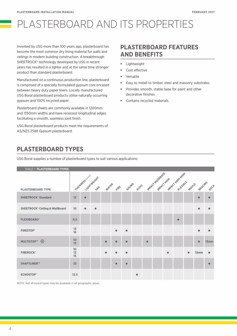
PLASTERBOARD TYPESUSG Boral supplies a number of plasterboard types to suit various applications:
TABLE 1: PLASTERBOARD TYPES
PLASTERBOARD TYPE
SHEETROCK® Standard 13 • • •
SHEETROCK® Ceiling & WallBoard 10 • • • •
FLEXIBOARD® 6.5 •
FIRESTOP® 13 16 • • • •
MULTISTOP™ 10 13 • • • • • 13mm
FIBEROCK®10 13 16
• • • • • 13mm •
SHAFTLINER™ 25 • • •
ECHOSTOP® 12.5 •
SAGIM
PACT MODERATE
THICKNESS (m
m)
IMPACT H
IGH
IMPACT VERY H
IGH
MOULD
BRACING
NOTE: Not all board types may be available in all geographic areas.
5
PLASTERBOARD INSTALLATION MANUAL FEBRUARY 2017
DIMENSIONAL STABILITYUnder normal ambient temperature and humidity conditions, plasterboard has the following expansion properties:
Thermal Coefficient of Linear Expansion: 16.2 x 10⁻⁶ mm / (mm°C) at temperature range 4 to 38°C
Hygrometric Coefficient of Expansion: 7.2 x 10⁻⁶ mm / mm%RH (5 to 90%RH)
THERMAL RESISTANCEThe R-values of some USG Boral products are provided in the following table:
TABLE 2: THERMAL RESISTANCE
PLASTERBOARD TYPE R-VALUE
10mm SHEETROCK 0.056m2 K/W ±10%
13mm SHEETROCK 0.073m2 K/W ±10%
10mm FIBEROCK 0.038m2 K/W ±10%
13mm FIBEROCK 0.049m2 K/W ±10%
FIRE RESISTANCEPlasterboard is deemed to be a non-combustible material for the purposes of the New Zealand Building Code.
While plasterboard inherently possesses a certain degree of fire resistance due to the chemical composition of the gypsum core, the following USG Boral products have enhanced fire resistance properties and are specifically formulated for use in fire rated construction:
• FIRESTOP
• MULTISTOP
• FIBEROCK
• SHAFTLINER
FIRE HAZARD PROPERTIESWall and ceiling lining materials in certain types of buildings must comply with the Fire Hazard Properties requirements of the NZBC.
All USG Boral plasterboard lining products are classified as Group 1-S (least hazardous) materials and have a smoke growth rate index less than 100 and average specific extinction area less than 250 m2/kg when tested in accordance with the ISO 5660.
IMPACT RESISTANCEUSG Boral offers a number of lining products specifically developed for applications requiring enhanced impact resistance:
TABLE 3: IMPACT RESISTANT LINING PRODUCTS
PRODUCT RELATIVE IMPACT RESISTANCE
MULTISTOP Moderate
FIBEROCK Very high
MOISTURE RESISTANCEAlthough plasterboard is not a waterproof material, USG Boral offers a number of lining products classified as moisture resistant under the NZBC requirements for domestic wet areas. These products include:
• FIBEROCK
• MULTISTOP 4
Plasterboard linings must have suitable surface protection in accordance with NZBC E3/AS1
» PLASTERBOARD AND ITS PROPERTIES
6
PLASTERBOARD INSTALLATION MANUAL FEBRUARY 2017
SUSTAINABILITY
RAW MATERIALSGypsum used in locally manufactured USG Boral plasterboard products is mined from abundant resources at Kevin in South Australia. The mine has in place a rehabilitation and revegetation strategy aimed at creating a landscape with natural appearance and native local vegetation.
Plasterboard paper liner is manufactured from 100% recycled waste paper fibre and contains no virgin paper fibre.
FIBEROCK gypsum board contains 95% recycled content.
PLASTERBOARD MANUFACTUREApart from natural gypsum and recycled paper, the key inputs in the plasterboard manufacturing process are natural gas and potable water.
All USG Boral Australia plasterboard production facilities are certified under ISO 9002 Quality systems — Model for quality assurance in production, installation and servicing.
USG Boral aims at exceeding the local Environment Protection requirements and at maximising the use of recycled water at its manufacturing facilities.
PLASTERBOARD RECYCLINGPlasterboard waste can be recycled into new plasterboard or as soil conditioner.
For further information contact your local USG Boral office.
SAFETYThe following precautions are recommended when installing and finishing plasterboard:
• Avoid creating dust when handling plasterboard or mixing jointing compounds.
• When sanding, minimise the effects of dust by:
− providing adequate ventilation
− wearing eye protection
− wearing a respiratory mask conforming to AS/NZS 1716 Respiratory protective devices
− using mechanical sanding tools fitted with dust extractor and storage bag.
• Keep tools and materials out of reach of children.
In addition, the users should observe Occupational Health and Safety tips contained on the packaging labels for USG Boral products as well as safe manual handling practices.
FIRST AID• If plaster compound or dust comes into contact with the
eyes, wash eyes thoroughly with clean potable water.
• If plaster compound or dust comes into contact with skin, wash skin thoroughly with soap and water.
• If dust is inhaled, move to a fresh air environment.
• If plastering compound or dust is ingested, drink plenty of water.
Material Safety Data Sheets for USG Boral products can be downloaded from www.usgboral.com
In emergencies call 0800 874 267 (USG Boral NZ)
For poison assistance call 0800 764 766 New Zealand National Poison Centre
» PLASTERBOARD AND ITS PROPERTIES
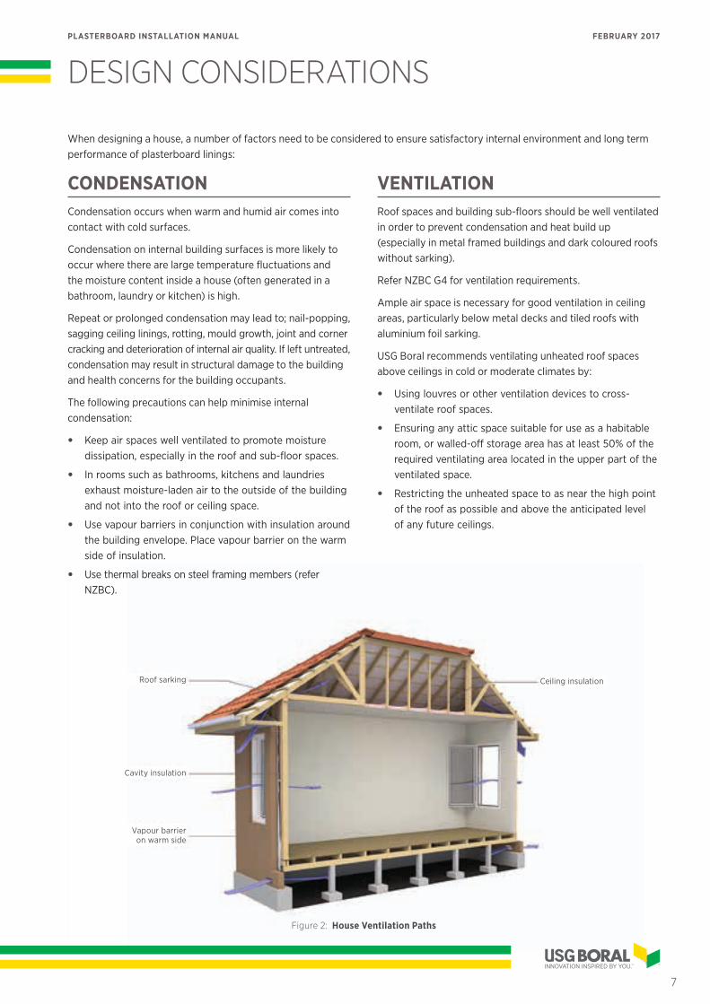
Ceiling insulationRoof sarking
Cavity insulation
Vapour barrier on warm side
7
PLASTERBOARD INSTALLATION MANUAL FEBRUARY 2017
When designing a house, a number of factors need to be considered to ensure satisfactory internal environment and long term performance of plasterboard linings:
CONDENSATIONCondensation occurs when warm and humid air comes into contact with cold surfaces.
Condensation on internal building surfaces is more likely to occur where there are large temperature fluctuations and the moisture content inside a house (often generated in a bathroom, laundry or kitchen) is high.
Repeat or prolonged condensation may lead to; nail-popping, sagging ceiling linings, rotting, mould growth, joint and corner cracking and deterioration of internal air quality. If left untreated, condensation may result in structural damage to the building and health concerns for the building occupants.
The following precautions can help minimise internal condensation:
• Keep air spaces well ventilated to promote moisture dissipation, especially in the roof and sub-floor spaces.
• In rooms such as bathrooms, kitchens and laundries exhaust moisture-laden air to the outside of the building and not into the roof or ceiling space.
• Use vapour barriers in conjunction with insulation around the building envelope. Place vapour barrier on the warm side of insulation.
• Use thermal breaks on steel framing members (refer NZBC).
VENTILATIONRoof spaces and building sub-floors should be well ventilated in order to prevent condensation and heat build up (especially in metal framed buildings and dark coloured roofs without sarking).
Refer NZBC G4 for ventilation requirements.
Ample air space is necessary for good ventilation in ceiling areas, particularly below metal decks and tiled roofs with aluminium foil sarking.
USG Boral recommends ventilating unheated roof spaces above ceilings in cold or moderate climates by:
• Using louvres or other ventilation devices to cross-ventilate roof spaces.
• Ensuring any attic space suitable for use as a habitable room, or walled-off storage area has at least 50% of the required ventilating area located in the upper part of the ventilated space.
• Restricting the unheated space to as near the high point of the roof as possible and above the anticipated level of any future ceilings.
DESIGN CONSIDERATIONS
Figure 2: House Ventilation Paths
8
PLASTERBOARD INSTALLATION MANUAL FEBRUARY 2017
» DESIGN CONSIDERATIONS
DEVICES GENERATING HEATUSG Boral Plasterboard does not recommend the use of radiant heating systems continuously subjecting plasterboard ceilings to temperatures in excess of 42°C.
Prolonged exposure to temperatures higher than 42°C may cause changes in the chemical composition of the gypsum core and a loss of plasterboard integrity over time.
The following regulatory and normative requirements must be followed in order to prevent plasterboard deterioration due to excessive temperatures from heat generating devices:
• NZBC provisions for installation of heating appliances, fireplaces, chimneys and flues
• AS/NZS 2918 Domestic solid-fuel burning appliances — Installation
• AS/NZS 5601 Gas installations.
In accordance with AS/NZS 5601, gypsum based wall boards within 200mm of the edge of the nearest burner must be protected to a height of not less than 150mm above the periphery of that burner and for the full length of the cooking surface area with a fire resistant facing material. In no case the periphery of the burner should be closer than 140mm to wall linings.
6mm fibre cement board constitutes an acceptable method of protection for 10mm plasterboard in domestic installations.
13mm FIBEROCK complies with requirements of AS/NZS 5601 for fire resistant materials behind 5mm toughened glass or stainless steel splashbacks in non-load carrying situations.
Refer splashback fire protection requirements by relevant State and Territory authorities.
ROOF SARKINGRoof sarking can reduce the risk of condensation and also provides protection from the elements such as wind, dust and rain.
Sarking is strongly recommended under tiled roofs in order to prevent ceiling damage due to rain blowback.
ACOUSTICSEffective sound isolation is an essential element of functional house design.
Unwanted noise may emanate from external sources such as traffic or neighbouring properties, or from internal sources such as home entertainment systems or plumbing.
Common design factors that can influence the level of noise within a house include:
• House orientation
• Internal layout
• Location of doors and windows
• Placement of power points, downlights and other services penetrations
• Placement of plumbing and heating/air conditioning services
• Location of appliances and audio visual equipment.
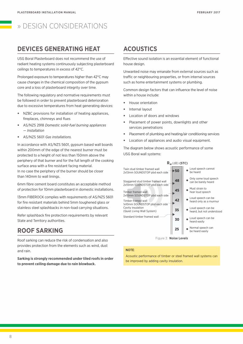
The diagram below shows acoustic performance of some
USG Boral wall systems:
Figure 3: Noise Levels
NOTE:
Acoustic performance of timber or steel framed wall systems can be improved by adding cavity insulation.
Rw (dB) (STC)
25
30
35
42
45
48
50
Normal speech can be heard easily
Loud speech can be heard easily
Loud speech can be heard, but not understood
Loud speech can be heard only as a murmur
Must strain to hear loud speech
Only some loud speech can be barely heard
Loud speech cannot be heard
Standard timber framed wall
Timber framed wall1x10mm SOUNDSTOP pbd each sideCavity insulation(Quiet Living Wall System)
Timber framed wall2x10mm SOUNDSTOP pbd each side
Staggered stud timber framed wall 2x10mm SOUNDSTOP pbd each side
Twin stud timber framed wall 2x13mm SOUNDSTOP pbd each side
9
PLASTERBOARD INSTALLATION MANUAL FEBRUARY 2017
» DESIGN CONSIDERATIONS
ATTACHMENTSA wide range of proprietary fixings are available for attaching light fixtures directly to plasterboard linings. Such fixings should be used in accordance with manufacturers' instructions and should not support loads in excess of maximum allowed.
Heavy loads must be fixed directly into the studs or noggings with appropriate fasteners.
The following point loads can be supported directly by FIBEROCK linings:
TABLE 5: MAXIMUM LOADS ON FIBEROCK
FIBEROCK THICKNESS
MAXIMUM POINT LOAD PARALLEL TO THE BOARD*
10mm 10kg
13mm 13kg
16mm 16kg
* Loads applied at the head of a single 8 gauge high thread screw inserted sufficiently to allow the parallel thread section of the screw to be in contact with the full depth of the FIBEROCK lining.
NOTE:
Wall framing must be checked for its capacity to carry attached loads.
WALLS ON BOUNDARYAccording to NZBC, external walls on or in close proximity to the boundary are required to be fire rated (refer NZBC C3.7–3.9 for fire rating requirements). USG Boral OutRwall® lightweight external wall systems have been specifically designed for this application and are available in fire ratings up to FRR 90/90/90.
For more information refer to www.usgboral.com
ATTACHED DWELLINGSSeparating walls between attached dwellings must satisfy NZBC fire rating and acoustic requirements.
USG Boral Partiwall lightweight separating wall systems have been specifically designed to suit New Zealand construction methods and are available in fire ratings up to FRR 90/90/90 and acoustic ratings up to STC 66.
For more information refer to www.usgboral.com
CONTROL JOINTSPlasterboard linings are not designed to withstand stresses due to structural movements or excessive changes in temperature or humidity.
Potential stress build up and cracking can be minimised by incorporating control joints as follows:
• Provide control joints in walls and ceilings at maximum 12m intervals in both directions (max 6m intervals in external ceilings) and at every change of lining material type (ie gypsum board to fibre cement).
• Provide horizontal control joints at mid-floors in stairwells in multi-storey buildings.
• Place plasterboard control joints over movement joints in the substrate or structural elements and at every change of substrate material.
• Utilise floor to ceiling openings as control joints.
• Fit double studs or joists, spaced slightly apart, in the frame at control joint locations (refer Framed Walls – Control Joints on page 34).
• Control joints should extend through cornice.
• Ceiling battens should be discontinued at control joint locations.
• Control joints can be formed by fitting #093 Control Joint or plastic expansion beads that leave a neat, clean and flexible joint (see Control Joint installation instructions on page 34).
NOTE:
Proprietary control joint sections are designed to accommodate normal expansion/contraction movements in plasterboard linings and substrates, and not significant structural movements.
Other solutions may be required in such situations.
10
PLASTERBOARD INSTALLATION MANUAL FEBRUARY 2017
» DESIGN CONSIDERATIONS
LEVELS OF FINISHThe term ‘Level of Finish’ applies to plasterboard linings prior to decoration.
AS/NZS 2589 Gypsum linings — Application and finishing defines three levels of finish: 3, 4 and 5. Level 4 is the default level of finish for plasterboard linings, unless specified otherwise.
It is essential that the level of finish is determined at the design stage since each level has specific requirements for substrate tolerances and plasterboard installation, jointing and finishing. The desired level of finish may not be achieved unless all of these requirements are met through various stages of construction.
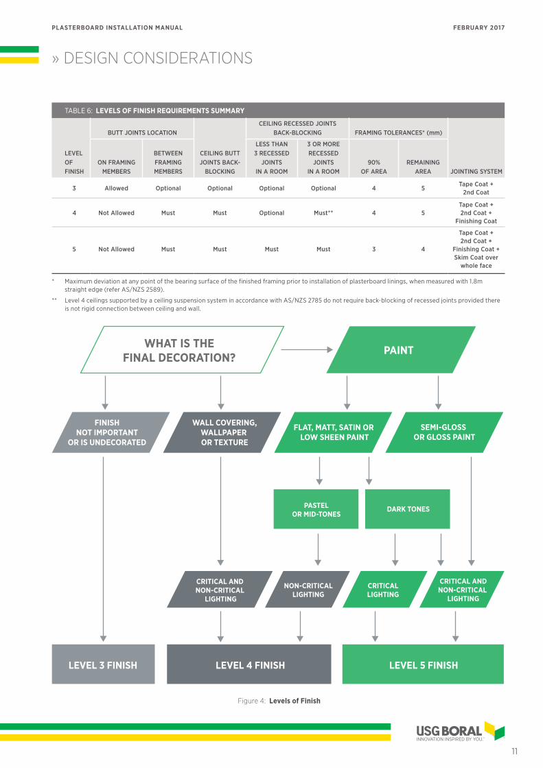
Levels of finish recommended for various lighting conditions and surface decorations are shown in Figure 4.
For the full description of levels of finish and guidelines on assessment of finished surfaces refer AS/NZS 2589. A summary of various levels of finish is provided below:
LEVEL 3This level of finish is used in areas that do not require decoration or where finish is not important (for example, above ceiling level or inside service shafts and the like).
All joints and interior angles must have tape embedded in the joint compound and one separate coat of joint compound applied over all joints and fastener heads.
Butt joints and recessed joints in walls and ceilings can be on framing members.
LEVEL 4This is the default and generally accepted level of plasterboard finish. All joints and interior angles must have tape embedded in the jointing compound and a minimum of two separate coats of joint compound applied over all joints, angles, fastener heads and accessories.
Butt joints in walls and ceilings must be postioned between framing members. Wall butt joints longer than 400mm and less than 2m above the floor must be back-blocked. All ceiling butt joints must be back-blocked. Recessed joints in the ceilings must be back-blocked in any area containing three or more recessed joints.
If Level 4 surface is to be exposed to critical light (see Glancing Light on page 12), it should be covered with textured finishes or wall coverings. Smooth textured finishes and flat/matt or low sheen paints can be used when Level 4 finish is illuminated by non-critical lighting. Flat paints in this situation tend to conceal joints better.
Weight, texture and sheen level of wall coverings and finishes should be carefully evaluated and joints should be adequately concealed if wall-covering material is lightweight, glossy or lightly patterned.
NOTES:
• In critical lighting conditions, surface variations may still be apparent in a Level 4 surface finish.
• Gloss, semi-gloss or deep tone paints are not recommended for Level 4 finish, as they accentuate surface variations.
LEVEL 5Level 5 finish should be used where gloss or semi-gloss paints are specified or where lining surfaces will be exposed to critical lighting conditions.
Level 5 finish is characterised by a parity of surface texture and porosity. All joints and interior angles must have tape embedded in the jointing compound and a minimum of two separate coats of jointing compound applied over all joints, angles, fastener heads and accessories.
Butt joints in walls and ceilings must be between framing members and back-blocked. Recessed joints in the ceilings must be back-blocked.
The work is finished with proprietary surface preparations or skim coating to remove differential surface textures and porosity. A suitable paint or plaster material (eg SHEETROCK Tuff-Hide primer surfacer or DIAMOND® Veneer Finish) is sprayed, rolled or trowelled over the defined area. The surface texture must be random and monolithic, concealing joints and fixing points.
NOTES:
• If Level 5 finish is desired for a decorated plasterboard surface, this must be specified at the design stage.
• Level 5 finish is difficult to achieve and always requires the cooperation of the framer, plasterer and painter in establishing suitable work practices that deliver the agreed painted finish for the given project.
• Some minor surface variations may still be visible in Level 5 finish, however, these will be minimised.
• The surface of the defined area may require sanding to be suitable for decoration.
11
PLASTERBOARD INSTALLATION MANUAL FEBRUARY 2017
TABLE 6: LEVELS OF FINISH REQUIREMENTS SUMMARY
LEVEL OF FINISH
BUTT JOINTS LOCATION
CEILING BUTT JOINTS BACK-
BLOCKING
CEILING RECESSED JOINTS BACK-BLOCKING FRAMING TOLERANCES* (mm)
JOINTING SYSTEMON FRAMING
MEMBERS
BETWEEN FRAMING MEMBERS
LESS THAN 3 RECESSED
JOINTS IN A ROOM
3 OR MORE RECESSED
JOINTS IN A ROOM
90% OF AREA
REMAINING AREA
3 Allowed Optional Optional Optional Optional 4 5Tape Coat +
2nd Coat
4 Not Allowed Must Must Optional Must** 4 5Tape Coat + 2nd Coat +
Finishing Coat
5 Not Allowed Must Must Must Must 3 4
Tape Coat + 2nd Coat +
Finishing Coat + Skim Coat over
whole face
* Maximum deviation at any point of the bearing surface of the finished framing prior to installation of plasterboard linings, when measured with 1.8m straight edge (refer AS/NZS 2589).
** Level 4 ceilings supported by a ceiling suspension system in accordance with AS/NZS 2785 do not require back-blocking of recessed joints provided there is not rigid connection between ceiling and wall.
» DESIGN CONSIDERATIONS
PAINT
FLAT, MATT, SATIN OR LOW SHEEN PAINT
PASTELOR MID-TONES
DARK TONES
NON-CRITICALLIGHTING
CRITICALLIGHTING
CRITICAL ANDNON-CRITICAL
LIGHTING
FINISHNOT IMPORTANT
OR IS UNDECORATED
LEVEL 3 FINISH
WALL COVERING,WALLPAPER OR TEXTURE
LEVEL 4 FINISH LEVEL 5 FINISH
CRITICAL AND NON-CRITICAL
LIGHTING
SEMI-GLOSS OR GLOSS PAINT
WHAT IS THE FINAL DECORATION?
Figure 4: Levels of Finish
» DESIGN CONSIDERATIONS
12
PLASTERBOARD INSTALLATION MANUAL FEBRUARY 2017
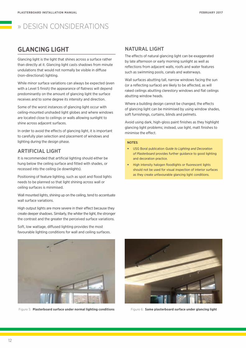
GLANCING LIGHTGlancing light is the light that shines across a surface rather than directly at it. Glancing light casts shadows from minute undulations that would not normally be visible in diffuse (non-directional) lighting.
While minor surface variations can always be expected (even with a Level 5 finish) the appearance of flatness will depend predominantly on the amount of glancing light the surface receives and to some degree its intensity and direction.
Some of the worst instances of glancing light occur with ceiling-mounted unshaded light globes and where windows are located close to ceilings or walls allowing sunlight to shine across adjacent surfaces.
In order to avoid the effects of glancing light, it is important to carefully plan selection and placement of windows and lighting during the design phase.
ARTIFICIAL LIGHTIt is recommended that artificial lighting should either be hung below the ceiling surface and fitted with shades, or recessed into the ceiling (ie downlights).
Positioning of feature lighting, such as spot and flood lights needs to be planned so that light shining across wall or ceiling surfaces is minimised.
Wall mounted lights, shining up on the ceiling, tend to accentuate wall surface variations.
High output lights are more severe in their effect because they create deeper shadows. Similarly, the whiter the light, the stronger the contrast and the greater the perceived surface variations.
Soft, low wattage, diffused lighting provides the most favourable lighting conditions for wall and ceiling surfaces.
NATURAL LIGHTThe effects of natural glancing light can be exaggerated by late afternoon or early morning sunlight as well as reflections from adjacent walls, roofs and water features such as swimming pools, canals and waterways.
Wall surfaces abutting tall, narrow windows facing the sun (or a reflecting surface) are likely to be affected, as will raked ceilings abutting clerestory windows and flat ceilings abutting window heads.
Where a building design cannot be changed, the effects of glancing light can be minimised by using window shades, soft furnishings, curtains, blinds and pelmets.
Avoid using dark, high-gloss paint finishes as they highlight glancing light problems; instead, use light, matt finishes to minimise the effect.
NOTES:
• USG Boral publication Guide to Lighting and Decoration of Plasterboard provides further guidance to good lighting and decoration practice.
• High intensity halogen floodlights or fluorescent lights should not be used for visual inspection of interior surfaces as they create unfavourable glancing light conditions.
Figure 6: Same plasterboard surface under glancing lightFigure 5: Plasterboard surface under normal lighting conditions
LINING MATERIALS
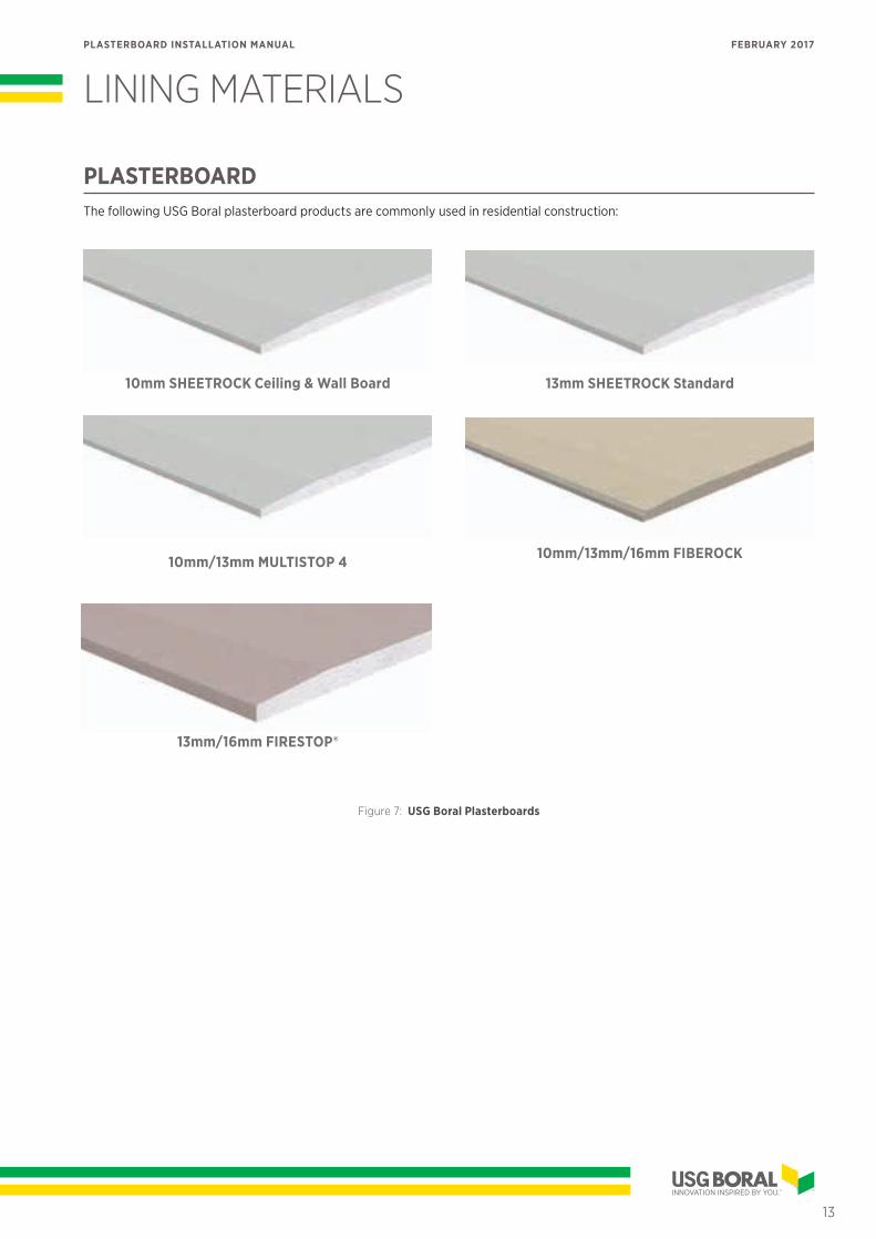
PLASTERBOARDThe following USG Boral plasterboard products are commonly used in residential construction:
10mm SHEETROCK Ceiling & Wall Board
10mm/13mm MULTISTOP 4
13mm SHEETROCK Standard
10mm/13mm/16mm FIBEROCK
Figure 7: USG Boral Plasterboards
13mm/16mm FIRESTOP®
13
PLASTERBOARD INSTALLATION MANUAL FEBRUARY 2017
» LINING MATERIALS
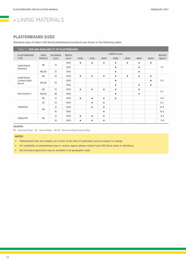
PLASTERBOARD SIZESStandard sizes of select USG Boral plasterboard products are shown in the following table:
TABLE 7: SIZE AND AVAILABILITY OF PLASTERBOARD
PLASTERBOARD TYPE
EDGE PROFILE
THICKNESS (mm)
WIDTH (mm)
LENGTH (mm) WEIGHT (kg/m2)2400 2700 3000 3600 4200 4800 6000
SHEETROCK Standard
RE 131200 • • • • • • •
7.21350 • •RE/SE 13 1350 • •
SHEETROCK Ceiling & Wall Board
RE 10 1200 • • • • • • •5.9
RE/SE 101200 • •1350 • • •
MULTISTOP 4
RE 10 1200 • • • • •9.7
RE/SE 10 1350 • •RE 13 1200 • • • • 11.8
FIBEROCK
SE 10 1200 • • 9.5
RE13 1200 • • 12.0
16 1200 • 15.0
FIRESTOP RE13 1200 • • • 8.2
16 1200 • • • 11.8
LEGEND:RE - Recessed Edge, SE - Square Edge, RE/SE - Recessed Edge/Square Edge
NOTES:
• Plasterboard sizes and weights are correct at the time of publication and are subject to change.
• For availability of plasterboard sizes in various regions please contact local USG Boral outlet or distributor.
• Not all board types/sizes may be available in all geographic areas
14
PLASTERBOARD INSTALLATION MANUAL FEBRUARY 2017
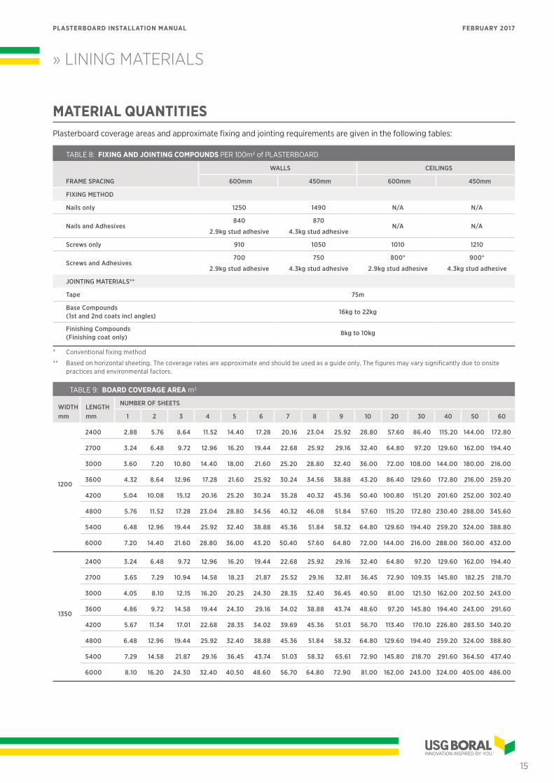
MATERIAL QUANTITIESPlasterboard coverage areas and approximate fixing and jointing requirements are given in the following tables:
TABLE 8: FIXING AND JOINTING COMPOUNDS PER 100m2 of PLASTERBOARD
FRAME SPACING
WALLS CEILINGS
600mm 450mm 600mm 450mm
FIXING METHOD
Nails only 1250 1490 N/A N/A
Nails and Adhesives840
2.9kg stud adhesive
870
4.3kg stud adhesiveN/A N/A
Screws only 910 1050 1010 1210
Screws and Adhesives700
2.9kg stud adhesive
750
4.3kg stud adhesive
800*
2.9kg stud adhesive
900*
4.3kg stud adhesive
JOINTING MATERIALS**
Tape 75m
Base Compounds (1st and 2nd coats incl angles)
16kg to 22kg
Finishing Compounds (Finishing coat only)
8kg to 10kg
» LINING MATERIALS
* Conventional fixing method
** Based on horizontal sheeting. The coverage rates are approximate and should be used as a guide only. The figures may vary significantly due to onsite practices and environmental factors.
TABLE 9: BOARD COVERAGE AREA m2
WIDTH mm
LENGTH mm
NUMBER OF SHEETS
1 2 3 4 5 6 7 8 9 10 20 30 40 50 60
1200
2400 2.88 5.76 8.64 11.52 14.40 17.28 20.16 23.04 25.92 28.80 57.60 86.40 115.20 144.00 172.80
2700 3.24 6.48 9.72 12.96 16.20 19.44 22.68 25.92 29.16 32.40 64.80 97.20 129.60 162.00 194.40
3000 3.60 7.20 10.80 14.40 18.00 21.60 25.20 28.80 32.40 36.00 72.00 108.00 144.00 180.00 216.00
3600 4.32 8.64 12.96 17.28 21.60 25.92 30.24 34.56 38.88 43.20 86.40 129.60 172.80 216.00 259.20
4200 5.04 10.08 15.12 20.16 25.20 30.24 35.28 40.32 45.36 50.40 100.80 151.20 201.60 252.00 302.40
4800 5.76 11.52 17.28 23.04 28.80 34.56 40.32 46.08 51.84 57.60 115.20 172.80 230.40 288.00 345.60
5400 6.48 12.96 19.44 25.92 32.40 38.88 45.36 51.84 58.32 64.80 129.60 194.40 259.20 324.00 388.80
6000 7.20 14.40 21.60 28.80 36.00 43.20 50.40 57.60 64.80 72.00 144.00 216.00 288.00 360.00 432.00
1350
2400 3.24 6.48 9.72 12.96 16.20 19.44 22.68 25.92 29.16 32.40 64.80 97.20 129.60 162.00 194.40
2700 3.65 7.29 10.94 14.58 18.23 21.87 25.52 29.16 32.81 36.45 72.90 109.35 145.80 182.25 218.70
3000 4.05 8.10 12.15 16.20 20.25 24.30 28.35 32.40 36.45 40.50 81.00 121.50 162.00 202.50 243.00
3600 4.86 9.72 14.58 19.44 24.30 29.16 34.02 38.88 43.74 48.60 97.20 145.80 194.40 243.00 291.60
4200 5.67 11.34 17.01 22.68 28.35 34.02 39.69 45.36 51.03 56.70 113.40 170.10 226.80 283.50 340.20
4800 6.48 12.96 19.44 25.92 32.40 38.88 45.36 51.84 58.32 64.80 129.60 194.40 259.20 324.00 388.80
5400 7.29 14.58 21.87 29.16 36.45 43.74 51.03 58.32 65.61 72.90 145.80 218.70 291.60 364.50 437.40
6000 8.10 16.20 24.30 32.40 40.50 48.60 56.70 64.80 72.90 81.00 162.00 243.00 324.00 405.00 486.00
15
PLASTERBOARD INSTALLATION MANUAL FEBRUARY 2017
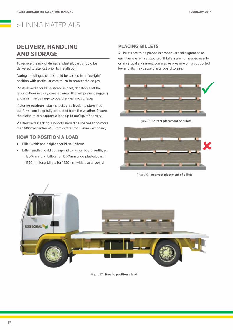
DELIVERY, HANDLING AND STORAGETo reduce the risk of damage, plasterboard should be delivered to site just prior to installation.
During handling, sheets should be carried in an ‘upright’ position with particular care taken to protect the edges.
Plasterboard should be stored in neat, flat stacks off the ground/floor in a dry covered area. This will prevent sagging and minimise damage to board edges and surfaces.
If storing outdoors, stack sheets on a level, moisture-free platform, and keep fully protected from the weather. Ensure the platform can support a load up to 800kg/m3 density.
Plasterboard stacking supports should be spaced at no more than 600mm centres (400mm centres for 6.5mm Flexiboard).
HOW TO POSITION A LOAD• Billet width and height should be uniform
• Billet length should correspond to plasterboard width, eg.
− 1200mm long billets for 1200mm wide plasterboard
− 1350mm long billets for 1350mm wide plasterboard.
PLACING BILLETSAll billets are to be placed in proper vertical alignment so each tier is evenly supported. If billets are not spaced evenly or in vertical alignment, cumulative pressure on unsupported lower units may cause plasterboard to sag.
Figure 8: Correct placement of billets
Figure 9: Incorrect placement of billets
» LINING MATERIALS
Figure 10: How to position a load
16
PLASTERBOARD INSTALLATION MANUAL FEBRUARY 2017
FRAMING CHECKPrior to installation of plasterboard, framing should be thoroughly checked by builder to ensure that:
• It is plumb, level and square.
• Spacing of studs, joists and battens does not exceed the limits specified in the relevant sections of this Manual.
• Maximum deviations in the bearing surface of the finished framing do not exceed the maximum tolerances allowed for the required Level of Finish (refer Table 6 Framing Tolerances). Where these tolerances are exceeded, a suitable levelling system should be used.
• Noggings supporting services such as taps and cisterns do not protrude beyond the face of the framing.
• All openings are framed and ceiling perimeter battens are installed where required.
• Trimmers are installed where primary ceiling support members such as girders, trusses and joists, change direction within a room or where required to support ceiling loads.
• All contact surfaces are dry, clean and free from foreign materials such as oil, grease and dirt.
• Plumbing and electrical services have been installed and do not protrude beyond the face of the framing.
• The area is weatherproof.
FIXING FACE REQUIREMENTSMinimum widths of framing member fixing faces are as follows:
TABLE 10: MINIMUM WIDTHS OF FIXING FACES (mm)
FIXING FACE TYPE TIMBER FRAMING STEEL FRAMING
Supporting a joint 35 32
Other 30 30
Plasterboard can be installed directly over existing linings
if they are firm, sound and sufficiently flat for the required
level of finish (ensure fasteners are of sufficient length by
allowing for the thickness of existing linings).
TIMBER FRAMINGTimber framing substrates for plasterboard linings must comply with the current NZS 3604, Timber Framed Buildings.
Roof trusses must comply with NZS3604 and AS/NZS 1170.
• Plasterboard is not to be installed to timber with a moisture content greater than 18% at the time of lining. Generally seasoned or kiln dried timbers such as Radiata Pine meet this criteria.
• Both mechanical fastener only or combination adhesive/fastener fixing methods can be used for low shrinkage timbers.
STEEL FRAMINGSteel framed plasterboard substrates must comply with AS/NZS 4600 Cold-formed steel structures, National Association of Steel-framed Housing (NASH) Standard for Residential and low-rise steel framing and AS 1397 Steel Sheet and Strip — hot dipped, zinc coated or aluminium/zinc coated.
The framing must be assembled and installed in accordance with the manufacturer’s instructions.
FRAMING
17
PLASTERBOARD INSTALLATION MANUAL FEBRUARY 2017
LININGS LAYOUT
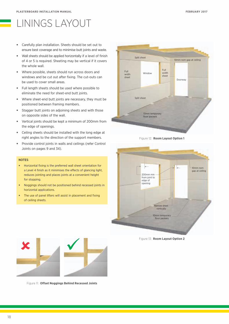
• Carefully plan installation. Sheets should be set out to ensure best coverage and to minimise butt joints and waste.
• Wall sheets should be applied horizontally if a level of finish of 4 or 5 is required. Sheeting may be vertical if it covers the whole wall.
• Where possible, sheets should run across doors and windows and be cut out after fixing. The cut-outs can be used to cover small areas.
• Full length sheets should be used where possible to eliminate the need for sheet-end butt joints.
• Where sheet-end butt joints are necessary, they must be positioned between framing members.
• Stagger butt joints on adjoining sheets and with those on opposite sides of the wall.
• Vertical joints should be kept a minimum of 200mm from the edge of openings.
• Ceiling sheets should be installed with the long edge at right angles to the direction of the support members.
• Provide control joints in walls and ceilings (refer Control Joints on pages 9 and 34).
NOTES:
• Horizontal fixing is the preferred wall sheet orientation for a Level 4 finish as it minimises the effects of glancing light, reduces jointing and places joints at a convenient height for stopping.
• Noggings should not be positioned behind recessed joints in horizontal applications.
• The use of panel lifters will assist in placement and fixing of ceiling sheets.
Figure 11: Offset Noggings Behind Recessed Joints
Doorway
Window
Split sheet
Split sheet
10mm nom gap at ceiling
Full width sheet
Full width sheet
10mm temporary floor packers
Figure 12: Room Layout Option 1
200mm min from joint to edge of opening
10mm nom gap at ceiling
10mm temporary floor packers
Narrow sheet vertically
Figure 13: Room Layout Option 2
18
PLASTERBOARD INSTALLATION MANUAL FEBRUARY 2017
PLASTERBOARD FIXING
Plasterboard should preferably be applied to ceilings first and then to walls. This will minimise sheet handling and damage.
FASTENING SYSTEMSPlasterboard should be fixed to framing using one of the following fastening systems:
• Combination of adhesive and fasteners
• Screw fixed only
• Nail fixed only.
NOTES:
• The combination adhesive and fastener system is the preferred option for general applications.
• Stud adhesive must comply with AS 2753.
• Use a fastener-only system on walls that are to be tiled or that may carry surface-mounted items such as mirrors — do not use adhesive.
• Fastener-only system must be used for fixing of FIBEROCK linings.
• Stud adhesive does not constitute a fixing system on its own and must be used in conjunction with screws or nails.
• Avoid fixing plasterboard linings before the installation of ridge capping and the enclosure of gable ends.
GENERAL SCREW AND NAIL FIXING• Plasterboard sheets must be held firm against framing
while driving fasteners.
• Fixing of the board to commence from centre out.
• Screws and nails should be slightly overdriven to allow for stopping but should not break the face paper.
• Screws and nails should be positioned 10–16mm from sheet edges and ends.
• Screws should be selected from Tables 11 and 12.
• Nails should be selected from Tables 13 and 14.
• Screws used for plasterboard fixing must comply with AS 3566 Self-drilling screws for the building and construction industries. Part 2: Corrosion resistance requirements.
PLASTERBOARD FASTENERS
SCREWS
* BMT - Base Metal Thickness
TABLE 11: PLASTERBOARD SCREWS
SCREW TYPE APPLICATION
W Wood/timber only
S Steel BMT* up to 0.75mm
D Steel BMT* 0.80 - 2.00mm
L Plasterboard laminating
TABLE 12: SCREW LENGTH (mm)
PLASTERBOARD LINING
TIMBER STEEL
WALLS CEILINGS WALLS CEILINGS
1x10mm 25 30 25 25
1x13mm 30 30 25 25
2x10mm 40 40 30 30
2x13mm 50 50 40 40
* Min 30mm W screws must be used for ceilings direct fixed to timber framing
NAILS
* USG Boral does not recommend nail fixing of ceiling linings
TABLE 13: PLASTERBOARD NAILS
NAIL TYPE APPLICATION*
Gold Passivated LH Smooth Shank Softwood Wall framing
Gold Passivated LH Ring Shank Softwood Wall framing
Galvanised LH Smooth Shank Hardwood Wall framing
Galvanised LH Ring Shank Softwood Wall framing
TABLE 14: NAIL LENGTH (mm)
PLASTERBOARD LINING
SMOOTH SHANKED NAILS
ANNULAR RING SHANKED NAILS
SOFTWOOD HARDWOOD SOFTWOOD HARDWOOD
1x10mm 40 30 30 -
1x13mm 40 30 30 -
2x10mm 50 50 - -
2x13mm 65 50 - -
19
PLASTERBOARD INSTALLATION MANUAL FEBRUARY 2017
INTERNAL CEILINGS
CEILING LOADS AND SPANSPlasterboard spans and loads directly supported on ceiling linings must not exceed the maximum values indicated in the following table:
TABLE 15: MAXIMUM LOADS AND SPANS FOR INTERNAL CEILINGS
PLASTERBOARD TYPE SPAN (mm)
MAXIMUM TOTAL LOAD* FOR GIVEN WIND CLASS (kg/m2)
LOW MEDIUM HIGH VERY HIGH
10mm SHEETROCK Ceiling & Wall Board
13mm SHEETROCK Standard
600 (max) 2.6** 2.6** 2.0 2.0
450 2.6**
10mm MULTISTOP 4 450 (max) 2.0
* Total Load includes weight of insulation and any fixtures directly supported on ceiling linings.
** 1/3 Fixing method must be used if directly supported load exceeds 2.0kg/m2 (maximum load 2.6kg/m2).
NOTES:
• Loads in excess of the above must be supported independently from a roof or ceiling structure.
• Roof / ceiling framing must be checked for its capacity to carry supported loads.
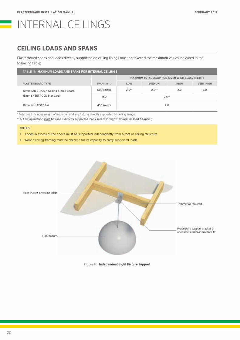
Proprietary support bracket of adequate load bearing capacity
Light fixture
Roof trusses or ceiling joists
Trimmer as required
Figure 14: Independent Light Fixture Support
20
PLASTERBOARD INSTALLATION MANUAL FEBRUARY 2017
» INTERNAL CEILINGS
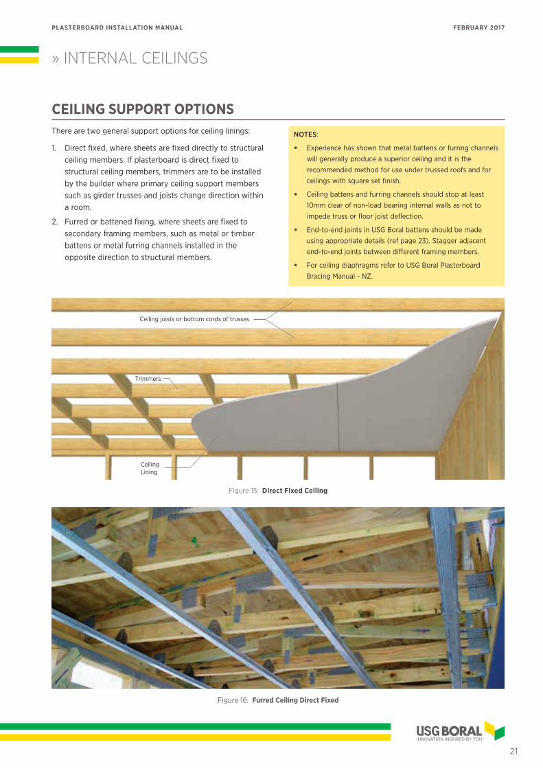
CEILING SUPPORT OPTIONSThere are two general support options for ceiling linings:
1. Direct fixed, where sheets are fixed directly to structural ceiling members. If plasterboard is direct fixed to structural ceiling members, trimmers are to be installed by the builder where primary ceiling support members such as girder trusses and joists change direction within a room.
2. Furred or battened fixing, where sheets are fixed to secondary framing members, such as metal or timber battens or metal furring channels installed in the opposite direction to structural members.
NOTES:
• Experience has shown that metal battens or furring channels will generally produce a superior ceiling and it is the recommended method for use under trussed roofs and for ceilings with square set finish.
• Ceiling battens and furring channels should stop at least 10mm clear of non-load bearing internal walls as not to impede truss or floor joist deflection.
• End-to-end joints in USG Boral battens should be made using appropriate details (ref page 23). Stagger adjacent end-to-end joints between different framing members.
• For ceiling diaphragms refer to USG Boral Plasterboard Bracing Manual - NZ.
Figure 15: Direct Fixed Ceiling
Figure 16: Furred Ceiling Direct Fixed
Trimmers
CeilingLining
Ceiling joists or bottom cords of trusses
21
PLASTERBOARD INSTALLATION MANUAL FEBRUARY 2017
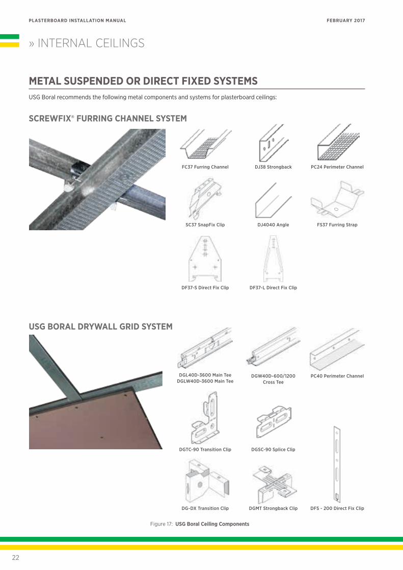
» INTERNAL CEILINGS
Figure 17: USG Boral Ceiling Components
METAL SUSPENDED OR DIRECT FIXED SYSTEMSUSG Boral recommends the following metal components and systems for plasterboard ceilings:
DGSC-90 Splice Clip
DFS - 200 Direct Fix ClipDG-DX Transition Clip DGMT Strongback Clip
DGTC-90 Transition Clip
SCREWFIX® FURRING CHANNEL SYSTEM
USG BORAL DRYWALL GRID SYSTEM
FC37 Furring Channel
SC37 SnapFix Clip
DF37-S Direct Fix Clip
DJ38 Strongback
DGW40D-600/1200 Cross Tee
DJ4040 Angle
DF37-L Direct Fix Clip
PC24 Perimeter Channel
PC40 Perimeter Channel
FS37 Furring Strap
DGL40D-3600 Main Tee DGLW40D-3600 Main Tee
22
PLASTERBOARD INSTALLATION MANUAL FEBRUARY 2017
» INTERNAL CEILINGS
CONTROL JOINTSRefer Control Joints on page 9 for guidance on control joint
locations and construction.
FIXING TO CEILINGS
FIXING WITH COMBINATION OF ADHESIVE AND SCREW FASTENERS
General Fixing Notes• Framing members should be clean and free from dust,
dirt, grease and surface moisture.
• Refer to General Screw and Nail Fixing on page 19.
• Stud adhesive must comply with AS 2753.
• Stud adhesive daubs should be approx 25mm diameter x 15mm high.
• Do not use adhesive at sheet ends.
• Keep daubs 200mm (nom) from sheet edges.
• Keep daubs 200mm (nom) from screw points.
• It is recommended that at sheet ends screws are spaced at 300mm maximum centres for cornices and 150mm maximum centres for square set finish.
200mm nom
FramingPlasterboard lining
Adhesive daub W-type
screw fastener
Figure 18: Adhesives and screw fasteners at sheet edges
ADHESIVE AND FASTENER LAYOUT
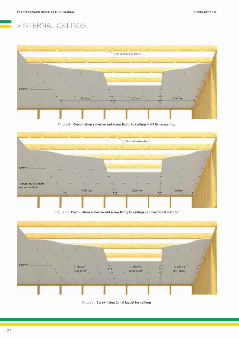
1/3 Fixing Method (Preferred)Space fasteners at 1/3 points across the width of the sheet
and daubs half way between fasteners.
Conventional Method (non-braced linings)Use single screws (or double fasteners 50-75mm apart) along the sheet centreline and space daubs between the fasteners at 230mm maximum centres.
Ceiling fastener and adhesive layouts for both methods are shown in the table below.
TABLE 20: ADHESIVE AND FASTENER LAYOUT FOR CEILINGS
SHEET WIDTH CONVENTIONAL FIXING 1/3 FIXING
900mm FAF/FAF FAFAF
1200mm FAAF/FAAF FAFAFAF
1350mm FAAF/FAAF FAFAFAF
Legend: F = screw A = adhesive
NOTES:
• USG Boral plasterboard has lines printed on the face of the sheet to guide fixing.
• When using conventional method, temporary fasteners (nails or screws driven through plasterboard blocks to hold sheets in place while adhesive cures) should be installed at every second framing member and remain for at least 24 hours.
FIXING WITH SCREWS ONLY• Space screws at maximum 300mm centres across
the width of the sheet.
• At sheet ends space screws at 300mm maximum centres for cornices and 150mm maximum centres for square set finish.
• Refer to General Screw and Nail Fixing on page 19.
• Refer Table 21 and Figure 21 for the number of screwing points across the sheet width.
• Fiberock linings must be fixed with screws only.
TABLE 21: SCREW FIXING (ONLY) LAYOUT FOR CEILINGS
SHEET WIDTH SCREW POINTS
900mm 4
1200mm 5
1350mm 6
Note: Screw points should be equally spaced
23
PLASTERBOARD INSTALLATION MANUAL FEBRUARY 2017
» INTERNAL CEILINGS
Figure 21: Screw fixing (only) layout for ceilings
Figure 19: Combination adhesive and screw fixing to ceilings – 1/3 fixing method
Figure 20: Combination adhesive and screw fixing to ceilings - conventional method
1350mm 1200mm 900mm
Screws
Stud adhesive daubs
Temporary fasteners recommended
Screws
1350mm 1200mm 900mm
Stud adhesive daubs
6 screws1350 sheet
5 screws1200 sheet
4 screws900 sheet
Screws
24
PLASTERBOARD INSTALLATION MANUAL FEBRUARY 2017
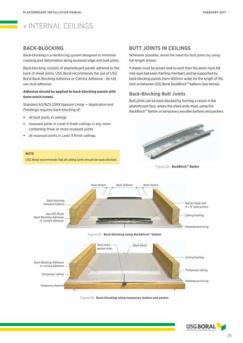
BACK-BLOCKINGBack-blocking is a reinforcing system designed to minimise cracking and deformation along recessed edge and butt joints.
Back-blocking consists of plasterboard panels adhered to the back of sheet joints. USG Boral recommends the use of USG Boral Back-Blocking Adhesive or Cornice Adhesive - do not use stud adhesive.
Adhesive should be applied to back-blocking panels with 6mm notch trowel.
Standard AS/NZS 2589 Gypsum Lining — Application and Finishings requires back-blocking of:
• all butt joints in ceilings
• recessed joints in Level 4 finish ceilings in any room containing three or more recessed joints
• all recessed joints in Level 5 finish ceilings.
NOTE:
USG Boral recommends that all ceiling joints should be back-blocked.
» INTERNAL CEILINGS
BUTT JOINTS IN CEILINGSWherever possible, avoid the need for butt joints by using full length sheets.
If sheets must be joined ‘end-to-end’ then the joints must fall mid-span between framing members and be supported by back-blocking panels (nom 400mm wide) for the length of the joint or between USG Boral BackBlock™ battens (see below).
Back-Blocking Butt JointsButt joints can be back-blocked by forming a recess in the plasterboard face, where the sheet ends meet, using the BackBlock™ Batten or temporary wooden battens and packers.
Figure 22: BackBlock™ Batten
Batten fixed with 4 x 'S' type screws
Use USG Boral Back-Blocking Adhesive
or cornice adhesive
Back-blockingbetween battens
Nom 50mm Nom 50mmNom 300mm
Plasterboard lining
Ceiling framing
Figure 23: Back-blocking using BackBlock™ batten
Plasterboard lining
Back-block
Ceiling framing
Temporary nailingTemporary nailing
Temporary battens
USG BoralBack-Blocking Adhesive
or cornice adhesive
3mm thick packer strip
Figure 24: Back-blocking using temporary batten and packer
25
PLASTERBOARD INSTALLATION MANUAL FEBRUARY 2017
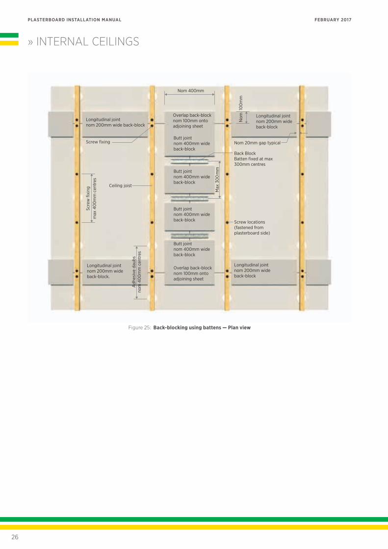
Longitudinal joint nom 200mm wide back-block
Overlap back-block nom 100mm onto adjoining sheet
Butt joint nom 400mm wide back-block
Butt joint nom 400mm wide back-block
Butt joint nom 400mm wide back-block
Butt joint nom 400mm wide back-block
Overlap back-block nom 100mm onto adjoining sheet
Longitudinal joint nom 200mm wide back-block
Back Block Batten fixed at max 300mm centres
Nom 20mm gap typical
Screw locations (fastened from plasterboard side)
Longitudinal joint nom 200mm wide back-block
Longitudinal joint nom 200mm wide back-block.
Screw fixing
Ceiling joist
Max
30
0m
m
Nom
10
0m
m
Scre
w fi
max
40
0m
m c
entr
es
Adh
esiv
e da
ubs
nom
40
0m
m c
entr
es
Nom 400mm
Figure 25: Back-blocking using battens — Plan view
» INTERNAL CEILINGS
26
PLASTERBOARD INSTALLATION MANUAL FEBRUARY 2017
GARAGE AND EXTERNAL CEILINGS
GENERALCeilings in garages, carports, verandahs and alfresco areas are subject to more extreme loads and conditions than normal internal ceilings and require special attention to their fixing and detailing.
Some factors contributing to these extra loads include:
• Wind loads
• Condensation
• Roller door vibrations
• Insufficient perimeter support
• Exposure to atmospheric variations (ie humidity, temperature, etc).
NOTES:
• External ceilings left unpainted for prolonged periods of time should be covered with a sealer coat to reduce the risk of board and compound deterioration.
• All Purpose compounds are not recommended for external applications.
• Consideration should be given to the use of plastic external angles in highly corrosive environments.
DESIGN NOTES• The following USG Boral products are recommended
for lining of garage ceilings, alfresco areas and other external protected ceilings:
− 10mm SHEETROCK Ceiling Board
− 13mm SHEETROCK Standard
− 10mm MULTISTOP™ 4
− 13mm MULTISTOP™ 4
− 13mm FIBEROCK.
• Refer to Table 22 for maximum frame and screw spacings for external ceilings.
• Provide foil sarking and good ventilation to prevent heat build up and condensation pooling on the top
of plasterboard.
• Provide a min 6mm wide gap between the edges of ceiling linings and adjacent walls, beams, columns and fascias.
• Fascia boards and perimeter beams should extend a min 25mm below plasterboard to provide a drip edge.
• Screws used for fixing of external ceiling linings must comply with AS 3566 Self-drilling screws for the building and construction industries. Part 2: Corrosion resistance requirements.
27
PLASTERBOARD INSTALLATION MANUAL FEBRUARY 2017
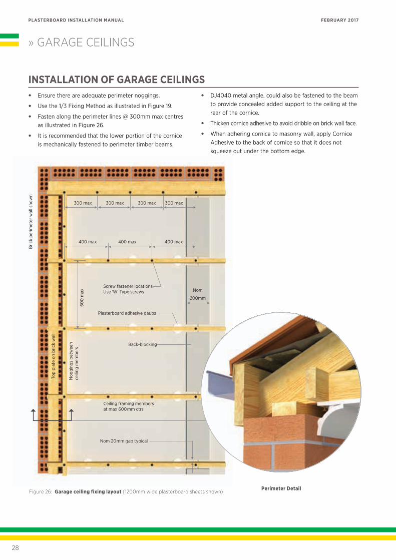
INSTALLATION OF GARAGE CEILINGS• Ensure there are adequate perimeter noggings.
• Use the 1/3 Fixing Method as illustrated in Figure 19.
• Fasten along the perimeter lines @ 300mm max centres as illustrated in Figure 26.
• It is recommended that the lower portion of the cornice is mechanically fastened to perimeter timber beams.
• DJ4040 metal angle, could also be fastened to the beam to provide concealed added support to the ceiling at the rear of the cornice.
• Thicken cornice adhesive to avoid dribble on brick wall face.
• When adhering cornice to masonry wall, apply Cornice Adhesive to the back of cornice so that it does not squeeze out under the bottom edge.
» GARAGE CEILINGSB
rick
perim
eter
wal
l sho
wn
300 max 300 max 300 max 300 max
400 max 400 max 400 max
Screw fastener locations.Use ‘W’ Type screws
Plasterboard adhesive daubs
Back-blocking
Nom
200mm
Top
plat
e on
bric
k w
all
600
max
Nog
ging
s be
twee
n
ceili
ng m
embe
rs
Ceiling framing members at max 600mm ctrs
Nom 20mm gap typical
Figure 26: Garage ceiling fixing layout (1200mm wide plasterboard sheets shown)Perimeter Detail
28
PLASTERBOARD INSTALLATION MANUAL FEBRUARY 2017
» EXTERNAL CEILINGS
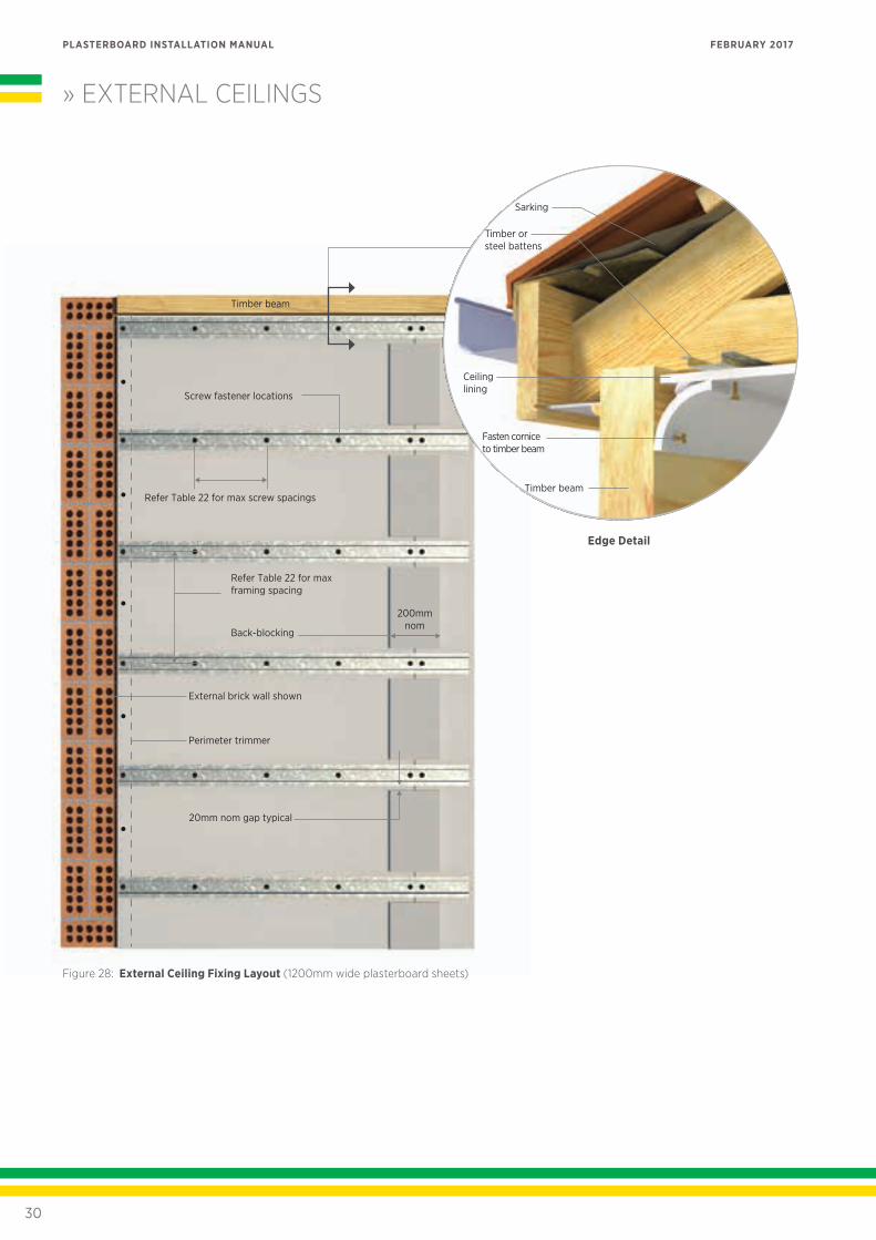
INSTALLATION OF EXTERNAL CEILINGS• Spacing between framing members should not exceed
the maximum values indicated in Table 22. In areas where these values are exceeded, suitable ceiling battens or furring channels should be provided at required spacings. Metal ceiling battens and furring channels should be installed in accordance with USG Boral specifications.
• Ceiling linings should be fully screw fixed at maximum spacings indicated in Table 22. Refer Table 11 and 12 for screw types.
• At sheet ends space screws at 300mm maximum centres for cornices and 150mm maximum centres for square set finish.
• Run plasterboard sheets at right angles to framing members.
• Back-block all joints in ceiling linings as per USG Boral back-blocking specifications.
• Control joints must be provided in external ceilings at max 6m centres in both directions.
• External ceilings should be painted with a three coat exterior paint system including a sealer undercoat and applied in accordance with manufacturer’s recommendations.
TABLE 22: MAXIMUM FRAMING AND FIXING SPACINGS FOR EXTERNAL CEILINGS
CEILING LINING
WIND CLASS
LOW MEDIUM HIGH VERY HIGH
10mm SHEETROCK Ceiling Board
13mm SHEETROCK Standard
10mm MULTISTOP 4
13mm MULTISTOP 4
13mm FIBEROCK
Max Framing Spacing (mm)
450 450 300 300
Max Screw Spacing (mm)
300 300 250 200
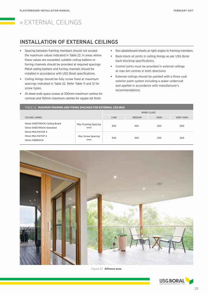
Figure 27: Alfresco area
29
PLASTERBOARD INSTALLATION MANUAL FEBRUARY 2017
» EXTERNAL CEILINGS
20mm nom gap typical
Screw fastener locations
Refer Table 22 for max screw spacings
External brick wall shown
Perimeter trimmer
Back-blocking
Timber beam
200mm nom
Refer Table 22 for max framing spacing
Figure 28: External Ceiling Fixing Layout (1200mm wide plasterboard sheets)
Edge Detail
Ceiling lining
Timber beam
Timber or steel battens
Fasten cornice to timber beam
Sarking
30
PLASTERBOARD INSTALLATION MANUAL FEBRUARY 2017
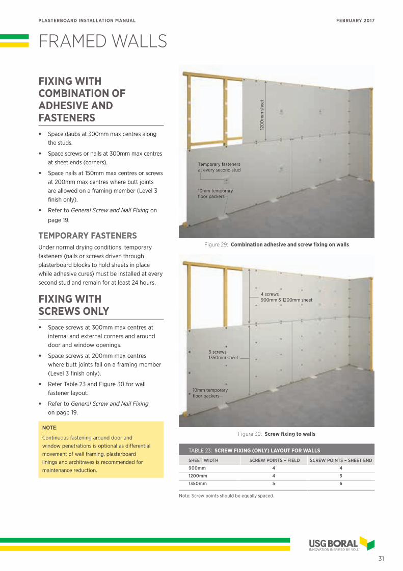
FRAMED WALLS
FIXING WITH COMBINATION OF ADHESIVE AND FASTENERS• Space daubs at 300mm max centres along
the studs.
• Space screws or nails at 300mm max centres at sheet ends (corners).
• Space nails at 150mm max centres or screws at 200mm max centres where butt joints are allowed on a framing member (Level 3 finish only).
• Refer to General Screw and Nail Fixing on
page 19.
TEMPORARY FASTENERSUnder normal drying conditions, temporary fasteners (nails or screws driven through plasterboard blocks to hold sheets in place while adhesive cures) must be installed at every second stud and remain for at least 24 hours.
FIXING WITH SCREWS ONLY• Space screws at 300mm max centres at
internal and external corners and around door and window openings.
• Space screws at 200mm max centres where butt joints fall on a framing member (Level 3 finish only).
• Refer Table 23 and Figure 30 for wall fastener layout.
• Refer to General Screw and Nail Fixing on page 19.
NOTE:
Continuous fastening around door and window penetrations is optional as differential movement of wall framing, plasterboard linings and architraves is recommended for maintenance reduction.
120
0m
m s
heet
Temporary fasteners at every second stud
10mm temporary floor packers
Figure 29: Combination adhesive and screw fixing on walls
4 screws900mm & 1200mm sheet
5 screws1350mm sheet
10mm temporary floor packers
Figure 30: Screw fixing to walls
TABLE 23: SCREW FIXING (ONLY) LAYOUT FOR WALLS
SHEET WIDTH SCREW POINTS – FIELD SCREW POINTS – SHEET END
900mm 4 4
1200mm 4 5
1350mm 5 6
Note: Screw points should be equally spaced.
31
PLASTERBOARD INSTALLATION MANUAL FEBRUARY 2017
» FRAMED WALLS
FIXING WITH NAILS ONLY (Level 3 finish only)• Space single nails at 240mm max centres in
the field and at sheet ends (corners).
• Space double nails at 400mm max centres in the field and at 300mm max centres at
sheet ends (corners).
• Space nails at 150mm max centres where butt joints are allowed on a framing member (Level 3 finish only).
• Double nails should be 50–75mm apart.
• Refer Table 24 and Figure 31 for min number of nailing points per framing member.
• Refer to General Screw and Nail Fixing on page 19.
BUTT JOINTS IN WALLSWherever possible, avoid the need for butt joints by using full length plasterboard sheets.
If sheets must be joined ‘end-to-end’, the joints should fall within 50mm of the mid-span between framing members. Butt joints greater than 400mm in length and less than 2m above floor must be back-blocked with nom 400mm wide back-blocking panels for the length of the joint. Butt joints on opposite sides of the wall should fall between different framing members.
NOTE:
Butt joints in walls may be made on a framing member only if Level 3 finish is required.
1350mm sheet7 nails
5 nails – 900mm sheet6 nails – 1200mm sheet
Figure 31: Nail fixing to walls (single nails)
TABLE 24: NAIL FIXING (ONLY) LAYOUT FOR WALLS
SINGLE NAILS
SHEET WIDTH NAIL POINTS IN FIELD NAIL POINTS AT SHEET END
900mm 5 5
1200mm 6 6
1350mm 7 7
DOUBLE NAILS
SHEET WIDTH NAIL POINTS IN FIELD NAIL POINTS AT SHEET END
900mm 4 4
1200mm 4 5
1350mm 5 6
Note: Nail points should be equally spaced.
32
PLASTERBOARD INSTALLATION MANUAL FEBRUARY 2017
» FRAMED WALLS
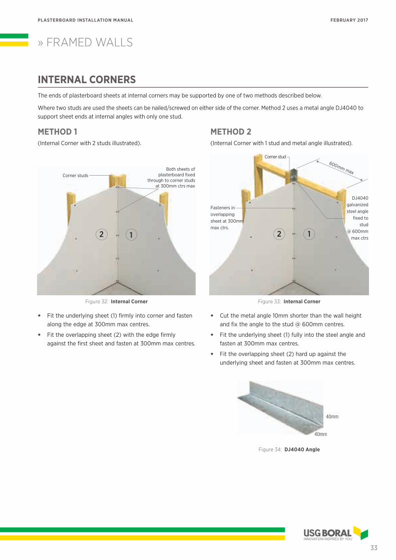
INTERNAL CORNERSThe ends of plasterboard sheets at internal corners may be supported by one of two methods described below.
Where two studs are used the sheets can be nailed/screwed on either side of the corner. Method 2 uses a metal angle DJ4040 to support sheet ends at internal angles with only one stud.
METHOD 1(Internal Corner with 2 studs illustrated).
Corner studs
12
Both sheets of plasterboard fixed
through to corner studs at 300mm ctrs max
Figure 32: Internal Corner
• Fit the underlying sheet (1) firmly into corner and fasten along the edge at 300mm max centres.
• Fit the overlapping sheet (2) with the edge firmly against the first sheet and fasten at 300mm max centres.
METHOD 2(Internal Corner with 1 stud and metal angle illustrated).
600mm max
DJ4040galvanizedsteel angle
fixed to stud
@ 600mmmax ctrs
Fasteners in overlapping sheet at 300mm max ctrs.
Corner stud
12
Figure 33: Internal Corner
• Cut the metal angle 10mm shorter than the wall height and fix the angle to the stud @ 600mm centres.
• Fit the underlying sheet (1) fully into the steel angle and fasten at 300mm max centres.
• Fit the overlapping sheet (2) hard up against the underlying sheet and fasten at 300mm max centres.
40mm
40mm
Figure 34: DJ4040 Angle
33
PLASTERBOARD INSTALLATION MANUAL FEBRUARY 2017
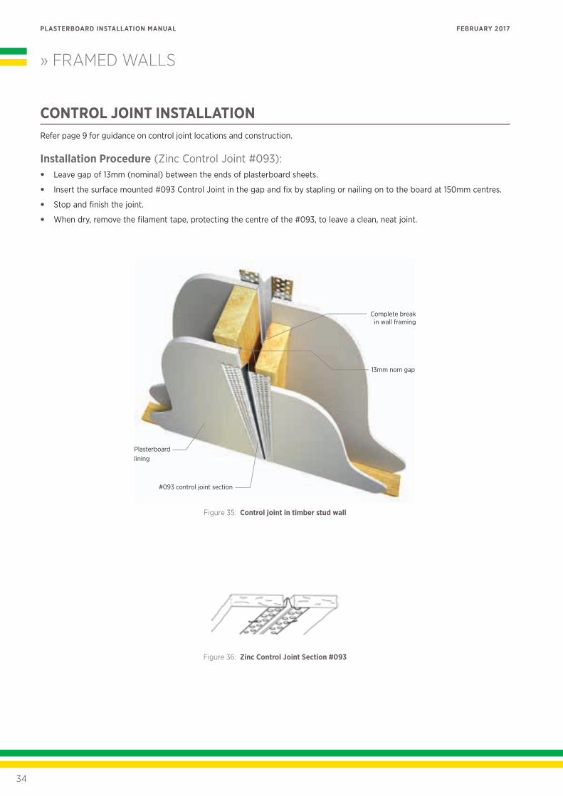
CONTROL JOINT INSTALLATIONRefer page 9 for guidance on control joint locations and construction.
Installation Procedure (Zinc Control Joint #093):• Leave gap of 13mm (nominal) between the ends of plasterboard sheets.
• Insert the surface mounted #093 Control Joint in the gap and fix by stapling or nailing on to the board at 150mm centres.
• Stop and finish the joint.
• When dry, remove the filament tape, protecting the centre of the #093, to leave a clean, neat joint.
» FRAMED WALLS
13mm nom gap
Figure 35: Control joint in timber stud wall
Zinc Control Joint #093Zinc Control Joint #093
Figure 36: Zinc Control Joint Section #093
34
PLASTERBOARD INSTALLATION MANUAL FEBRUARY 2017
» FRAMED WALLS
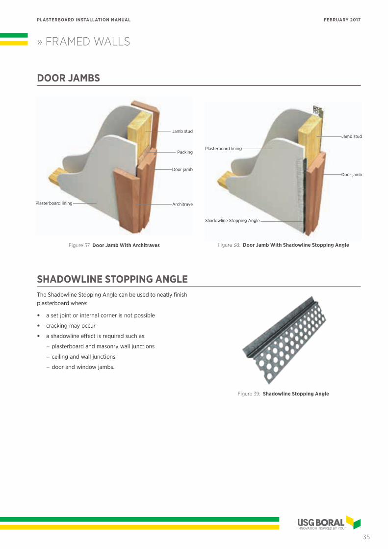
DOOR JAMBS
Door jamb
Architrave
Packing
Jamb stud
Plasterboard lining
Figure 37 Door Jamb With Architraves
Door jamb
Jamb stud
Shadowline Stopping Angle
Plasterboard lining
Figure 38: Door Jamb With Shadowline Stopping Angle
SHADOWLINE STOPPING ANGLEThe Shadowline Stopping Angle can be used to neatly finish plasterboard where:
• a set joint or internal corner is not possible
• cracking may occur
• a shadowline effect is required such as:
− plasterboard and masonry wall junctions
− ceiling and wall junctions
− door and window jambs.
Figure 39: Shadowline Stopping Angle
35
PLASTERBOARD INSTALLATION MANUAL FEBRUARY 2017
Wall lining
Ceiling lining
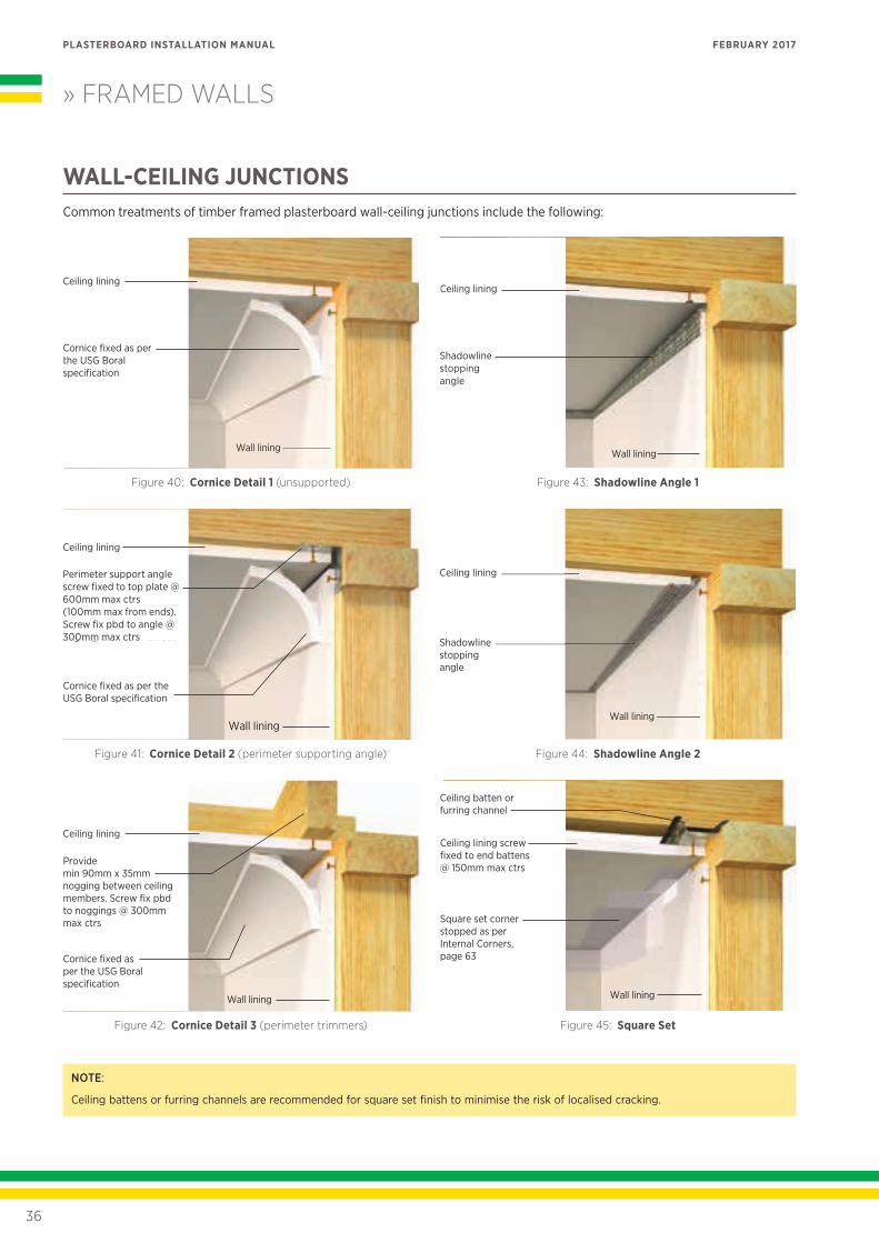
Cornice fixed as per the USG Boral specification
Figure 40: Cornice Detail 1 (unsupported)
Wall lining
Ceiling lining
Cornice fixed as per the USG Boral specification
Rondo P40 perimeter support angle screw fixed to top plate @ 600mm max ctrs (100mm max from ends). Screw fix pbd to angle @ 300mm max ctrs
Figure 41: Cornice Detail 2 (perimeter supporting angle)
Wall lining
Ceiling lining
Cornice fixed as per the USG Boral specification
Provide min 90mm x 35mm nogging between ceiling members. Screw fix pbd to noggings @ 300mm max ctrs
Figure 42: Cornice Detail 3 (perimeter trimmers)
Wall lining
Rondo P50shadowline stopping angle
Ceiling lining
Figure 43: Shadowline Angle 1
Wall lining
Shadowline stopping angle
Ceiling lining
Figure 44: Shadowline Angle 2
Wall lining
Square set corner stopped as per Internal Corners, page 63
Ceiling lining screw fixed to end battens @ 150mm max ctrs
Ceiling batten or furring channel
Figure 45: Square Set
» FRAMED WALLS
WALL-CEILING JUNCTIONSCommon treatments of timber framed plasterboard wall-ceiling junctions include the following:
NOTE:
Ceiling battens or furring channels are recommended for square set finish to minimise the risk of localised cracking.
Shadowline stopping angle
Perimeter support angle screw fixed to top plate @ 600mm max ctrs (100mm max from ends). Screw fix pbd to angle @ 300mm max ctrs
36
PLASTERBOARD INSTALLATION MANUAL FEBRUARY 2017
MASONRY WALLS
GENERALUSG Boral plasterboard provides a dry alternative to cement render and solid plaster finishes over masonry walls.
Two common installation methods are:
• Fixing sheets directly to masonry using USG Boral Masonry Adhesive
• Fixing sheets over timber battens or metal furring channels fastened to masonry.
The batten/furring channel method will allow a cavity space for services to run between the masonry wall and plasterboard as well as providing a true fixing surface and air flow ventilation.
It is essential that all new masonry surfaces be allowed to dry to in-service levels before installing USG Boral plasterboards.
Masonry walls in wet areas, such as bathrooms and laundries must be lined with WETSTOP or FIBEROCK as per the wet area installation requirements (refer page 40).
NOTE:
Linings in tiled and wet areas must be mechanically fastened to furring channels or timber battens.
Masonry walls should be checked for flatness and level using a straight edge or string line before
determining the fixing method.
Masonry adhesive method should not be used for walls over 3m high or where the wall surface requires more than 25mm of packing to bring it back to a true line.
All services should be in place prior to plasterboard installation. Butt joints, control joints, jointing and finishing should be as per standard practice.
INSTALLATION USING MASONRY ADHESIVE METHODMasonry walls must be dry and free from dust, oil, flaking paint, efflorescence, release agents, or any other material or treatment that could adversely affect bonding of masonry adhesive.
Adhesion can also be affected by the porosity and/or previous surface treatment of a wall. Surfaces that are particularly dry or porous may need to be dampened. For best results masonry walls should be coated with a bonding agent before applying masonry adhesive.
NOTE:
It is important that plasterboard sheets for masonry applications are stacked flat as misaligned boards can hinder bonding process.
Masonry adhesive may be applied either to a wall or to the back of a sheet. (If gluing plasterboard to Autoclaved Aerated Concrete – AAC – then masonry adhesive should only be applied to the back of the sheet).
It is important to:
• Mix only enough masonry adhesive as can be used before it starts to set.
• Do not use masonry adhesive once it has started to set.
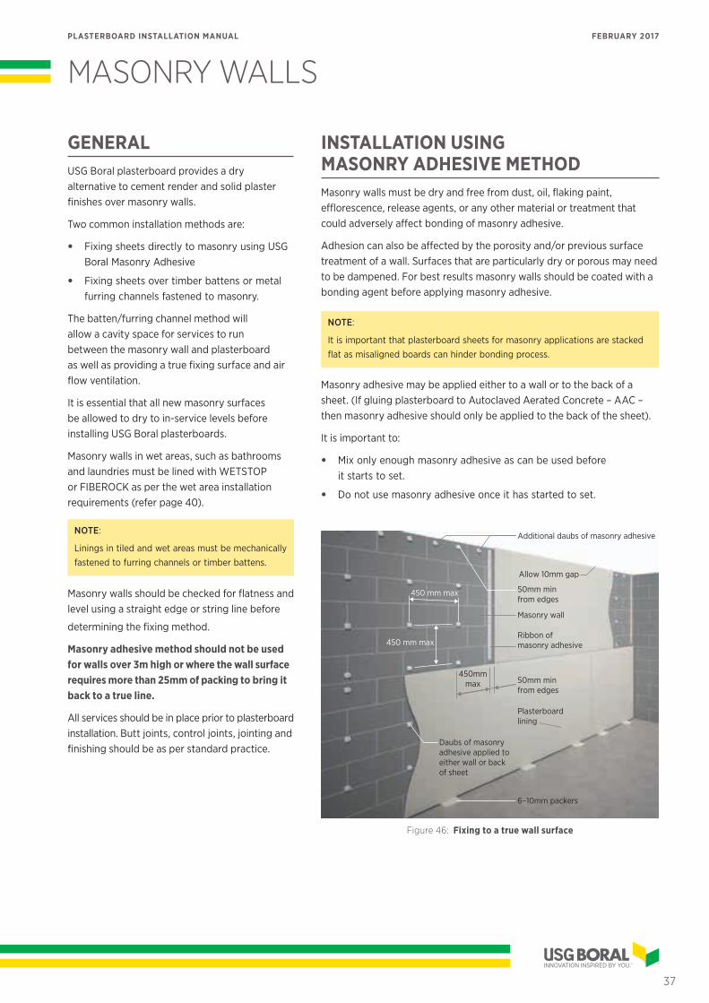
Additional daubs of masonry adhesive
Masonry wall
6–10mm packers
50mm min from edges
450mm max 50mm min
from edges
Allow 10mm gap
Ribbon of masonry adhesive450 mm max
450 mm max
Plasterboard lining
Daubs of masonry adhesive applied to either wall or back of sheet
Figure 46: Fixing to a true wall surface
37
PLASTERBOARD INSTALLATION MANUAL FEBRUARY 2017
MASONRY ADHESIVE METHOD INSTALLATION NOTES• Strike chalk lines on the floor and ceiling as a guide for
positioning sheets. Allow for board and daub thicknesses.
• Mark lines on the wall to assist in positioning the masonry adhesive daubs.
• Masonry adhesive daubs should be about 50mm diameter by 15mm thickness.
• Space adhesive daubs at maximum 450mm centres vertically and horizontally and 50mm from free edges and ends of sheets.
• Ribbons or additional daubs of masonry adhesive must be applied at sheet ends and at cornice and skirting lines. Additional daubs of masonry adhesive are also required at external angles, fixtures and around services penetrations, doors and windows.
• Alternatively, a ‘solid wall’ effect can be achieved by applying cornice or masonry adhesive to the entire back face of the sheets, using a 15mm x 15mm notched trowel.
• Keep sheets 6–10mm off the floor.
• Place plasterboard and press firmly into position using a long straight edge to level the sheets vertically and horizontally.
• Hold the sheets in position with props or temporary fasteners until masonry adhesive sets.
• Once initial contact has been made, boards should not be pulled back from the wall.
• Once installed, boards should not be disturbed for 48 hours (ie no drumming or rattling of walls, cutting of light switches or power points).
• Avoid skinning of masonry adhesive in windy weather.
• Avoid early removal of bottom packers.
NOTE:
All fixtures must be fastened directly into masonry wall.
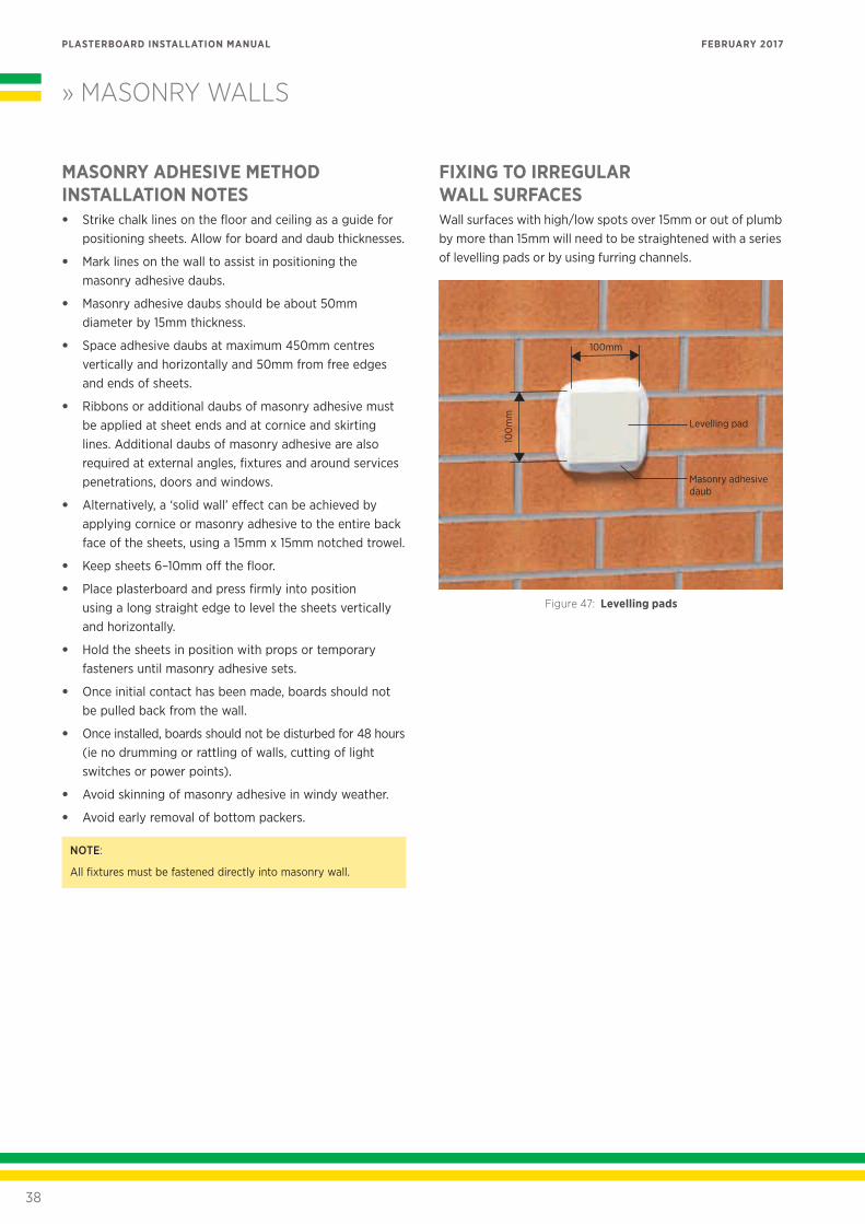
FIXING TO IRREGULAR WALL SURFACESWall surfaces with high/low spots over 15mm or out of plumb by more than 15mm will need to be straightened with a series of levelling pads or by using furring channels.
100
mm
100mm
Masonry adhesive daub
Levelling pad
Figure 47: Levelling pads
» MASONRY WALLS
38
PLASTERBOARD INSTALLATION MANUAL FEBRUARY 2017
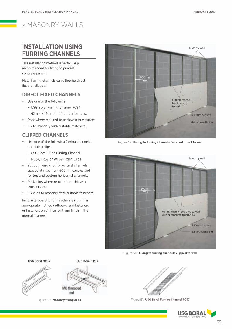
» MASONRY WALLS
INSTALLATION USING FURRING CHANNELSThis installation method is particularly recommended for fixing to precast concrete panels.
Metal furring channels can either be direct fixed or clipped:
DIRECT FIXED CHANNELS• Use one of the following:
− USG Boral Furring Channel FC37
− 42mm x 19mm (min) timber battens.
• Pack where required to achieve a true surface.
• Fix to masonry with suitable fasteners.
CLIPPED CHANNELS• Use one of the following furring channels
and fixing clips:
− USG Boral FC37 Furring Channel
− MC37, TR37 or WF37 Fixing Clips
• Set out fixing clips for vertical channels spaced at maximum 600mm centres and for top and bottom horizontal channels.
• Pack clips where required to achieve a true surface.
• Fix clips to masonry with suitable fasteners.
Fix plasterboard to furring channels using an appropriate method (adhesive and fasteners or fasteners only) then joint and finish in the normal manner.
Masonry wall
6-10mm packers
Plasterboard lining
Furring channel fixed directly to wall
600mm max
Figure 49: Fixing to furring channels fastened direct to wall
6-10mm packers
Plasterboard lining
Furring channel attached to wall with appropriate fixing clips
600mm max
Masonry wall
Figure 50: Fixing to furring channels clipped to wall
Figure 48: Masonry fixing clips Figure 51: USG Boral Furring Channel FC37
USG Boral MC37 USG Boral TR37
39
PLASTERBOARD INSTALLATION MANUAL FEBRUARY 2017
WET AREAS
40
PLASTERBOARD INSTALLATION MANUAL FEBRUARY 2017
REGULATORY REQUIREMENTS
DEFINITION AND STANDARDSMinimum waterproofing and water-resistance requirements for walls in wet areas are outlined in NZBC CLAUSE E3/AS1 and are summarised in Table 26 and Figures 53 to 58.
E3/AS1 and AS/NZS 4858 set out minimum material, design and installation requirements for waterproofing of wet areas within residential buildings and other buildings with similar usage intensity. It also outlines typical wet area construction materials and methods.
Water-resistant plasterboard manufactured to AS/NZS 2588 Gypsum Plasterboard constitutes a water resistant substrate for tiles or other nominated water resistant surface materials.
Waterproofing membranes used in wet areas must comply with AS/NZS 4858 Wet Area Membranes.
WATERPROOFING OF WET AREASWhere wall to wall junction is required to be waterproof, waterproofing must extent a min 40mm either side of the junction.
For water resistant plasterboard sheeting all cut edges that have the potential to be affected by moisture must be waterproofed, including the bottom edge over a preformed shower base.
All penetrations through wall linings in shower areas (including penetrations of mechanical fasteners) must be waterproofed.
NOTE:
USG Boral Wet Area system requires waterproofing of all
plasterboard joints in wet areas unless a waterproofing
membrane complying with AS/NZS 4858 Wet area membranes
or a Codemark approved product is applied by a specialist
contractor over the whole face of wet area walls.
WATERPROOFING MEMBRANESWaterproofing membranes complying with AS/NZS 4858 Wet Area Membranes are deemed to be a waterproof material when used as part of a waterproofing system as outlined in E3/AS1.
Bond breaker must be installed at all wall/floor, hob/wall junctions and at movement joints where the waterproofing membrane is bonded to substrate. Bond breaker must be compatible with the flexibility of waterproofing membrane.
Types of waterproofing membranes and corresponding bond breaker widths are shown in the following table:
TABLE 25: WATERPROOFING MEMBRANES
MEMBRANE CLASS EXTENSIBILITY
ELONGATION AT BREAK
MIN BOND BREAKER WIDTH TO BRIDGE JOINTS OPENING
UP TO 5mm
I Low 10-59%75mm tape with
backing rod
II Medium 60-299% 35mm
III High = > 300% 12mm
CEILINGS OVER WET AREASAs NZBC does not require the use of water resistant ceiling linings over wet areas, SHEETROCK® Brand plasterboard provides an adequate solution for this application. FIBEROCK®, or MULTISTOP™ 4 can be used in wet area ceilings if water resistant linings are desirable.
Ceiling linings over wet areas in residential buildings can be fixed as per the standard internal ceiling installation specification (refer to page 21).
Fiberock® gypsum board must be fixed using screws only fixing method.
NOTE:
USG Boral recommends that ceiling paint in wet areas should be impervious to moisture.
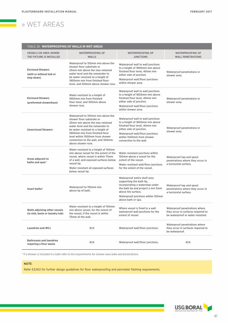
» WET AREAS
41
PLASTERBOARD INSTALLATION MANUAL FEBRUARY 2017
TABLE 26: WATERPROOFING OF WALLS IN WET AREAS
VESSELS OR AREA WHERE THE FIXTURE IS INSTALLED
WATERPROOFING OF WALLS
WATERPROOFING OF JUNCTIONS
WATERPROOFING OF WALL PENETRATIONS
Enclosed Showers
(with or without hob or step down)
Waterproof to 150mm min above the shower floor substrate or 25mm min above the max retained water level and the remainder to be water resistant to a height of 1800mm min from finished floor level, and 300mm above shower rose.
Waterproof wall to wall junctions to a height of 1800mm min above finished floor level, 40mm min either side of junction.
Waterproof wall/floor junctions within shower area.
Waterproof penetrations in shower area.
Enclosed Showers
(preformed showerbase)
Water resistant to a height of 1800mm min from finished floor level, and 300mm above shower rose.
Waterproof wall to wall junctions to a height of 1800mm min above finished floor level, 40mm min either side of junction.
Waterproof wall/floor junctions within shower area.
Waterproof penetrations in shower area.
Unenclosed Showers
Waterproof to 150mm min above the shower floor substrate or 25mm min above the max retained water level and the remainder to be water resistant to a height of 1800mm min from finished floor level within 1500mm from shower connection to the wall, and 300mm above shower rose.
Waterproof wall to wall junctions to a height of 1800mm min above finished floor level, 40mm min either side of junction.
Waterproof wall/floor junctions within 1500mm from shower connection to the wall.
Waterproof penetrations in shower area.
Areas adjacent to baths and spas*
Water resistant to a height of 150mm min above vessel for the extent of the vessel, where vessel is within 75mm of a wall, and exposed surfaces below vessel lip.
Water resistant all exposed surfaces below vessel lip.
Water resistant junctions within 150mm above a vessel for the extent of the vessel.
Water resistant wall/floor junctions for the extent of the vessel.
Waterproof tap and spout penetrations where they occur in a horizontal surface.
Insert baths*Waterproof to 150mm min above lip of bath.
Waterproof entire shelf area supporting the bath lip, incorporating a waterstop under the bath lip and project a min 5mm above tile surface.
Waterproof junctions within 150mm above bath or spa.
Waterproof tap and spout penetrations where they occur in a horizontal surface.
Walls adjoining other vessels (ie sink, basin or laundry tub)
Water resistant to a height of 150mm min above vessel, for the extent of the vessel, if the vessel is within 75mm of the wall.
Where vessel is fixed to a wall waterproof wall junctions for the extent of vessel.
Waterproof penetrations where they occur in surfaces required to be waterproof or water resistant.
Laundries and WCs N/A Waterproof wall/floor junctions.Waterproof penetrations where they occur in surfaces required to be waterproof.
Bathrooms and laundries requiring a floor waste
N/A Waterproof wall/floor junctions. N/A
* If a shower is included in a bath refer to the requirements for shower area walls and penetrations.
NOTE:
Refer E3/AS1 for further design guidelines for floor waterproofing and perimeter flashing requirements.
» WET AREAS
42
PLASTERBOARD INSTALLATION MANUAL FEBRUARY 2017
USG BORAL WET AREAUSG Boral Wet Area comprises materials and installation details outlined in this manual and must be installed in accordance with USG Boral specification to achieve the required performance.
USG Boral Wet Area complies with the requirements of E3/AS1 and is thus suitable for use in residential buildings and other buildings with a similar usage pattern.
USG Boral Wet Area is not suitable for use in high exposure applications such as group shower rooms, steam rooms, etc.
WET AREA MATERIALS
MULTISTOP™ 4USG Boral MULTISTOP™ 4 is manufactured with a moisture resistant core that stops water wicking up the board causing damage to the board itself or to surface finish.
MULTISTOP™ 4 is manufactured with recessed edges for flush jointing within and outside of tiled areas.
MULTISTOP™ 4 complies with water resistance requirements of AS 3740.
MULTISTOP™ 4 is available in 10mm and 13mm thicknesses.
FIBEROCK®FIBEROCK® is a water resistant paperless gypsum board offering additional benefits of mold resistance and high impact resistance. FIBEROCK® contains 95% recycled materials.
FIBEROCK® can be used as an alternative wall lining in USG Boral Wet Area and can be installed using the same fixing, jointing and waterproofing materials and details as specified for MULTISTOP™ 4.
13mm and 16mm are manufactured with recessed edges for flush jointing.
10mm is manufactured in square edges and is suitable where flush jointing is not required eg. under tiles.
WET AREA SEALANTA wet area sealant is a flexible acrylic sealant suitable for waterproofing:
• Wall junctions and cutouts
• Bottom of sheets in shower bases or bath abutments
• Around plumbing fixtures and penetrations.
The selected wet area sealant must comply with requirements of E3/AS1 for waterproof materials.
CORNER SUPPORT ANGLE40mm x 40mm galvanised metal angle USG Boral DJ4040 is used to support internal corners in wet areas.
PREPARATION OF WET AREASCheck framing for layout and fixing of additional noggings to support wet area fittings such as screens and taps and the continuous support for USG Boral water resistant linings at the shower base and bath rims.
Provide adequate noggings 25mm (nominal) above bath, shower bases, tubs and sinks for fixing the edges of USG Boral water resistant linings.
Ensure that plumbing pipes and noggings do not protrude beyond the face of the studs.
Recess preformed shower bases and baths into studs so that USG Boral water resistant linings can sit correctly in front of the shower base upstand. This will provide a natural flashing point.
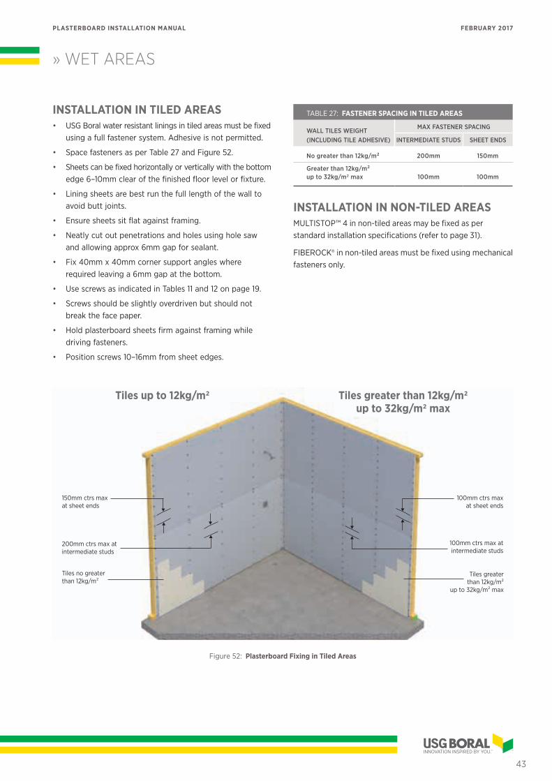
» WET AREAS
43
PLASTERBOARD INSTALLATION MANUAL FEBRUARY 2017
Tiles no greater than 12kg/m2
200mm ctrs max at intermediate studs
150mm ctrs max at sheet ends
100mm ctrs max at intermediate studs
100mm ctrs max at sheet ends
Tiles greater than 12kg/m2
up to 32kg/m2 max
INSTALLATION IN TILED AREAS • USG Boral water resistant linings in tiled areas must be fixed
using a full fastener system. Adhesive is not permitted.
• Space fasteners as per Table 27 and Figure 52.
• Sheets can be fixed horizontally or vertically with the bottom edge 6–10mm clear of the finished floor level or fixture.
• Lining sheets are best run the full length of the wall to avoid butt joints.
• Ensure sheets sit flat against framing.
• Neatly cut out penetrations and holes using hole saw and allowing approx 6mm gap for sealant.
• Fix 40mm x 40mm corner support angles where required leaving a 6mm gap at the bottom.
• Use screws as indicated in Tables 11 and 12 on page 19.
• Screws should be slightly overdriven but should not break the face paper.
• Hold plasterboard sheets firm against framing while driving fasteners.
• Position screws 10–16mm from sheet edges.
Tiles up to 12kg/m2 Tiles greater than 12kg/m2 up to 32kg/m2 max
TABLE 27: FASTENER SPACING IN TILED AREAS
WALL TILES WEIGHT (INCLUDING TILE ADHESIVE)
MAX FASTENER SPACING
INTERMEDIATE STUDS SHEET ENDS
No greater than 12kg/m2 200mm 150mm
Greater than 12kg/m2 up to 32kg/m2 max 100mm 100mm
INSTALLATION IN NON-TILED AREASMULTISTOP™ 4 in non-tiled areas may be fixed as per standard installation specifications (refer to page 31).
FIBEROCK® in non-tiled areas must be fixed using mechanical fasteners only.
Figure 52: Plasterboard Fixing in Tiled Areas
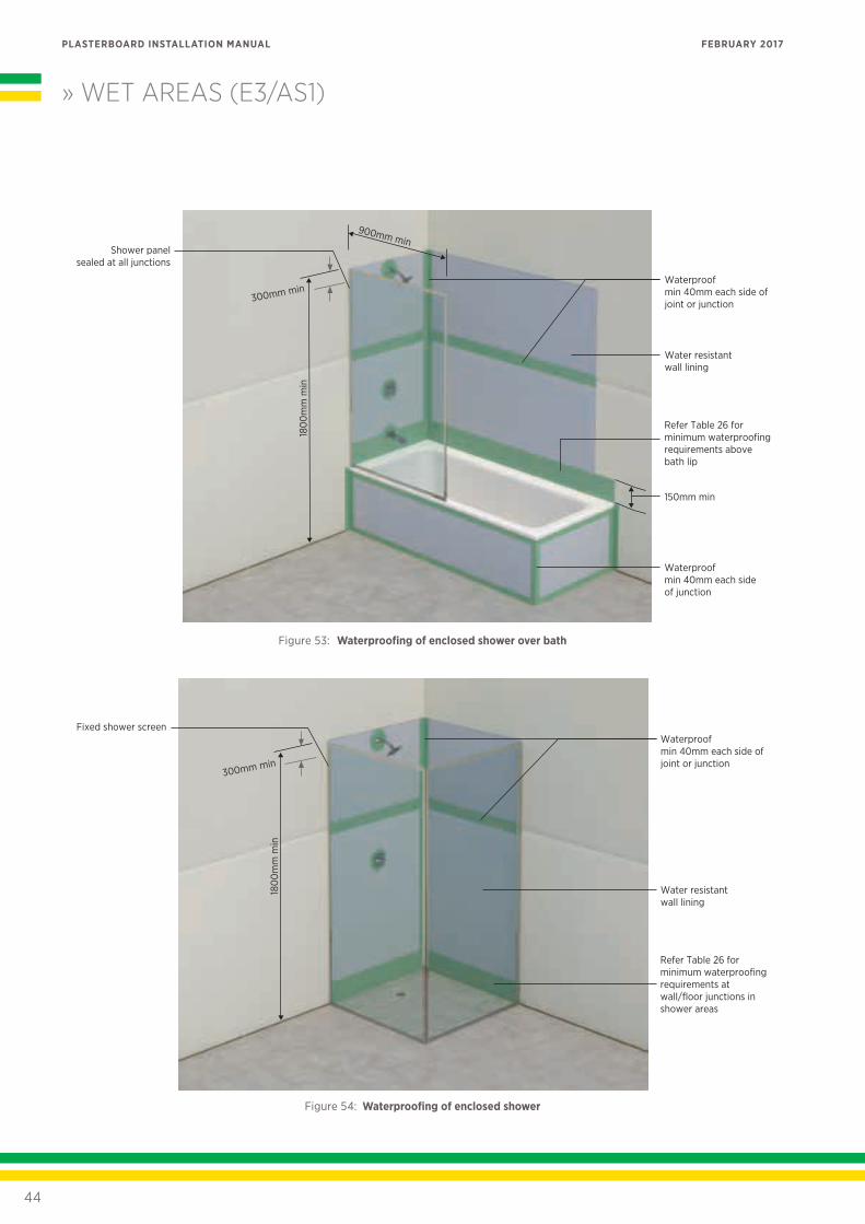
» WET AREAS (E3/AS1)
44
PLASTERBOARD INSTALLATION MANUAL FEBRUARY 2017
Figure 53: Waterproofing of enclosed shower over bath
Figure 54: Waterproofing of enclosed shower
Shower panel sealed at all junctions
Waterproof min 40mm each side of joint or junction
Waterproof min 40mm each side of junction
Water resistant wall lining
Refer Table 26 for minimum waterproofing requirements above bath lip
180
0m
m m
in
900mm min
150mm min
180
0m
m m
in
Fixed shower screenWaterproof min 40mm each side of joint or junction
Water resistant wall lining
Refer Table 26 for minimum waterproofing requirements at wall/floor junctions in shower areas
300mm min
300mm min
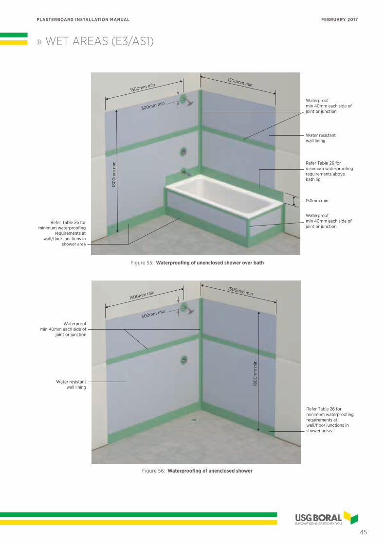
» WET AREAS (E3/AS1)
45
PLASTERBOARD INSTALLATION MANUAL FEBRUARY 2017
Figure 55: Waterproofing of unenclosed shower over bath
Figure 56: Waterproofing of unenclosed shower
1500mm min1500mm min
150mm min
180
0m
m m
in
Waterproof min 40mm each side of joint or junction
Waterproof min 40mm each side of joint or junction
Water resistant wall lining
Refer Table 26 for minimum waterproofing requirements above bath lip
Refer Table 26 for minimum waterproofing
requirements at wall/floor junctions in
shower area
180
0m
m m
in
1500mm min1500mm min
Waterproof min 40mm each side of
joint or junction
Water resistant wall lining
Refer Table 26 for minimum waterproofing requirements at wall/floor junctions in shower areas
300mm min
300mm min
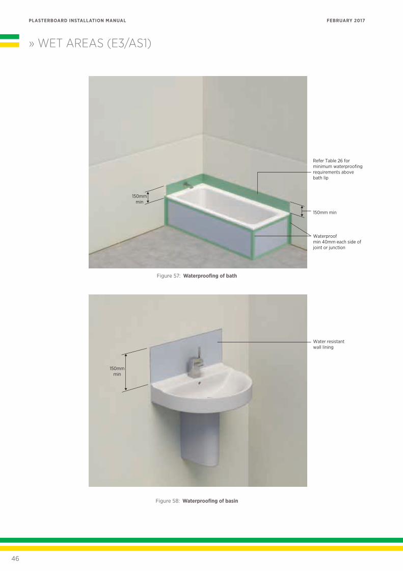
» WET AREAS (E3/AS1)
46
PLASTERBOARD INSTALLATION MANUAL FEBRUARY 2017
Figure 57: Waterproofing of bath
Figure 58: Waterproofing of basin
150mmmin
150mm min
Waterproof min 40mm each side of joint or junction
Refer Table 26 for minimum waterproofing requirements above bath lip
150mmmin
Water resistant wall lining
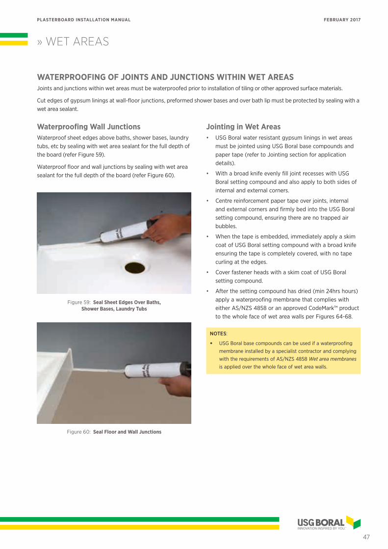
» WET AREAS
47
PLASTERBOARD INSTALLATION MANUAL FEBRUARY 2017
WATERPROOFING OF JOINTS AND JUNCTIONS WITHIN WET AREASJoints and junctions within wet areas must be waterproofed prior to installation of tiling or other approved surface materials.
Cut edges of gypsum linings at wall-floor junctions, preformed shower bases and over bath lip must be protected by sealing with a wet area sealant.
Waterproofing Wall JunctionsWaterproof sheet edges above baths, shower bases, laundry tubs, etc by sealing with wet area sealant for the full depth of the board (refer Figure 59).
Waterproof floor and wall junctions by sealing with wet area sealant for the full depth of the board (refer Figure 60).
Figure 59: Seal Sheet Edges Over Baths, Shower Bases, Laundry Tubs
Figure 60: Seal Floor and Wall Junctions
Jointing in Wet Areas • USG Boral water resistant gypsum linings in wet areas
must be jointed using USG Boral base compounds and paper tape (refer to Jointing section for application details).
• With a broad knife evenly fill joint recesses with USG Boral setting compound and also apply to both sides of internal and external corners.
• Centre reinforcement paper tape over joints, internal and external corners and firmly bed into the USG Boral setting compound, ensuring there are no trapped air bubbles.
• When the tape is embedded, immediately apply a skim coat of USG Boral setting compound with a broad knife ensuring the tape is completely covered, with no tape curling at the edges.
• Cover fastener heads with a skim coat of USG Boral setting compound.
• After the setting compound has dried (min 24hrs hours) apply a waterproofing membrane that complies with either AS/NZS 4858 or an approved CodeMark™ product to the whole face of wet area walls per Figures 64-68.
NOTES:
• USG Boral base compounds can be used if a waterproofing membrane installed by a specialist contractor and complying with the requirements of AS/NZS 4858 Wet area membranes is applied over the whole face of wet area walls.
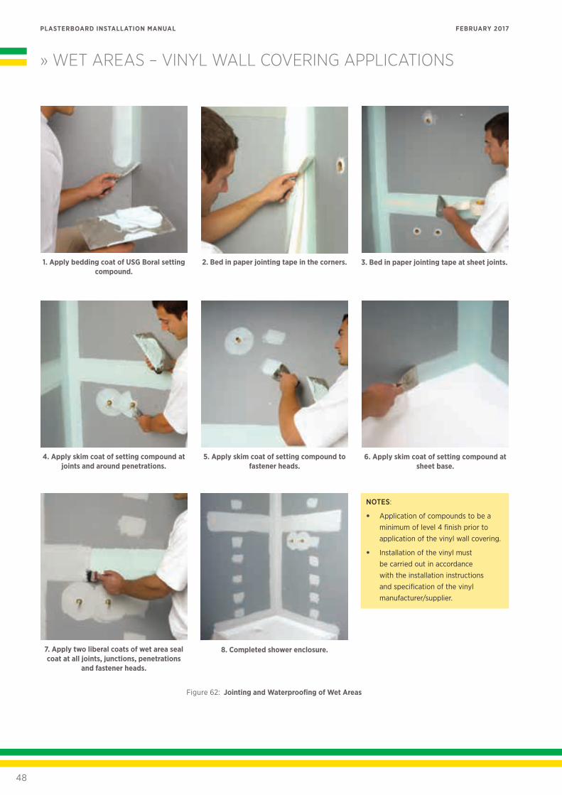
» WET AREAS – VINYL WALL COVERING APPLICATIONS
48
PLASTERBOARD INSTALLATION MANUAL FEBRUARY 2017
5. Apply skim coat of setting compound to fastener heads.
6. Apply skim coat of setting compound at sheet base.
3. Bed in paper jointing tape at sheet joints.
4. Apply skim coat of setting compound at joints and around penetrations.
2. Bed in paper jointing tape in the corners.1. Apply bedding coat of USG Boral setting compound.
7. Apply two liberal coats of wet area seal coat at all joints, junctions, penetrations
and fastener heads.
8. Completed shower enclosure.
Figure 62: Jointing and Waterproofing of Wet Areas
NOTES:
• Application of compounds to be a minimum of level 4 finish prior to application of the vinyl wall covering.
• Installation of the vinyl must be carried out in accordance with the installation instructions and specification of the vinyl manufacturer/supplier.
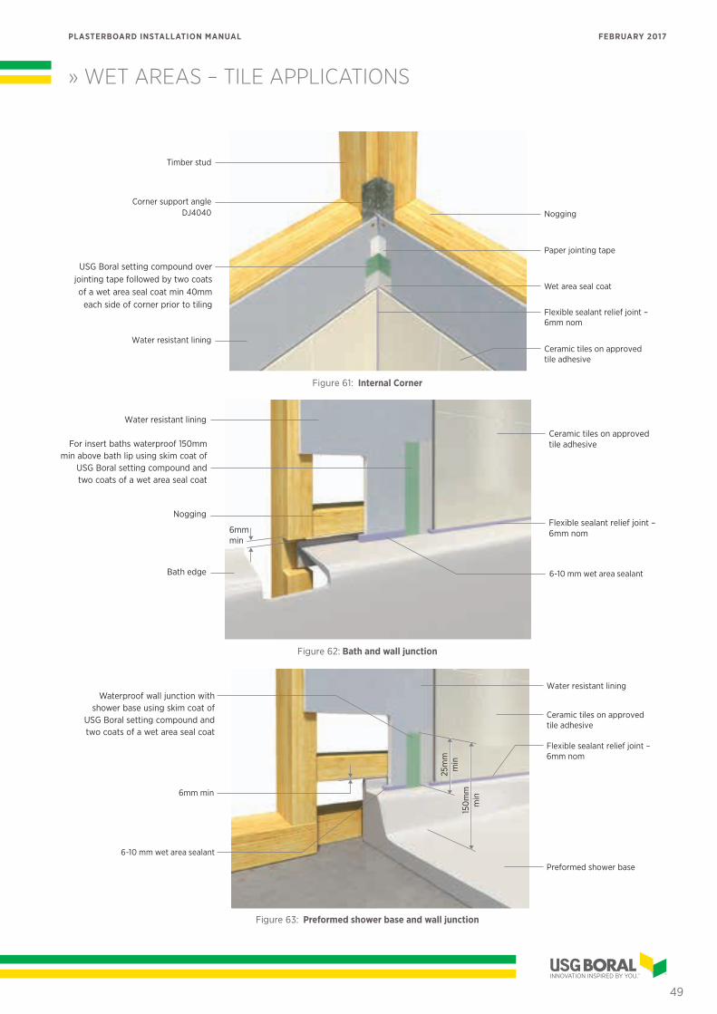
» WET AREAS – TILE APPLICATIONS
49
PLASTERBOARD INSTALLATION MANUAL FEBRUARY 2017
Ceramic tiles on approved tile adhesive
Wet Area SealCote
Flexible sealant relief joint – 6mm nom
Paper jointing tape
Nogging
Wet Area Taping Cement over jointing tape followed by two coats
of USG Boral Wet Area SealCote min 40mm each side of corner
prior to tiling
Water resistant lining
Corner support angle
Timber stud
Figure 61: Internal Corner
For insert baths waterproof 150mm min above bath lip using skim coat
of Wet Area Taping Cement and two coats of Wet Area SealCote
Water resistant lining
Nogging
Bath edge
Ceramic tiles on approved tile adhesive
6–10mm Wet Area Sealant
Flexible sealant relief joint – 6mm nom6mm
min
Figure 62: Bath and wall junction
25m
mm
in15
0m
mm
in
Preformed shower base
6mm min
Ceramic tiles on approved tile adhesive
6-10mm USG Boral Wet Area Sealant
Waterproof wall junction with shower base using skim coat of
Wet Area Taping Cement and two coats of Wet Area Sealcote
Flexible sealant relief joint – 6mm nom
Water resistant lining
Figure 63: Preformed shower base and wall junction
6-10 mm wet area sealant
6-10 mm wet area sealant
USG Boral setting compound over jointing tape followed by two coats of a wet area seal coat min 40mm
each side of corner prior to tiling
DJ4040
For insert baths waterproof 150mm min above bath lip using skim coat of
USG Boral setting compound and two coats of a wet area seal coat
Waterproof wall junction with shower base using skim coat of
USG Boral setting compound and two coats of a wet area seal coat
Wet area seal coat
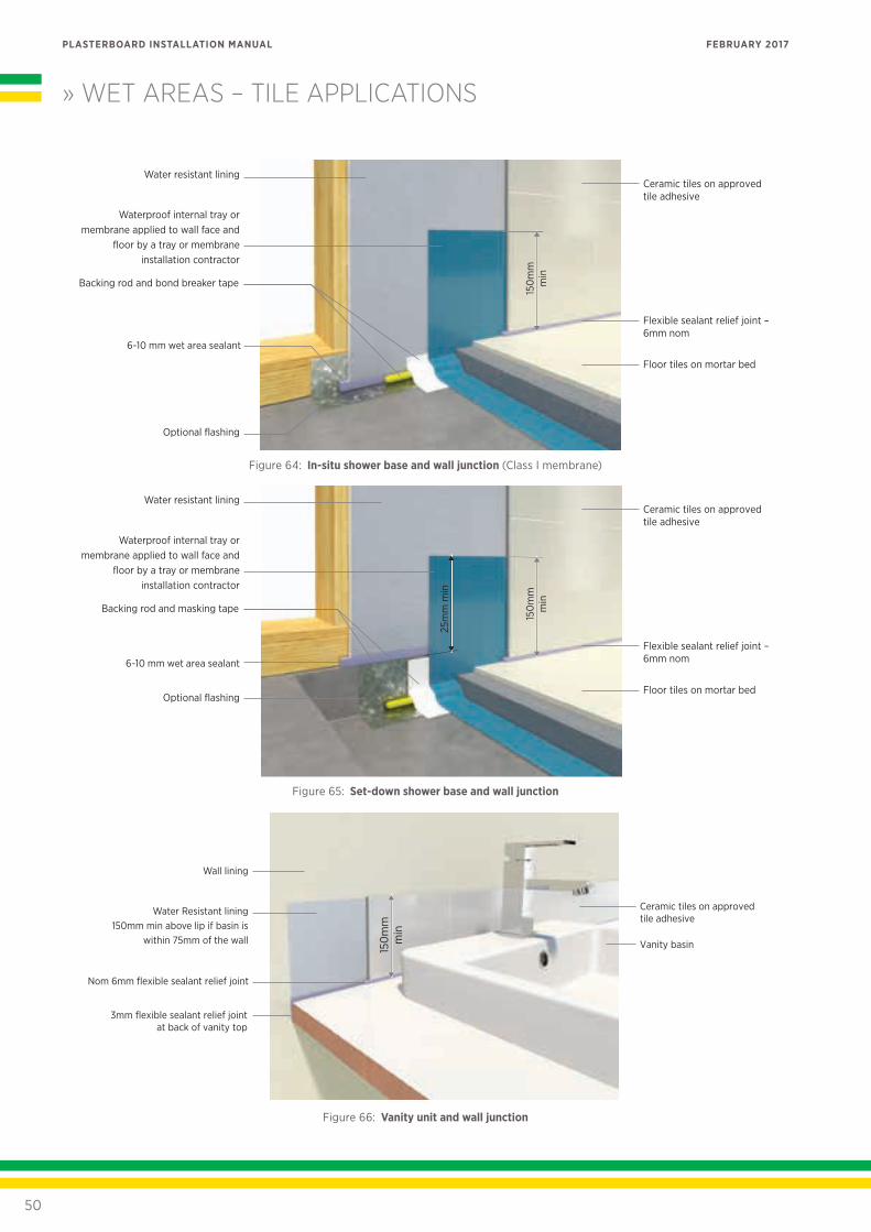
» WET AREAS – TILE APPLICATIONS
50
PLASTERBOARD INSTALLATION MANUAL FEBRUARY 2017
Floor tiles on mortar bed
Backing rod and bond breaker tape
Optional flashing
Water resistant lining
Waterproof internal tray or membrane applied to wall face and
floor by a tray or membrane installation contractor
Ceramic tiles on approved tile adhesive
6-10mm USG Boral Wet Area Sealant
Flexible sealant relief joint – 6mm nom
150
mm
min
Figure 64: In-situ shower base and wall junction (Class I membrane)
Floor tiles on mortar bed
Backing rod and masking tape
Optional flashing
Water resistant lining
Waterproof internal tray or membrane applied to wall face and
floor by a tray or membrane installation contractor
Ceramic tiles on approved tile adhesive
6-10mm USG Boral Wet Area Sealant
Flexible sealant relief joint – 6mm nom
150
mm
min
25m
m m
in
Figure 65: Set-down shower base and wall junction
Ceramic tiles on approved tile adhesive
Vanity basin
Nom 6mm flexible sealant relief joint
Water Resistant lining150mm min above lip if basin is
within 75mm of the wall
South Australia:3mm flexible sealant relief joint
at back of vanity top
Wall lining
150
mm
min
Figure 66: Vanity unit and wall junction
6-10 mm wet area sealant
6-10 mm wet area sealant
Ceramic tiles on approved tile adhesive
Vanity basin
Nom 6mm flexible sealant relief joint
Water Resistant lining150mm min above lip if basin is
within 75mm of the wall
South Australia:3mm flexible sealant relief joint
at back of vanity top
Wall lining
150
mm
min
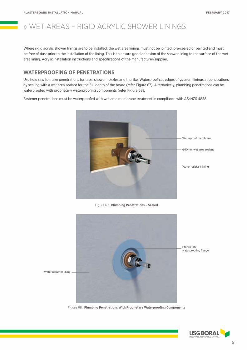
» WET AREAS – RIGID ACRYLIC SHOWER LININGS
51
PLASTERBOARD INSTALLATION MANUAL FEBRUARY 2017
WATERPROOFING OF PENETRATIONSUse hole saw to make penetrations for taps, shower nozzles and the like. Waterproof cut edges of gypsum linings at penetrations by sealing with a wet area sealant for the full depth of the board (refer Figure 67). Alternatively, plumbing penetrations can be waterproofed with proprietary waterproofing components (refer Figure 68).
Fastener penetrations must be waterproofed with wet area membrane treatment in compliance with AS/NZS 4858.
6-10mm wet area sealant
Waterproof membrane
Water resistant lining
Figure 67: Plumbing Penetrations – Sealed
Proprietary waterproofing flange
Water resistant lining
Figure 68: Plumbing Penetrations With Proprietary Waterproofing Components
Where rigid acrylic shower linings are to be installed, the wet area linings must not be jointed, pre-sealed or painted and must be free of dust prior to the installation of the lining. This is to ensure good adhesion of the shower lining to the surface of the wet area lining. Acrylic installation instructions and specifications of the manufacturer/supplier.
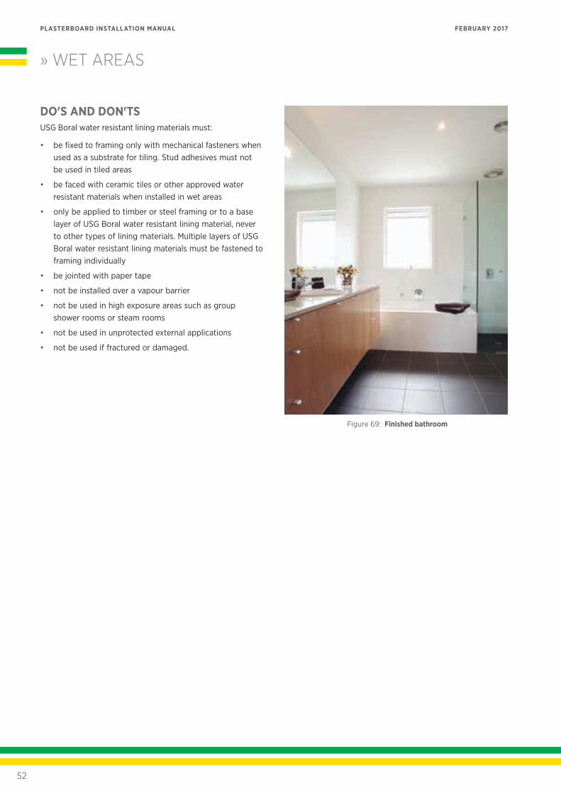
» WET AREAS
52
PLASTERBOARD INSTALLATION MANUAL FEBRUARY 2017
DO'S AND DON'TSUSG Boral water resistant lining materials must:
• be fixed to framing only with mechanical fasteners when used as a substrate for tiling. Stud adhesives must not be used in tiled areas
• be faced with ceramic tiles or other approved water resistant materials when installed in wet areas
• only be applied to timber or steel framing or to a base layer of USG Boral water resistant lining material, never to other types of lining materials. Multiple layers of USG Boral water resistant lining materials must be fastened to framing individually
• be jointed with paper tape
• not be installed over a vapour barrier
• not be used in high exposure areas such as group shower rooms or steam rooms
• not be used in unprotected external applications
• not be used if fractured or damaged.
Figure 69: Finished bathroom
CURVES AND ARCHES
Curves and arches can be constructed using USG Boral SHEETROCK, or for tight radii curves, 6.5mm FLEXIBOARD plasterboard.
CONSTRUCTING CURVED WALLS AND CEILINGSThe minimum bending radii for some USG Boral plasterboard products are as follows:
TABLE 28: BENDING RADII
PLASTERBOARD TYPE AND THICKNESS
MINIMUM BENDING RADIUS FOR PLASTERBOARD FIXED HORIZONTALLY
6.5mm FLEXIBOARD*650mm — concave
450mm — convex
10mm SHEETROCK 900mm
13mm SHEETROCK 1000mm
*To order only, minimum quantities may apply.
Shorter radii can be achieved by moistening the compressed face of plasterboard. When wetting the board, apply a small amount of clean water with a paint roller or sponge. Allow the water to soak for 15 minutes before attempting to bend the board. To prevent flat areas between the studs, space framing closer together than normal.
NOTES:
• Screw fasteners are preferable to nails to minimise possible impact damage.
• Avoid butt joints occurring in the curved section of the wall by using plasterboard sheets of suitable length.
• Make sure the sheet edge (or end) is correctly aligned to framing before driving fasteners.
• Ensure the board is in close contact with framing when fasteners are driven.
• To ensure a smooth curve, fasten in the field of board only where necessary.
• Fasten only to studs, not to top or bottom plates.
Refer to relevant USG Boral publication for detailed instructions on fixing of FLEXIBOARD plasterboard.
ARCHESInterior wall arches, framed in timber or steel, can be lined with SHEETROCK plasterboard and the arch angles reinforced with Arch Bead.
Straight corners below the arch line should be finished with standard corner bead.
Archway templates from min 12mm thick particleboard or MDF cut to the required profile must be in place before the installation of plasterboard sheets.
INSTALLATION• Fix plasterboard sheets, horizontally, to studs on one
side of the wall as per standard installation instructions.
• Screw/nail fix to templates and around the edge of the arch at maximum 300mm centres or use stud adhesive.
• Keep fasteners 10mm min from the edge of the arch.
• Do not place butt joints over or within 200mm of the arch.
• Allowing a 10mm projection beyond the template, accurately mark the profile of the arch on the back of the sheet.
• Cut out neatly with a keyhole saw.
• Fix sheets on the other side of the wall.
• From the cut side, square the line of cut across to the uncut sheet, mark the curve and cut out neatly as before.
• Cut a strip of plasterboard to fit into the arch soffit, allowing enough length to reach 50mm below the springing line on both sides of the arch.
• Apply continuous beads of cornice adhesive to the back edges of the wall sheets around the arch.
• If the arch has a tight radius, dampen the soffit strip to assist bending.
• Fasten one end of the soffit strip 50mm below the springing line and bed the strip into the cornice adhesive, progressively working around the arch.
• Check that the soffit strip is installed neatly and tightly throughout the arch and fix the free end.
• Cut plasterboard strips for the sides of the archway and fix using stud adhesive or fasteners.
• Bend Arch Bead into position around the arch with the short leg on the face of the wall. Allow a minimum of 150mm projection below the springing line at each end.
• Fix one end of the arch bead at the springing line, then fix around the remaining arch at maximum 300mm centres.
• Fit standard external corner beads to the straight sides of the archway and fix at maximum 300mm centres.
• Joint and finish as per standard methods.
53
PLASTERBOARD INSTALLATION MANUAL FEBRUARY 2017
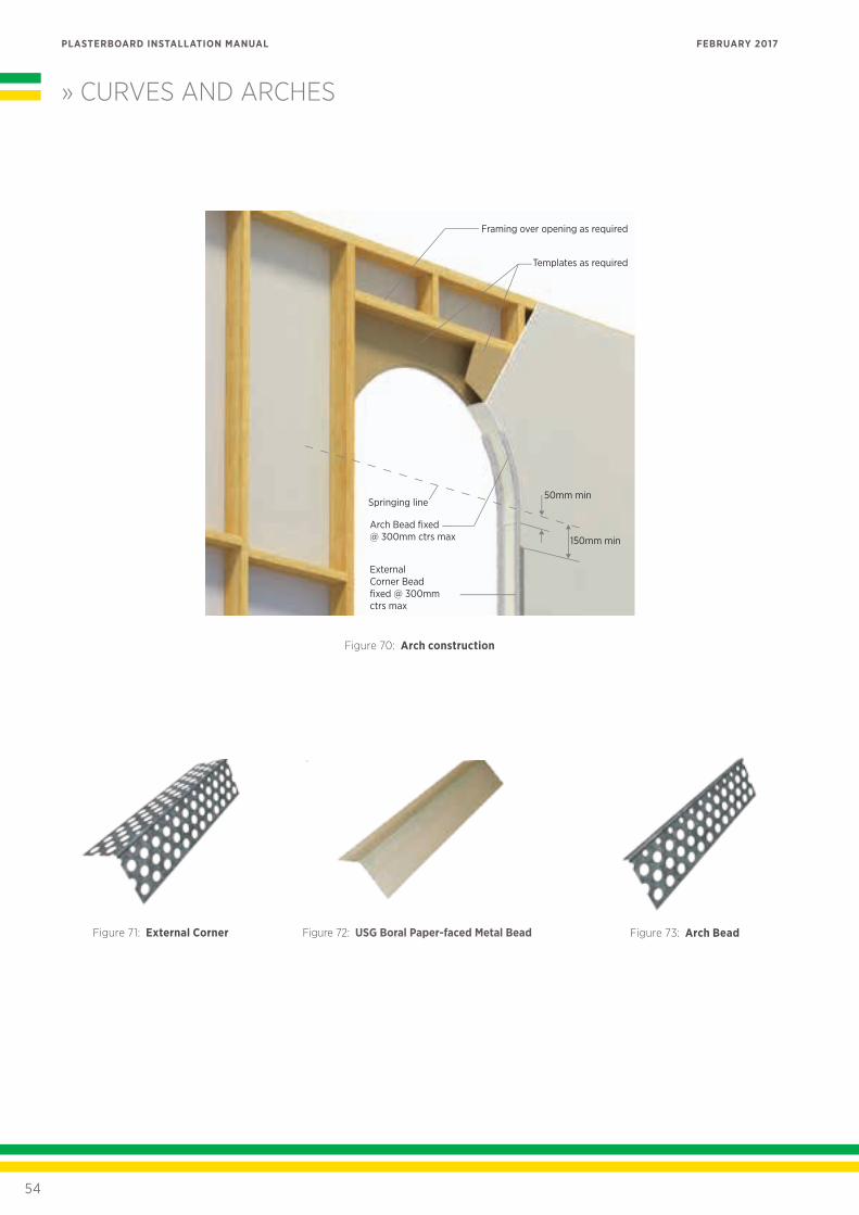
Framing over opening as required
Templates as required
50mm min
150mm min
Springing line
Arch Bead fixed @ 300mm ctrs max
External Corner Bead fixed @ 300mm ctrs max
» CURVES AND ARCHES
Figure 73: Arch BeadFigure 72: USG Boral Paper-faced Metal BeadFigure 71: External Corner
Figure 70: Arch construction
54
PLASTERBOARD INSTALLATION MANUAL FEBRUARY 2017
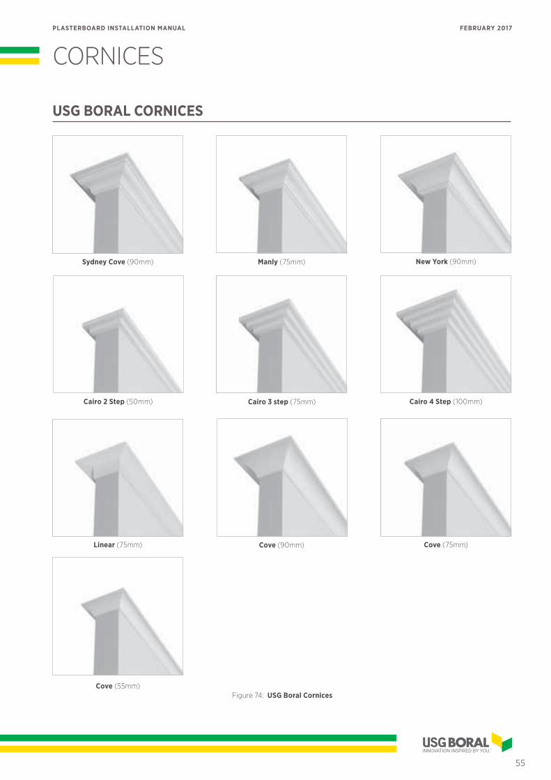
CORNICES
Cove (55mm)
New York (90mm)
Cairo 2 Step (50mm)
Cove (75mm)Cove (90mm)
Cairo 3 step (75mm)
Linear (75mm)
Sydney Cove (90mm) Manly (75mm)
Cairo 4 Step (100mm)
Figure 74: USG Boral Cornices
USG BORAL CORNICES
55
PLASTERBOARD INSTALLATION MANUAL FEBRUARY 2017

The installation specifications provided below are applicable to USG Boral paper faced cornices.
HANDLING AND LAYOUT• Ensure cornices are stacked neatly
away from traffic areas to protect profile and prevent damage.
• Cornice should be carried and handled 'on edge' to avoid cracking the core or wrinkling the paper liner.
• Where possible use full lengths of cornice and mitre all corner and butt joints.
• Ensure accurate and level placement by marking ceiling and walls with a line at the cornice edge.
• Install shorter lengths of cornice first then fit longer lengths by bowing out to spring mitres into place.
CUTTING CORNICE• Measure, mark and cut cornice with
a mitre cut each end, using a fine-tooth saw and a mitre box.
• Cut internal angles from the long point, and external angles from the short point.
• Check each cut piece of cornice for actual fit.
• Measure and precut cornice to length before mixing the cornice adhesive.
A
C
B
D
Figure 76: Finished Cornice
Figure 77: Cornice mitre box
Position A Position B
Position C Position D
Figure 75: Cutting cornices using a mitre box
» CORNICES
56
PLASTERBOARD INSTALLATION MANUAL FEBRUARY 2017
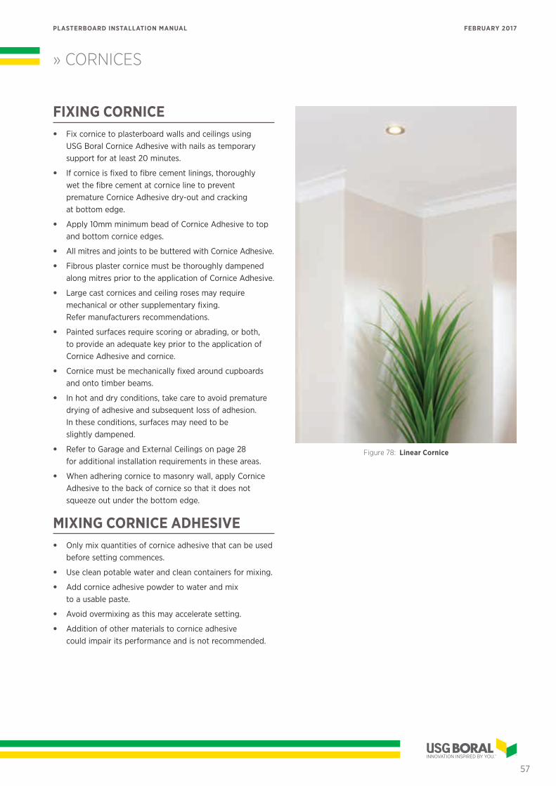
» CORNICES
FIXING CORNICE• Fix cornice to plasterboard walls and ceilings using
USG Boral Cornice Adhesive with nails as temporary support for at least 20 minutes.
• If cornice is fixed to fibre cement linings, thoroughly wet the fibre cement at cornice line to prevent premature Cornice Adhesive dry-out and cracking at bottom edge.
• Apply 10mm minimum bead of Cornice Adhesive to top and bottom cornice edges.
• All mitres and joints to be buttered with Cornice Adhesive.
• Fibrous plaster cornice must be thoroughly dampened along mitres prior to the application of Cornice Adhesive.
• Large cast cornices and ceiling roses may require mechanical or other supplementary fixing. Refer manufacturers recommendations.
• Painted surfaces require scoring or abrading, or both, to provide an adequate key prior to the application of Cornice Adhesive and cornice.
• Cornice must be mechanically fixed around cupboards and onto timber beams.
• In hot and dry conditions, take care to avoid premature drying of adhesive and subsequent loss of adhesion. In these conditions, surfaces may need to be slightly dampened.
• Refer to Garage and External Ceilings on page 28 for additional installation requirements in these areas.
• When adhering cornice to masonry wall, apply Cornice Adhesive to the back of cornice so that it does not squeeze out under the bottom edge.
MIXING CORNICE ADHESIVE• Only mix quantities of cornice adhesive that can be used
before setting commences.
• Use clean potable water and clean containers for mixing.
• Add cornice adhesive powder to water and mix to a usable paste.
• Avoid overmixing as this may accelerate setting.
• Addition of other materials to cornice adhesive could impair its performance and is not recommended.
Figure 78: Linear Cornice
57
PLASTERBOARD INSTALLATION MANUAL FEBRUARY 2017
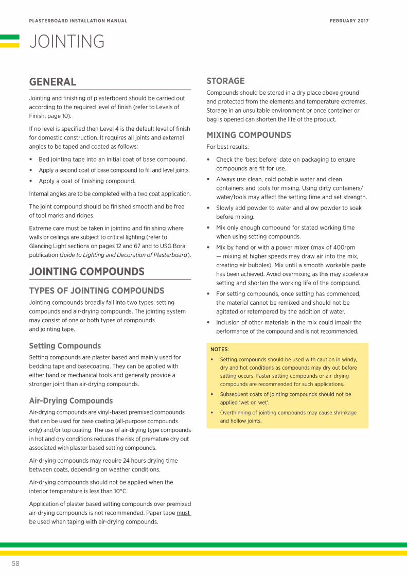
JOINTING
GENERALJointing and finishing of plasterboard should be carried out according to the required level of finish (refer to Levels of Finish, page 10).
If no level is specified then Level 4 is the default level of finish for domestic construction. It requires all joints and external angles to be taped and coated as follows:
• Bed jointing tape into an initial coat of base compound.
• Apply a second coat of base compound to fill and level joints.
• Apply a coat of finishing compound.
Internal angles are to be completed with a two coat application.
The joint compound should be finished smooth and be free of tool marks and ridges.
Extreme care must be taken in jointing and finishing where walls or ceilings are subject to critical lighting (refer to Glancing Light sections on pages 12 and 67 and to USG Boral publication Guide to Lighting and Decoration of Plasterboard).
JOINTING COMPOUNDS
TYPES OF JOINTING COMPOUNDSJointing compounds broadly fall into two types: setting compounds and air-drying compounds. The jointing system may consist of one or both types of compounds and jointing tape.
Setting CompoundsSetting compounds are plaster based and mainly used for bedding tape and basecoating. They can be applied with either hand or mechanical tools and generally provide a stronger joint than air-drying compounds.
Air-Drying CompoundsAir-drying compounds are vinyl-based premixed compounds that can be used for base coating (all-purpose compounds only) and/or top coating. The use of air-drying type compounds in hot and dry conditions reduces the risk of premature dry out associated with plaster based setting compounds.
Air-drying compounds may require 24 hours drying time between coats, depending on weather conditions.
Air-drying compounds should not be applied when the interior temperature is less than 10°C.
Application of plaster based setting compounds over premixed air-drying compounds is not recommended. Paper tape must be used when taping with air-drying compounds.
STORAGECompounds should be stored in a dry place above ground and protected from the elements and temperature extremes. Storage in an unsuitable environment or once container or bag is opened can shorten the life of the product.
MIXING COMPOUNDSFor best results:
• Check the ‘best before’ date on packaging to ensure compounds are fit for use.
• Always use clean, cold potable water and clean containers and tools for mixing. Using dirty containers/water/tools may affect the setting time and set strength.
• Slowly add powder to water and allow powder to soak before mixing.
• Mix only enough compound for stated working time when using setting compounds.
• Mix by hand or with a power mixer (max of 400rpm — mixing at higher speeds may draw air into the mix, creating air bubbles). Mix until a smooth workable paste has been achieved. Avoid overmixing as this may accelerate setting and shorten the working life of the compound.
• For setting compounds, once setting has commenced, the material cannot be remixed and should not be agitated or retempered by the addition of water.
• Inclusion of other materials in the mix could impair the performance of the compound and is not recommended.
NOTES:
• Setting compounds should be used with caution in windy, dry and hot conditions as compounds may dry out before setting occurs. Faster setting compounds or air-drying compounds are recommended for such applications.
• Subsequent coats of jointing compounds should not be applied 'wet on wet'.
• Overthinning of jointing compounds may cause shrinkage and hollow joints.
58
PLASTERBOARD INSTALLATION MANUAL FEBRUARY 2017
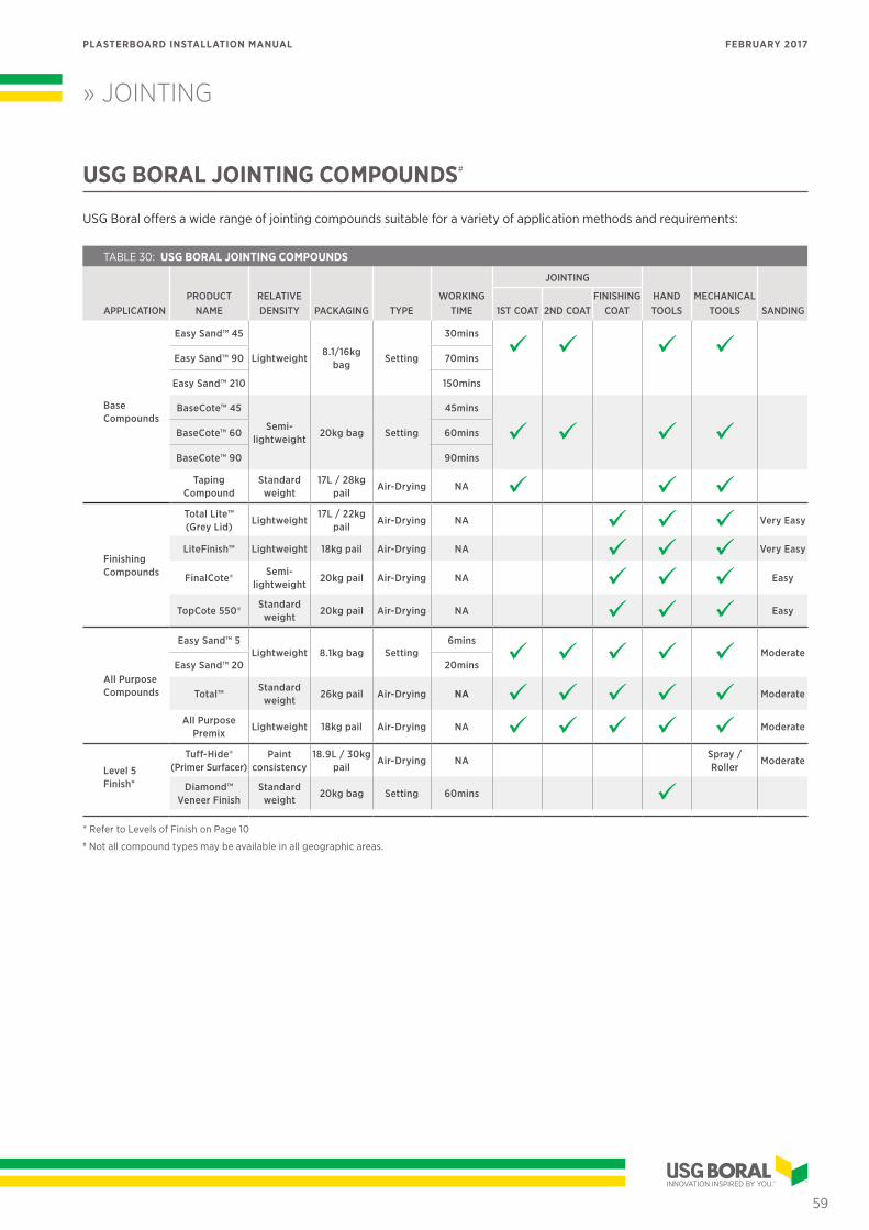
» JOINTING
USG BORAL JOINTING COMPOUNDS#
USG Boral offers a wide range of jointing compounds suitable for a variety of application methods and requirements:
TABLE 30: USG BORAL JOINTING COMPOUNDS
APPLICATIONPRODUCT
NAMERELATIVE DENSITY PACKAGING TYPE
WORKING TIME
JOINTING
HAND TOOLS
MECHANICAL TOOLS SANDING1ST COAT 2ND COAT
FINISHING COAT
Base Compounds
Easy Sand™ 45
Lightweight8.1/16kg
bagSetting
30mins
Easy Sand™ 90 70mins
Easy Sand™ 210 150mins
BaseCote™ 45
Semi-lightweight
20kg bag Setting
45mins
BaseCote™ 60 60mins
BaseCote™ 90 90mins
Taping Compound
Standard weight
17L / 28kg pail
Air-Drying NA
Finishing Compounds
Total Lite™ (Grey Lid)
Lightweight17L / 22kg
pailAir-Drying NA Very Easy
LiteFinish™ Lightweight 18kg pail Air-Drying NA Very Easy
FinalCote®Semi-
lightweight20kg pail Air-Drying NA Easy
TopCote 550®Standard
weight20kg pail Air-Drying NA Easy
All Purpose Compounds
Easy Sand™ 5Lightweight 8.1kg bag Setting
6mins
ModerateEasy Sand™ 20 20mins
Total™Standard
weight26kg pail Air-Drying NA Moderate
All Purpose Premix
Lightweight 18kg pail Air-Drying NA Moderate
Level 5 Finish*
Tuff-Hide® (Primer Surfacer)
Paint consistency
18.9L / 30kg pail
Air-Drying NASpray / Roller
Moderate
Diamond™ Veneer Finish
Standard weight
20kg bag Setting 60mins * Refer to Levels of Finish on Page 10# Not all compound types may be available in all geographic areas.
59
PLASTERBOARD INSTALLATION MANUAL FEBRUARY 2017
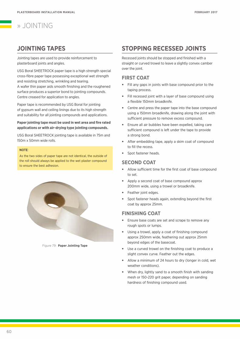
» JOINTING
JOINTING TAPESJointing tapes are used to provide reinforcement to plasterboard joints and angles.
USG Boral SHEETROCK paper tape is a high strength special cross-fibre paper tape possessing exceptional wet strength and resisting stretching, wrinkling and tearing. A wafer thin paper aids smooth finishing and the roughened surface produces a superior bond to jointing compounds. Centre creased for application to angles.
Paper tape is recommended by USG Boral for jointing of gypsum wall and ceiling linings due to its high strength and suitability for all jointing compounds and applications.
Paper jointing tape must be used in wet area and fire rated applications or with air-drying type jointing compounds.
USG Boral SHEETROCK jointing tape is available in 75m and 150m x 50mm wide rolls.
NOTE:
As the two sides of paper tape are not identical, the outside of the roll should always be applied to the wet plaster compound to ensure the best adhesion.
Figure 79: Paper Jointing Tape
STOPPING RECESSED JOINTSRecessed joints should be stopped and finished with a straight or curved trowel to leave a slightly convex camber over the joint.
FIRST COAT• Fill any gaps in joints with base compound prior to the
taping process.
• Fill recessed joint with a layer of base compound using a flexible 150mm broadknife.
• Centre and press the paper tape into the base compound using a 150mm broadknife, drawing along the joint with sufficient pressure to remove excess compound.
• Ensure all air bubbles have been expelled, taking care sufficient compound is left under the tape to provide a strong bond.
• After embedding tape, apply a skim coat of compound to fill the recess.
• Spot fastener heads.
SECOND COAT• Allow sufficient time for the first coat of base compound
to set.
• Apply a second coat of base compound approx 200mm wide, using a trowel or broadknife.
• Feather joint edges.
• Spot fastener heads again, extending beyond the first coat by approx 25mm.
FINISHING COAT• Ensure base coats are set and scrape to remove any
rough spots or lumps.
• Using a trowel, apply a coat of finishing compound approx 250mm wide, feathering out approx 25mm beyond edges of the basecoat.
• Use a curved trowel on the finishing coat to produce a slight convex curve. Feather out the edges.
• Allow a minimum of 24 hours to dry (longer in cold, wet weather conditions).
• When dry, lightly sand to a smooth finish with sanding mesh or 150-220 grit paper, depending on sanding hardness of finishing compound used.
60
PLASTERBOARD INSTALLATION MANUAL FEBRUARY 2017
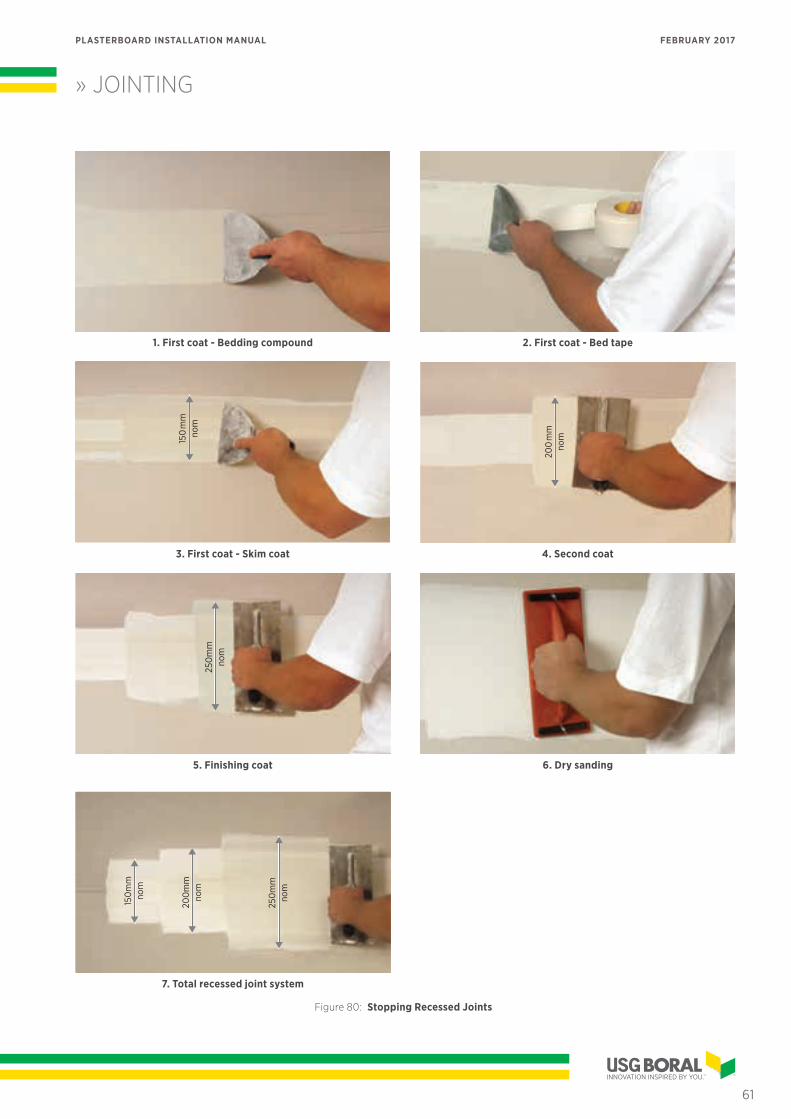
1. First coat - Bedding compound
150
mm
nom
3. First coat - Skim coat
250
mm
nom
5. Finishing coat
250
mm
nom
200
mm
nom
150
mm
nom
7. Total recessed joint system
2. First coat - Bed tape
200
mm
nom
4. Second coat
6. Dry sanding
Figure 80: Stopping Recessed Joints
61
PLASTERBOARD INSTALLATION MANUAL FEBRUARY 2017
» JOINTING
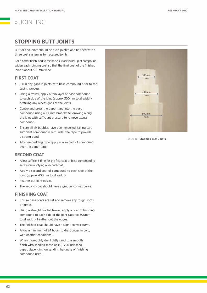
STOPPING BUTT JOINTSButt or end joints should be flush-jointed and finished with a three coat system as for recessed joints.
For a flatter finish, and to minimise surface build-up of compound, widen each jointing coat so that the final coat of the finished joint is about 500mm wide.
FIRST COAT• Fill in any gaps in joints with base compound prior to the
taping process.
• Using a trowel, apply a thin layer of base compound to each side of the joint (approx 300mm total width) prefilling any recess gaps at the joints.
• Centre and press the paper tape into the base compound using a 150mm broadknife, drawing along the joint with sufficient pressure to remove excess compound.
• Ensure all air bubbles have been expelled, taking care sufficient compound is left under the tape to provide a strong bond.
• After embedding tape apply a skim coat of compound over the paper tape.
SECOND COAT• Allow sufficient time for the first coat of base compound to
set before applying a second coat.
• Apply a second coat of compound to each side of the joint (approx 400mm total width).
• Feather out joint edges.
• The second coat should have a gradual convex curve.
FINISHING COAT• Ensure base coats are set and remove any rough spots
or lumps.
• Using a straight bladed trowel, apply a coat of finishing compound to each side of the joint (approx 500mm total width). Feather out the edges.
• The finished coat should have a slight convex curve.
• Allow a minimum of 24 hours to dry (longer in cold, wet weather conditions).
• When thoroughly dry, lightly sand to a smooth finish with sanding mesh or 150–220 grit sand paper, depending on sanding hardness of finishing compound used.
500mmnom
400mmnom
300mmnom
Figure 81: Stopping Butt Joints
62
PLASTERBOARD INSTALLATION MANUAL FEBRUARY 2017
» JOINTING
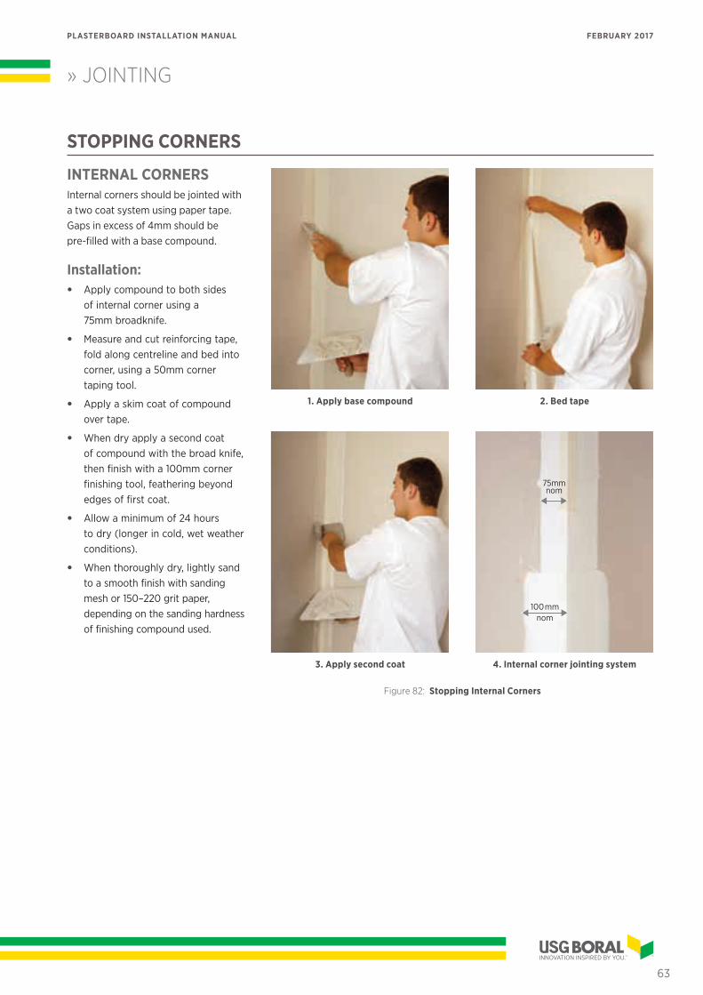
STOPPING CORNERS
INTERNAL CORNERSInternal corners should be jointed with a two coat system using paper tape. Gaps in excess of 4mm should be pre-filled with a base compound.
Installation:• Apply compound to both sides
of internal corner using a 75mm broadknife.
• Measure and cut reinforcing tape, fold along centreline and bed into corner, using a 50mm corner taping tool.
• Apply a skim coat of compound over tape.
• When dry apply a second coat of compound with the broad knife, then finish with a 100mm corner finishing tool, feathering beyond edges of first coat.
• Allow a minimum of 24 hours to dry (longer in cold, wet weather conditions).
• When thoroughly dry, lightly sand to a smooth finish with sanding mesh or 150–220 grit paper, depending on the sanding hardness of finishing compound used.
1. Apply base compound
3. Apply second coat
2. Bed tape
100mmnom
75mmnom
4. Internal corner jointing system
Figure 82: Stopping Internal Corners
63
PLASTERBOARD INSTALLATION MANUAL FEBRUARY 2017
» JOINTING
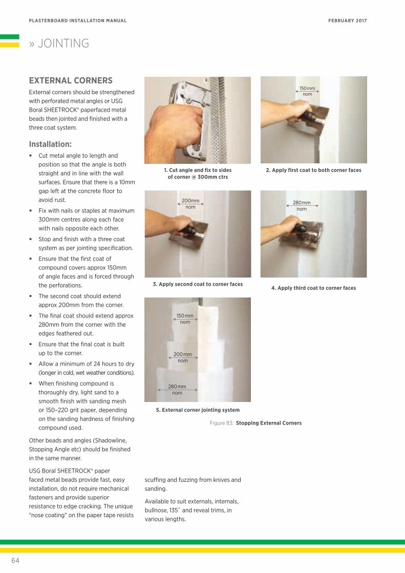
EXTERNAL CORNERSExternal corners should be strengthened with perforated metal angles or USG Boral SHEETROCK® paperfaced metal beads then jointed and finished with a three coat system.
Installation:• Cut metal angle to length and
position so that the angle is both straight and in line with the wall surfaces. Ensure that there is a 10mm gap left at the concrete floor to avoid rust.
• Fix with nails or staples at maximum 300mm centres along each face with nails opposite each other.
• Stop and finish with a three coat system as per jointing specification.
• Ensure that the first coat of compound covers approx 150mm of angle faces and is forced through the perforations.
• The second coat should extend approx 200mm from the corner.
• The final coat should extend approx 280mm from the corner with the edges feathered out.
• Ensure that the final coat is built up to the corner.
• Allow a minimum of 24 hours to dry (longer in cold, wet weather conditions).
• When finishing compound is thoroughly dry, light sand to a smooth finish with sanding mesh or 150–220 grit paper, depending on the sanding hardness of finishing compound used.
Other beads and angles (Shadowline, Stopping Angle etc) should be finished in the same manner.
USG Boral SHEETROCK® paper faced metal beads provide fast, easy installation, do not require mechanical fasteners and provide superior resistance to edge cracking. The unique "nose coating" on the paper tape resists
1. Cut angle and fix to sides of corner @ 300mm ctrs
200mmnom
3. Apply second coat to corner faces
150mmnom
2. Apply first coat to both corner faces
280mmnom
4. Apply third coat to corner faces
Figure 83: Stopping External Corners
5. External corner jointing system
280mmnom
200mmnom
150mmnom
scuffing and fuzzing from knives and sanding.
Available to suit externals, internals, bullnose, 135˚ and reveal trims, in various lengths.
64
PLASTERBOARD INSTALLATION MANUAL FEBRUARY 2017
» JOINTING
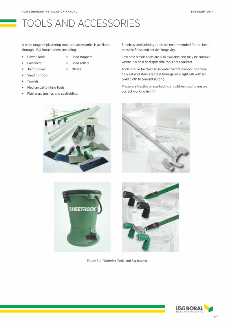
TOOLS AND ACCESSORIES
A wide range of plastering tools and accessories is available through USG Boral outlets, including:
• Power Tools • Bead hoppers
• Fasteners • Bead rollers
• Joint Knives • Mixers
• Sanding tools
• Trowels
• Mechanical jointing tools
• Plasterers trestles and scaffolding.
Stainless steel jointing tools are recommended for the best possible finish and service longevity.
Low cost plastic tools are also available and may be suitable where low cost or disposable tools are required.
Tools should be cleaned in water before compounds have fully set and stainless steel tools given a light rub with an oiled cloth to prevent rusting.
Plasterers trestles or scaffolding should be used to ensure correct working height.
Figure 84: Plastering Tools and Accessories
65
PLASTERBOARD INSTALLATION MANUAL FEBRUARY 2017
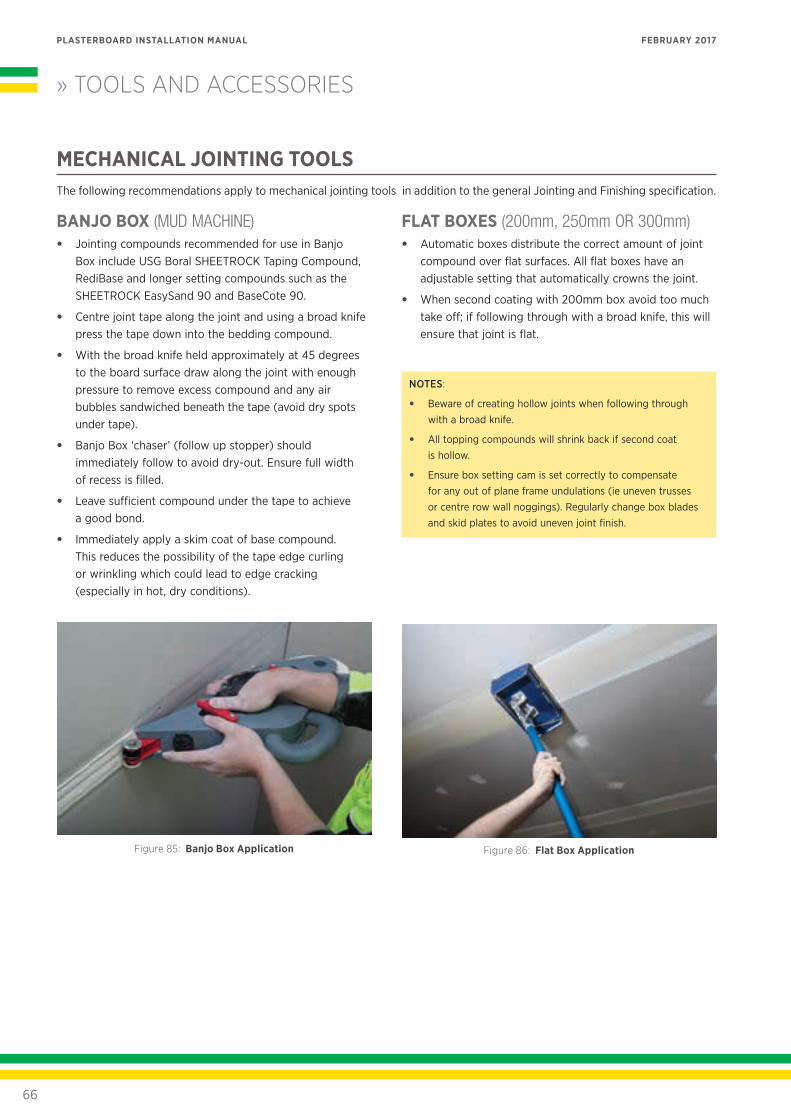
MECHANICAL JOINTING TOOLSThe following recommendations apply to mechanical jointing tools in addition to the general Jointing and Finishing specification.
BANJO BOX (MUD MACHINE)• Jointing compounds recommended for use in Banjo
Box include USG Boral SHEETROCK Taping Compound, RediBase and longer setting compounds such as the SHEETROCK EasySand 90 and BaseCote 90.
• Centre joint tape along the joint and using a broad knife press the tape down into the bedding compound.
• With the broad knife held approximately at 45 degrees to the board surface draw along the joint with enough pressure to remove excess compound and any air bubbles sandwiched beneath the tape (avoid dry spots under tape).
• Banjo Box ‘chaser’ (follow up stopper) should immediately follow to avoid dry-out. Ensure full width of recess is filled.
• Leave sufficient compound under the tape to achieve a good bond.
• Immediately apply a skim coat of base compound. This reduces the possibility of the tape edge curling or wrinkling which could lead to edge cracking (especially in hot, dry conditions).
Figure 85: Banjo Box Application
FLAT BOXES (200mm, 250mm OR 300mm)• Automatic boxes distribute the correct amount of joint
compound over flat surfaces. All flat boxes have an adjustable setting that automatically crowns the joint.
• When second coating with 200mm box avoid too much take off; if following through with a broad knife, this will ensure that joint is flat.
NOTES:
• Beware of creating hollow joints when following through with a broad knife.
• All topping compounds will shrink back if second coat is hollow.
• Ensure box setting cam is set correctly to compensate for any out of plane frame undulations (ie uneven trusses or centre row wall noggings). Regularly change box blades and skid plates to avoid uneven joint finish.
Figure 86: Flat Box Application
» TOOLS AND ACCESSORIES
66
PLASTERBOARD INSTALLATION MANUAL FEBRUARY 2017
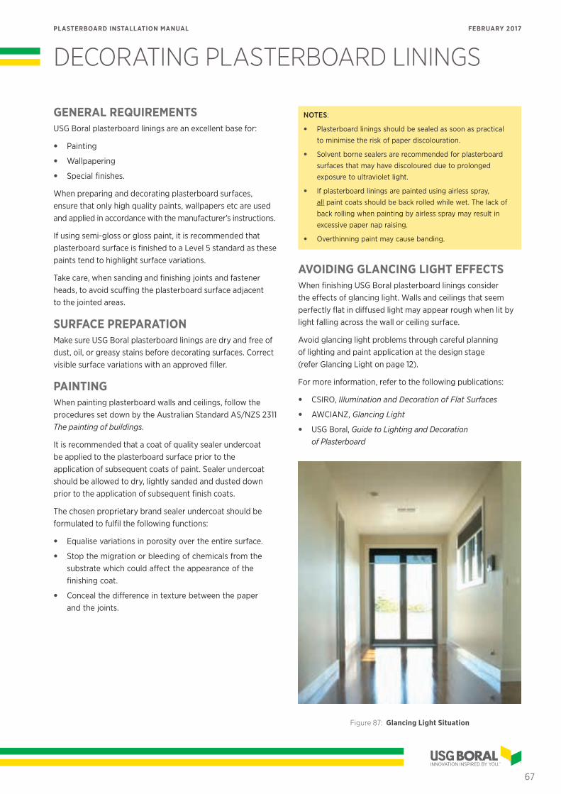
DECORATING PLASTERBOARD LININGS
GENERAL REQUIREMENTSUSG Boral plasterboard linings are an excellent base for:
• Painting
• Wallpapering
• Special finishes.
When preparing and decorating plasterboard surfaces, ensure that only high quality paints, wallpapers etc are used and applied in accordance with the manufacturer’s instructions.
If using semi-gloss or gloss paint, it is recommended that plasterboard surface is finished to a Level 5 standard as these paints tend to highlight surface variations.
Take care, when sanding and finishing joints and fastener heads, to avoid scuffing the plasterboard surface adjacent to the jointed areas.
SURFACE PREPARATIONMake sure USG Boral plasterboard linings are dry and free of dust, oil, or greasy stains before decorating surfaces. Correct visible surface variations with an approved filler.
PAINTINGWhen painting plasterboard walls and ceilings, follow the procedures set down by the Australian Standard AS/NZS 2311 The painting of buildings.
It is recommended that a coat of quality sealer undercoat be applied to the plasterboard surface prior to the application of subsequent coats of paint. Sealer undercoat should be allowed to dry, lightly sanded and dusted down prior to the application of subsequent finish coats.
The chosen proprietary brand sealer undercoat should be formulated to fulfil the following functions:
• Equalise variations in porosity over the entire surface.
• Stop the migration or bleeding of chemicals from the substrate which could affect the appearance of the finishing coat.
• Conceal the difference in texture between the paper and the joints.
NOTES:
• Plasterboard linings should be sealed as soon as practical to minimise the risk of paper discolouration.
• Solvent borne sealers are recommended for plasterboard surfaces that may have discoloured due to prolonged exposure to ultraviolet light.
• If plasterboard linings are painted using airless spray, all paint coats should be back rolled while wet. The lack of back rolling when painting by airless spray may result in excessive paper nap raising.
• Overthinning paint may cause banding.
AVOIDING GLANCING LIGHT EFFECTSWhen finishing USG Boral plasterboard linings consider the effects of glancing light. Walls and ceilings that seem perfectly flat in diffused light may appear rough when lit by light falling across the wall or ceiling surface.
Avoid glancing light problems through careful planning of lighting and paint application at the design stage (refer Glancing Light on page 12).
For more information, refer to the following publications:
• CSIRO, Illumination and Decoration of Flat Surfaces
• AWCIANZ, Glancing Light
• USG Boral, Guide to Lighting and Decoration of Plasterboard
Figure 87: Glancing Light Situation
67
PLASTERBOARD INSTALLATION MANUAL FEBRUARY 2017
PRODUCT INFORMATION
See USGBoral.com for the most up-to-date product information.
NOTEProducts described here may not be available in all areas. Consult your USG Boral sales office or representative for information.
SALES ENQUIRIESAuckland (09) 270-2595
Wellington (04) 560-4528
Christchurch (03) 365-4245
TECHNICAL ASSISTANCE0800 USGBORAL (0800 874-267)
USGBoral.com
There are many variables that can influence construction projects, which affect whether a particular construction technique is appropriate. Before proceeding with any project, we recommend you obtain professional advice to ascertain the appropriate construction techniques to suit the particular circumstances of your project. We recommend you use qualified tradespersons to install this system.
The technical information contained in this manual was correct at the time of printing. Building systems, details and product availability are, however, subject to change. To ensure the information you are using is current, USG Boral recommends you review the latest building information available on the USG Boral website.
For further information, contact TecASSIST™ or your nearest USG Boral sales office.
PB105/2 1 FEBRUARY 2017
© 2017 USG BORAL. All rights reserved. The trademarks USG BORAL, INNOVATION INSPIRED BY YOU, TecASSIST, Echostop, Firestop, Multistop, Flexiboard, Shaftliner, BaseCote, LiteFinish, TopCote 550, FinalCote, Wet Area System are trademarks or registered trademarks of USG Boral Building Products or one or more of its affiliates. SHEETROCK, Easy Sand, Total, Total Lite and Diamond Veneer are trademarks owned by United States Gypsum Company and used under license. FIBEROCK and Tuff-Hide are trademarks owned by USG Interiors Pacific Limited and used under license.