Embed Size (px)
Citation preview
Australia
LOOSE NUT CONNECTIONS
SINK
TRAPPED WASTE
Australia
LOOSE NUT CONNECTION
TUNDISH
TRAPPED WASTE
PLASTER TRAPINSTALLATION GUIDELINES
Plaster Traps are to be installed in a convenient position under the sinkand away from electrical and electronic devices. They require sufficientheadroom for removal and emptying of the inner solids Trap bucket.
The Sink Dropper is to be of sufficient length to ensure splashing does not occur. It must have a loose nut connection to the waste outlet for removal. This allows the inner Trap solids bucket to be removed and cleaned.Allow 270mm gap between the bottom of sink and top of trap for removable purposes
The Outlet must also have a loose nut connection located as close as practicable to the unit for removal and cleaning purposes.
The Outlet is to have a greater discharge capacity than the Inlet to prevent overflows.
Cleaning frequency is governed by the type of solids and liquids discharged into the Trap but it is recommended that maintenanceand cleaning of the Removable Trap occur bi-monthly and the overallTrap be removed and cleaned annually.
All installations are to comply with the relevant Australian/New Zealand Standards and local Government requirements.
STORM PLASTICS (SA) Pty Ltd www.stormplastics.com.au
BOTTOM OUTLET SIDE OUTLET
REMOVABLE TRAP
Minimumdistance
= 270 mm
SINK
HANDLE
HANDLE
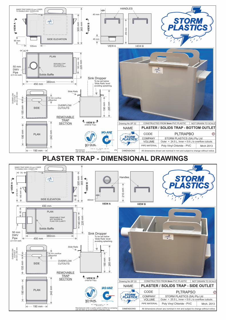
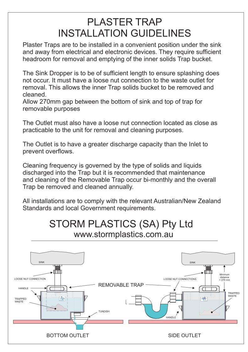
PLASTER TRAP - DIMENSIONAL DRAWINGS
Australia
SIDE ELEVATION
PLAN
REMOVABLE TRAPNOT SHOWN IN PLAN FOR CLARITY
VIEW B
90 mm
220 m
m
Outer = 24.5 L, Inner = 5.6 L to overflow cutouts.
PLTRAPBO
VOLUME
Mrch 2013
VIEW A
PLASTER / SOLIDS TRAP - BOTTOM OUTLET
105mm
45 mm
CODE
DIMENSIONS
NAME
Poly Vinyl Chloride - PVC
COMPANY STORM PLASTICS (SA) Pty Ltd
NOT DRAWN TO SCALE
Manufactured under a quality system certified as complyingwith ISO 9001 by an accredited certification body
Drawing No.SP 32
PIPE MATERIAL
All dimensions shown are nominal in mm and subject to change without notice.
CONSTRUCTED FROM 6mm PVC PLASTIC
50 mmDWVPipe
(2.5 mm wall)
INNER TRAP SIDES 20 mm LOWERTO ENABLE MAX. OVERFLOW
190 mm
242 m
m
380mm
155 m
m
Solids Baffle
PLAN
SIDE
190 m
m
REMOVABLETRAP
SECTION
190 m
m
265 m
m
Sink DropperTo be set below‘Slide Rails’ levelavoiding splashing.
Slide Rails
OVERFLOWCUTOUTS
OV
ER
FLO
WC
UT
OU
T20 m
m x
80 m
m
VIEW B(Internal Trap)
34 mm overflowdifferential
VIE
W A
VIE
W B
365 m
m305 m
m
450 mm
35
HANDLES
40 mm
25
0 m
m
14
0 m
m
Australia
SIDE ELEVATION
PLAN
REMOVABLE TRAPNOT SHOWN IN PLAN FOR CLARITY
VIEW B
190 mm
242 m
m
380mm
155 m
m
210 m
m
365 m
m
210 m
m
Outer = 25.5 L, Inner = 5.6 L to overflow cutouts.
Solids Baffle
Handles
50 mmDWVPipe
305 m
m
PLTRAPSO
Mrch. 2013
VIEW A
PLAN
SIDE
190 m
m PLASTER / SOLIDS TRAP - SIDE OUTLET
CODE
DIMENSIONS
NAME
Poly Vinyl Chloride - PVC
COMPANY STORM PLASTICS (SA) Pty Ltd
NOT DRAWN TO SCALE
Manufactured under a quality system certified as complyingwith ISO 9001 by an accredited certification body
Drawing No.SP 33
PIPE MATERIAL
All dimensions shown are nominal in mm and subject to change without notice.
VOLUME
CONSTRUCTED FROM 6mm PVC PLASTIC
REMOVABLETRAP
SECTION
190 m
m
265 m
m
Sink DropperTo be set below‘Slide Rails’ levelavoiding splashing.
Slide Rails
OVERFLOWCUTOUTS
INNER TRAP SIDES 20 mm LOWERTO ENABLE MAX. OVERFLOW
220 m
m
40mm
140 m
m83
140 m
m
OV
ER
FLO
WC
UT
OU
T20 m
m x
80 m
m
75
35
VIE
W A
VIEW B
VIE
W B
(Internal Trap)
(2.5 mm wall)
34 mm overflowdifferential
450 mm
490 mm
PHOTO 3D ACTUAL UNIT