Embed Size (px)
Citation preview

P91.deTechnical Brochure
Plaster and Façade Systems
2021-06
MP 75 L FireFire Protection Gypsum PlasterPlaning Aid
Note on English translation / Hinweise zur englischen FassungThis is a translation of the Technical Brochure valid in Germany. All stated details and properties are in compliance with the regulations of the German standards and building regulations. They are only applicable for the specified products, system components, application rules, and construction details in connection with the specifications of the respective certificates and approvals.Knauf Gips KG denies any liability for applications outside of Germany as this requires changes acc. to the respective national standards and building regulations.
Dies ist eine Übersetzung des in Deutschland gültigen Technische Broschüres. Alle angegebenen Werte und Eigenschaften entsprechen den in Deutschland gültigen Normen und bauaufsichtlichen Regelungen. Sie gelten nur bei Verwendung der angegebenen Produkte, Systemkomponenten, Anwendungsregeln und Konstruktionsdetails in Verbindung mit den Vorgaben der bauaufsichtlichen Nachweise.Die Knauf Gips KG lehnt jegliche Haftung für Einsatz und Anwendung außerhalb Deutschlands ab, da in diesem Fall eine Anpassung an nationale Normen und bauaufsichtliche Regelungen notwendig ist.
2 P91.de MP 75 L Fire
ContentsMP 75 L Fire
Fire protection gypsum plaster .....................................................................................................................................................4
Steel structuresColumns and beams .......................................................................................................................................................................6
Determination of U/A ratios .........................................................................................................................................................7U/A values overview ....................................................................................................................................................................8Minimum application layer thickness e ...................................................................................................................................... 11Rating examples .......................................................................................................................................................................13
Vaulted and hollow clay element ceilings ..................................................................................................................................14
Concrete constructionsColumns and beams .....................................................................................................................................................................16
Minimum application layer thickness e .....................................................................................................................................17Rating examples .......................................................................................................................................................................19
Ceilings and walls .........................................................................................................................................................................20Minimum application layer thickness e .....................................................................................................................................21Rating example .........................................................................................................................................................................24
Ribbed and dropped ceilings ......................................................................................................................................................25Rating example .........................................................................................................................................................................26
Reinforced concrete hollow ceilings ..........................................................................................................................................27Rating example .........................................................................................................................................................................28
Concrete composite ceilingsTrapezoid sheet concrete composite ceilings ...........................................................................................................................30
Minimum application layer thickness e ......................................................................................................................................30Rating example .........................................................................................................................................................................30
Usage instructionsNotes ..............................................................................................................................................................................................31
Photo: Knauf/Ralf Heikaus
MP 75 L FireFire protection gypsum plaster

4 P91.de MP 75 L Fire
MP 75 L FireFire protection gypsum plaster
Product descriptionMP 75L Fire has been developed specially for fire protection of buildings in interiors. Its task is to protect the load bearing coated construction elements in the event of a fire so that their function is maintained until the fire has been extinguished or building evacuated.MP 75 L Fire consists of gypsum as a binder in combination with a special mix of lightweight aggregates and additives to ensure good machine application. MP 75 L Fire has been granted the European Technical Approval ETA-11/0229.
Field of application ■ Steel columns and beams acc. to EN 1993-1-2 ■ Concrete beams and supports acc. to EN 1992-1-2 ■ Concrete ceilings and walls acc. to EN 1992-1-2 ■ Trapezoid sheet metal with concrete acc. to EN 1994-1-2
Properties and added value ■ Easy machine application ■ Notably higher yield than comparable products ■ Gypsum based ■ For interior use ■ Colour white
Technical data
Description Standard Unit Value
Reaction to fire EN 13501-1 Class A1Compressive strength EN 13279-2 N/mm2 ≥ 1.7Bond strength
■ on concrete and steel ■ on galvanized sheet metal
EN 1015-2N/mm2
N/mm2≥ 0.1≥ 0.05
Water vapour diffusion resistance EN 12086 – 8pH value – – 12 – 13Initial setting time – min approx. 90 - 170Final setting time – min approx. 180 - 300Bulk density – kg/m3 500 – 600Dry density EN 1015-10 kg/m3 approx. 750Weight of dried plaster – kg/mm/m2 approx. 0.8The stated technical data were evaluated acc. to the respective test standards. Deviations under site conditions are possible.
Material requirement and efficiencyApplication Consumption approx. Yield approx.
kg/m2 m²/bag m2/t10 mm application thickness 6.7 3.0 150.0
All stated figures are approximate values and may deviate depending on the substrate conditions. The exact consumption can only be determined on the indi-vidual object.
Notes on fire resistanceThe application options and the fire protection properties of the MP 75 L Fire stated here are based on the data of the European Technical Approval ETA 11/0229 and the test reports on which it is based. All specifications marked with offer the user additional application options, which are not directly included in the European Certificate of Usability, but which have been technically assessed on the basis of the experts report GS 3.2/15-094-1 by the MFPA Leipzig.The basis for the experts report GS 3.2/15-094-1 are, in addition to the DIN 4102-4 (Fire behaviour of building materials and building components) and the EN 13381-3 /-4 (Test methods for determining the contribution to the fire resistance of structural members), the test reports on which the ETA 11/0229 is based. We will make this technical assessment available to you together with the Certificate of Usability.
Knauf wishes to point out that before the fire protection enhancement with MP 75 L Fire, the construction and implementation including all those in the planning aid marked with should in every case be coordinated and authorised in advance in consultation between the persons responsible for fire resistance and/or the relevant authorities. The Knauf Planning Aid P91.de provides an overview of all areas of application classified as feasible from a fire resistance perspective. The plaster thicknesses specified here are compliant with ETA 11/0229 or were calculated in accordance with the specifications of the EN 1992-1-2 (Eurocode 2: Design of concrete structures Part 1–2: General rules - Structural fire design. All plaster thickness are valid exclusively when the stated specifications are complied with in detail.The layer thicknesses are minimum thicknesses that must be strictly observed. It is not permissible to apply a second layer after the plaster has hardened. For this reason, we recommend application of a layer thickness that is always 10 to 20% more than the minimum to avoid the risk of layer thicknesses that are too thin.
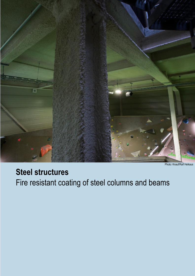
Steel structuresFire resistant coating of steel columns and beams
Photo: Knauf/Ralf Heikaus

6 P91.de MP 75 L Fire
Steel structuresColumns and beams
Fire resistant coatingMP 75 L Fire can be used as a fire resistant coating with the following profiles and exposure to fire.Profiles
■ I profiles ■ H profiles ■ L profiles ■ T profiles ■ U profiles ■ Hollow sections
Exposure to fire ■ 4-sided ■ 3-sided ■ 2-sided ■ 1-sided
The rating of the plaster thickness of MP 75 L Fire required for fire resistance purposes on steel columns and beams is in accordance with table 3 on pages 11/12 and depends on the following 3 parameters:
■ Ratio of the surface on which the heat acts (circumference) U to the profile cross-section area A of the steel cross-section to be protected, the so-called U/A value; it is determined in accordance with page 7 taking the installation conditions into consideration.
A
U
U = Circumference of the steel profile exposed to fire (cm) A = Profile cross-section (cm2) The maximum permissible U/A factor is 540 m-1. For common profile cross-sections the U/A values can be found in table 2 on pages 8/9/10.
■ The required fire resistance class R (retention of the stability) according to building authority requirements.
■ Critical steel temperature, used when dimensioning acc. to EN 1993-1-2 (determined by the structural design engineer)
Protective treatment of the steel components treated using an epoxy resin, alkyd or zinc-silicate based corrosion-proof coating is required.The used U/A ratio value (profile ratio) corresponds to the ratio Ap/V in the EN 1993-1-2.Round up the results when calculating the U/A values.
Technical fire resistance assessed acc. to GS 3.2/15-094-1
■ Prior consultation acc. to note on page 4 is recommended
7P91.de MP 75 L Fire
Steel structuresColumns and beams
Construction features b, h, s and t in cm; area A in cm2
Exposure to fire
U/A m-1
Hollow section, corner
A
t
b
h
All-sided
Hollow section, round
A
t
d
All-sided
L profile
h
b
t
A
All-sided
U profile
h
b
t
s
A
3-sided
U profile
h
b
t
s
A
All-sided
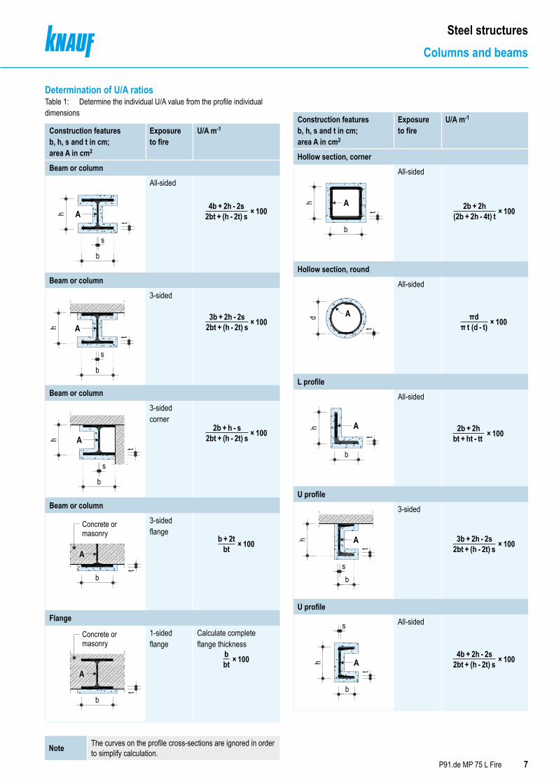
Determination of U/A ratiosTable 1: Determine the individual U/A value from the profile individual dimensions
Construction features b, h, s and t in cm; area A in cm2
Exposure to fire
U/A m-1
Beam or column
b
s
h
t
A
All-sided
Beam or column
h A
b
s
t
3-sided
Beam or column
h
t
b
s
A
3-sided corner
Beam or column
b
A
t
Concrete ormasonry
3-sided flange
Flange
b
t
A
Concrete ormasonry
1-sided flange
Calculate complete flange thickness
Note The curves on the profile cross-sections are ignored in order to simplify calculation.
Construction features b, h, s and t in cm; area A in cm2
Exposure to fire
U/A m-1
Hollow section, corner
A
t
b
h
All-sided
Hollow section, round
A
t
d
All-sided
L profile
h
b
t
A
All-sided
U profile
h
b
t
s
A
3-sided
U profile
h
b
t
s
A
All-sided
4b + 2h - 2s2bt + (h - 2t) s × 100 × 100
× 100
× 100
× 100
× 100
× 100
× 100
3b + 2h - 2s
2b + h - s
b + 2t
2bt + (h - 2t) s
2bt + (h - 2t) s
bt
2b + 2h
3b + 2h - 2s
2b + 2h
πd
(2b + 2h - 4t) t
2bt + (h - 2t) s
bt + ht - tt
π t (d - t)
× 100× 100bbt
4b + 2h - 2s2bt + (h - 2t) s
8 P91.de MP 75 L Fire
Steel structuresColumns and beams
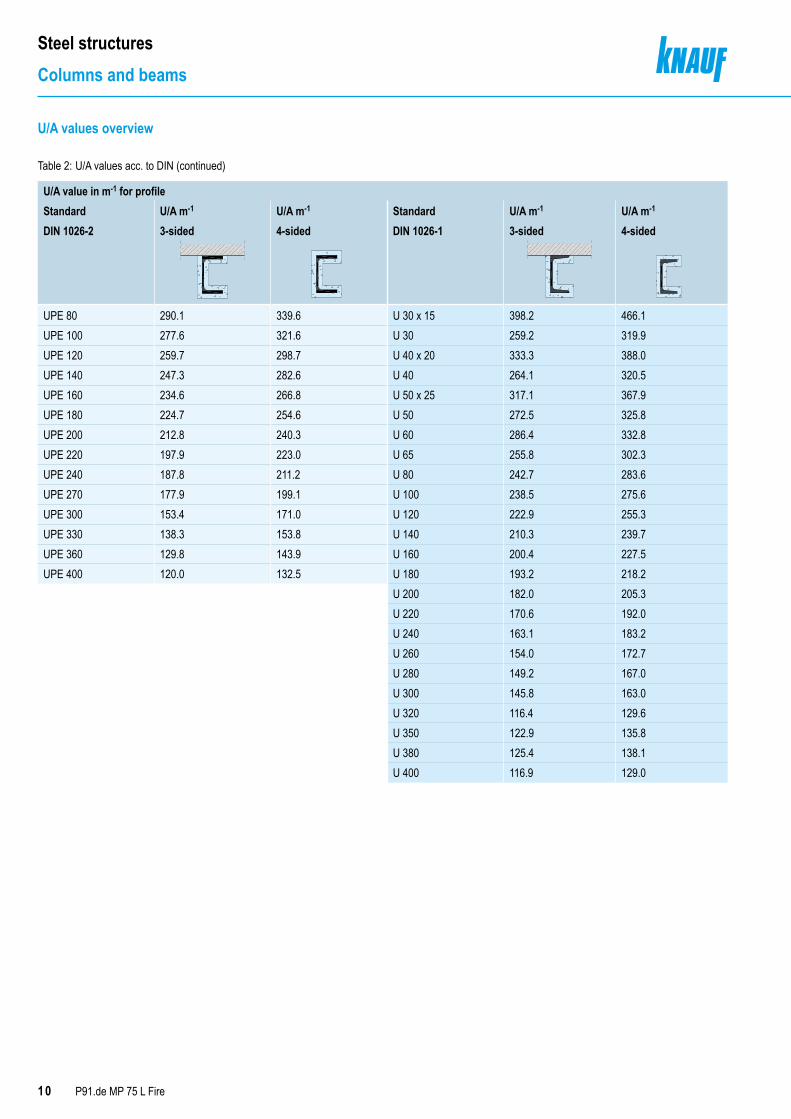
U/A values overview
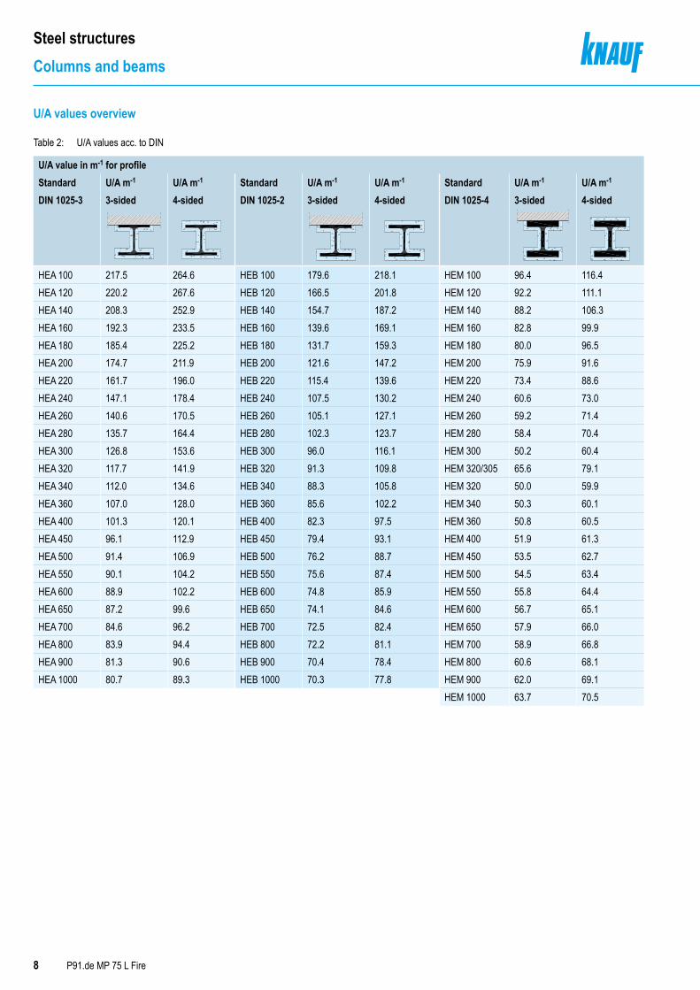
Table 2: U/A values acc. to DIN
U/A value in m-1 for profileStandard U/A m-1 U/A m-1 Standard U/A m-1 U/A m-1 Standard U/A m-1 U/A m-1
DIN 1025-3 3-sided 4-sided DIN 1025-2 3-sided 4-sided DIN 1025-4 3-sided 4-sided
HEA 100 217.5 264.6 HEB 100 179.6 218.1 HEM 100 96.4 116.4HEA 120 220.2 267.6 HEB 120 166.5 201.8 HEM 120 92.2 111.1HEA 140 208.3 252.9 HEB 140 154.7 187.2 HEM 140 88.2 106.3HEA 160 192.3 233.5 HEB 160 139.6 169.1 HEM 160 82.8 99.9HEA 180 185.4 225.2 HEB 180 131.7 159.3 HEM 180 80.0 96.5HEA 200 174.7 211.9 HEB 200 121.6 147.2 HEM 200 75.9 91.6HEA 220 161.7 196.0 HEB 220 115.4 139.6 HEM 220 73.4 88.6HEA 240 147.1 178.4 HEB 240 107.5 130.2 HEM 240 60.6 73.0HEA 260 140.6 170.5 HEB 260 105.1 127.1 HEM 260 59.2 71.4HEA 280 135.7 164.4 HEB 280 102.3 123.7 HEM 280 58.4 70.4HEA 300 126.8 153.6 HEB 300 96.0 116.1 HEM 300 50.2 60.4HEA 320 117.7 141.9 HEB 320 91.3 109.8 HEM 320/305 65.6 79.1HEA 340 112.0 134.6 HEB 340 88.3 105.8 HEM 320 50.0 59.9HEA 360 107.0 128.0 HEB 360 85.6 102.2 HEM 340 50.3 60.1HEA 400 101.3 120.1 HEB 400 82.3 97.5 HEM 360 50.8 60.5HEA 450 96.1 112.9 HEB 450 79.4 93.1 HEM 400 51.9 61.3HEA 500 91.4 106.9 HEB 500 76.2 88.7 HEM 450 53.5 62.7HEA 550 90.1 104.2 HEB 550 75.6 87.4 HEM 500 54.5 63.4HEA 600 88.9 102.2 HEB 600 74.8 85.9 HEM 550 55.8 64.4HEA 650 87.2 99.6 HEB 650 74.1 84.6 HEM 600 56.7 65.1HEA 700 84.6 96.2 HEB 700 72.5 82.4 HEM 650 57.9 66.0HEA 800 83.9 94.4 HEB 800 72.2 81.1 HEM 700 58.9 66.8HEA 900 81.3 90.6 HEB 900 70.4 78.4 HEM 800 60.6 68.1HEA 1000 80.7 89.3 HEB 1000 70.3 77.8 HEM 900 62.0 69.1
HEM 1000 63.7 70.5
9P91.de MP 75 L Fire
Steel structuresColumns and beams
U/A values overview
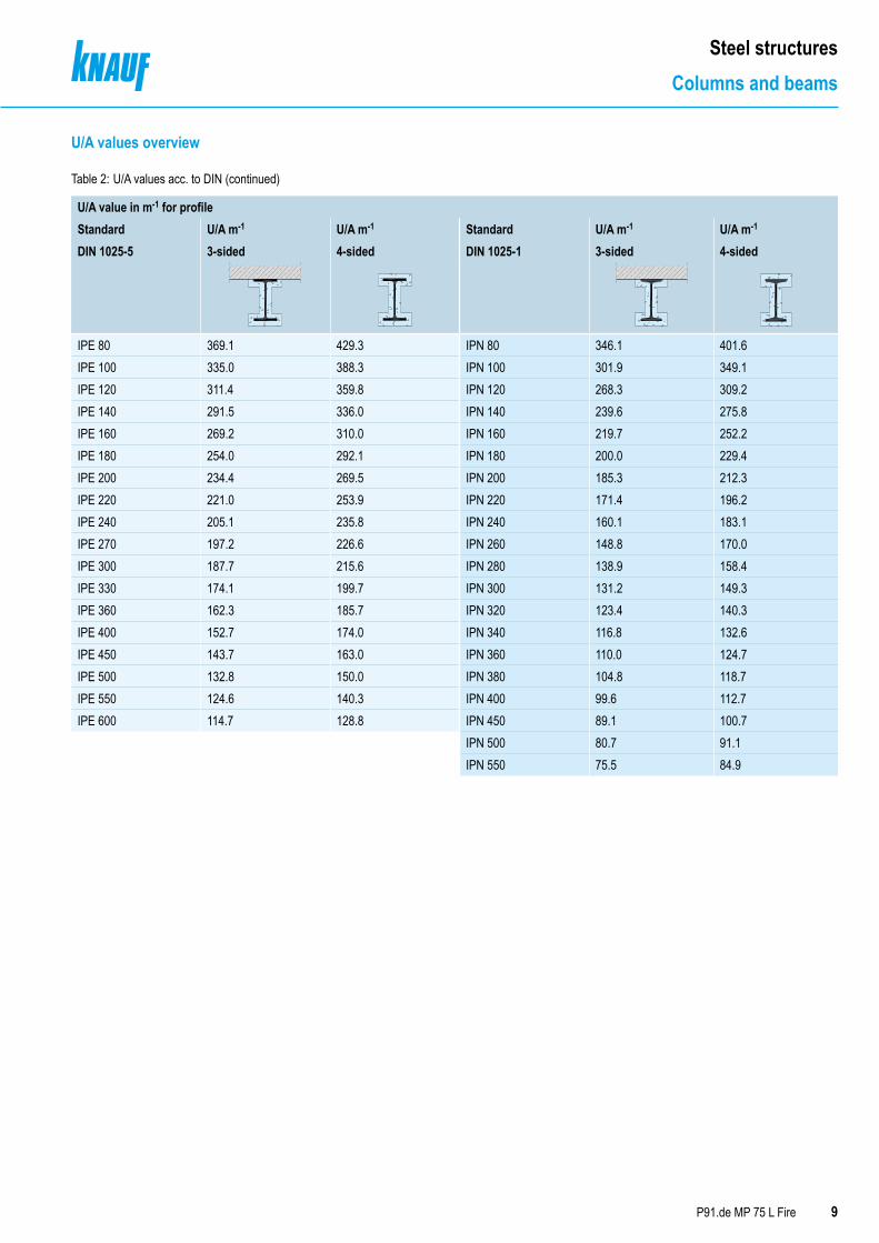
Table 2: U/A values acc. to DIN (continued)
U/A value in m-1 for profileStandard U/A m-1 U/A m-1 Standard U/A m-1 U/A m-1
DIN 1025-5 3-sided 4-sided DIN 1025-1 3-sided 4-sided
IPE 80 369.1 429.3 IPN 80 346.1 401.6IPE 100 335.0 388.3 IPN 100 301.9 349.1IPE 120 311.4 359.8 IPN 120 268.3 309.2IPE 140 291.5 336.0 IPN 140 239.6 275.8IPE 160 269.2 310.0 IPN 160 219.7 252.2IPE 180 254.0 292.1 IPN 180 200.0 229.4IPE 200 234.4 269.5 IPN 200 185.3 212.3IPE 220 221.0 253.9 IPN 220 171.4 196.2IPE 240 205.1 235.8 IPN 240 160.1 183.1IPE 270 197.2 226.6 IPN 260 148.8 170.0IPE 300 187.7 215.6 IPN 280 138.9 158.4IPE 330 174.1 199.7 IPN 300 131.2 149.3IPE 360 162.3 185.7 IPN 320 123.4 140.3IPE 400 152.7 174.0 IPN 340 116.8 132.6IPE 450 143.7 163.0 IPN 360 110.0 124.7IPE 500 132.8 150.0 IPN 380 104.8 118.7IPE 550 124.6 140.3 IPN 400 99.6 112.7IPE 600 114.7 128.8 IPN 450 89.1 100.7
IPN 500 80.7 91.1IPN 550 75.5 84.9
10 P91.de MP 75 L Fire
Steel structuresColumns and beams
U/A values overview
Table 2: U/A values acc. to DIN (continued)
U/A value in m-1 for profileStandard U/A m-1 U/A m-1 Standard U/A m-1 U/A m-1
DIN 1026-2 3-sided 4-sided DIN 1026-1 3-sided 4-sided
UPE 80 290.1 339.6 U 30 x 15 398.2 466.1UPE 100 277.6 321.6 U 30 259.2 319.9UPE 120 259.7 298.7 U 40 x 20 333.3 388.0UPE 140 247.3 282.6 U 40 264.1 320.5UPE 160 234.6 266.8 U 50 x 25 317.1 367.9UPE 180 224.7 254.6 U 50 272.5 325.8UPE 200 212.8 240.3 U 60 286.4 332.8UPE 220 197.9 223.0 U 65 255.8 302.3UPE 240 187.8 211.2 U 80 242.7 283.6UPE 270 177.9 199.1 U 100 238.5 275.6UPE 300 153.4 171.0 U 120 222.9 255.3UPE 330 138.3 153.8 U 140 210.3 239.7UPE 360 129.8 143.9 U 160 200.4 227.5UPE 400 120.0 132.5 U 180 193.2 218.2
U 200 182.0 205.3U 220 170.6 192.0U 240 163.1 183.2U 260 154.0 172.7U 280 149.2 167.0U 300 145.8 163.0U 320 116.4 129.6U 350 122.9 135.8U 380 125.4 138.1U 400 116.9 129.0
11P91.de MP 75 L Fire
Steel structuresColumns and beams
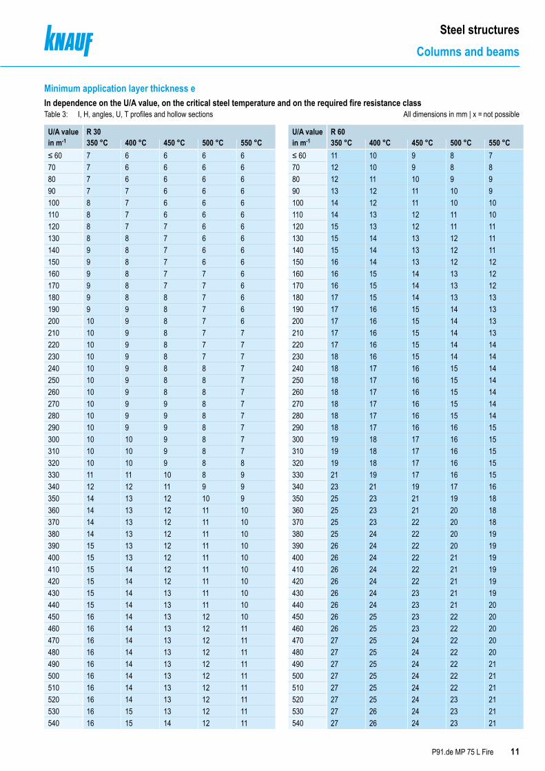
Minimum application layer thickness eIn dependence on the U/A value, on the critical steel temperature and on the required fire resistance classTable 3: I, H, angles, U, T profiles and hollow sections All dimensions in mm | x = not possible
U/A valuein m-1
R 30 U/A valuein m-1
R 60350 °C 400 °C 450 °C 500 °C 550 °C 350 °C 400 °C 450 °C 500 °C 550 °C
≤ 60 7 6 6 6 6 ≤ 60 11 10 9 8 770 7 6 6 6 6 70 12 10 9 8 880 7 6 6 6 6 80 12 11 10 9 990 7 7 6 6 6 90 13 12 11 10 9100 8 7 6 6 6 100 14 12 11 10 10110 8 7 6 6 6 110 14 13 12 11 10120 8 7 7 6 6 120 15 13 12 11 11130 8 8 7 6 6 130 15 14 13 12 11140 9 8 7 6 6 140 15 14 13 12 11150 9 8 7 6 6 150 16 14 13 12 12160 9 8 7 7 6 160 16 15 14 13 12170 9 8 7 7 6 170 16 15 14 13 12180 9 8 8 7 6 180 17 15 14 13 13190 9 9 8 7 6 190 17 16 15 14 13200 10 9 8 7 6 200 17 16 15 14 13210 10 9 8 7 7 210 17 16 15 14 13220 10 9 8 7 7 220 17 16 15 14 14230 10 9 8 7 7 230 18 16 15 14 14240 10 9 8 8 7 240 18 17 16 15 14250 10 9 8 8 7 250 18 17 16 15 14260 10 9 8 8 7 260 18 17 16 15 14270 10 9 9 8 7 270 18 17 16 15 14280 10 9 9 8 7 280 18 17 16 15 14290 10 9 9 8 7 290 18 17 16 16 15300 10 10 9 8 7 300 19 18 17 16 15310 10 10 9 8 7 310 19 18 17 16 15320 10 10 9 8 8 320 19 18 17 16 15330 11 11 10 8 9 330 21 19 17 16 15340 12 12 11 9 9 340 23 21 19 17 16350 14 13 12 10 9 350 25 23 21 19 18360 14 13 12 11 10 360 25 23 21 20 18370 14 13 12 11 10 370 25 23 22 20 18380 14 13 12 11 10 380 25 24 22 20 19390 15 13 12 11 10 390 26 24 22 20 19400 15 13 12 11 10 400 26 24 22 21 19410 15 14 12 11 10 410 26 24 22 21 19420 15 14 12 11 10 420 26 24 22 21 19430 15 14 13 11 10 430 26 24 23 21 19440 15 14 13 11 10 440 26 24 23 21 20450 16 14 13 12 10 450 26 25 23 22 20460 16 14 13 12 11 460 26 25 23 22 20470 16 14 13 12 11 470 27 25 24 22 20480 16 14 13 12 11 480 27 25 24 22 20490 16 14 13 12 11 490 27 25 24 22 21500 16 14 13 12 11 500 27 25 24 22 21510 16 14 13 12 11 510 27 25 24 22 21520 16 14 13 12 11 520 27 25 24 23 21530 16 15 13 12 11 530 27 26 24 23 21540 16 15 14 12 11 540 27 26 24 23 21

Minimum application layer thickness eTable 3: I, H, angles, U, T profiles and hollow sections (continued) All dimensions in mm | x = not possible
U/A value in m-1
R 90 U/A value in m-1
R 120350 °C 400 °C 450 °C 500 °C 550 °C 350 °C 400 °C 450 °C 500 °C 550 °C
≤ 60 16 14 13 12 11 ≤ 60 21 19 17 15 1470 17 15 13 12 11 70 22 19 18 16 1580 18 16 15 13 12 80 23 21 19 18 1690 19 17 15 14 13 90 24 22 20 19 17100 19 18 16 15 14 100 25 23 21 20 18110 20 19 17 16 15 110 26 23 22 21 19120 21 19 18 16 15 120 27 24 23 22 20130 21 20 18 17 16 130 28 25 24 23 21140 22 20 19 18 16 140 29 26 25 23 22150 23 21 20 18 17 150 29 27 26 24 23160 23 21 20 19 18 160 30 27 26 25 23170 23 22 20 19 18 170 30 28 27 25 24180 24 22 21 20 18 180 31 29 28 26 25190 24 23 21 20 18 190 31 29 28 27 25200 24 23 22 20 19 200 32 30 29 27 26210 25 23 22 21 19 210 34 30 29 28 26220 25 24 22 21 20 220 36 31 29 28 27230 25 24 23 21 20 230 x 31 30 28 27240 26 24 23 22 20 240 x 31 30 29 28250 26 24 23 22 21 250 x 32 31 29 28260 26 25 23 22 21 260 x 32 31 30 28270 26 25 24 23 21 270 x 34 31 30 29280 26 25 24 23 22 280 x 36 32 30 29290 27 25 24 23 22 290 x x 32 31 29300 27 26 24 23 22 300 x x 32 31 30310 27 26 25 24 22 310 x x 33 31 30320 27 26 25 24 23 320 x x 35 31 30330 28 27 26 25 23 330 x x 35 32 31340 30 29 27 26 24 340 x x 35 33 32350 32 31 29 28 26 350 x x 35 34 33360 32 31 29 28 27 360 x x 36 34 33370 33 31 30 28 27 370 x x x 34 33380 33 31 30 28 27 380 x x x 34 33390 33 31 30 28 27 390 x x x 35 33400 33 31 30 29 27 400 x x x 35 33410 33 32 30 29 27 410 x x x 35 33420 33 32 30 29 28 420 x x x 35 34430 33 32 30 29 28 430 x x x 35 34440 33 32 30 29 28 440 x x x 35 34450 33 32 31 29 28 450 x x x 35 34460 33 32 31 29 28 460 x x x 36 34470 33 32 31 30 28 470 x x x x 34480 33 32 31 30 28 480 x x x x 34490 33 32 31 30 28 490 x x x x 34500 33 32 31 30 28 500 x x x x 34510 34 32 31 30 29 510 x x x x 35520 34 32 31 30 29 520 x x x x 35530 34 32 31 30 29 530 x x x x 35540 34 33 31 30 29 540 x x x x 35The minimum application layer thickness for hollow sections must be increased by 25 %. Do not use if an application layer thickness exceeding 36 mm is required.
12 P91.de MP 75 L Fire
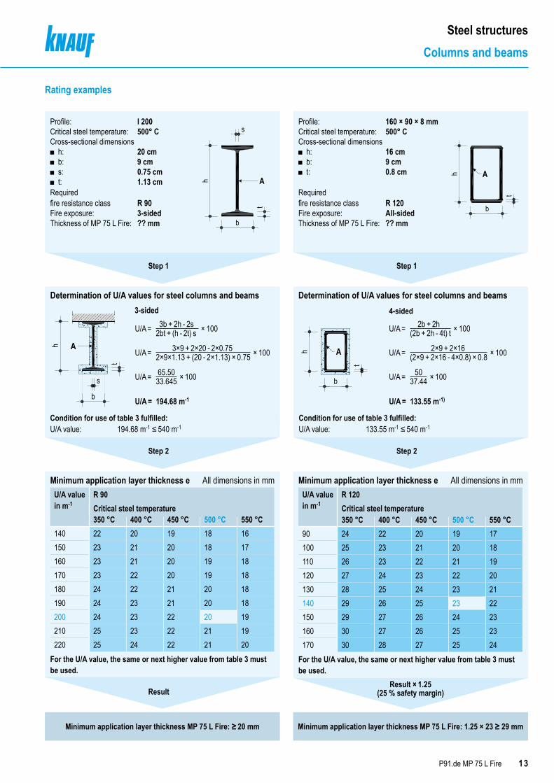
Steel structuresColumns and beams
h A
b
s
t
b
h
tA
Determination of U/A values for steel columns and beams Determination of U/A values for steel columns and beams
b
h
tA
Determination of U/A values for steel columns and beams
Condition for use of table 3 fulfilled:U/A value: 194.68 m-1 ≤ 540 m-1
Condition for use of table 3 fulfilled:U/A value: 133.55 m-1 ≤ 540 m-1
13P91.de MP 75 L Fire
Steel structuresColumns and beams
Profile: 160 × 90 × 8 mmCritical steel temperature: 500° CCross-sectional dimensions
■ h: 16 cm ■ b: 9 cm ■ t: 0.8 cm
Requiredfire resistance class R 120Fire exposure: All-sidedThickness of MP 75 L Fire: ?? mm
Ah
b
t
3-sided 4-sided
Minimum application layer thickness e All dimensions in mmU/A value in m-1
R 90Critical steel temperature350 °C 400 °C 450 °C 500 °C 550 °C
140 22 20 19 18 16150 23 21 20 18 17160 23 21 20 19 18170 23 22 20 19 18180 24 22 21 20 18190 24 23 21 20 18200 24 23 22 20 19210 25 23 22 21 19220 25 24 22 21 20
For the U/A value, the same or next higher value from table 3 must be used.
Minimum application layer thickness e All dimensions in mmU/A value in m-1
R 120Critical steel temperature350 °C 400 °C 450 °C 500 °C 550 °C
90 24 22 20 19 17100 25 23 21 20 18110 26 23 22 21 19120 27 24 23 22 20130 28 25 24 23 21140 29 26 25 23 22150 29 27 26 24 23160 30 27 26 25 23170 30 28 27 25 24
For the U/A value, the same or next higher value from table 3 must be used.
Step 1 Step 1
Step 2 Step 2
Minimum application layer thickness MP 75 L Fire: ≥ 20 mm Minimum application layer thickness MP 75 L Fire: 1.25 × 23 ≥ 29 mm
ResultResult × 1.25
3×9 + 2×20 - 2×0.75 2×9 + 2×16
65.50 50
3b + 2h - 2s 2b + 2h
2×9×1.13 + (20 - 2×1.13) × 0.75 (2×9 + 2×16 - 4×0.8) × 0.8
33.645 37.44
2bt + (h - 2t) s (2b + 2h - 4t) t× 100 × 100
× 100 × 100
× 100 × 100
133.55 m-1)194.68 m-1
U/A = U/A =
U/A = U/A =
U/A = U/A =
U/A = U/A =
Rating examples
Profile: I 200Critical steel temperature: 500° CCross-sectional dimensions
■ h: 20 cm ■ b: 9 cm ■ s: 0.75 cm ■ t: 1.13 cm
Requiredfire resistance class R 90Fire exposure: 3-sidedThickness of MP 75 L Fire: ?? mm
s
b
Ah
t
(25 % safety margin)
14 P91.de MP 75 L Fire
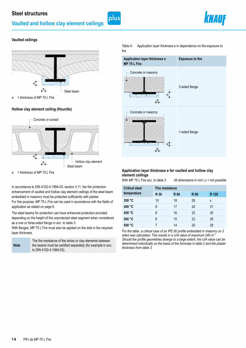
Steel structuresVaulted and hollow clay element ceilings
Vaulted ceilingse
eSteel beam
e = thickness of MP 75 L Fire
Hollow clay element ceiling (Hourdis)
e
e
Concrete or screed
Hollow clay elementSteel beam
e = thickness of MP 75 L Fire
Table 4: Application layer thickness e in dependence on the exposure to fire
Application layer thickness e MP 75 L Fire
Exposure to fire
Concrete or masonry
e
e
3-sided flange
e
e
Concrete or masonry
1-sided flange
Application layer thickness e for vaulted and hollow clay element ceilingsWith MP 75 L Fire acc. to table 3 All dimensions in mm | x = not possible
Critical steel temperature
Fire resistance R 30 R 60 R 90 R 120
350 °C 10 18 26 x400 °C 9 17 24 31450 °C 8 16 23 30500 °C 8 15 22 29550 °C 7 14 20 28
For the table, a critical case of an IPE 80 profile embedded in masonry on 3 sides was calculated. This results in a U/A value of maximum 240 m-1.Should the profile geometries diverge to a large extent, the U/A value can be determined individually on the basis of the formulae in table 2 and the plaster thickness from table 3.
In accordance to DIN 4102-4:1994-03, section 3.11, the fire protection enhancement of vaulted and hollow clay element ceilings of the steel beam embedded in masonry must be protected sufficiently with plaster. For this purpose, MP 75 L Fire can be used in accordance with the fields of application as stated on page 6.The steel beams for protection can have enhanced protection provided depending on the height of the unprotected steel segment when considered as a one or three-sided flange in acc. to table 3. With flanges, MP 75 L Fire must also be applied on the side in the required layer thickness.
NoteThe fire resistance of the bricks or clay elements between the beams must be certified separately (for example in acc. to DIN 4102-4:1994-03).
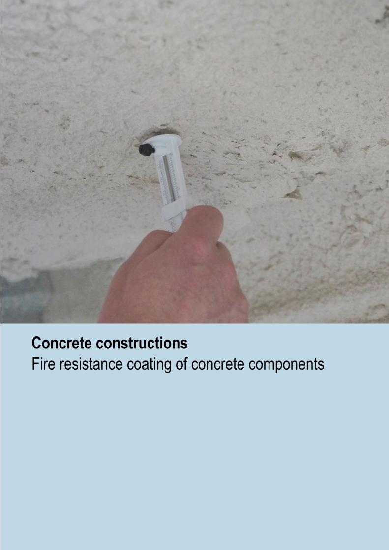
Concrete constructionsFire resistance coating of concrete components

16
P91.de MP 75 L Fire
Concrete constructionsColumns and beams
Field of applicationConcrete beams and columns exposed on multiple sidesFor a concrete density in a range of 2025 kg/m3 to 2740 kg/m3 and a column / beam width of at least 150 mm, concrete strength class at least C30/37.
■ Lightweight aggregate concrete, e.g. pumice concrete acc. to EN 1520 or aerated concrete acc. to DIN 4223-1
■ Normal-weight concrete acc. to EN 206-1 / DIN 1045-2 of strength classes ≤ C80/95
■ Beams and columns with a width of at least 80 mm ■ Beams and columns exposed on one side ■ Applications acc. to DIN 4102-4
Concrete columnsexist. a = existing concrete cover (distance between centres)exist. b = larger existing column widthexist. d = smaller existing column width or diametere = thickness MP 75 L Fire
Concrete beamsexist. a = existing concrete slab (distance between centres)exist. asd = existing concrete cover horizontal (distance between centres)exist. b = existing beam width in the height of the centre of gravity of the tensile area reinforcemente = thickness MP 75 L Fire
e
exist
. a
exist. b
exist. asd exist. b
e
exist
. a
exist. d
exist
. b ≥
exist
. de
exist
. a
exist. deexist. a
Procedure1. Observe the fields of application.2. Determine the required concrete thickness (req. a or req. b and req. d)
acc to EN 1992-1-2, section 5.3. Determine the existing concrete thickness (exist. a and exist. b or
exist. d) and derive the decisive (maximum) missing concrete thickness. 4. Read off the minimum plaster layer thickness e for MP 75 L Fire in
accordance with the missing concrete thickness from the tables on the following pages.
See page 19 for rating example.
Technical fire resistance assessed acc. to GS 3.2/15-094-1
■ Prior consultation acc. to note on page 4 is recommended
The rating of the plaster thickness of MP 75 L Fire required for fire resistance purposes on concrete components is in accordance with the tables on the following pages and depends on
■ Constructional component and loading ■ Required fire resistance class according to building authority requirements ■ Demands on the concrete thickness acc. to DIN EN 1992-1-2, section 5 for the necessary fire resistance class
■ Existing concrete thickness ■ Equivalent concrete thickness of the ETA-11/0229

17P91.de MP 75 L Fire
Concrete constructionsColumns and beams
Minimum application layer thickness e In dependence on the fire resistance class and missing concrete thicknessDiagram 1
Diagram 2
R 30
Minim
um ap
plica
tion l
ayer
thick
ness
MP
75 L
Fire i
n mm 19 ≤ 33
18 ≤ 3217 ≤ 3016 ≤ 2815 ≤ 2614 ≤ 2513 ≤ 2312 ≤ 2111 ≤ 2010 ≤ 189 ≤ 168 ≤ 147 ≤ 13
11 12 13 14 15 16 17 18 19 20 21 22 23 24 25 26 27 28 29 30 31 32 33Missing concrete thickness in mm
R 60
Minim
um ap
plica
tion l
ayer
thick
ness
MP
75 L
Fire i
n mm 19 ≤ 46
18 ≤ 4517 ≤ 4316 ≤ 4115 ≤ 3914 ≤ 3813 ≤ 3612 ≤ 3411 ≤ 3310 ≤ 319 ≤ 298 ≤ 277 ≤ 26
25 26 27 28 29 30 31 32 33 34 35 36 37 38 39 40 41 42 43 44 45 46 47Missing concrete thickness in mm
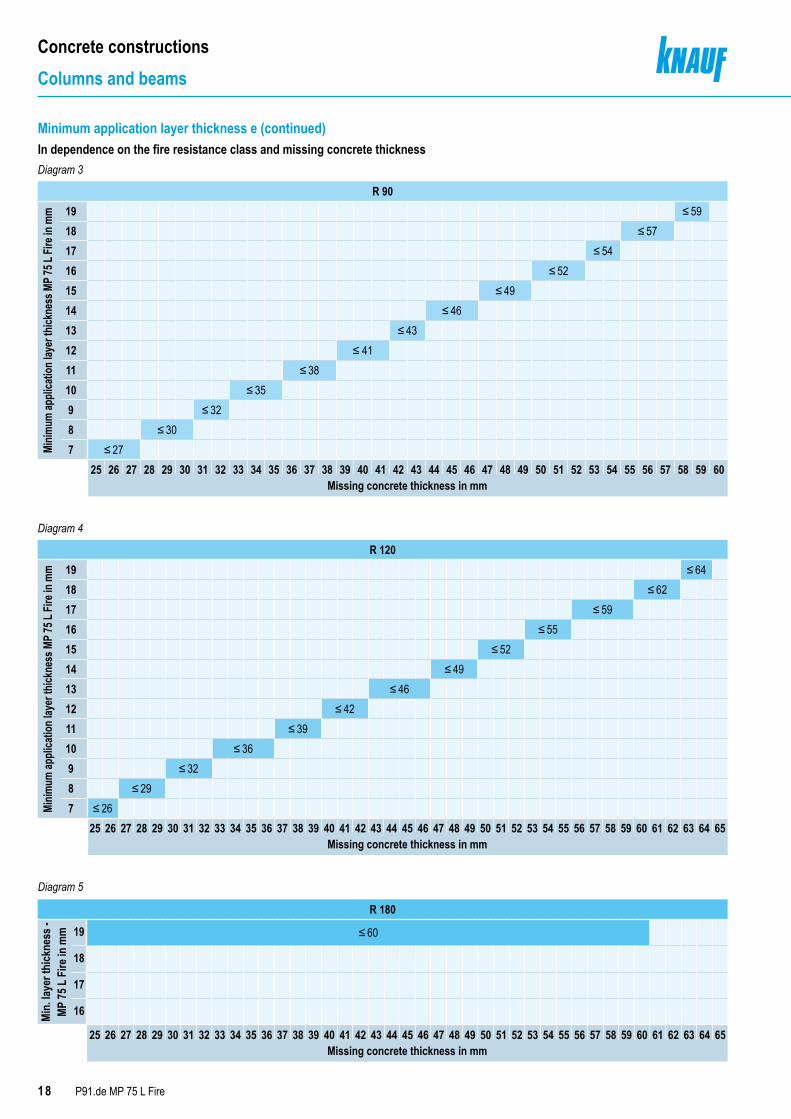
18 P91.de MP 75 L Fire
Concrete constructionsColumns and beams
Diagram 3
Diagram 4
Diagram 5
R 90
Minim
um ap
plica
tion l
ayer
thick
ness
MP 7
5 L Fi
re in
mm 19 ≤ 59
18 ≤ 5717 ≤ 5416 ≤ 5215 ≤ 4914 ≤ 4613 ≤ 4312 ≤ 4111 ≤ 3810 ≤ 359 ≤ 328 ≤ 307 ≤ 27
25 26 27 28 29 30 31 32 33 34 35 36 37 38 39 40 41 42 43 44 45 46 47 48 49 50 51 52 53 54 55 56 57 58 59 60Missing concrete thickness in mm
R 120
Minim
um ap
plica
tion l
ayer
thick
ness
MP
75 L
Fire i
n mm 19 ≤ 64
18 ≤ 6217 ≤ 5916 ≤ 5515 ≤ 5214 ≤ 4913 ≤ 4612 ≤ 4211 ≤ 3910 ≤ 369 ≤ 328 ≤ 297 ≤ 26
25 26 27 28 29 30 31 32 33 34 35 36 37 38 39 40 41 42 43 44 45 46 47 48 49 50 51 52 53 54 55 56 57 58 59 60 61 62 63 64 65Missing concrete thickness in mm
R 180
Min.
laye
r thi
ckne
ss -
MP 75
L F
ire in
mm 19 ≤ 60
18
17
16
25 26 27 28 29 30 31 32 33 34 35 36 37 38 39 40 41 42 43 44 45 46 47 48 49 50 51 52 53 54 55 56 57 58 59 60 61 62 63 64 65Missing concrete thickness in mm
Minimum application layer thickness e (continued)In dependence on the fire resistance class and missing concrete thickness
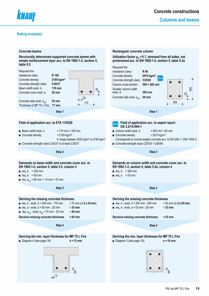
Rectangular concrete columnUtilisation factor μfi = 0.7, stressed from all sides, not prestressed acc. to EN 1992-1-2, section 5, table 5.2a
Required fire resistance class: R 90Concrete density: 2010 kg/m³Concrete strength class: C25/30Column cross-section: 300 × 400 mmSmaller column width exist. d:
300 mm
Concrete slab exist. asd: 20 mm
Thickness of MP 75 L Fire: ?? mm
400
300
20
19P91.de MP 75 L Fire
Concrete constructionsColumns and beams
Concrete beamsStructurally determined supported concrete beams with simple reinforcement layer acc. to EN 1992-1-2, section 5, table 5.5
Required fire resistance class: R 120Concrete density: 2100 kg/m³Concrete strength class: C30/37Beam width exist. b: 170 mmConcrete cover exist. a: 25 mm
Concrete slab exist. asd: 25 mmThickness of MP 75 L Fire: ?? mm
25
17025
Step 1 Step 1
Field of application acc. to ETA 11/0229
■ Beam width exist. b = 170 mm > 150 mm ■ Concrete density = 2100 kg/m3 in range between 2025 kg/m3 to 2740 kg/m3
■ Concrete strength class C30/37 is at least C30/37
Demands on beam width and concrete cover acc. to EN 1992-1-2, section 5, table 5.5, column 3
■ req. b = 240 mm ■ req. a = 60 mm ■ req. asd = 60 mm + 10 mm = 70 mm
Demands on column width and concrete cover acc. to EN 1992-1-2, section 5, table 5.2a, column 4
■ req. d = 350 mm ■ req. a = 53 mm
Deriving the missing concrete thickness ■ req. b - exist. b = 240 mm - 170 mm = 70 mm (is 2 x 35 mm) ■ req. a - exist. a = 60 mm - 25 mm = 35 mm ■ req. asd - exist. asd = 70 mm - 25 mm = 45 mm
Decisive missing concrete thickness = 45 mm
Deriving the missing concrete thickness ■ req. d - exist. d = 350 mm - 300 mm = 50 mm (is 2 x 25 mm) ■ req. a - exist. a = 53 mm - 20 mm = 33 mm
Decisive missing concrete thickness = 33 mm
Deriving the min. layer thickness for MP 75 L Fire ■ Diagram 4 (see page 18): e = 13 mm
13
13
Deriving the min. layer thickness for MP 75 L Fire ■ Diagram 3 (see page 18): e = 10 mm
10
Step 2 Step 2
Step 3 Step 3
Step 4Step 4
Rating examples
■ Column width exist. b = 300 mm > 80 mm ■ Concrete density = 2010 kg/m3 Corresponds to normal-weight concrete acc. to EN 206-1 / DIN 1045-2
■ Concrete strength class C25/30 < C80/95
Field of application acc. to expert report GS 3.2/15-094-1
20 P91.de MP 75 L Fire
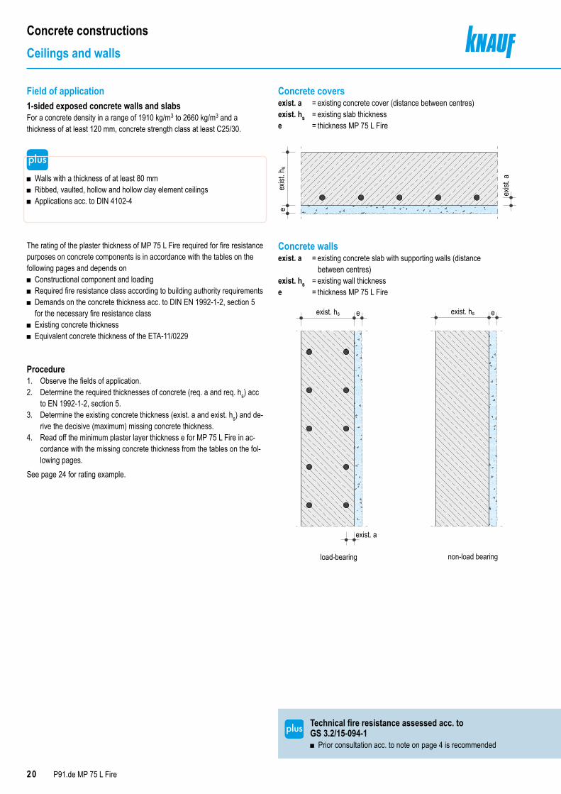
Concrete constructionsCeilings and walls
Concrete coversexist. a = existing concrete cover (distance between centres)exist. hs = existing slab thicknesse = thickness MP 75 L Fire
eexist
. hs
exist
. a
Concrete wallsexist. a = existing concrete slab with supporting walls (distance between centres)exist. hs = existing wall thicknesse = thickness MP 75 L Fire
exist. hs e
load-bearing
exist. a
exist. hs e
non-load bearing
Procedure1. Observe the fields of application.2. Determine the required thicknesses of concrete (req. a and req. hs) acc
to EN 1992-1-2, section 5.3. Determine the existing concrete thickness (exist. a and exist. hs) and de-
rive the decisive (maximum) missing concrete thickness.4. Read off the minimum plaster layer thickness e for MP 75 L Fire in ac-
cordance with the missing concrete thickness from the tables on the fol-lowing pages.
See page 24 for rating example.
Field of application1-sided exposed concrete walls and slabsFor a concrete density in a range of 1910 kg/m3 to 2660 kg/m3 and a thickness of at least 120 mm, concrete strength class at least C25/30.
■ Walls with a thickness of at least 80 mm ■ Ribbed, vaulted, hollow and hollow clay element ceilings ■ Applications acc. to DIN 4102-4
exist. hs e
load-bearing
exist. a
exist. hs e
non-load bearing
The rating of the plaster thickness of MP 75 L Fire required for fire resistance purposes on concrete components is in accordance with the tables on the following pages and depends on
■ Constructional component and loading ■ Required fire resistance class according to building authority requirements ■ Demands on the concrete thickness acc. to DIN EN 1992-1-2, section 5 for the necessary fire resistance class
■ Existing concrete thickness ■ Equivalent concrete thickness of the ETA-11/0229
Technical fire resistance assessed acc. to GS 3.2/15-094-1
■ Prior consultation acc. to note on page 4 is recommended
21P91.de MP 75 L Fire
Concrete constructionsCeilings and walls
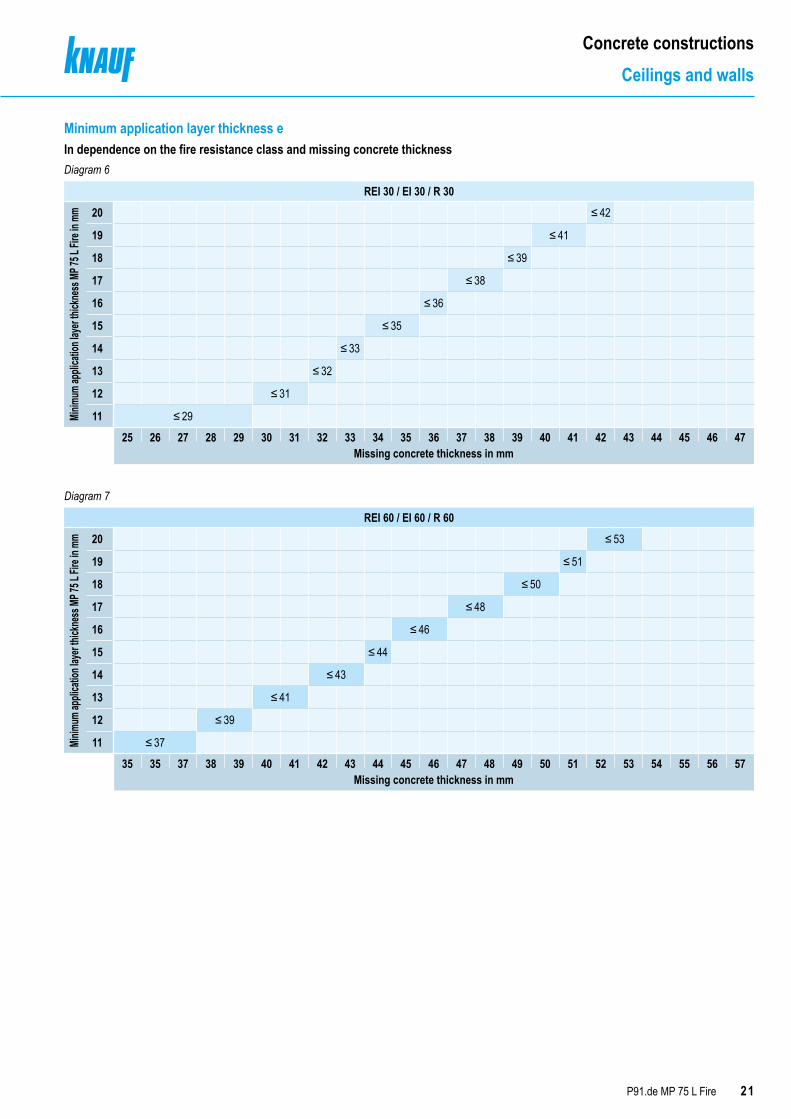
Minimum application layer thickness e In dependence on the fire resistance class and missing concrete thicknessDiagram 6
Diagram 7
REI 30 / EI 30 / R 30
Minim
um ap
plica
tion l
ayer
thick
ness
MP 7
5 L Fi
re in
mm 20 ≤ 42
19 ≤ 41
18 ≤ 39
17 ≤ 38
16 ≤ 36
15 ≤ 35
14 ≤ 33
13 ≤ 32
12 ≤ 31
11 ≤ 29
25 26 27 28 29 30 31 32 33 34 35 36 37 38 39 40 41 42 43 44 45 46 47Missing concrete thickness in mm
REI 60 / EI 60 / R 60
Minim
um ap
plica
tion l
ayer
thick
ness
MP 7
5 L Fi
re in
mm 20 ≤ 53
19 ≤ 51
18 ≤ 50
17 ≤ 48
16 ≤ 46
15 ≤ 44
14 ≤ 43
13 ≤ 41
12 ≤ 39
11 ≤ 37
35 35 37 38 39 40 41 42 43 44 45 46 47 48 49 50 51 52 53 54 55 56 57Missing concrete thickness in mm

22 P91.de MP 75 L Fire
Concrete constructionsCeilings and walls
Diagram 8
Diagram 9
REI 90 / EI 90 / R 90
Minim
um ap
plica
tion l
ayer
thick
ness
MP 7
5 L Fi
re in
mm 20 ≤ 63
19 ≤ 61
18 ≤ 58
17 ≤ 56
16 ≤ 53
15 ≤ 51
14 ≤ 49
13 ≤ 46
12 ≤ 44
11 ≤ 41
40 41 42 43 44 45 46 47 48 49 50 51 52 53 54 55 56 57 58 59 60 61 62 63 64 65 66 67Missing concrete thickness in mm
REI 120 / EI 120 / R 120
Minim
um ap
plica
tion l
ayer
thick
ness
MP 7
5 L Fi
re in
mm 20 ≤ 67
19 ≤ 64
18 ≤ 61
17 ≤ 59
16 ≤ 56
15 ≤ 53
14 ≤ 50
13 ≤ 47
12 ≤ 44
11 ≤ 42
40 41 42 43 44 45 46 47 48 49 50 51 52 53 54 55 56 57 58 59 60 61 62 63 64 65 66 67Missing concrete thickness in mm
Minimum application layer thickness e (continued)In dependence on the fire resistance class and missing concrete thickness
23P91.de MP 75 L Fire
Concrete constructionsCeilings and walls
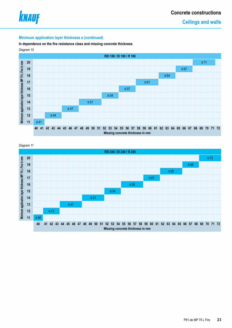
Diagram 10
Diagram 11
REI 180 / EI 180 / R 180
Minim
um ap
plica
tion l
ayer
thick
ness
MP 7
5 L Fi
re in
mm 20 ≤ 71
19 ≤ 67
18 ≤ 64
17 ≤ 61
16 ≤ 57
15 ≤ 54
14 ≤ 51
13 ≤ 47
12 ≤ 44
11 ≤ 41
40 41 42 43 44 45 46 47 48 49 50 51 52 53 54 55 56 57 58 59 60 61 62 63 64 65 66 67 68 69 70 71 72Missing concrete thickness in mm
REI 240 / EI 240 / R 240
Minim
um ap
plica
tion l
ayer
thick
ness
MP 7
5 L Fi
re in
mm 20 ≤ 72
19 ≤ 68
18 ≤ 65
17 ≤ 61
16 ≤ 58
15 ≤ 54
14 ≤ 51
13 ≤ 47
12 ≤ 43
11 ≤ 40
40 41 42 43 44 45 46 47 48 49 50 51 52 53 54 55 56 57 58 59 60 61 62 63 64 65 66 67 68 69 70 71 72Missing concrete thickness in mm
Minimum application layer thickness e (continued)In dependence on the fire resistance class and missing concrete thickness
24 P91.de MP 75 L Fire
Concrete constructionsCeilings and walls
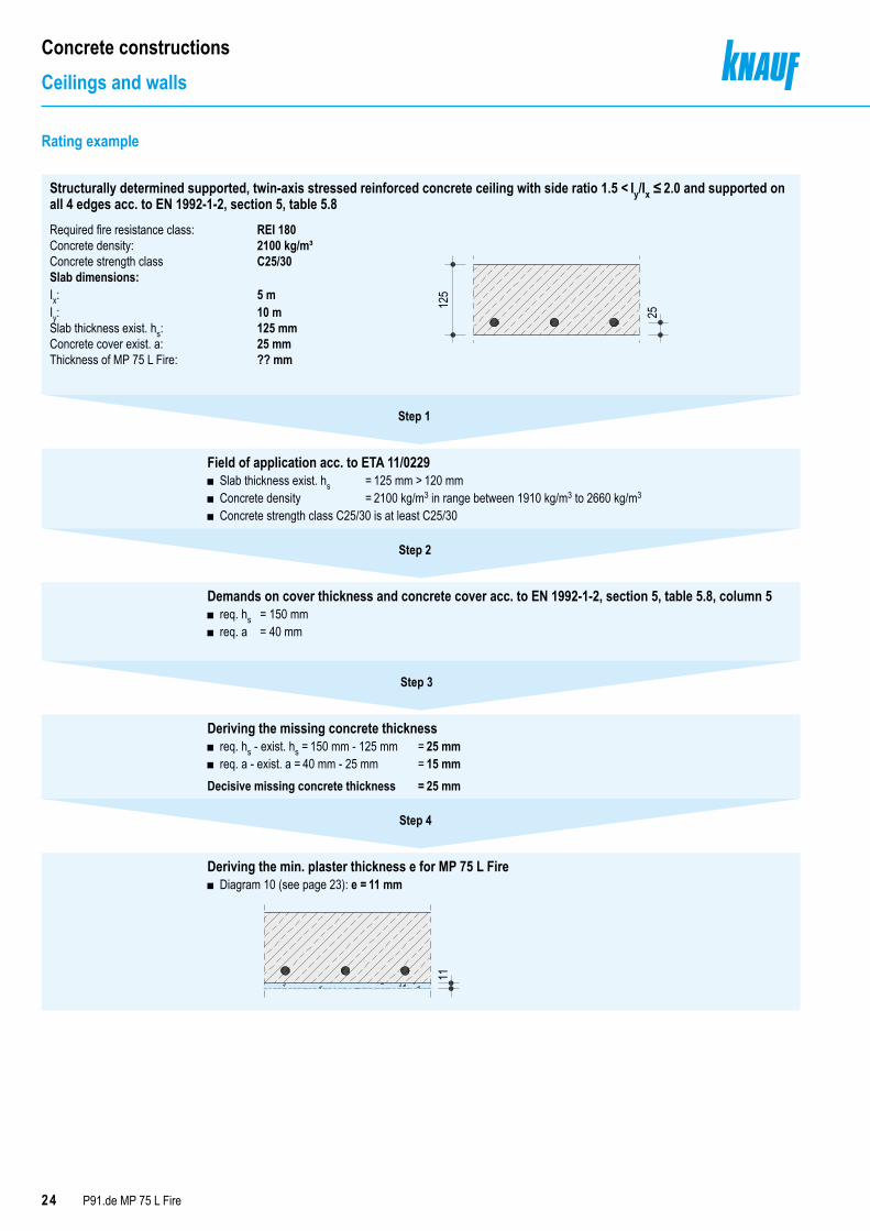
Structurally determined supported, twin-axis stressed reinforced concrete ceiling with side ratio 1.5 < Iy/Ix ≤ 2.0 and supported on all 4 edges acc. to EN 1992-1-2, section 5, table 5.8Required fire resistance class: REI 180Concrete density: 2100 kg/m³Concrete strength class C25/30Slab dimensions:Ix:Iy:
5 m10 m
Slab thickness exist. hs: 125 mmConcrete cover exist. a: 25 mmThickness of MP 75 L Fire: ?? mm
Step 1
Field of application acc. to ETA 11/0229 ■ Slab thickness exist. hs = 125 mm > 120 mm ■ Concrete density = 2100 kg/m3 in range between 1910 kg/m3 to 2660 kg/m3
■ Concrete strength class C25/30 is at least C25/30
Demands on cover thickness and concrete cover acc. to EN 1992-1-2, section 5, table 5.8, column 5 ■ req. hs = 150 mm ■ req. a = 40 mm
Deriving the missing concrete thickness ■ req. hs - exist. hs = 150 mm - 125 mm = 25 mm ■ req. a - exist. a = 40 mm - 25 mm = 15 mm
Decisive missing concrete thickness = 25 mm
Deriving the min. plaster thickness e for MP 75 L Fire ■ Diagram 10 (see page 23): e = 11 mm
Step 2
Step 3
Step 4
Rating example
11125
25
25P91.de MP 75 L Fire
Concrete constructionsRibbed and dropped ceilings
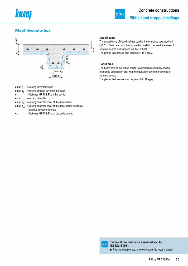
Ribbed / dropped ceilings
exist
. he
e
exist
. a
exist
. a
exist. b
exist. asd
h
b
b
h
exist. h = existing cover thicknessexist. ah = existing concete cover for the covereh = thickness MP 75 L Fire in flat sectionexist. b = existing rib widthexist. ab = existing concrete cover of the underbeamsexist. asd = existing concrete cover of the underbeams horizontal (distance between centres)eb = thickness MP 75 L Fire on the underbeams
UnderbeamsThe underbeams of ribbed ceilings can be fire resistance upgraded with MP 75 L Fire in acc. with the indicated equivalent concrete thicknesses for concrete beams and supports in ETA-11/0229.The plaster thicknesses from diagrams 1 to 5 apply.
Board areaThe board area of the ribbed ceiling is considered separately and fire resistance upgraded in acc. with the equivalent concrete thickness for concrete covers.The plaster thicknesses from diagrams 6 to 11 apply.
Technical fire resistance assessed acc. to GS 3.2/15-094-1
■ Prior consultation acc. to note on page 4 is recommended
26 P91.de MP 75 L Fire
Concrete constructionsRibbed and dropped ceilings
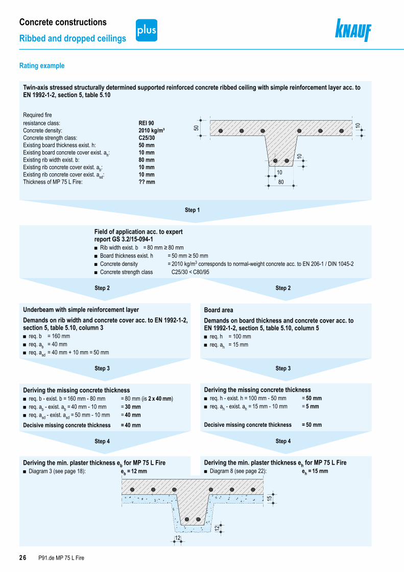
Twin-axis stressed structurally determined supported reinforced concrete ribbed ceiling with simple reinforcement layer acc. to EN 1992-1-2, section 5, table 5.10
Required fire resistance class: REI 90Concrete density: 2010 kg/m³Concrete strength class: C25/30Existing board thickness exist. h: 50 mmExisting board concrete cover exist. ah: 10 mmExisting rib width exist. b: 80 mmExisting rib concrete cover exist. ab: 10 mmExisting rib concrete cover exist. asd: 10 mmThickness of MP 75 L Fire: ?? mm
50
80
10
10
10
Step 1
Field of application acc. to expert report GS 3.2/15-094-1
■ Rib width exist. b = 80 mm ≥ 80 mm ■ Board thickness exist. h = 50 mm ≥ 50 mm ■ Concrete density = 2010 kg/m3 corresponds to normal-weight concrete acc. to EN 206-1 / DIN 1045-2 ■ Concrete strength class C25/30 < C80/95
Underbeam with simple reinforcement layerDemands on rib width and concrete cover acc. to EN 1992-1-2, section 5, table 5.10, column 3
■ req. b = 160 mm ■ req. ab = 40 mm ■ req. asd = 40 mm + 10 mm = 50 mm
Board areaDemands on board thickness and concrete cover acc. to EN 1992-1-2, section 5, table 5.10, column 5
■ req. h = 100 mm ■ req. ah = 15 mm
Deriving the missing concrete thickness ■ req. b - exist. b = 160 mm - 80 mm = 80 mm (is 2 x 40 mm) ■ req. ab - exist. ab = 40 mm - 10 mm = 30 mm ■ req. asd - exist. asd = 50 mm - 10 mm = 40 mm
Decisive missing concrete thickness = 40 mm
Deriving the missing concrete thickness ■ req. h - exist. h = 100 mm - 50 mm = 50 mm ■ req. ah - exist. ah = 15 mm - 10 mm = 5 mm
Decisive missing concrete thickness = 50 mm
Deriving the min. plaster thickness eb for MP 75 L Fire ■ Diagram 3 (see page 18): eb = 12 mm
Deriving the min. plaster thickness eh for MP 75 L Fire ■ Diagram 8 (see page 22): eh = 15 mm
Step 2 Step 2
Step 3 Step 3
Step 4 Step 4
15
12
12
Rating example
27P91.de MP 75 L Fire
Concrete constructionsReinforced concrete hollow ceilings
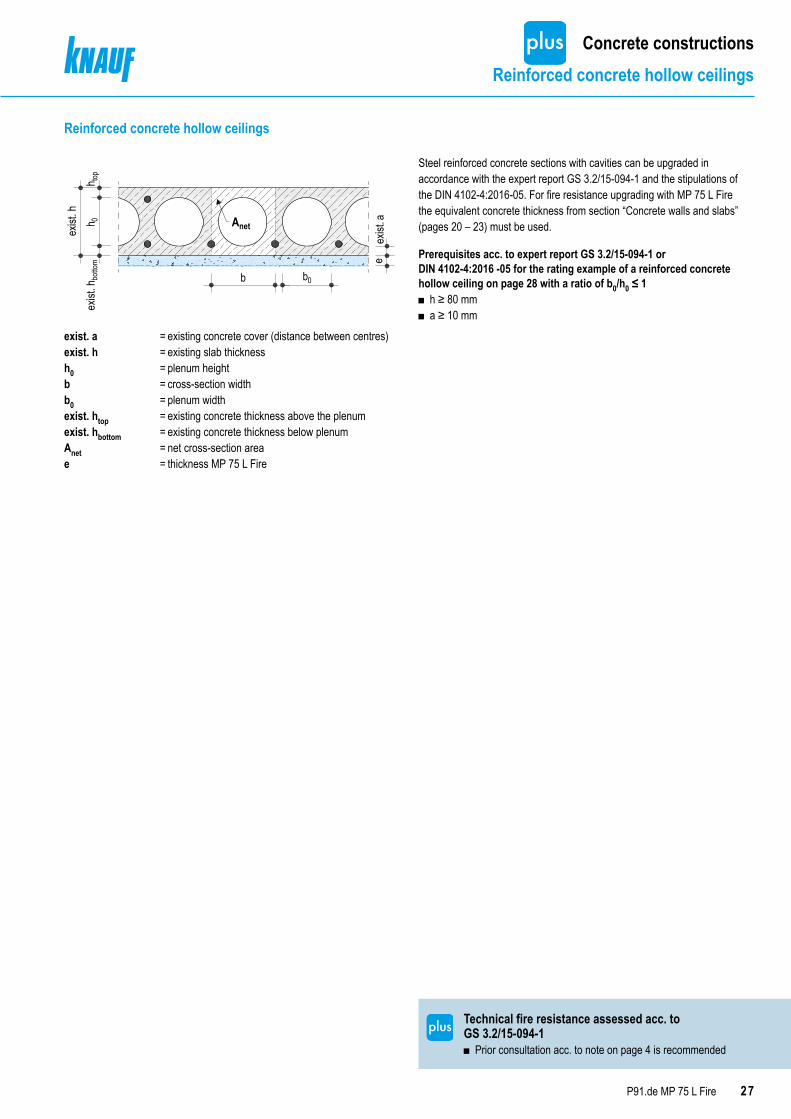
Reinforced concrete hollow ceilings
exist
. hbottom
h 0h to
p
exist
. h
b b0
eexist
. aAnet
exist. a = existing concrete cover (distance between centres)exist. h = existing slab thicknessh0 = plenum heightb = cross-section widthb0 = plenum widthexist. htop = existing concrete thickness above the plenumexist. hbottom = existing concrete thickness below plenumAnet = net cross-section areae = thickness MP 75 L Fire
Prerequisites acc. to expert report GS 3.2/15-094-1 or DIN 4102-4:2016 -05 for the rating example of a reinforced concrete hollow ceiling on page 28 with a ratio of b0/h0 ≤ 1
■ h ≥ 80 mm ■ a ≥ 10 mm
Steel reinforced concrete sections with cavities can be upgraded in accordance with the expert report GS 3.2/15-094-1 and the stipulations of the DIN 4102-4:2016-05. For fire resistance upgrading with MP 75 L Fire the equivalent concrete thickness from section “Concrete walls and slabs” (pages 20 – 23) must be used.
Technical fire resistance assessed acc. to GS 3.2/15-094-1
■ Prior consultation acc. to note on page 4 is recommended
28 P91.de MP 75 L Fire
Concrete constructionsReinforced concrete hollow ceilings
Step 1
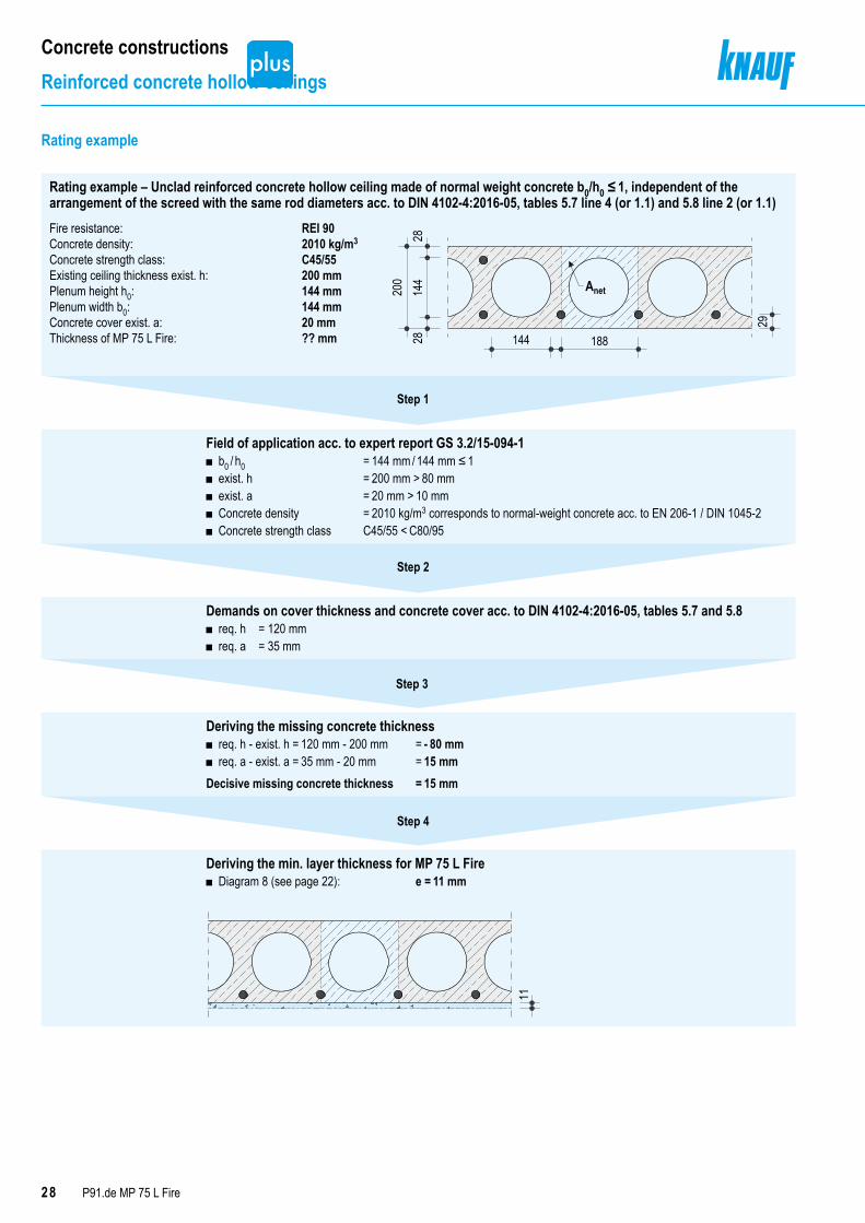
Field of application acc. to expert report GS 3.2/15-094-1 ■ b0 / h0 = 144 mm / 144 mm ≤ 1 ■ exist. h = 200 mm > 80 mm ■ exist. a = 20 mm > 10 mm ■ Concrete density = 2010 kg/m3 corresponds to normal-weight concrete acc. to EN 206-1 / DIN 1045-2 ■ Concrete strength class C45/55 < C80/95
Demands on cover thickness and concrete cover acc. to DIN 4102-4:2016-05, tables 5.7 and 5.8 ■ req. h = 120 mm ■ req. a = 35 mm
Deriving the missing concrete thickness ■ req. h - exist. h = 120 mm - 200 mm = - 80 mm ■ req. a - exist. a = 35 mm - 20 mm = 15 mm
Decisive missing concrete thickness = 15 mm
Deriving the min. layer thickness for MP 75 L Fire ■ Diagram 8 (see page 22): e = 11 mm
11
Step 2
Step 3
Step 4
Rating example
Rating example – Unclad reinforced concrete hollow ceiling made of normal weight concrete b0/h0 ≤ 1, independent of the arrangement of the screed with the same rod diameters acc. to DIN 4102-4:2016-05, tables 5.7 line 4 (or 1.1) and 5.8 line 2 (or 1.1)Fire resistance: REI 90Concrete density: 2010 kg/m3
Concrete strength class: C45/55Existing ceiling thickness exist. h: 200 mmPlenum height h0: 144 mmPlenum width b0: 144 mmConcrete cover exist. a: 20 mmThickness of MP 75 L Fire: ?? mm
2828
144
200
188144
29
Anet

Concrete composite ceilingsFire resistance of trapezoid sheet concrete composite ceilings

30 P91.de MP 75 L Fire
Concrete composite ceilingsTrapezoid sheet concrete composite ceilings
Trapezoid sheet concrete composite ceilings
eh
eh
l
2
≤ 135
1 l
≤ 88
.5
l 1
2
3
h s
hs = composite board thicknessh1 = board thickness without ribsh2 = rib heightI1, I2, I3 = rib dimension (= corrugation width of trapezoid sheet metal profile)heff = effective composite board thickness
heff =
Step 1
Field of application acc. to ETA 11/0229 ■ Concrete density = 2014 kg/m3 < 2400 kg/m3 < 2726 kg/m3
■ Concrete strength class = at least C30/37 ■ Metal gauge = 1 mm > 0.75 mm ■ Critical temperature = 50 °C ■ Rib dimension I1 = 90 mm < 135 mm ■ Rib height h2 = 59 mm < 88.5 mm ■ Effective composite board thickness heff = 90.3 mm ≥ 80.3 mm
Deriving the min. plaster thickness e for MP 75 L Fire ■ Table 5: e = 15 mm
Step 2
Rating example
► Good to knowThe rating of the plaster thickness of MP 75 L Fire required for fire resistance purposes on trapezoid sheet concrete composite ceilings is in accordance with table 5 of
■ Required fire resistance class according to building authority requirements
■ Composite board thickness hs
h2 × 0.5 × (I1 + I2)I1 + I3
h1 +
e = thickness MP 75 L Fire
Minimum application layer thickness eIn dependence on the fire resistance class and composite board thicknessTable 5: Application thickness e All dimensions in mm
Fire resistance class
Composite board thickness hS = h1 + h2
Minimum application layer thickness e MP 75 L Fire
REI 30
100 to 280
≥ 11 mmREI 60 ≥ 15 mmREI 90 ≥ 19 mmREI 120 ≥ 24 mm
The critical temperature of trapezoid sheet concrete composite ceilings is 350 °C. Specified values apply for trapezoid sheet concrete composite ceilings with
■ Exposure to fire from below ■ Metal gauge ≥ 0.75 mm ■ Rib height h2 ≤ 88.5 mm ■ Rib width l1 ≤ 135 mm ■ Concrete density in range of 2014 kg/m3 to 2.726 kg/m3
■ Concrete strength class at least C30/37 ■ heff ≥ 80.3 mm
≥ 15
≥ 15
60
59
65
6190
Fire resistance: REI 60Rib dimension I1: 90 mmRib dimension I2: 65 mmRib dimension I3: 61 mmBoard thickness without ribs h1: 60 mmRib height h2: 59 mmComposite board thickness hs: 119 mmEffective composite board thickness: 90.3 mmMetal gauge: 1 mmConcrete density: 2400 kg/m3
Concrete strength class: C30/37Thickness of MP 75 L Fire: ?? mm
31P91.de MP 75 L Fire
Usage instructionsNotes
Notes on the documentKnauf technical brochures are the information documents on special topics as well as on the specialist competence from Knauf. The contained information and specifications, constructions, details and stated products are based, unless otherwise stated, on the certificates of usability ETA valid at the time of issue, standards and experts reports.References to other documentsProduct Data Sheets
■ MP 75 L Fire P911.deTechnical Brochures
■ Knauf Gypsum Competence P10.de
Intended use of Knauf SystemsPlease observe the following:
Caution
Knauf systems may only be used for the application cases as stated in the Knauf documentation. In case third-party products or components are used, they must be recommended or released by Knauf. Flawless application of products/systems assumes proper transport, storage, assembly, installation and maintenance.

KNAUF DIREKT KNAUF DIGITAL
Contact us at [email protected]
Our technical advisory service – fromprofessionals for professionals! Choose thedirect line to ”just in time“ consultation andbenefit from our extensive experience givingyou the assurance that you need.
www.knauf.com
Our customer services support your daily business and are happy to help whenever you need assistance. For regional customer services and more information please consult!
KNAUF CUSTOMER SERVICES
Web or App – Technical documentation, calculation tools, interactive animations, and lots more are available around the clock and free-of-charge from the digital world of Knauf.Clicks that are really worth it!!
www.k-sentials.com www.knauf.de www.youtube.com/knauf www.twitter.com/knauf_DE www.facebook.com/knaufDE
BENEFIT FROM THE VALUABLESERVICES FROM KNAUF
Knauf Ceiling SolutionsCeiling systems
Knauf DesignCompetence in surfaces
Knauf IntegralGypsum fibre technology for floors, walls and ceilings
MarbosMortar systems for cobblestone paving
Knauf Performance MaterialsRefined perlite for horticulture and industrial applications, technical insulation
Knauf GipsDrywall systemsPlaster and façade systemsFloor systems
Knauf PFTMachine technology and plant engineering
Sakret BausystemeDry mortars for new projects and renovations
Knauf BauprodukteProfessional DIY solutions
Knauf InsulationInsulation systems for renovation and new projects
Knauf Gips KGAm Bahnhof 797346 Iphofen Germany
P91.de/eng/06.21/0/TBr