Embed Size (px)
Citation preview
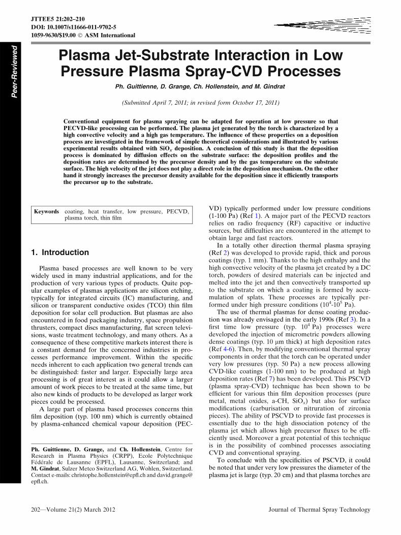
Plasma Jet-Substrate Interaction in LowPressure Plasma Spray-CVD Processes
Ph. Guittienne, D. Grange, Ch. Hollenstein, and M. Gindrat
(Submitted April 7, 2011; in revised form October 17, 2011)
Conventional equipment for plasma spraying can be adapted for operation at low pressure so thatPECVD-like processing can be performed. The plasma jet generated by the torch is characterized by ahigh convective velocity and a high gas temperature. The influence of these properties on a depositionprocess are investigated in the framework of simple theoretical considerations and illustrated by variousexperimental results obtained with SiOx deposition. A conclusion of this study is that the depositionprocess is dominated by diffusion effects on the substrate surface: the deposition profiles and thedeposition rates are determined by the precursor density and by the gas temperature on the substratesurface. The high velocity of the jet does not play a direct role in the deposition mechanism. On the otherhand it strongly increases the precursor density available for the deposition since it efficiently transportsthe precursor up to the substrate.
Keywords coating, heat transfer, low pressure, PECVD,plasma torch, thin film
1. Introduction
Plasma based processes are well known to be verywidely used in many industrial applications, and for theproduction of very various types of products. Quite pop-ular examples of plasmas applications are silicon etching,typically for integrated circuits (IC) manufacturing, andsilicon or transparent conductive oxides (TCO) thin filmdeposition for solar cell production. But plasmas are alsoencountered in food packaging industry, space propulsionthrusters, compact discs manufacturing, flat screen televi-sions, waste treatment technology, and many others. As aconsequence of these competitive markets interest there isa constant demand for the concerned industries in pro-cesses performance improvement. Within the specificneeds inherent to each application two general trends canbe distinguished: faster and larger. Especially large areaprocessing is of great interest as it could allow a largeramount of work pieces to be treated at the same time, butalso new kinds of products to be developed as larger workpieces could be processed.
A large part of plasma based processes concerns thinfilm deposition (typ. 100 nm) which is currently obtainedby plasma-enhanced chemical vapour deposition (PEC-
VD) typically performed under low pressure conditions(1-100 Pa) (Ref 1). A major part of the PECVD reactorsrelies on radio frequency (RF) capacitive or inductivesources, but difficulties are encountered in the attempt toobtain large and fast reactors.
In a totally other direction thermal plasma spraying(Ref 2) was developed to provide rapid, thick and porouscoatings (typ. 1 mm). Thanks to the high enthalpy and thehigh convective velocity of the plasma jet created by a DCtorch, powders of desired materials can be injected andmelted into the jet and then convectively transported upto the substrate on which a coating is formed by accu-mulation of splats. These processes are typically per-formed under high pressure conditions (104-105 Pa).
The use of thermal plasmas for dense coating produc-tion was already envisaged in the early 1990s (Ref 3). In afirst time low pressure (typ. 104 Pa) processes weredeveloped the injection of micrometric powders allowingdense coatings (typ. 10 lm thick) at high deposition rates(Ref 4-6). Then, by modifying conventional thermal spraycomponents in order that the torch can be operated undervery low pressures (typ. 50 Pa) a new process allowingCVD-like coatings (1-100 nm) to be produced at highdeposition rates (Ref 7) has been developed. This PSCVD(plasma spray-CVD) technique has been shown to beefficient for various thin film deposition processes (puremetal, metal oxides, a-CH, SiOx) but also for surfacemodifications (carburisation or nitruration of zirconiapieces). The ability of PSCVD to provide fast processes isessentially due to the high dissociation potency of theplasma jet which allows high precursor fluxes to be effi-ciently used. Moreover a great potential of this techniqueis in the possibility of combined processes associatingCVD and conventional spraying.
To conclude with the specificities of PSCVD, it couldbe noted that under very low pressures the diameter of theplasma jet is large (typ. 20 cm) and that plasma torches are
Ph. Guittienne, D. Grange, and Ch. Hollenstein, Centre forResearch in Plasma Physics (CRPP), Ecole PolytechniqueFederale de Lausanne (EPFL), Lausanne, Switzerland; andM. Gindrat, Sulzer Metco Switzerland AG, Wohlen, Switzerland.Contact e-mails: [email protected] and [email protected].
JTTEE5 21:202–210
DOI: 10.1007/s11666-011-9702-5
1059-9630/$19.00 � ASM International
202—Volume 21(2) March 2012 Journal of Thermal Spray Technology
Peer-
Revie
wed
currently mounted on multi-axis displacement system. Itthen appears that PSCVD could be a very interestingcandidate for some large area processing.
In comparison with conventional PECVD systems,based on sustained glow discharges, the PSCVD obviouslypresents some major differences: the plasma jet isapproximately thermalized (electrons, ions and neutralshave the same temperature), the gas temperature into thejet is very high (typ. 1000 K in the vicinity of the substrate)and finally the plasma impinges on the substrate with avery high convective axial velocity (typ. 500 m/s) (Ref 7).The question then arises as how, and in what proportions,these specificities affect the CVD processes. We can ex-pect the thermalization of the plasma to have mainly someconsequences on the process chemistry, but this aspect isbeyond the scope of this article. We focus here on theimpact of the high convective velocity and of the hightemperature of the plasma jet on the coating formation. Ina first step theoretical considerations will be introduced tofigure out what are the relevant parameters with regard tothe deposition mechanisms and how these can be affectedby the jet velocity and temperature. Then a selection ofexperimental results will be presented and analysedaccording to this theoretical approach.
2. Theoretical Approachof the Jet-Substrate Interaction
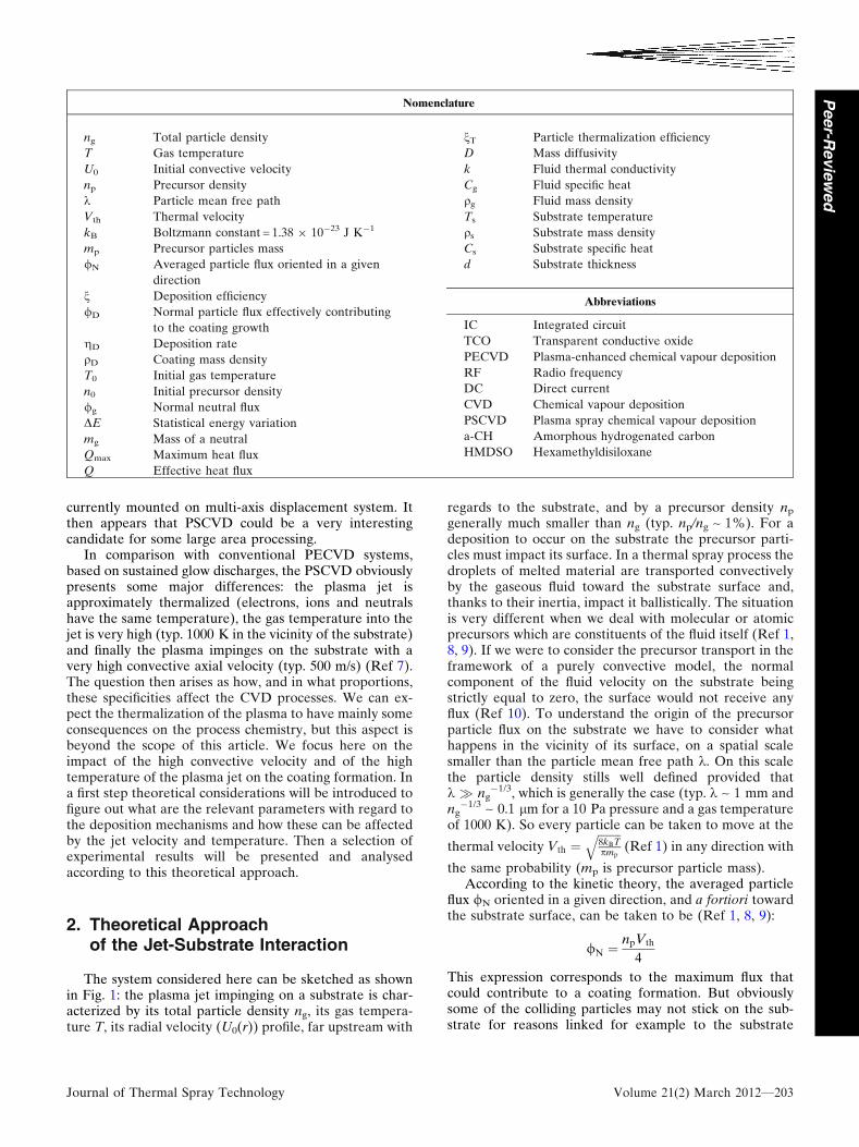
The system considered here can be sketched as shownin Fig. 1: the plasma jet impinging on a substrate is char-acterized by its total particle density ng, its gas tempera-ture T, its radial velocity (U0(r)) profile, far upstream with
regards to the substrate, and by a precursor density np
generally much smaller than ng (typ. np/ng ~ 1%). For adeposition to occur on the substrate the precursor parti-cles must impact its surface. In a thermal spray process thedroplets of melted material are transported convectivelyby the gaseous fluid toward the substrate surface and,thanks to their inertia, impact it ballistically. The situationis very different when we deal with molecular or atomicprecursors which are constituents of the fluid itself (Ref 1,8, 9). If we were to consider the precursor transport in theframework of a purely convective model, the normalcomponent of the fluid velocity on the substrate beingstrictly equal to zero, the surface would not receive anyflux (Ref 10). To understand the origin of the precursorparticle flux on the substrate we have to consider whathappens in the vicinity of its surface, on a spatial scalesmaller than the particle mean free path k. On this scalethe particle density stills well defined provided thatk � ng
�1/3, which is generally the case (typ. k ~ 1 mm andng�1/3 ~ 0.1 lm for a 10 Pa pressure and a gas temperature
of 1000 K). So every particle can be taken to move at the
thermal velocity Vth ¼ffiffiffiffiffiffiffiffi
8kBTpmp
q
(Ref 1) in any direction with
the same probability (mp is precursor particle mass).According to the kinetic theory, the averaged particle
flux /N oriented in a given direction, and a fortiori towardthe substrate surface, can be taken to be (Ref 1, 8, 9):
/N ¼npVth
4
This expression corresponds to the maximum flux thatcould contribute to a coating formation. But obviouslysome of the colliding particles may not stick on the sub-strate for reasons linked for example to the substrate
Nomenclature
ng Total particle density
T Gas temperature
U0 Initial convective velocity
np Precursor density
k Particle mean free path
Vth Thermal velocity
kB Boltzmann constant = 1.38 9 10�23 J K�1
mp Precursor particles mass
/N Averaged particle flux oriented in a given
direction
n Deposition efficiency
/D Normal particle flux effectively contributing
to the coating growth
gD Deposition rate
qD Coating mass density
T0 Initial gas temperature
n0 Initial precursor density
/g Normal neutral flux
DE Statistical energy variation
mg Mass of a neutral
Qmax Maximum heat flux
Q Effective heat flux
nT Particle thermalization efficiency
D Mass diffusivity
k Fluid thermal conductivity
Cg Fluid specific heat
qg Fluid mass density
Ts Substrate temperature
qs Substrate mass density
Cs Substrate specific heat
d Substrate thickness
Abbreviations
IC Integrated circuit
TCO Transparent conductive oxide
PECVD Plasma-enhanced chemical vapour deposition
RF Radio frequency
DC Direct current
CVD Chemical vapour deposition
PSCVD Plasma spray chemical vapour deposition
a-CH Amorphous hydrogenated carbon
HMDSO Hexamethyldisiloxane
Journal of Thermal Spray Technology Volume 21(2) March 2012—203
Peer-R
evie
wed
temperature or to the process chemistry. All these influ-ences can be taken into account by introducing a deposi-tion efficiency, or sticking coefficient, n (Ref 11) so thatthe normal flux /D effectively contributing to the coatinggrowth is finally given by:
/D ¼ n/N ¼ nnpVth
4
The deposition rate gD can be related to /D as fol-lows:gD ¼
/Dmp
qD, with qD the coating mass density.
It has to be said that the mass flux mp/D associated tothe deposition process is responsible for a convective fluxon the substrate surface known as the Stephan flow (Ref9). In the present case the Stephan velocity can be esti-mated to be 0.25 m s�1, and can then be neglected withregard to the particle thermal velocity (typ. 750 m s�1).
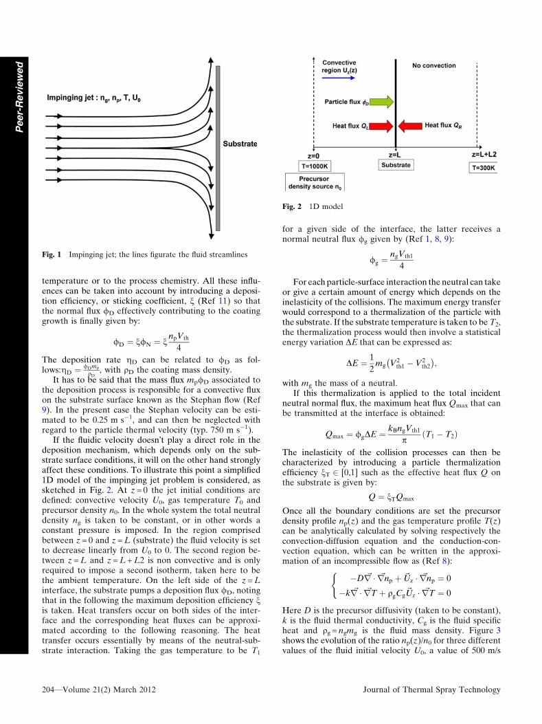
If the fluidic velocity doesn�t play a direct role in thedeposition mechanism, which depends only on the sub-strate surface conditions, it will on the other hand stronglyaffect these conditions. To illustrate this point a simplified1D model of the impinging jet problem is considered, assketched in Fig. 2. At z = 0 the jet initial conditions aredefined: convective velocity U0, gas temperature T0 andprecursor density n0. In the whole system the total neutraldensity ng is taken to be constant, or in other words aconstant pressure is imposed. In the region comprisedbetween z = 0 and z = L (substrate) the fluid velocity is setto decrease linearly from U0 to 0. The second region be-tween z = L and z = L + L2 is non convective and is onlyrequired to impose a second isotherm, taken here to bethe ambient temperature. On the left side of the z = Linterface, the substrate pumps a deposition flux /D, notingthat in the following the maximum deposition efficiency nis taken. Heat transfers occur on both sides of the inter-face and the corresponding heat fluxes can be approxi-mated according to the following reasoning. The heattransfer occurs essentially by means of the neutral-sub-strate interaction. Taking the gas temperature to be T1
for a given side of the interface, the latter receives anormal neutral flux /g given by (Ref 1, 8, 9):
/g ¼ngVth1
4
For each particle-surface interaction the neutral can takeor give a certain amount of energy which depends on theinelasticity of the collisions. The maximum energy transferwould correspond to a thermalization of the particle withthe substrate. If the substrate temperature is taken to be T2,the thermalization process would then involve a statisticalenergy variation DE that can be expressed as:
DE ¼ 1
2mg V2
th1 � V2th2
� �
;
with mg the mass of a neutral.If this thermalization is applied to the total incident
neutral normal flux, the maximum heat flux Qmax that canbe transmitted at the interface is obtained:
Qmax ¼ /gDE ¼ kBngVth1
pT1 � T2ð Þ
The inelasticity of the collision processes can then becharacterized by introducing a particle thermalizationefficiency nT 2 [0,1] such as the effective heat flux Q onthe substrate is given by:
Q ¼ nTQmax
Once all the boundary conditions are set the precursordensity profile np(z) and the gas temperature profile T(z)can be analytically calculated by solving respectively theconvection-diffusion equation and the conduction-con-vection equation, which can be written in the approxi-mation of an incompressible flow as (Ref 8):
�D ~r � ~rnp þ ~Uz � ~rnp ¼ 0
�k ~r � ~rT þ qgCg~Uz � ~rT ¼ 0
(
Here D is the precursor diffusivity (taken to be constant),k is the fluid thermal conductivity, Cg is the fluid specificheat and qg = ngmg is the fluid mass density. Figure 3shows the evolution of the ratio np(z)/n0 for three differentvalues of the fluid initial velocity U0, a value of 500 m/s
Fig. 1 Impinging jet; the lines figurate the fluid streamlines
Fig. 2 1D model
204—Volume 21(2) March 2012 Journal of Thermal Spray Technology
Peer-
Revie
wed
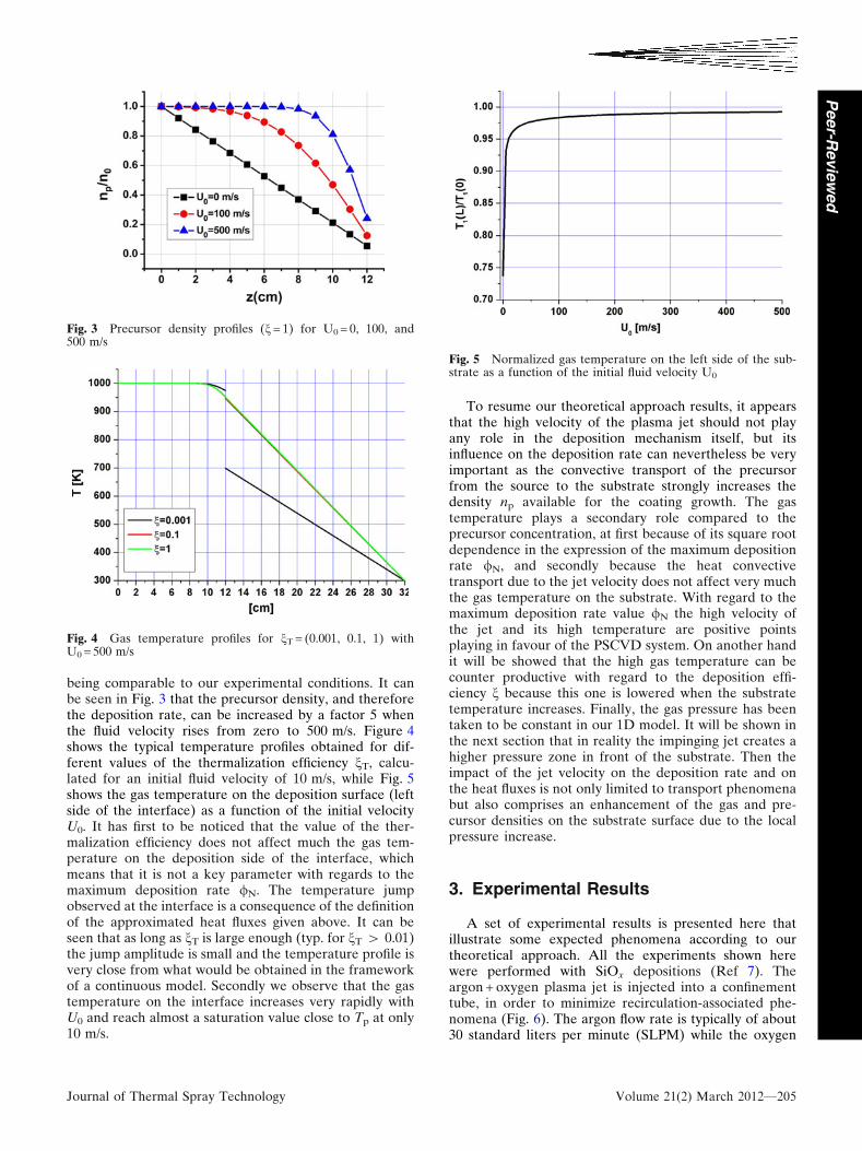
being comparable to our experimental conditions. It canbe seen in Fig. 3 that the precursor density, and thereforethe deposition rate, can be increased by a factor 5 whenthe fluid velocity rises from zero to 500 m/s. Figure 4shows the typical temperature profiles obtained for dif-ferent values of the thermalization efficiency nT, calcu-lated for an initial fluid velocity of 10 m/s, while Fig. 5shows the gas temperature on the deposition surface (leftside of the interface) as a function of the initial velocityU0. It has first to be noticed that the value of the ther-malization efficiency does not affect much the gas tem-perature on the deposition side of the interface, whichmeans that it is not a key parameter with regards to themaximum deposition rate /N. The temperature jumpobserved at the interface is a consequence of the definitionof the approximated heat fluxes given above. It can beseen that as long as nT is large enough (typ. for nT > 0.01)the jump amplitude is small and the temperature profile isvery close from what would be obtained in the frameworkof a continuous model. Secondly we observe that the gastemperature on the interface increases very rapidly withU0 and reach almost a saturation value close to Tp at only10 m/s.
To resume our theoretical approach results, it appearsthat the high velocity of the plasma jet should not playany role in the deposition mechanism itself, but itsinfluence on the deposition rate can nevertheless be veryimportant as the convective transport of the precursorfrom the source to the substrate strongly increases thedensity np available for the coating growth. The gastemperature plays a secondary role compared to theprecursor concentration, at first because of its square rootdependence in the expression of the maximum depositionrate /N, and secondly because the heat convectivetransport due to the jet velocity does not affect very muchthe gas temperature on the substrate. With regard to themaximum deposition rate value /N the high velocity ofthe jet and its high temperature are positive pointsplaying in favour of the PSCVD system. On another handit will be showed that the high gas temperature can becounter productive with regard to the deposition effi-ciency n because this one is lowered when the substratetemperature increases. Finally, the gas pressure has beentaken to be constant in our 1D model. It will be shown inthe next section that in reality the impinging jet creates ahigher pressure zone in front of the substrate. Then theimpact of the jet velocity on the deposition rate and onthe heat fluxes is not only limited to transport phenomenabut also comprises an enhancement of the gas and pre-cursor densities on the substrate surface due to the localpressure increase.
3. Experimental Results
A set of experimental results is presented here thatillustrate some expected phenomena according to ourtheoretical approach. All the experiments shown herewere performed with SiOx depositions (Ref 7). Theargon + oxygen plasma jet is injected into a confinementtube, in order to minimize recirculation-associated phe-nomena (Fig. 6). The argon flow rate is typically of about30 standard liters per minute (SLPM) while the oxygen
Fig. 3 Precursor density profiles (n = 1) for U0 = 0, 100, and500 m/s
Fig. 4 Gas temperature profiles for nT = (0.001, 0.1, 1) withU0 = 500 m/s
Fig. 5 Normalized gas temperature on the left side of the sub-strate as a function of the initial fluid velocity U0
Journal of Thermal Spray Technology Volume 21(2) March 2012—205
Peer-R
evie
wed
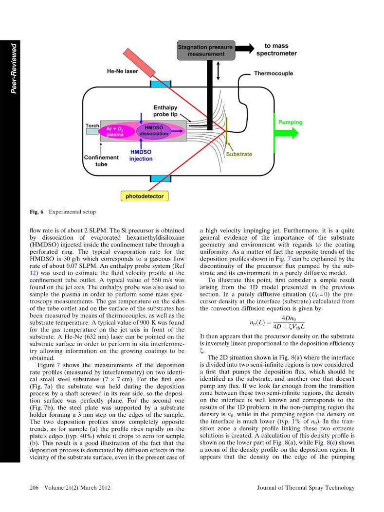
flow rate is of about 2 SLPM. The Si precursor is obtainedby dissociation of evaporated hexamethyldisiloxane(HMDSO) injected inside the confinement tube through aperforated ring. The typical evaporation rate for theHMDSO is 30 g/h which corresponds to a gaseous flowrate of about 0.07 SLPM. An enthalpy probe system (Ref12) was used to estimate the fluid velocity profile at theconfinement tube outlet. A typical value of 550 m/s wasfound on the jet axis. The enthalpy probe was also used tosample the plasma in order to perform some mass spec-troscopy measurements. The gas temperature on the sidesof the tube outlet and on the surface of the substrates hasbeen measured by means of thermocouples, as well as thesubstrate temperature. A typical value of 900 K was foundfor the gas temperature on the jet axis in front of thesubstrate. A He-Ne (632 nm) laser can be pointed on thesubstrate surface in order to perform in situ interferome-try allowing information on the growing coatings to beobtained.
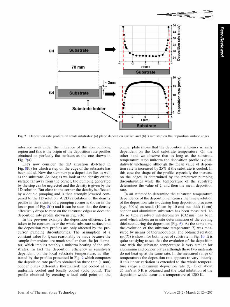
Figure 7 shows the measurements of the depositionrate profiles (measured by interferometry) on two identi-cal small steel substrates (7 9 7 cm). For the first one(Fig. 7a) the substrate was held during the depositionprocess by a shaft screwed in its rear side, so the deposi-tion surface was perfectly plane. For the second one(Fig. 7b), the steel plate was supported by a substrateholder forming a 3 mm step on the edges of the sample.The two deposition profiles show completely oppositetrends, as for sample (a) the profile rises rapidly on theplate�s edges (typ. 40%) while it drops to zero for sample(b). This result is a good illustration of the fact that thedeposition process is dominated by diffusion effects in thevicinity of the substrate surface, even in the present case of
a high velocity impinging jet. Furthermore, it is a quitegeneral evidence of the importance of the substrategeometry and environment with regards to the coatinguniformity. As a matter of fact the opposite trends of thedeposition profiles shown in Fig. 7 can be explained by thediscontinuity of the precursor flux pumped by the sub-strate and its environment in a purely diffusive model.
To illustrate this point, first consider a simple resultarising from the 1D model presented in the previoussection. In a purely diffusive situation (U0 = 0) the pre-cursor density at the interface (substrate) calculated fromthe convection-diffusion equation is given by:
np Lð Þ ¼ 4Dn0
4Dþ nVthL
It then appears that the precursor density on the substrateis inversely linear proportional to the deposition efficiencyn.
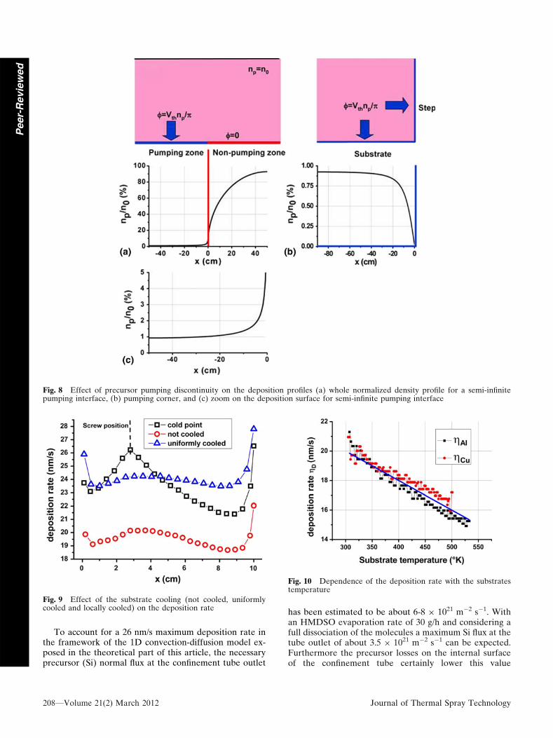
The 2D situation shown in Fig. 8(a) where the interfaceis divided into two semi-infinite regions is now considered:a first that pumps the deposition flux, which should beidentified as the substrate, and another one that doesn�tpump any flux. If we look far enough from the transitionzone between these two semi-infinite regions, the densityon the interface is well known and corresponds to theresults of the 1D problem: in the non-pumping region thedensity is n0, while in the pumping region the density onthe interface is much lower (typ. 1% of n0). In the tran-sition zone a density profile linking these two extremesolutions is created. A calculation of this density profile isshown on the lower part of Fig. 8(a), while Fig. 8(c) showsa zoom of the density profile on the deposition region. Itappears that the density on the edge of the pumping
Fig. 6 Experimental setup
206—Volume 21(2) March 2012 Journal of Thermal Spray Technology
Peer-
Revie
wed
interface rises under the influence of the non pumpingregion and this is the origin of the deposition rate profilesobtained on perfectly flat surfaces as the one shown inFig. 7(a).
Let�s now consider the 2D situation sketched inFig. 8(b) for which a step on the edge of the substrate hasbeen added. Now the step pumps a deposition flux as wellas the substrate. As long as we look at the density on thesurface far away from the corner, the pumping generatedby the step can be neglected and the density is given by the1D solution. But close to the corner the density is affectedby a double pumping and is then strongly lowered com-pared to the 1D solution. A 2D calculation of the densityprofile in the vicinity of a pumping corner is shown in thelower part of Fig. 8(b) and it can be seen that the densityeffectively drops to zero on the substrate edges as does thedeposition rate profile shown in Fig. 7(b).
In the previous example the deposition efficiency n istaken to be constant over the whole substrate surface andthe deposition rate profiles are only affected by the pre-cursor pumping discontinuities. The assumption of aconstant value for n can reasonably be made because thesample dimensions are much smaller than the jet diame-ter, which implies notably a uniform heating of the sub-strates. In fact the deposition efficiency is sensitivelydependant on the local substrate temperature, as illus-trated by the profiles presented in Fig. 9 which comparesthe deposition rate profiles obtained on three thin (1 mm)copper plates differently thermalized: not cooled at all,uniformly cooled and locally cooled (cold point). Theprofile obtained by creating a local cold point on the
copper plate shows that the deposition efficiency is reallydependent on the local substrate temperature. On theother hand we observe that as long as the substratetemperature stays uniform the deposition profile is qual-itatively unchanged although the mean value of deposi-tion rate is increased by 25% if the substrate is cooled. Inthis case the shape of the profile, especially the increaseon the edges, is determined by the precursor pumpingdiscontinuities while the temperature of the substratedetermines the value of n, and then the mean depositionrate.
In an attempt to determine the substrate temperaturedependence of the deposition efficiency the time evolutionof the deposition rate gD during long deposition processes(typ. 500 s) on small (10 cm by 10 cm) but thick (1 cm)copper and aluminium substrates has been measured. Todo so time resolved interferometry (632 nm) has beenused which allows an in situ determination of the coatingthickness during the deposition (Fig. 6). At the same timethe evolution of the substrate temperature Ts was mea-sured by means of thermocouples. The obtained relationgD(Ts) is shown for both types of substrate in Fig. 10. It isquite satisfying to see that the evolution of the depositionrate with the substrate temperature is very similar foraluminium and copper plates although these two materialsdo not heat up at the same rate. In the measured range oftemperatures the deposition rate appears to vary linearly;if this linear variation is extended to the whole tempera-ture range a maximum deposition rate (n = 1) of about26 nm/s at 0 K is obtained and the total inhibition of thedeposition would occur at a temperature of 1200 K.
Fig. 7 Deposition rate profiles on small substrates: (a) plane deposition surface and (b) 3 mm step on the deposition surface edges
Journal of Thermal Spray Technology Volume 21(2) March 2012—207
Peer-R
evie
wed
To account for a 26 nm/s maximum deposition rate inthe framework of the 1D convection-diffusion model ex-posed in the theoretical part of this article, the necessaryprecursor (Si) normal flux at the confinement tube outlet
has been estimated to be about 6-8 9 1021 m�2 s�1. Withan HMDSO evaporation rate of 30 g/h and considering afull dissociation of the molecules a maximum Si flux at thetube outlet of about 3.5 9 1021 m�2 s�1 can be expected.Furthermore the precursor losses on the internal surfaceof the confinement tube certainly lower this value
Fig. 8 Effect of precursor pumping discontinuity on the deposition profiles (a) whole normalized density profile for a semi-infinitepumping interface, (b) pumping corner, and (c) zoom on the deposition surface for semi-infinite pumping interface
Fig. 9 Effect of the substrate cooling (not cooled, uniformlycooled and locally cooled) on the deposition rate
Fig. 10 Dependence of the deposition rate with the substratestemperature
208—Volume 21(2) March 2012 Journal of Thermal Spray Technology
Peer-
Revie
wed
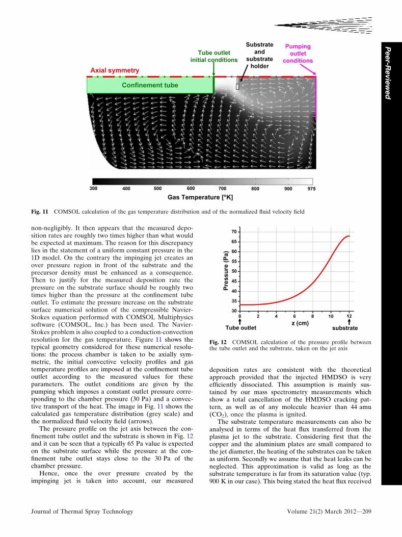
non-negligibly. It then appears that the measured depo-sition rates are roughly two times higher than what wouldbe expected at maximum. The reason for this discrepancylies in the statement of a uniform constant pressure in the1D model. On the contrary the impinging jet creates anover pressure region in front of the substrate and theprecursor density must be enhanced as a consequence.Then to justify for the measured deposition rate thepressure on the substrate surface should be roughly twotimes higher than the pressure at the confinement tubeoutlet. To estimate the pressure increase on the substratesurface numerical solution of the compressible Navier-Stokes equation performed with COMSOL Multiphysicssoftware (COMSOL, Inc.) has been used. The Navier-Stokes problem is also coupled to a conduction-convectionresolution for the gas temperature. Figure 11 shows thetypical geometry considered for these numerical resolu-tions: the process chamber is taken to be axially sym-metric, the initial convective velocity profiles and gastemperature profiles are imposed at the confinement tubeoutlet according to the measured values for theseparameters. The outlet conditions are given by thepumping which imposes a constant outlet pressure corre-sponding to the chamber pressure (30 Pa) and a convec-tive transport of the heat. The image in Fig. 11 shows thecalculated gas temperature distribution (grey scale) andthe normalized fluid velocity field (arrows).
The pressure profile on the jet axis between the con-finement tube outlet and the substrate is shown in Fig. 12and it can be seen that a typically 65 Pa value is expectedon the substrate surface while the pressure at the con-finement tube outlet stays close to the 30 Pa of thechamber pressure.
Hence, once the over pressure created by theimpinging jet is taken into account, our measured
deposition rates are consistent with the theoreticalapproach provided that the injected HMDSO is veryefficiently dissociated. This assumption is mainly sus-tained by our mass spectrometry measurements whichshow a total cancellation of the HMDSO cracking pat-tern, as well as of any molecule heavier than 44 amu(CO2), once the plasma is ignited.
The substrate temperature measurements can also beanalysed in terms of the heat flux transferred from theplasma jet to the substrate. Considering first that thecopper and the aluminium plates are small compared tothe jet diameter, the heating of the substrates can be takenas uniform. Secondly we assume that the heat leaks can beneglected. This approximation is valid as long as thesubstrate temperature is far from its saturation value (typ.900 K in our case). This being stated the heat flux received
Fig. 11 COMSOL calculation of the gas temperature distribution and of the normalized fluid velocity field
Fig. 12 COMSOL calculation of the pressure profile betweenthe tube outlet and the substrate, taken on the jet axis
Journal of Thermal Spray Technology Volume 21(2) March 2012—209
Peer-R
evie
wed
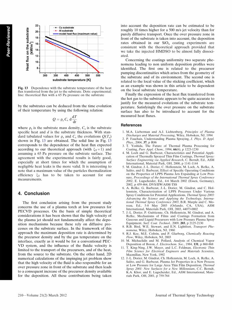
by the substrates can be deduced from the time evolutionof their temperature by using the following relation:
Q ¼ qs Cs ddT
dt
where qs is the substrate mass density, Cs is the substratespecific heat and d is the substrate thickness. With stan-dard tabulated values for qs and Cs the evolutions Q(Ts)shown in Fig. 13 are obtained. The solid line in Fig. 13corresponds to the dependence of the heat flux expectedaccording to our theoretical approach (with nT = 1) andassuming a 65 Pa pressure on the substrate surface. Theagreement with the experimental results is fairly good,especially at short times for which the assumption ofnegligible heat leaks is the more valid. It is interesting tonote that a maximum value of the particles thermalizationefficiency nT has to be taken to account for ourmeasurements.
4. Conclusion
The first conclusion arising from the present studyconcerns the use of a plasma torch at low pressures forPECVD processes. On the basis of simple theoreticalconsiderations it has been shown that the high velocity ofthe plasma jet should not fundamentally affect the depo-sition mechanisms because these rely on diffusive pro-cesses on the substrate surface. In the framework of thisapproach the maximum deposition rate is determined bythe precursor density and by the gas temperature on theinterface, exactly as it would be for a conventional PEC-VD system, and the influence of the fluidic velocity islimited to the transport of the precursors, and of the heat,from the source to the substrate. On the other hand, 2Dnumerical calculations of the impinging jet problem showthat the high velocity of the fluid is also responsible for anover pressure zone in front of the substrate and then leadsto a consequent increase of the precursor density availablefor the deposition. All these contributions being taken
into account the deposition rate can be estimated to beroughly 10 times higher for a 500 m/s jet velocity than forpurely diffusive transport. Once the over pressure zone infront of the substrate is taken into account, the depositionrates obtained in our SiOx coating experiments areconsistent with the theoretical approach provided thatwe take the injected HMDSO to be almost fully dissoci-ated.
Concerning the coatings uniformity two separate phe-nomena leading to non uniform deposition profiles wereidentified. The first one is related to the precursorpumping discontinuities which arises from the geometry ofthe substrate and of its environment. The second one isrelated to the local value of the sticking coefficient, whichas an example was shown in this article to be dependenton the local substrate temperature.
Finally the expression of the heat flux transferred fromthe hot gas to the substrate appears to be quite accurate tojustify for the measured evolutions of the substrate tem-perature. Satisfyingly the over pressure on the substratesurface has also to be introduced to account for themeasured heat fluxes.
References
1. M.A. Lieberman and A.J. Lichtenberg, Principles of PlasmaDischarges and Material Processing, Wiley, Hoboken, NJ, 1994
2. P. Fauchais, Understanding Plasma Spraying, J. Phys. D Appl.Phys., 2004, 37, p R86
3. T. Yoshida, The Future of Thermal Plasma Processing forCoating, Pure Appl. Chem., 1994, 66(6), p 1223-1230
4. M. Loch and G. Barbezat, Characteristics and Potential Appli-cation of Thermally Sprayed Thin Film Coatings, Thermal Spray:Surface Engineering via Applied Research, C. Berndt, Ed., ASMInternational, Material Park, OH, 2000, p 1141-1144
5. M. Gindrat, J.-L. Dorier, C. Hollenstein, M. Loch, A. Refke, A.Salito, and G. Barbezat, Effect of Specific Operating Conditionson the Properties of LPPS Plasma Jets Expanding at Low Pres-sure, Proceedings of the International Thermal Spray Conference2002, E. Lugscheider, Ed., 4-6 March 2002 (Essen, Germany),2002, p 459-464, DVS/IIW/ASM-TSS
6. A. Refke, G. Barbezat, J.-L. Dorier, M. Gindrat, and C. Hol-lenstein, Characterization of LPPS Processes Under VariousSpray Conditions for Potential Applications, Thermal Spray 2003:Advancing the Science and Applying the Technology, Interna-tional Thermal Spray Conference 2003, B.R. Marple and C. Mo-reau, Ed., 5-8 May 2003 (Orlando, CA, USA), ASMInternational, Materials Park, OH, 2003, 44073-0002
7. J.-L. Dorier, P. Guittienne, Ch. Hollenstein, M. Gindrat, and A.Refke, Mechanisms of Films and Coatings Formation fromGaseous and Liquid Precursors with Low Pressure Plasma SprayEquipment, Surf. Coat. Technol., 2009, 203, p 2125-2130
8. R.B. Bird, W.E. Stewart, and E.N. Lightfoot, Transport Phe-nomena, Wiley, Hoboken, NJ, 1960
9. R.J. Kee, M.E. Coltrin, and P. Glarborg, Chemically ReactingFlow, Wiley, Hoboken, NJ, 2003
10. M. Michaelidis and M. Pollard, Analysis of Chemical VaporDeposition of Boron, J. Electrochem. Soc., 1984, 131, p 860-868
11. T. King-Ning, J.W. Mayer, and L.C. Feldman, Electronic ThinFilm Science for Electrical Engineers and Materials Scientists,Macmillan, New York, 1992
12. J.-L. Dorier, M. Gindrat, Ch. Hollenstein, M. Loch, A. Refke, A.Salito, and G. Barbezat, Plasma Jet Properties in a New Processat Low Pressure for Large Area Thin Film Deposition, ThermalSpray 2001: New Surfaces for a New Millennium, C.C. Berndt,K.A. Khor, and E. Lugscheider, Ed., ASM International, Mate-rials Park, OH, 2001, p 759-764
Fig. 13 Dependence with the substrate temperature of the heatflux transferred from the jet to the substrate. Dots: experimental;line: theoretical flux with a 65 Pa pressure on the substrate
210—Volume 21(2) March 2012 Journal of Thermal Spray Technology
Peer-
Revie
wed