Embed Size (px)
Citation preview
Plasma aerodynamicexperiments
A.F.Aleksandrov, V.L.Bychkov, I.B. Timofeev
M.V.Lomonosov Moscow State University, Physical Faculty
Report Documentation Page Form ApprovedOMB No. 0704-0188
Public reporting burden for the collection of information is estimated to average 1 hour per response, including the time for reviewing instructions, searching existing data sources, gathering andmaintaining the data needed, and completing and reviewing the collection of information. Send comments regarding this burden estimate or any other aspect of this collection of information,including suggestions for reducing this burden, to Washington Headquarters Services, Directorate for Information Operations and Reports, 1215 Jefferson Davis Highway, Suite 1204, ArlingtonVA 22202-4302. Respondents should be aware that notwithstanding any other provision of law, no person shall be subject to a penalty for failing to comply with a collection of information if itdoes not display a currently valid OMB control number.
1. REPORT DATE 22 JUN 2004
2. REPORT TYPE N/A
3. DATES COVERED -
4. TITLE AND SUBTITLE Plasma aerodynamic experiments
5a. CONTRACT NUMBER
5b. GRANT NUMBER
5c. PROGRAM ELEMENT NUMBER
6. AUTHOR(S) 5d. PROJECT NUMBER
5e. TASK NUMBER
5f. WORK UNIT NUMBER
7. PERFORMING ORGANIZATION NAME(S) AND ADDRESS(ES) Moscow State University
8. PERFORMING ORGANIZATIONREPORT NUMBER
9. SPONSORING/MONITORING AGENCY NAME(S) AND ADDRESS(ES) 10. SPONSOR/MONITOR’S ACRONYM(S)
11. SPONSOR/MONITOR’S REPORT NUMBER(S)
12. DISTRIBUTION/AVAILABILITY STATEMENT Approved for public release, distribution unlimited
13. SUPPLEMENTARY NOTES See also ADM001793, International Symposium on Energy Conversion Fundamentals Held in Istanbul,Turkey on 21-25 June 2005., The original document contains color images.
14. ABSTRACT
15. SUBJECT TERMS
16. SECURITY CLASSIFICATION OF: 17. LIMITATION OF ABSTRACT
UU
18. NUMBEROF PAGES
24
19a. NAME OFRESPONSIBLE PERSON
a. REPORT unclassified
b. ABSTRACT unclassified
c. THIS PAGE unclassified
Standard Form 298 (Rev. 8-98) Prescribed by ANSI Std Z39-18
Plasma aerodynamic experiments
A.F.Aleksandrov, V.L.Bychkov, I.B. Timofeev
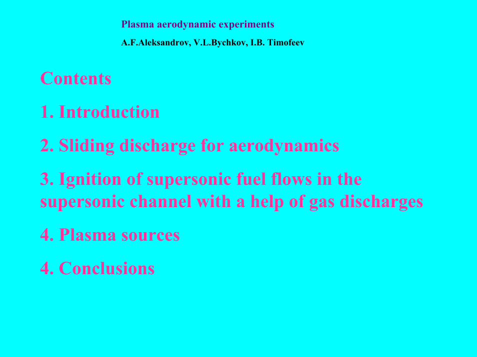
Contents
1. Introduction
2. Sliding discharge for aerodynamics
3. Ignition of supersonic fuel flows in the supersonic channel with a help of gas discharges
4. Plasma sources
4. Conclusions

1. Introduction
As it is well known plasma technologies nowadays find wide applications in aerodynamics, and it has become evident that development of hypersonic aviation is unlikely possible without application of plasma- and beam technologies.
In external aerodynamics they can be applied for drag and wave reduction and improvement of aircraft maneuraty.
Plasma technologies in internal aerodynamics can be applied for improvement of combustion processes due to usage of created volumetric plasma structures in the stagnation zone and directly in subsonic and supersonic air-fuel mixtures. Electrical gas discharges are promising methods of combustion improvement because of their ability to produce concentrated zones with high content of chemical active species.
Actually this puts the problem of understanding the nontrivial interaction of hydrodynamic, chemical and plasma-chemical phenomena.
So there is absolute necessity for detailed physical study, both experimental and theoretical, of discharge activated reacting flows at well-defined conditions.
0 2 4 6 8 10
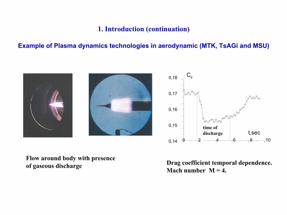
1. Introduction (continuation)
Example of Plasma dynamics technologies in aerodynamic (MTK, TsAGi and MSU)
Flow around body with presence of gaseous discharge
t.с
Сx0,18
0,17
0,16
0,15
0,14
Время горения разряда t,sec
time of discharge
Drag coefficient temporal dependence. Mach number M = 4.

1. Introduction (continuation)Tasks :
External aerodynamicsInvestigation of plasma dynamic structures interaction with high-speed flows:• Sources of plasma – pulsed or stationary• Plasma penetration into the flow• Mass-weight and energy limitations • Plasma lifetime in supersonic flow• Plasma influencing on the flow structure
Internal aerodynamics • Shortening of induction and mixing time • Sources of plasma – pulsed or stationary• Plasma influencing on the air-fuel flow structure• Mass-weight and energy limitations • Plasma lifetime in supersonic flow
Development of diagnostics methods
1. Introduction (continuation)
External aerodynamics (prospective directions of investigations):
• sliding discharge for angle of attack change;• thermal spike for wave drag reduction of vehicle. • external burning for the lift change using plasmadynamics igniters.
Internal aerodynamics:
• certification of gas discharges for applications in scramjets:–Plasma jets (stationary and pulsed)–Longitudinal and transversal gas discharges–High frequency and Microwave discharges (streamer, brush and surface discharges)
–Sliding discharges
Scientific partnership
• MSU, TsAGI, CIAM, SDO “HORIZONT” in structure of “SALUTE”, MRTI

2. Sliding discharge for aerodynamics (continuation)
thyratron500/16
Cн 15кV
RзC о J1
J2
U
R1
R2
Electric scheme of Sliding discharge,
J1, J2- Rogovsky coil,
R1, R2 –Voltage divider
Unfinished sliding discharge Ampere-Volt characteristicsin air, p=1 atm.
U- a voltage on the discharge gap, J1- a current on the discharge gap J2-a current on the charging resistance
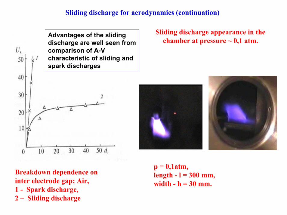
Sliding discharge for aerodynamics (continuation)
Sliding discharge appearance in the chamber at pressure ~ 0,1 atm.
Breakdown dependence on inter electrode gap: Air, 1 - Spark discharge, 2 – Sliding discharge
Advantages of the sliding discharge are well seen from comparison of A-V characteristic of sliding and spark discharges
p = 0,1atm, length - l = 300 mm,width - h = 30 mm.
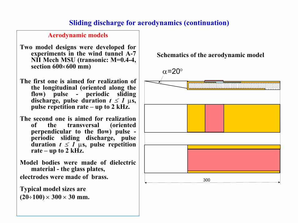
Sliding discharge for aerodynamics (continuation)Aerodynamic models
Two model designs were developed for experiments in the wind tunnel А-7 NII Mech MSU (transonic: M=0.4-4, section 600×600 mm)
The first one is aimed for realization of the longitudinal (oriented along the flow) pulse - periodic sliding discharge, pulse duration t ≤ 1 µs, pulse repetition rate – up to 2 kHz.
The second one is aimed for realization of the transversal (oriented perpendicular to the flow) pulse -periodic sliding discharge, pulse duration t ≤ 1 µs, pulse repetition rate – up to 2 kHz.
Model bodies were made of dielectric material - the glass plates,
electrodes were made of brass.
Typical model sizes are (20÷100) × 300 × 30 mm.
Schematics of the aerodynamic model
300
α=20°
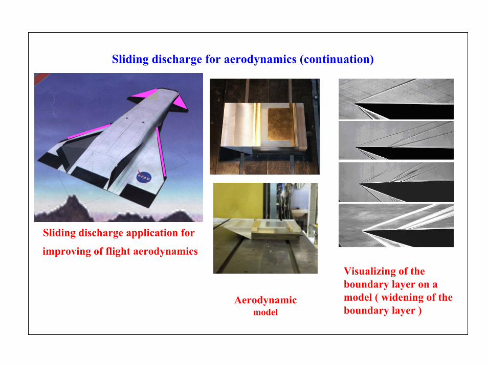
Sliding discharge for aerodynamics (continuation)
Sliding discharge application for
improving of flight aerodynamics
Visualizing of the boundary layer on a model ( widening of the boundary layer )
Aerodynamicmodel

Sliding discharge for aerodynamic (continuation)
The sliding discharge influence on the gas flow was simulated by the non-steady near wall heat source with the specified space and time distributions intensity.
• Parametric calculations of the flow over flat plate for wind tunnel experiments conditions M∞= 0.8 (total pressure p0 = 1.2 atm, and total temperature T = 300 K); and M∞= 3 (total pressure p0 = 3.7 atm, and total temperature T = 300 K) were made. The effects of heat deposition on skin-friction and near wall flow structure were studied.
• The pulse-periodic heat deposition sliding discharge modeling has been made. At that the pulse length tp was 1µs, the form of pulses was triangular, pulse frequency fpwas 10 kHz, total heat supply during one pulse (cycle) was Qp= 10-2 J/cm2.
• The simulation is based on the Favre averaged Navier-Stokes equations for thermally equilibrium chemical frozen air gas phase. Two-parametric differential k-omega turbulence model is used for the turbulence transfer description.
• Heat supply was distributed uniformly into the space region: 5 ≤ x ≤ 10 cm, 0 ≤ y ≤0.1 cm, where x, y are Cartesian coordinates attached to plate surface. This case heating distribution corresponds to the longitudinal sliding discharge.
• The skin-friction coefficient Cf for the plate section The value of Cf is defined by the expression
where τw is the local skin-friction, ρ∞ and V∞ are the free stream density and velocity respectively, xb = 0 cm, xl = 30 cm.
)(5.0/ 2be
x
xwf xxVdxC
e
b
−= ∞∞∫ ρτ
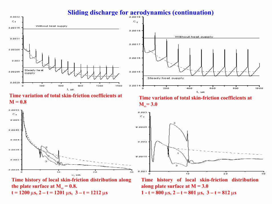
Sliding discharge for aerodynamics (continuation)
Time variation of total skin-friction coefficients at M = 0.8
Time variation of total skin-friction coefficients at M∞= 3.0
Time history of local skin-friction distribution along the plate surface at M∞ = 0.8. t = 1200 µs, 2 – t = 1201 µs, 3 – t = 1212 µs
Time history of local skin-friction distribution along plate surface at M = 3.0 1 - t = 800 µs, 2 – t = 801 µs, 3 – t = 812 µs
Ignition of supersonic fuel flows in the supersonic channel with a help of gas discharges
We have made design works and manufacturing of the supersonic channel (scramjet model).
We suppose to put different plasma generators into the channel and to study their influence on the combustion initiation and combustion stabilization in the channel.
The channel sizes and materials for its manufacturing were determined on a basis of the following requirements to the channel :
1. for modeling of conditions corresponding to the Mach number М=2 at the inlet to the channel with Рstat=0.25-0.6 atm., total parameters of airflow:
Ptot = 2-10 atm. and T =300 - 900 K;Time of stationary combustor work is no less than 5 s;
2. supersonic nozzle for М=2 and the isolating channel element for the discharge were manufactured in flat and axisymmetric variants;
3. optical quartz windows are foreseen in the region of the fuel mixture ignition for visualizing of the flow and the application of optical diagnostics;

Ignition of supersonic fuel flows in the supersonic channel with a help of gas discharges (continuation)
Supersonic channel design
1 52 1063,4 7,8 9
Quartz windows200 200
25 40
1153(44) 250
Channel scheme for combustion investigations 1,2 – supersonic nozzle М=2; 3,4 – collectors for preliminary fuel supply; 5-6 –flow stabilizing channel; 7, 8 – collectors of main fuel supply; 9 – 1-st part of the combustor, 10 – 2-nd part of the combustor (sections «9» and «10» are manufactured in 2 copies and the total channel length can be changed from 730 to 1130 mm)(linear sizes of channel sections of axisymmetric and flat configurations are equal with exception of the nozzle section «1», in frames the size of the axisymmetric channel scheme is indicated)
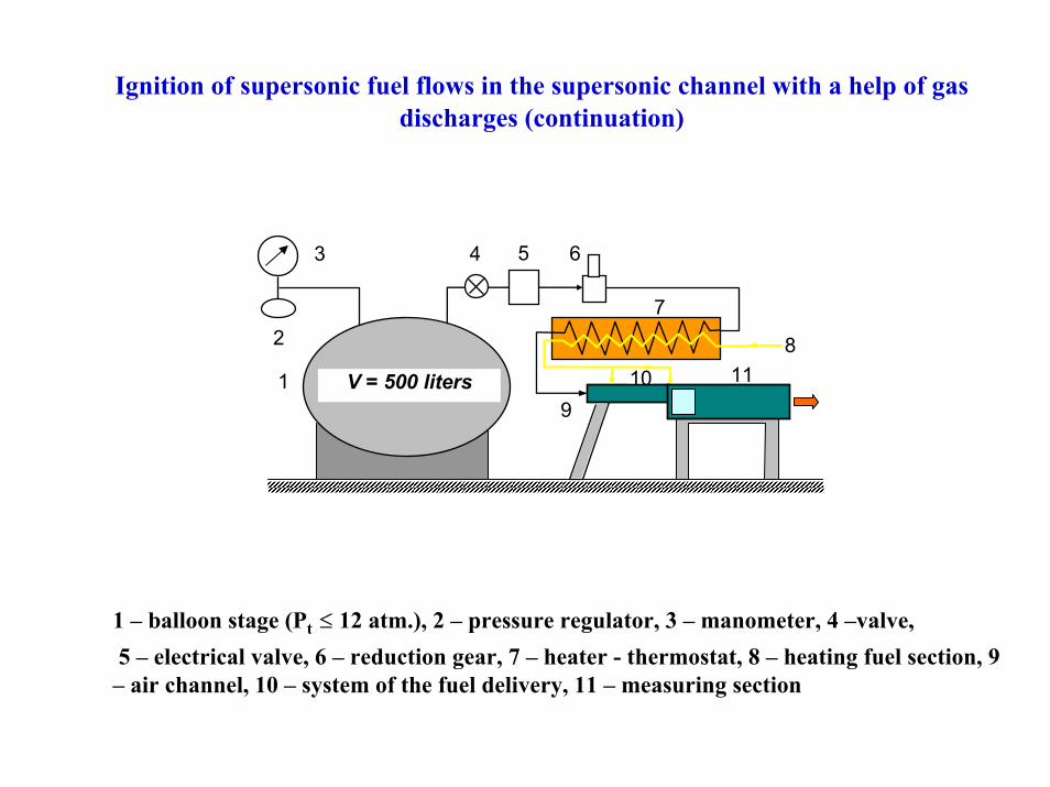
Ignition of supersonic fuel flows in the supersonic channel with a help of gas discharges (continuation)
V = 500 liters
2
9
7
810 11
5 63 4
1
1 – balloon stage (Pt ≤ 12 atm.), 2 – pressure regulator, 3 – manometer, 4 –valve,5 – electrical valve, 6 – reduction gear, 7 – heater - thermostat, 8 – heating fuel section, 9
– air channel, 10 – system of the fuel delivery, 11 – measuring section
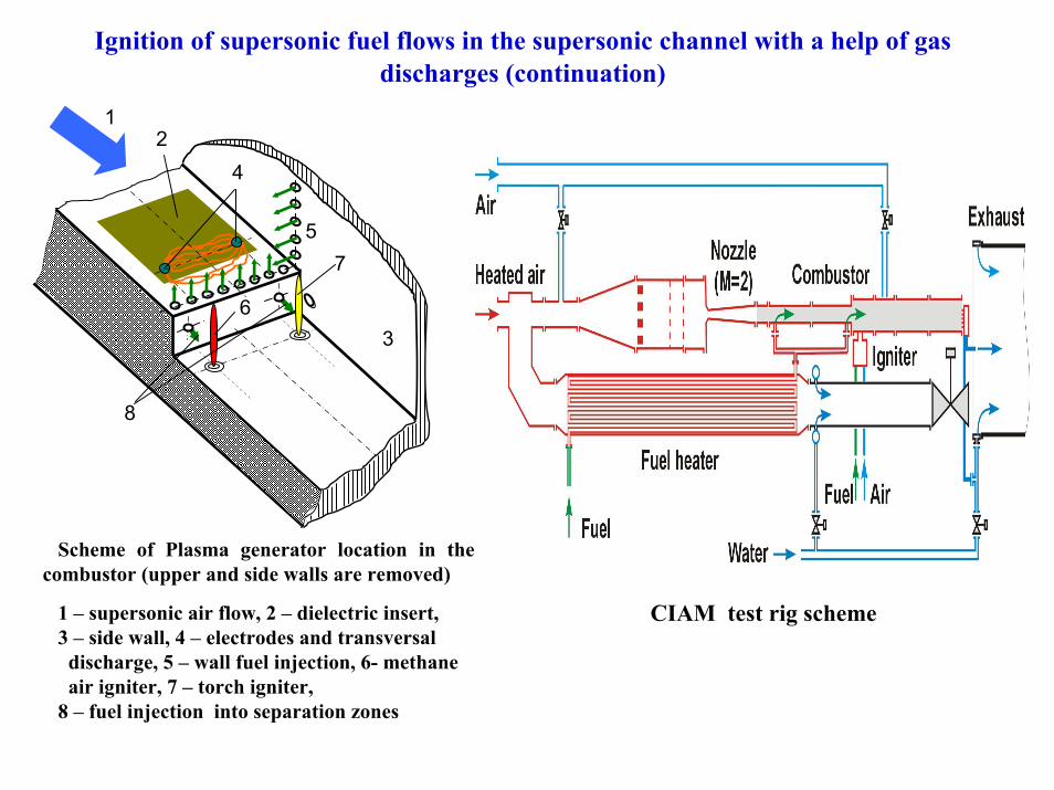
Ignition of supersonic fuel flows in the supersonic channel with a help of gas discharges (continuation)
Scheme of Plasma generator location in the combustor (upper and side walls are removed)
1 – supersonic air flow, 2 – dielectric insert, 3 – side wall, 4 – electrodes and transversal
discharge, 5 – wall fuel injection, 6- methaneair igniter, 7 – torch igniter,
8 – fuel injection into separation zones
12
3
4
57
6
8
CIAM test rig scheme
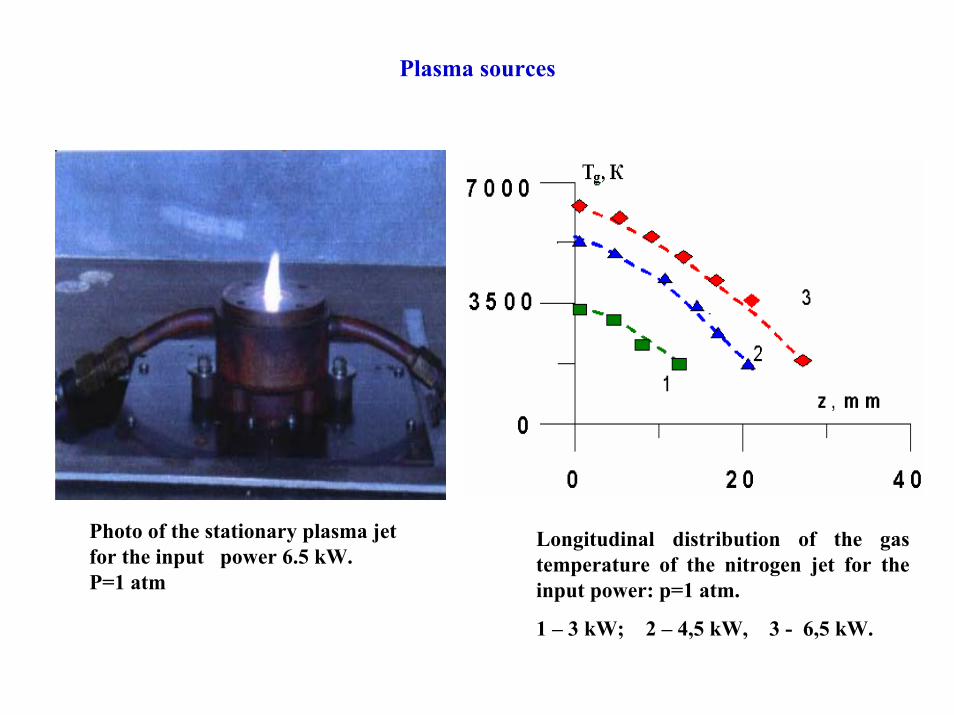
Plasma sources
Photo of the stationary plasma jet for the input power 6.5 kW. P=1 atm
Longitudinal distribution of the gas temperature of the nitrogen jet for the input power: p=1 atm.
1 – 3 kW; 2 – 4,5 kW, 3 - 6,5 kW.
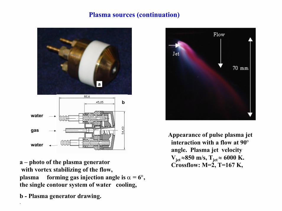
Plasma sources (continuation)
a – photo of the plasma generator with vortex stabilizing of the flow, plasma forming gas injection angle is α = 6°, the single contour system of water cooling,
b - Plasma generator drawing. .
a
water
water
gas
b
Appearance of pulse plasma jetinteraction with a flow at 90°angle. Plasma jet velocityVjet ≈850 m/s, Tjet ≈ 6000 K. Crossflow: M=2, T=167 K,
Plasma sources (continuation)
a b1
2
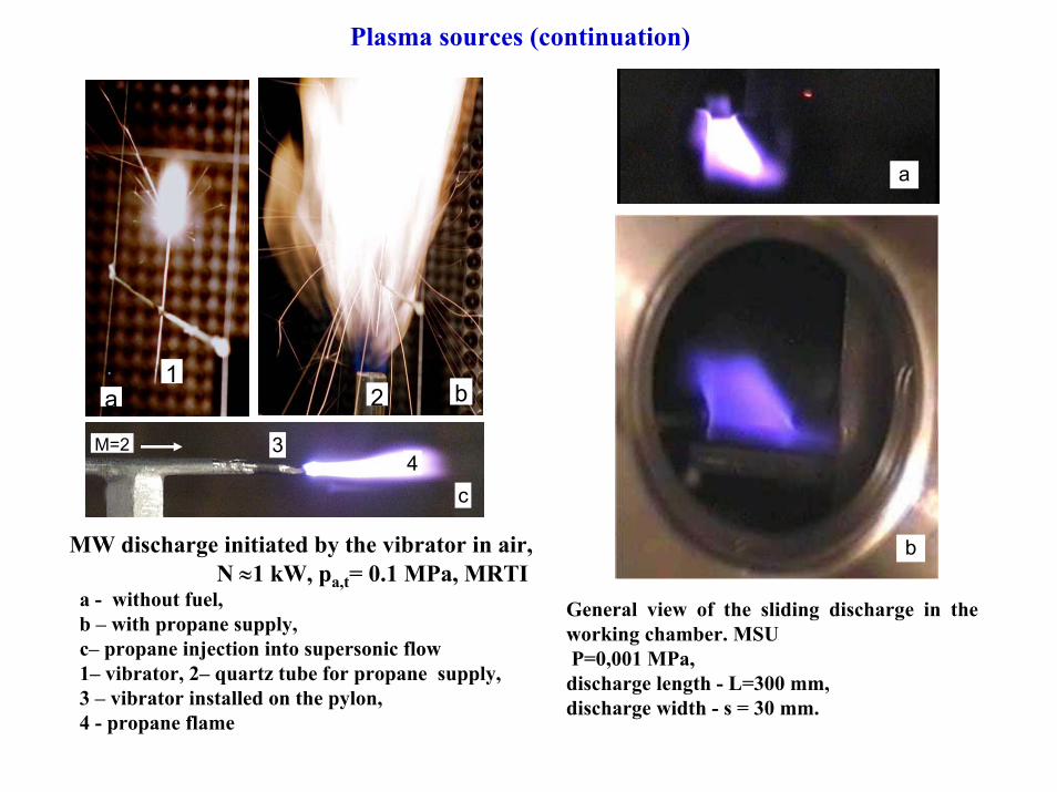
MW discharge initiated by the vibrator in air, N ≈1 kW, pa,t= 0.1 MPa, MRTI
a - without fuel,b – with propane supply,c– propane injection into supersonic flow1– vibrator, 2– quartz tube for propane supply,3 – vibrator installed on the pylon,4 - propane flame
M=2 34
с
General view of the sliding discharge in the working chamber. MSUP=0,001 MPa,discharge length - L=300 mm, discharge width - s = 30 mm.
a
b
Plasma sources (continuation)
a b
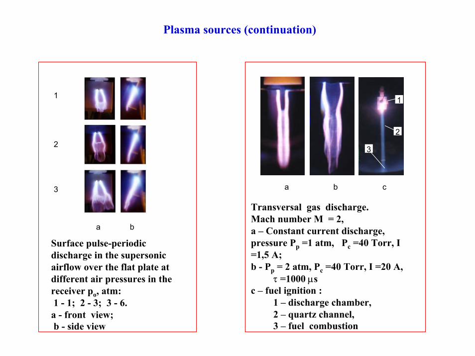
Surface pulse-periodic discharge in the supersonic airflow over the flat plate at different air pressures in the receiver ро, atm:1 - 1; 2 - 3; 3 - 6. а - front view;b - side view
1
2
3
Transversal gas discharge. Mach number М = 2, a – Constant current discharge, pressure Pр =1 atm, Pс =40 Torr, I =1,5 A; b - Pр = 2 atm, Pс =40 Torr, I =20 A,
τ =1000 µsс – fuel ignition :
1 – discharge chamber, 2 – quartz channel,3 – fuel combustion
a b c
1
2
3
Plasma sources (continuation)
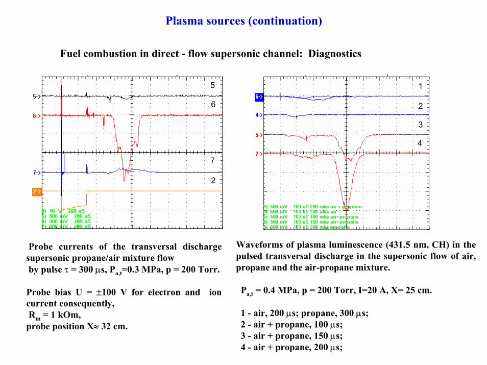
Fuel combustion in direct - flow supersonic channel: Diagnostics
3
2
1
4
2
5
6
7
Waveforms of plasma luminescence (431.5 nm, CH) in the pulsed transversal discharge in the supersonic flow of air, propane and the air-propane mixture.
Pa,t = 0.4 MPa, p = 200 Torr, I=20 A, X= 25 cm.
1 - air, 200 µs; propane, 300 µs;2 - air + propane, 100 µs;3 - air + propane, 150 µs;4 - air + propane, 200 µs;
Probe currents of the transversal discharge supersonic propane/air mixture flowby pulse τ = 300 µs, Pa,t=0.3 MPa, p = 200 Torr.
Probe bias U = ±100 V for electron and ion current consequently,Rm = 1 kOm, probe position X≈ 32 cm.
Plasma sources (continuation)
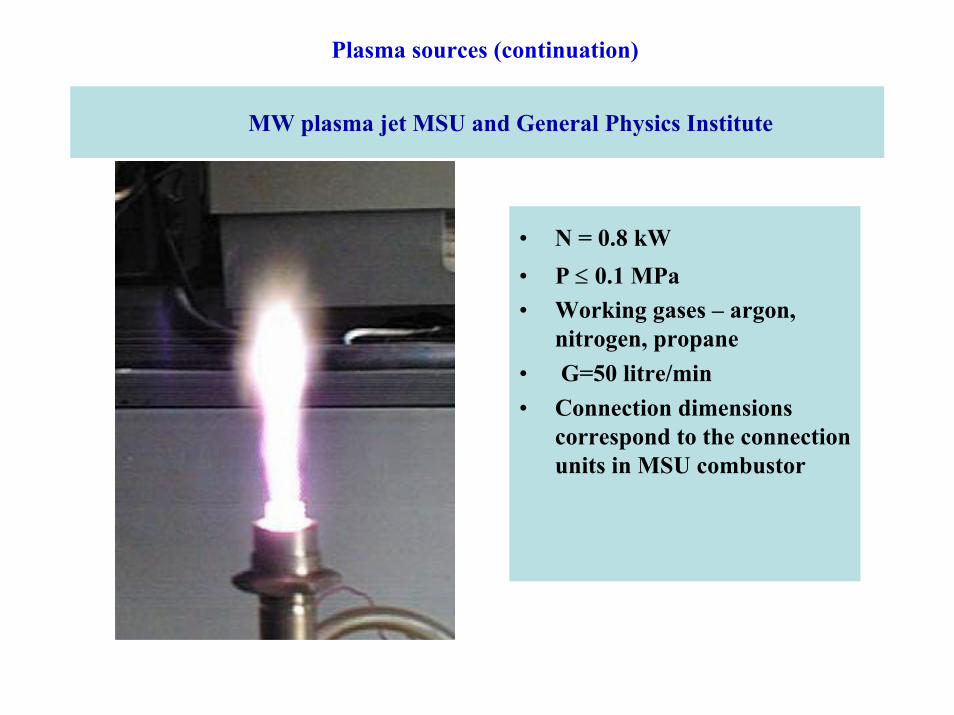
MW plasma jet MSU and General Physics Institute
• N = 0.8 kW• P ≤ 0.1 MPa• Working gases – argon,
nitrogen, propane• G=50 litre/min• Connection dimensions
correspond to the connection units in MSU combustor
Conclusions
During last two years the following works were realized in frames of works with EOARD :
1. Theoretical and experimental investigations of plasma jet interaction with air and propane-air flows, Project ISTC # 2449-p;
2. Theoretical and experimental investigations of sliding discharge has been made, Project CRDF # RPO-1382
3. Aerodynamic models of sliding discharge for experiments in wind tunnel A-7 has been made. Sliding discharge parameters in air have been investigated, pilot blow-thtroughs in wind tunnel A-7 have been made for visualizing of the boundary layer, Project CRDF # RPO-1382
4. The supersonic combustor has been developed, manufactured and completed by the diagnostic equipment, Project CRDF # RCO-1383
Prospects
1. Development of theoretical models of plasma-jet cross flow air-fuel mix interaction for optimization of combustion modes.
2. Experimental investigations of plasma-jet cross flow air-fuel mix interactions.
3. Investigation of the sliding discharge influence on the boundary layer structure and surface friction.
4. Optimization of sliding discharge sources work with respect to energy losses.
5. Analysis of sliding discharge applicability for fuel ignition in the supersonic channel (preliminary results has been obtained).
6. Development of works on ignition and combustion stabilization ofhydrocarbon fuels in the supersonic combustor.
7. Scaling works on plasma aerodynamic experiments
Acknowledgments
Authors Acknowledge EOARD for Financial support of investigations in frames of Projects ISTC # 2449-p; CRDF # RPO-1382; RCO-1383