Embed Size (px)
Citation preview
Plants of lube oil section
No Name of the plant Designation in this
presentation as
1 Distillation Plant (plant 1) PL-1
2 Deasphalting unit, DOA (plant 71) PL-2
3 Furfural Extracting Unit , FEU (plant 8) PL-3
4 N-methyl-2 Pyrrolidone Extraction unit,
NMP (plant 73) PL-4
5 Methyl Ethyl ketone Dewaxing Plant,
MEK (plant 9)PL-5
6 Hydro Finishing Unit, HFU (Plant 10) PL-6
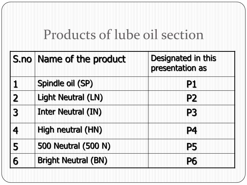
Products of lube oil section
S.no Name of the product Designated in this presentation as
1 Spindle oil (SP) P1
2 Light Neutral (LN) P2
3 Inter Neutral (IN) P3
4 High neutral (HN) P4
5 500 Neutral (500 N) P5
6 Bright Neutral (BN) P6
P
L
1
PL71
P
L
8
P
L
9
P
L
73
PL
10
Plant 4
Plant 2
Plant 1
Plant 3
Plant 5
Plant 6
Slop Tank
SP
LN
IN
HN
500 N
BN
LN
SP
IN
HN
500 N
BN
SP
LN
IN
HN
500 N
BN
VR
SP
LN
IN
HN
500 N
BN
Crude
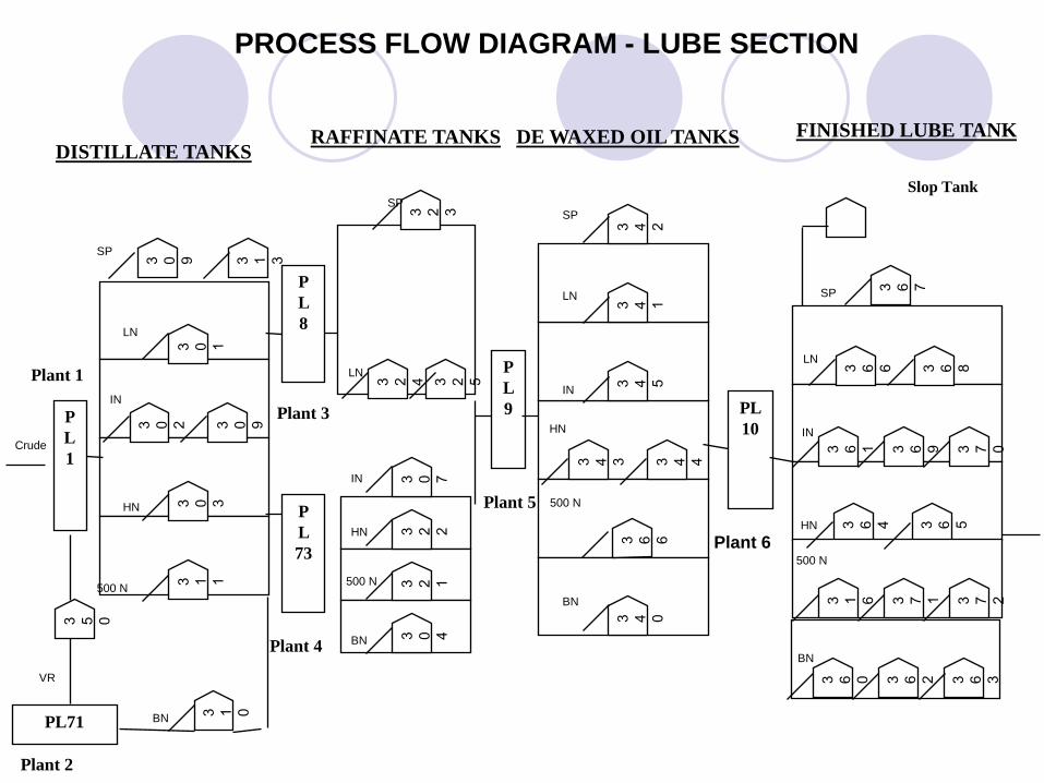
DISTILLATE TANKSRAFFINATE TANKS DE WAXED OIL TANKS FINISHED LUBE TANK
PROCESS FLOW DIAGRAM - LUBE SECTION
Four stages in lube oil section The stages are,
-Distillation
-Raffination
-Dewaxing
-Hydro finishing
Distillation This stage consists of PL 1 with six oil tanks.
Input to this stage is crude oil.
Crude oil undergoes a distillate separation process in PL 1.
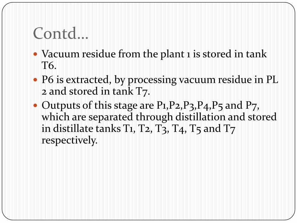
Contd… Vacuum residue from the plant 1 is stored in tank
T6.
P6 is extracted, by processing vacuum residue in PL 2 and stored in tank T7.
Outputs of this stage are P1,P2,P3,P4,P5 and P7, which are separated through distillation and stored in distillate tanks T1, T2, T3, T4, T5 and T7 respectively.
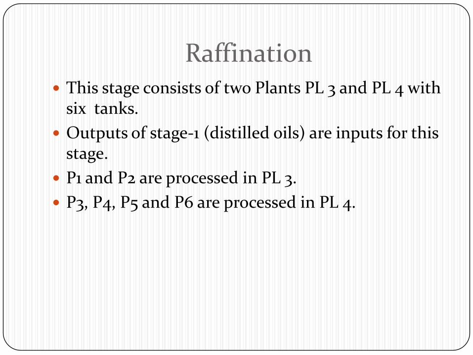
Raffination This stage consists of two Plants PL 3 and PL 4 with
six tanks.
Outputs of stage-1 (distilled oils) are inputs for this stage.
P1 and P2 are processed in PL 3.
P3, P4, P5 and P6 are processed in PL 4.
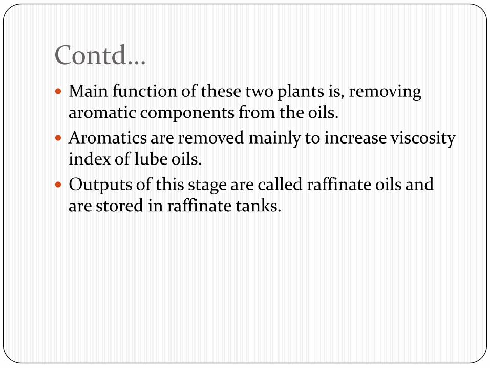
Contd… Main function of these two plants is, removing
aromatic components from the oils.
Aromatics are removed mainly to increase viscosity index of lube oils.
Outputs of this stage are called raffinate oils and are stored in raffinate tanks.
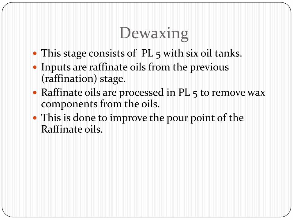
Dewaxing This stage consists of PL 5 with six oil tanks.
Inputs are raffinate oils from the previous (raffination) stage.
Raffinate oils are processed in PL 5 to remove wax components from the oils.
This is done to improve the pour point of the Raffinate oils.
Contd… Pour point of these oils is around 60 C to 150C.
Outputs of Dewaxing stage are called Dewaxed oils which are stored in Dewaxed tanks.
Hydro Finishing This stage consists of plant PL 6 with six tanks.
Inputs to this stage are dewaxed oils.
Dewaxed oils are processed in PL 6 to improve the colour.
This colour improvement is done by catalytic treatment using hydrogen.
contd… The outputs from Hydro finishing stage are called
lube oil based stock and are stored in finished lube oil tanks.
Mathematical model (Flow network optimization problem)
Flow network of lube oil section
Model consists of two phases.
Phase 1:
Flow chart of Phase-1 Objective: Finding the optimum feed rates.
Phase 2:
Flow chart of Phase-2 Objective :maximize the quantities of finished
lube oil products .

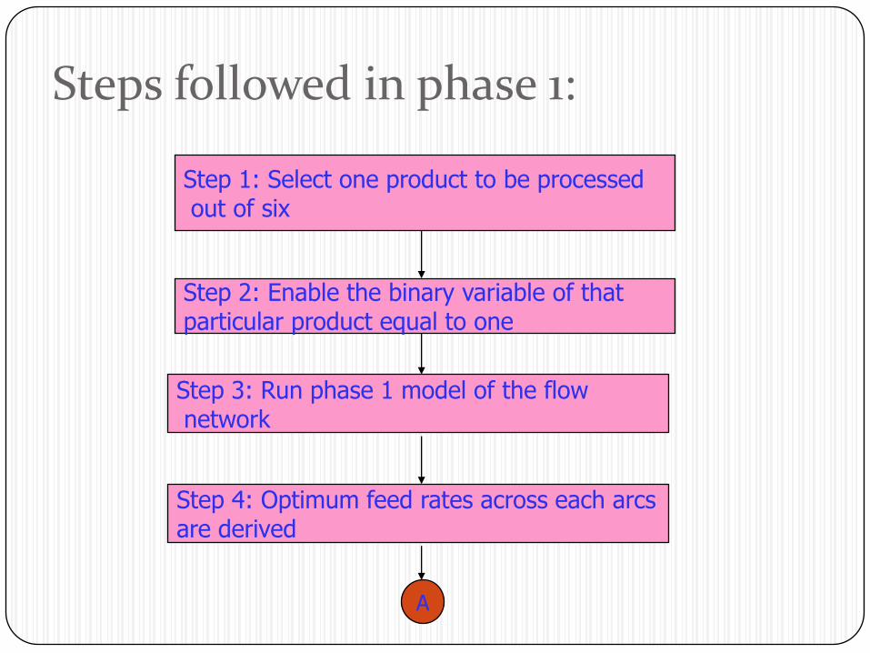
Steps followed in phase 1:
Step 1: Select one product to be processedout of six
Step 2: Enable the binary variable of that particular product equal to one
Step 3: Run phase 1 model of the flownetwork
Step 4: Optimum feed rates across each arcs are derived
A
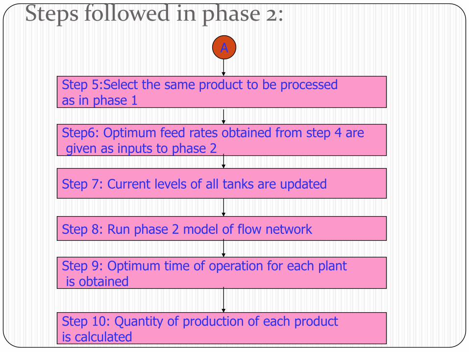
Steps followed in phase 2:
Step 5:Select the same product to be processed as in phase 1
Step6: Optimum feed rates obtained from step 4 aregiven as inputs to phase 2
Step 7: Current levels of all tanks are updated
Step 8: Run phase 2 model of flow network
Step 9: Optimum time of operation for each plantis obtained
Step 10: Quantity of production of each product is calculated
A
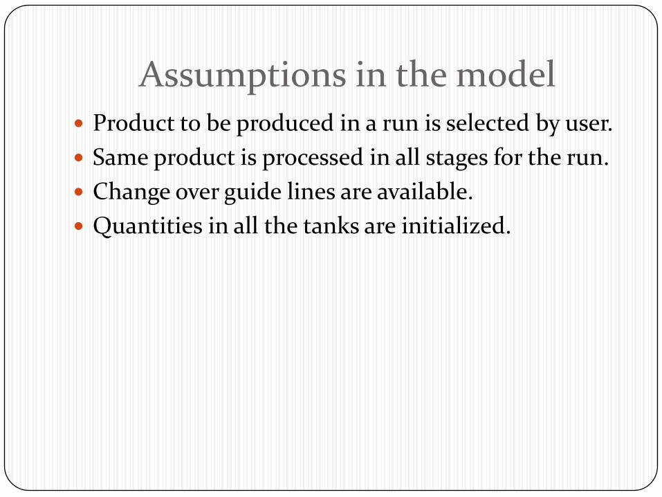
Assumptions in the model Product to be produced in a run is selected by user.
Same product is processed in all stages for the run.
Change over guide lines are available.
Quantities in all the tanks are initialized.
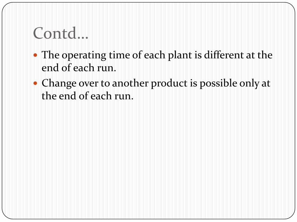
Contd… The operating time of each plant is different at the
end of each run.
Change over to another product is possible only at the end of each run.
constraints Feed rate:
-all tanks have acceptable limits of feed rate ranges for operation. -due to dynamic complexity involved, the system behaves differently for different set of feed rates in each plant at any given instance.

Storage tank capacity A plant can process a particular product only when
sufficient quantity of that product is available in the up stream tank.
Down stream tank should have sufficient space to accommodate drained material from the plant.
Notations used i-plant
j-tank
o-source
k-by-product
n-sink
f-feed rate
t-duration of time
Contd… bl,blm,blmn-binary variables
TPj = Tank levels at starting of the run.
TCj = Tank levels at end of the run.
Objective function
Phase-1
Maximize flow across the network
Max fn,o (1)
fn,o- flow between sink to source.
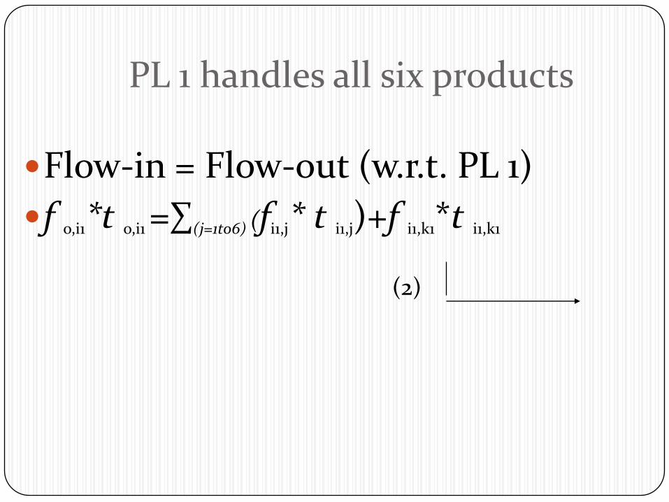
PL 1 handles all six products
Flow-in = Flow-out (w.r.t. PL 1)
f o,i1*t o,i1 =∑(j=1to6) (fi1,j* t i1,j)+f i1,k1*t i1,k1
(2)
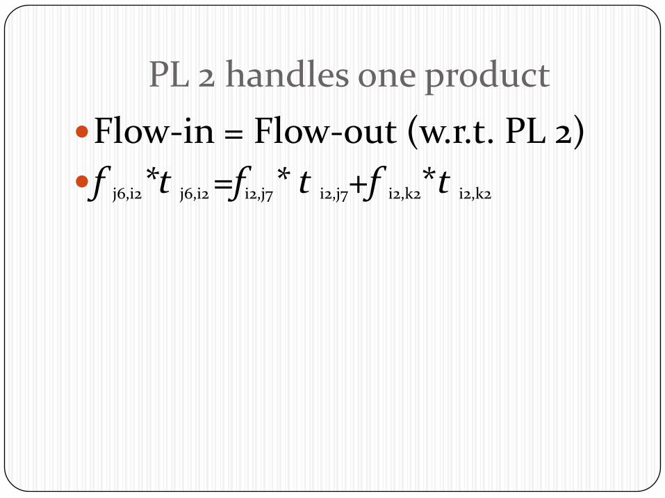
PL 2 handles one product
Flow-in = Flow-out (w.r.t. PL 2)
f j6,i2*t j6,i2 =fi2,j7* t i2,j7+f i2,k2*t i2,k2
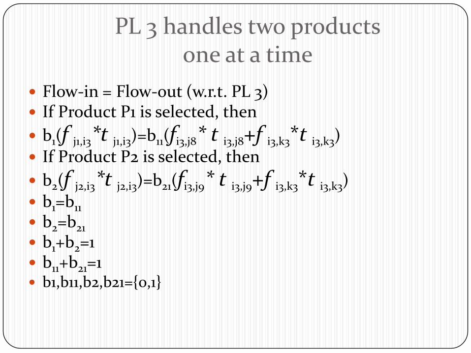
PL 3 handles two products one at a time
Flow-in = Flow-out (w.r.t. PL 3) If Product P1 is selected, then
b1(f j1,i3*t j1,i3)=b11(fi3,j8* t i3,j8+f i3,k3*t i3,k3)
If Product P2 is selected, then
b2(f j2,i3*t j2,i3)=b21(fi3,j9* t i3,j9+f i3,k3*t i3,k3)
b1=b11
b2=b21
b1+b2=1 b11+b21=1 b1,b11,b2,b21={0,1}
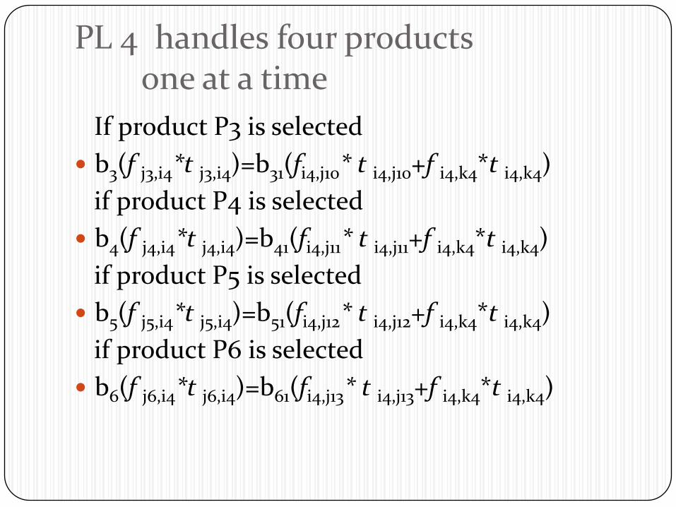
PL 4 handles four productsone at a time
If product P3 is selected
b3(f j3,i4*t j3,i4)=b31(fi4,j10* t i4,j10+f i4,k4*t i4,k4)
if product P4 is selected
b4(f j4,i4*t j4,i4)=b41(fi4,j11* t i4,j11+f i4,k4*t i4,k4)
if product P5 is selected
b5(f j5,i4*t j5,i4)=b51(fi4,j12* t i4,j12+f i4,k4*t i4,k4)
if product P6 is selected
b6(f j6,i4*t j6,i4)=b61(fi4,j13* t i4,j13+f i4,k4*t i4,k4)

contd… b3=b31
b4=b41
b5=b51
b6=b61
b3+b4+b5+b6=1
b31+b41+b51+b61=1
b3,b4,b5,b6,b31,b41,b51,b61 = 0,1
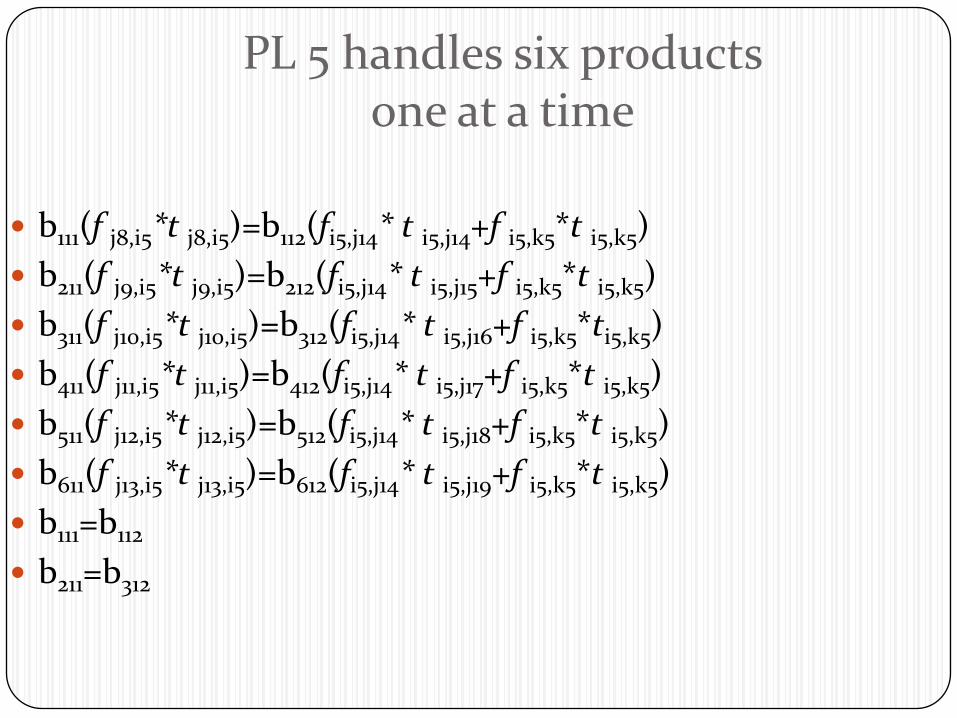
PL 5 handles six productsone at a time
b111(f j8,i5*t j8,i5)=b112(fi5,j14* t i5,j14+f i5,k5*t i5,k5)
b211(f j9,i5*t j9,i5)=b212(fi5,j14* t i5,j15+f i5,k5*t i5,k5)
b311(f j10,i5*t j10,i5)=b312(fi5,j14* t i5,j16+f i5,k5*ti5,k5)
b411(f j11,i5*t j11,i5)=b412(fi5,j14* t i5,j17+f i5,k5*t i5,k5)
b511(f j12,i5*t j12,i5)=b512(fi5,j14* t i5,j18+f i5,k5*t i5,k5)
b611(f j13,i5*t j13,i5)=b612(fi5,j14* t i5,j19+f i5,k5*t i5,k5)
b111=b112
b211=b312
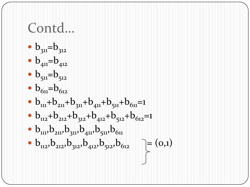
Contd… b311=b312
b411=b412
b511=b512
b611=b612
b111+b211+b311+b411+b511+b611=1
b112+b212+b312+b412+b512+b612=1
b111,b211,b311,b411,b511,b611
b112,b212,b312,b412,b512,b612 = (0,1)
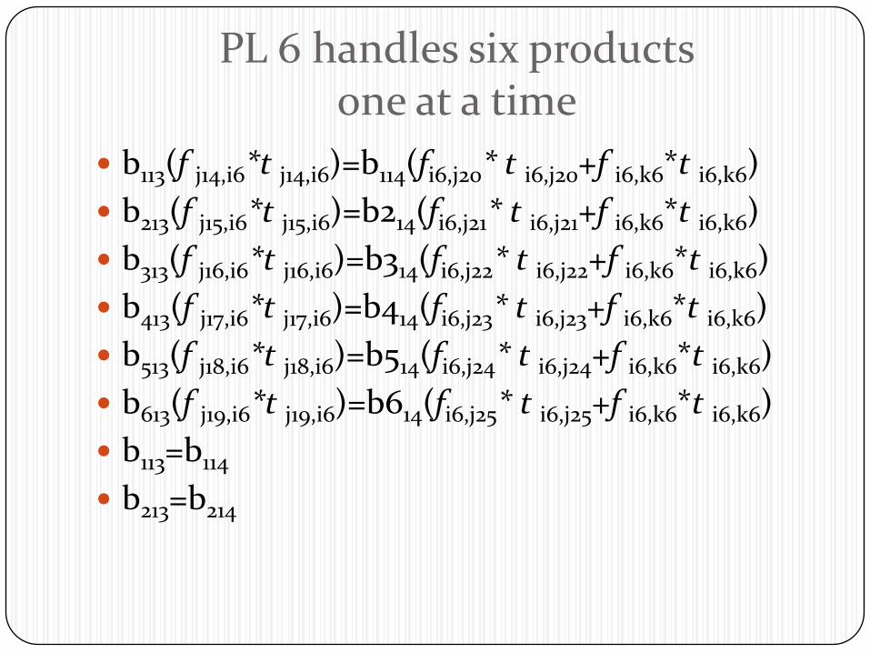
PL 6 handles six productsone at a time
b113(f j14,i6*t j14,i6)=b114(fi6,j20* t i6,j20+f i6,k6*t i6,k6)
b213(f j15,i6*t j15,i6)=b214(fi6,j21* t i6,j21+f i6,k6*t i6,k6)
b313(f j16,i6*t j16,i6)=b314(fi6,j22* t i6,j22+f i6,k6*t i6,k6)
b413(f j17,i6*t j17,i6)=b414(fi6,j23* t i6,j23+f i6,k6*t i6,k6)
b513(f j18,i6*t j18,i6)=b514(fi6,j24* t i6,j24+f i6,k6*t i6,k6)
b613(f j19,i6*t j19,i6)=b614(fi6,j25* t i6,j25+f i6,k6*t i6,k6)
b113=b114
b213=b214
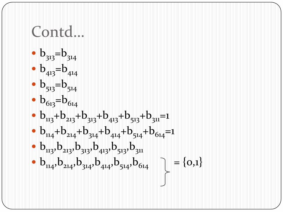
Contd… b313=b314
b413=b414
b513=b514
b613=b614
b113+b213+b313+b413+b513+b311=1
b114+b214+b314+b414+b514+b614=1
b113,b213,b313,b413,b513,b311
b114,b214,b314,b414,b514,b614 = {0,1}
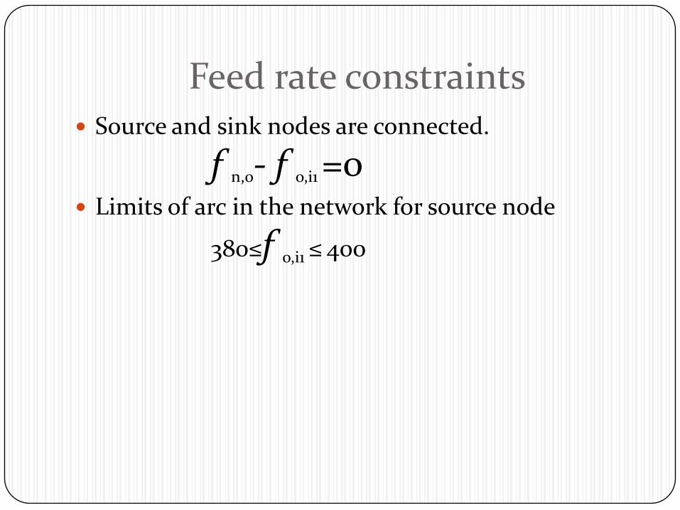
Feed rate constraints Source and sink nodes are connected.
f n,o- f o,i1 =0 Limits of arc in the network for source node
380≤f o,i1 ≤ 400
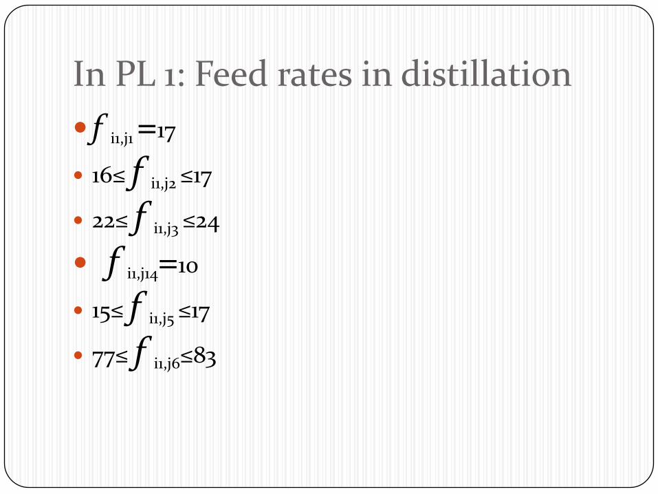
In PL 1: Feed rates in distillation
f i1,j1 =17
16≤ f i1,j2 ≤17
22≤ f i1,j3 ≤24
f i1,j14=10
15≤ f i1,j5 ≤17
77≤ f i1,j6≤83
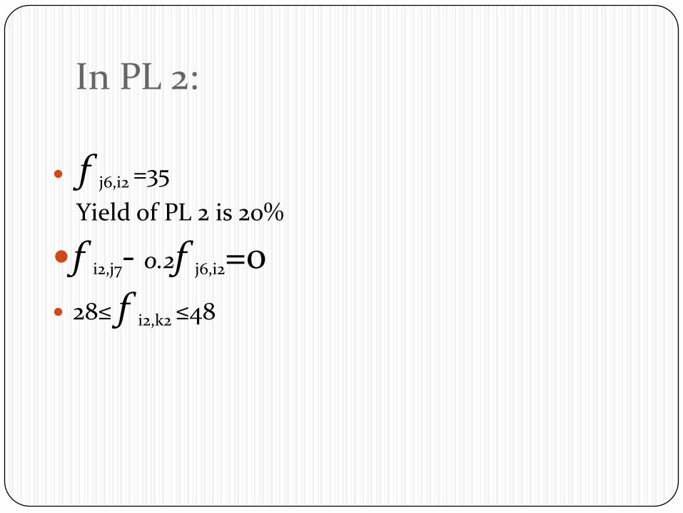
In PL 2:
f j6,i2 =35
Yield of PL 2 is 20%
f i2,j7- 0.2f j6,i2=0
28≤ f i2,k2 ≤48

In PL 3:
20≤ f j1,i3 ≤30
20≤ f j2,i3 ≤30
Yield of PL 3 is 65%
f i3,j8- 0.65f j1,i2=0f i3,j9- 0.65f j2,i3=0 7≤ f i3,k3≤10
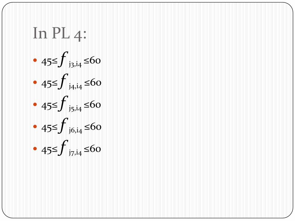
In PL 4:
45≤ f j3,i4 ≤60
45≤ f j4,i4 ≤60
45≤ f j5,i4 ≤60
45≤ f j6,i4 ≤60
45≤ f j7,i4 ≤60
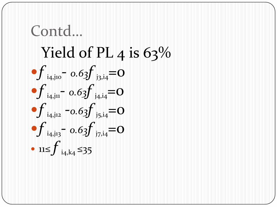
Contd…
Yield of PL 4 is 63%f i4,j10- 0.63f j3,i4=0f i4,j11- 0.63f j4,i4=0f i4,j12 -0.63f j5,i4=0f i4,j13- 0.63f j7,i4=0 11≤ f i4,k4 ≤35
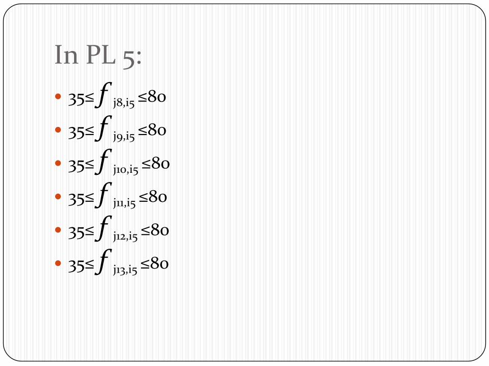
In PL 5:
35≤ f j8,i5 ≤80
35≤ f j9,i5 ≤80
35≤ f j10,i5 ≤80
35≤ f j11,i5 ≤80
35≤ f j12,i5 ≤80
35≤ f j13,i5 ≤80

Contd… Yield of PL 5 w.r.t. Products P1, P2, P3, P4, P5,
P6 : 78%, 74%, 73%, 71%, 72%, and 77% f i5,j14- 0.78f j8,i5=0 f i5,j15- 0.74f j9,i5=0 f i5,j16 -0.73f j10,i5=0 f i5,j17- 0.71f j11,i5=0 f i5,j18- 0.72f j12,i5=0 f i5,j19- 0.77f j13,i5=0 8≤ f i5,k5 ≤23
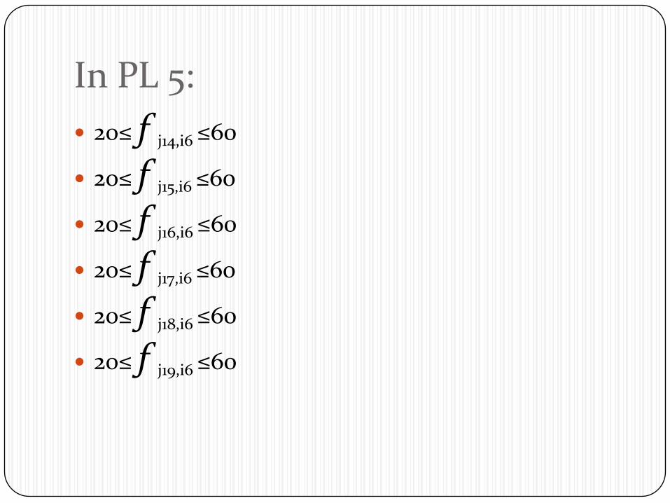
In PL 5:
20≤ f j14,i6 ≤60
20≤ f j15,i6 ≤60
20≤ f j16,i6 ≤60
20≤ f j17,i6 ≤60
20≤ f j18,i6 ≤60
20≤ f j19,i6 ≤60
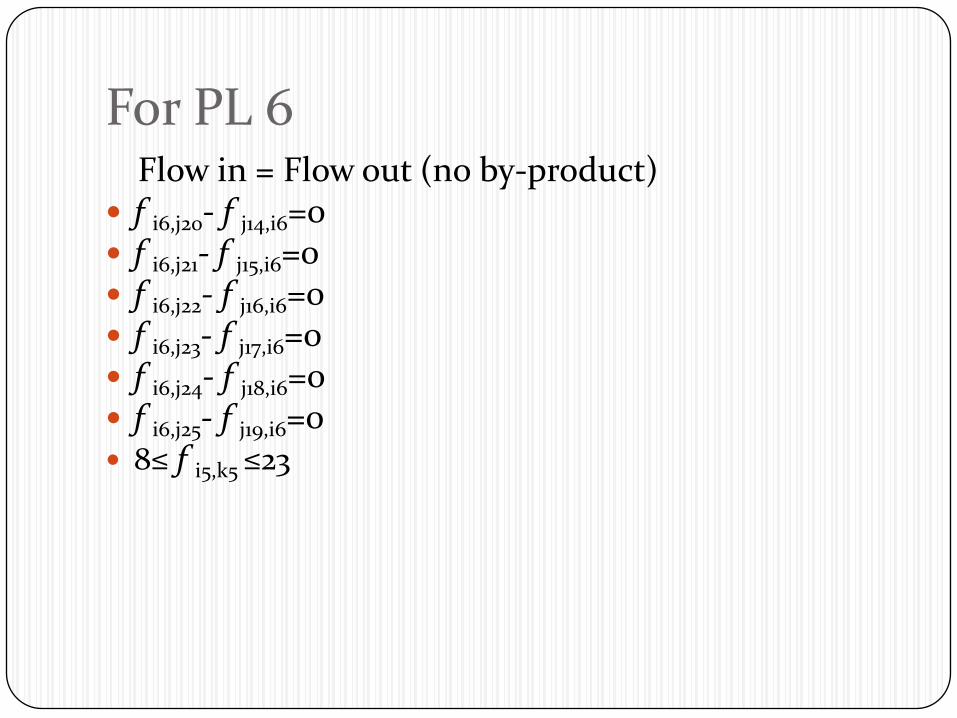
For PL 6Flow in = Flow out (no by-product)
f i6,j20- f j14,i6=0 f i6,j21- f j15,i6=0 f i6,j22- f j16,i6=0 f i6,j23- f j17,i6=0 f i6,j24- f j18,i6=0 f i6,j25- f j19,i6=0 8≤ f i5,k5 ≤23
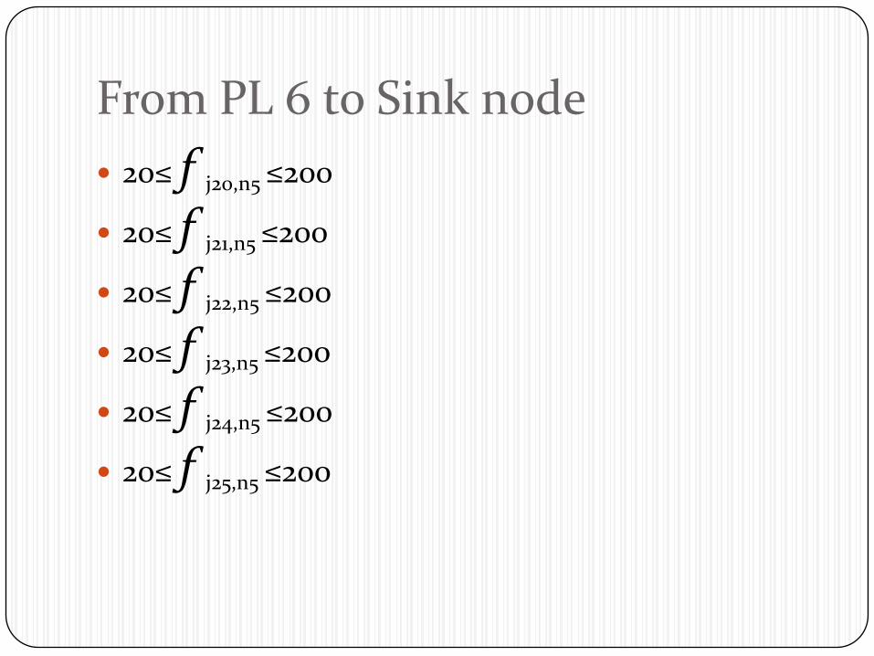
From PL 6 to Sink node
20≤ f j20,n5 ≤200
20≤ f j21,n5 ≤200
20≤ f j22,n5 ≤200
20≤ f j23,n5 ≤200
20≤ f j24,n5 ≤200
20≤ f j25,n5 ≤200
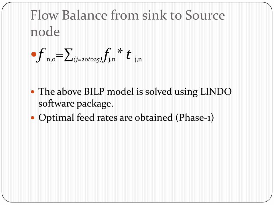
Flow Balance from sink to Source node
f n,o=∑(j=20to25) fj,n* t j,n
The above BILP model is solved using LINDO software package.
Optimal feed rates are obtained (Phase-1)
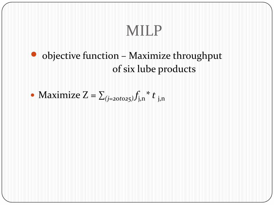
MILP
objective function – Maximize throughput
of six lube products
Maximize Z = ∑(j=20to25) fj,n* t j,n
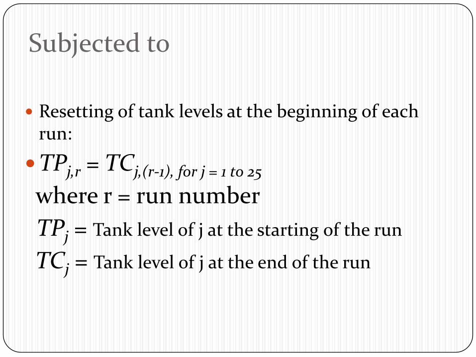
Subjected to
Resetting of tank levels at the beginning of each run:
TPj,r = TCj,(r-1), for j = 1 to 25
where r = run number
TPj = Tank level of j at the starting of the run
TCj = Tank level of j at the end of the run
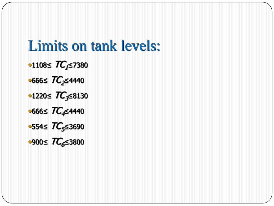
Limits on tank levels:•1108≤ TC1≤7380
•666≤ TC2≤4440
•1220≤ TC3≤8130
•666≤ TC4≤4440
•554≤ TC5≤3690
•900≤ TC6≤3800
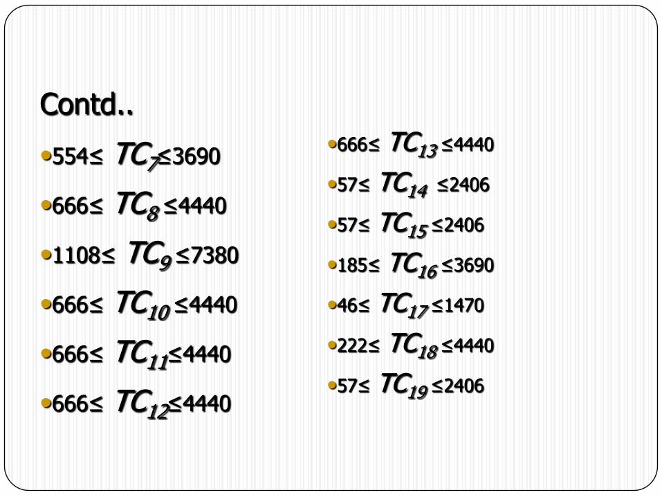
Contd..
•554≤ TC7≤3690
•666≤ TC8 ≤4440
•1108≤ TC9 ≤7380
•666≤ TC10 ≤4440
•666≤ TC11≤4440
•666≤ TC12≤4440
•666≤ TC13 ≤4440
•57≤ TC14 ≤2406
•57≤ TC15 ≤2406
•185≤ TC16 ≤3690
•46≤ TC17 ≤1470
•222≤ TC18 ≤4440
•57≤ TC19 ≤2406
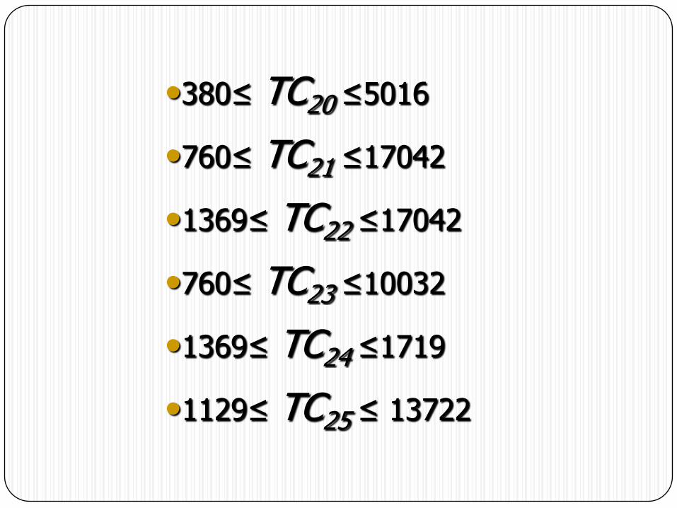
•380≤ TC20 ≤5016
•760≤ TC21 ≤17042
•1369≤ TC22 ≤17042
•760≤ TC23 ≤10032
•1369≤ TC24 ≤1719
•1129≤ TC25 ≤ 13722
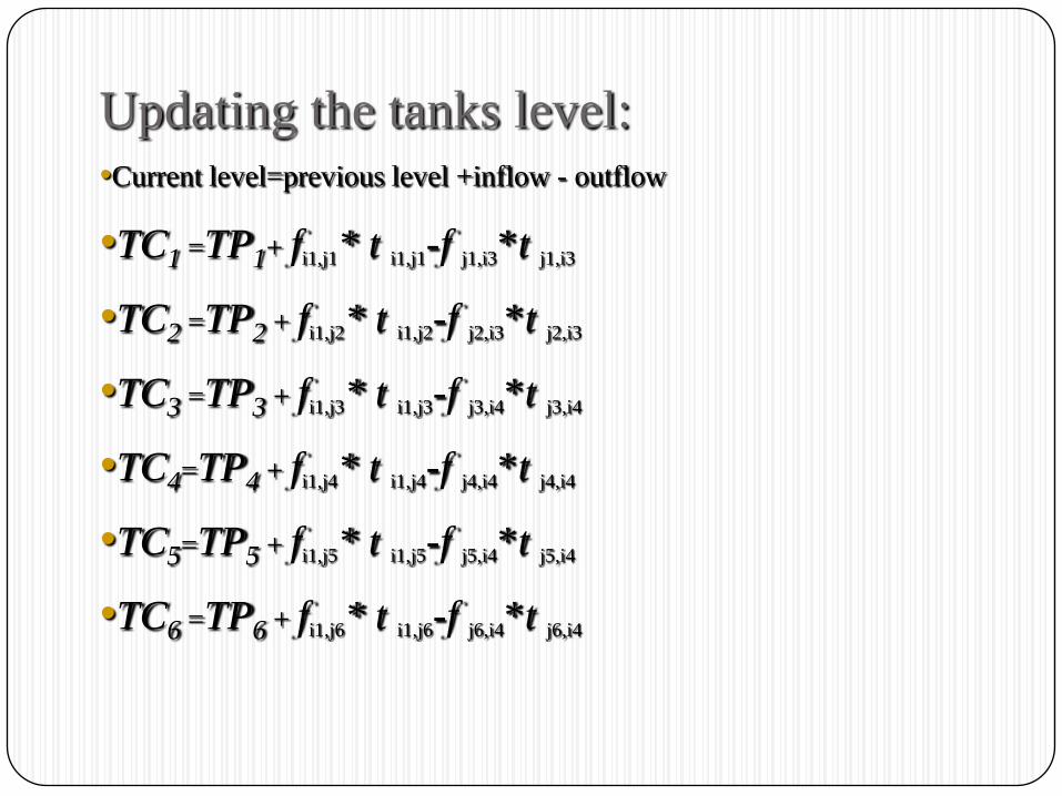
Updating the tanks level:•Current level=previous level +inflow - outflow
•TC1 =TP1+ fi1,j1* t i1,j1-f j1,i3*t j1,i3
•TC2 =TP2 + fi1,j2* t i1,j2-f j2,i3*t j2,i3
•TC3 =TP3 + fi1,j3* t i1,j3-f j3,i4*t j3,i4
•TC4=TP4 + fi1,j4* t i1,j4-f j4,i4*t j4,i4
•TC5=TP5 + fi1,j5* t i1,j5-f j5,i4*t j5,i4
•TC6 =TP6 + fi1,j6* t i1,j6-f j6,i4*t j6,i4

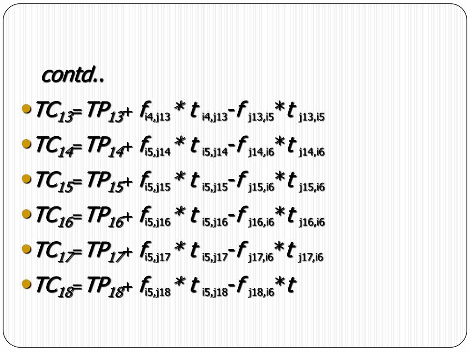
contd..
•TC7=TP7+ fi2,j7* t i2,j7-f j7,i4*t j7,i4
•TC8 =TP8+ fi3,j8* t i3,j8-f j8,i5*t j8,i5
•TC9=TP9+ fi4,j9* t i4,j9-f j9,i5*t j9,i5
•TC10=TP10+ fi4,j10* t i4,j10-f j10,i5*t j10,i5
•TC11=TP11+ fi4,j11* t i4,j11-f j11,i5*t j11,i5
•TC12=TP12+ fi4,j12* t i4,j12-f j12,i5
contd..
•TC13=TP13+ fi4,j13* t i4,j13-f j13,i5*t j13,i5
•TC14=TP14+ fi5,j14* t i5,j14-f j14,i6*t j14,i6
•TC15=TP15+ fi5,j15* t i5,j15-f j15,i6*t j15,i6
•TC16=TP16+ fi5,j16* t i5,j16-f j16,i6*t j16,i6
•TC17=TP17+ fi5,j17* t i5,j17-f j17,i6*t j17,i6
•TC18=TP18+ fi5,j18* t i5,j18-f j18,i6*t
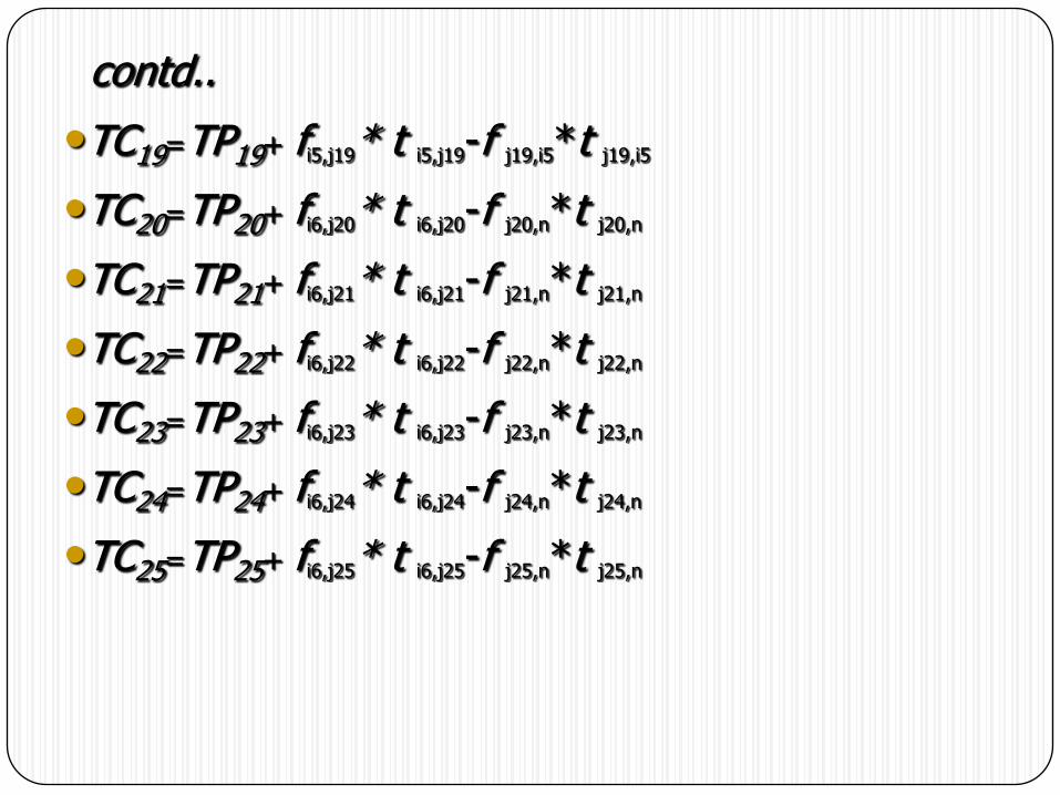
contd..
•TC19=TP19+ fi5,j19* t i5,j19-f j19,i5*t j19,i5
•TC20=TP20+ fi6,j20* t i6,j20-f j20,n*t j20,n
•TC21=TP21+ fi6,j21* t i6,j21-f j21,n*t j21,n
•TC22=TP22+ fi6,j22* t i6,j22-f j22,n*t j22,n
•TC23=TP23+ fi6,j23* t i6,j23-f j23,n*t j23,n
•TC24=TP24+ fi6,j24* t i6,j24-f j24,n*t j24,n
•TC25=TP25+ fi6,j25* t i6,j25-f j25,n*t j25,n
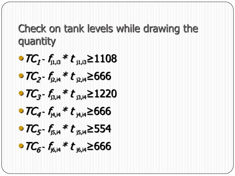
Check on tank levels while drawing the quantity
•TC1 - fj1,i3* t j1,i3≥1108
•TC2 - fj2,i4* t j2,i4≥666
•TC3 - fj3,i4* t j3,i4≥1220
•TC4 - fj4,i4* t j4,i4≥666
•TC5 - fj5,i4* t j5,i4≥554
•TC6 - fj6,i4* t j6,i4≥666
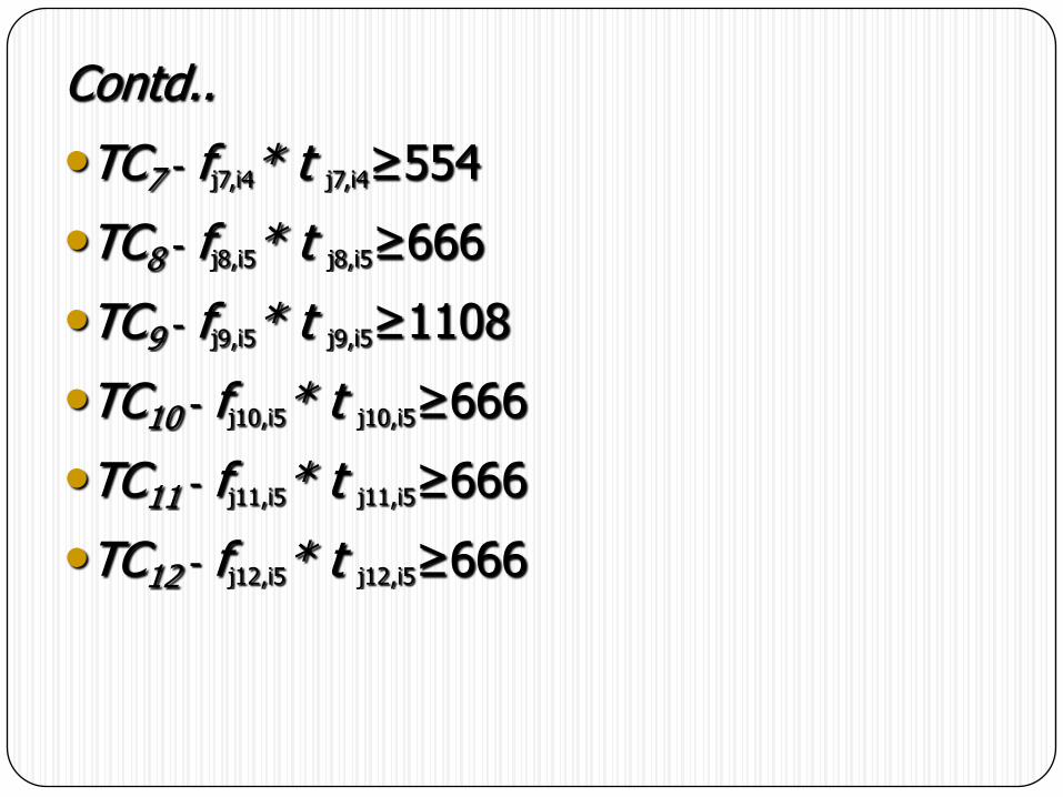
Contd..
•TC7 - fj7,i4* t j7,i4≥554
•TC8 - fj8,i5* t j8,i5≥666
•TC9 - fj9,i5* t j9,i5≥1108
•TC10 - fj10,i5* t j10,i5≥666
•TC11 - fj11,i5* t j11,i5≥666
•TC12 - fj12,i5* t j12,i5≥666

Contd…
•TC13 - fj13,i5* t j13,i5≥666
•TC14 - fj14,i6* t j14,i6≥57
•TC15 - fj15,i6* t j15,i6≥57
•TC16 - fj16,i6* t j16,i6≥185
•TC17 - fj17,i6* t j17,i6≥46
•TC18 - fj18,i6* t j18,i6≥222
•TC19 - fj19,i6* t j19,i6≥57
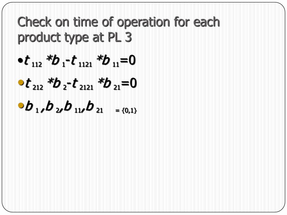
Check on time of operation for each product type at PL 3
•t 112 *b 1-t 1121 *b 11=0
•t 212 *b 2-t 2121 *b 21=0
•b 1 ,b 2,b 11,b 21 = {0,1}
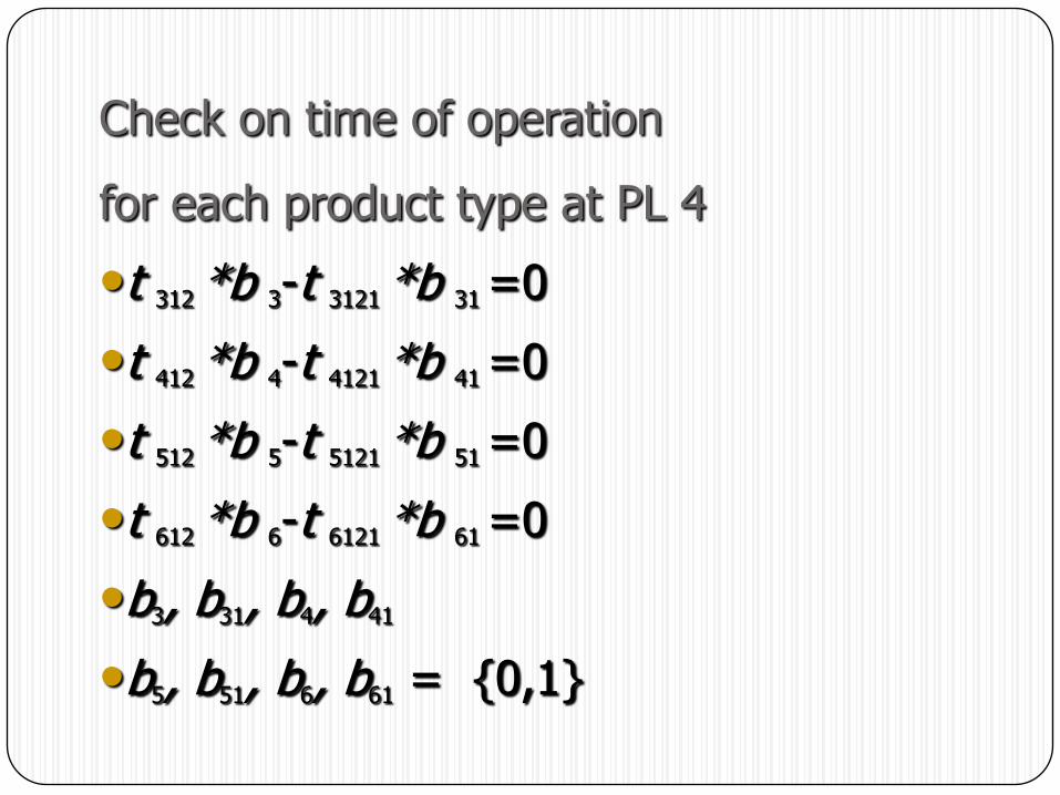
Check on time of operation
for each product type at PL 4
•t 312 *b 3-t 3121 *b 31 =0
•t 412 *b 4-t 4121 *b 41 =0
•t 512 *b 5-t 5121 *b 51 =0
•t 612 *b 6-t 6121 *b 61 =0
•b3, b31, b4, b41
•b5, b51, b6, b61 = {0,1}
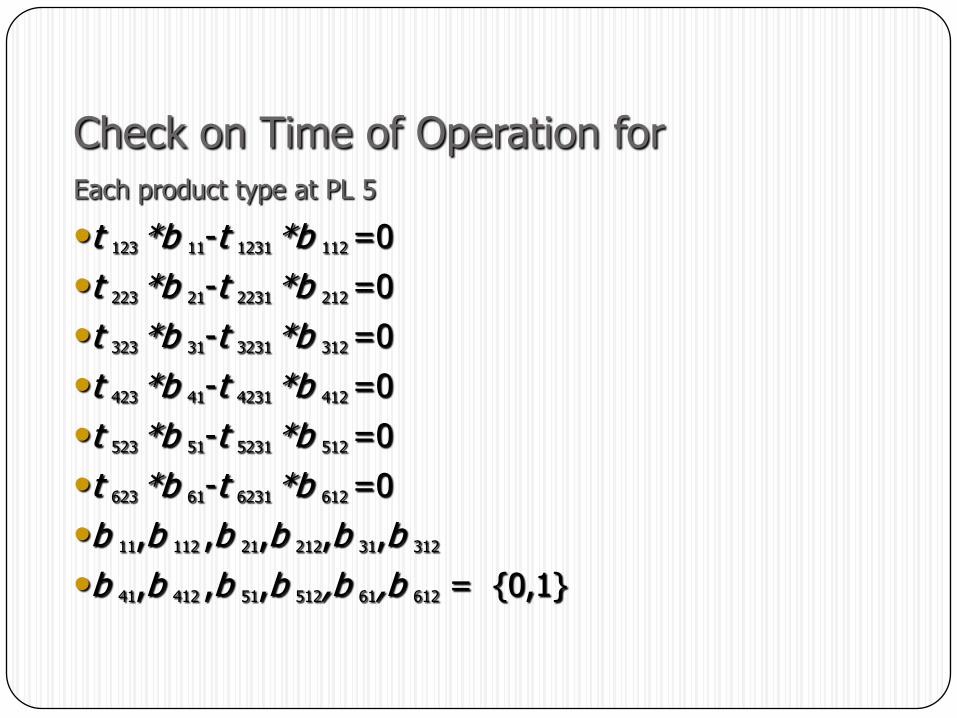
Check on Time of Operation forEach product type at PL 5
•t 123 *b 11-t 1231 *b 112 =0
•t 223 *b 21-t 2231 *b 212 =0
•t 323 *b 31-t 3231 *b 312 =0
•t 423 *b 41-t 4231 *b 412 =0
•t 523 *b 51-t 5231 *b 512 =0
•t 623 *b 61-t 6231 *b 612 =0
•b 11,b 112 ,b 21,b 212,b 31,b 312
•b 41,b 412 ,b 51,b 512,b 61,b 612 = {0,1}
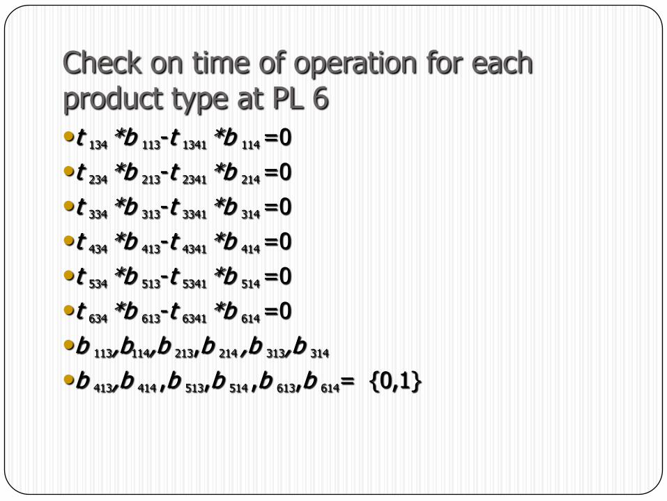
Check on time of operation for each product type at PL 6
•t 134 *b 113-t 1341 *b 114 =0
•t 234 *b 213-t 2341 *b 214 =0
•t 334 *b 313-t 3341 *b 314 =0
•t 434 *b 413-t 4341 *b 414 =0
•t 534 *b 513-t 5341 *b 514 =0
•t 634 *b 613-t 6341 *b 614 =0
•b 113,b114,b 213,b 214 ,b 313,b 314
•b 413,b 414 ,b 513,b 514 ,b 613,b 614= {0,1}

Check on time of operation for PL 1
•t 1-t 101=0
•t 1-t 201=0
•t 1-t 301=0
•t 1-t 401=0
•t 1-t 501=0
•t 1-t 601=0
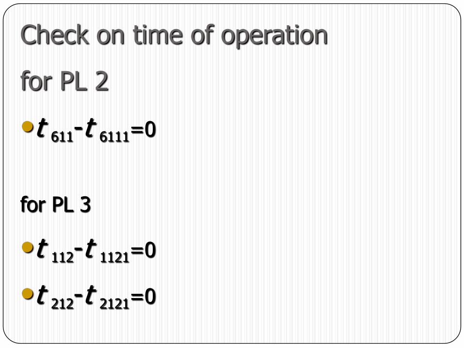
Check on time of operation
for PL 2
•t 611-t 6111=0
for PL 3
•t 112-t 1121=0
•t 212-t 2121=0
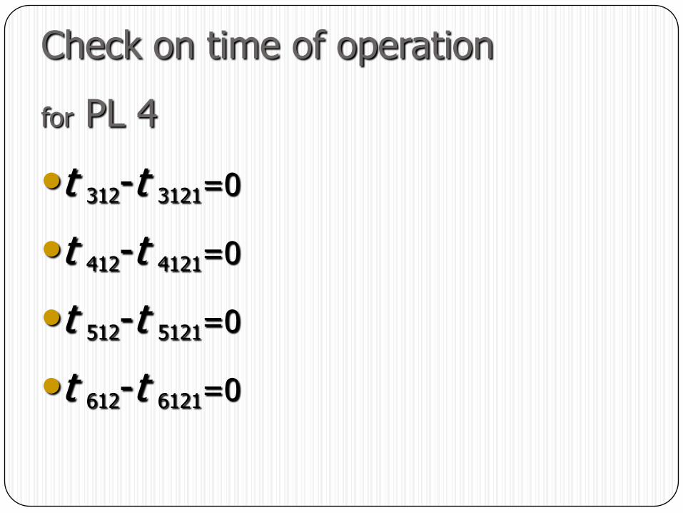
Check on time of operation
for PL 4
•t 312-t 3121=0
•t 412-t 4121=0
•t 512-t 5121=0
•t 612-t 6121=0
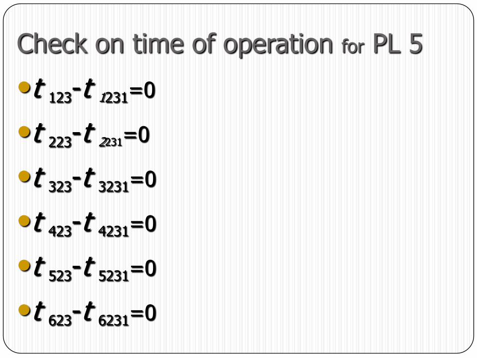
Check on time of operation for PL 5
•t 123-t 1231=0
•t 223-t 2231=0
•t 323-t 3231=0
•t 423-t 4231=0
•t 523-t 5231=0
•t 623-t 6231=0

Check on time of operation for PL 6
•t 134-t 1341=0
•t 234-t 2341=0
•t 334-t 3341=0
•t 434-t 4341=0
•t 534-t 5341=0
•t 634-t 6341=0
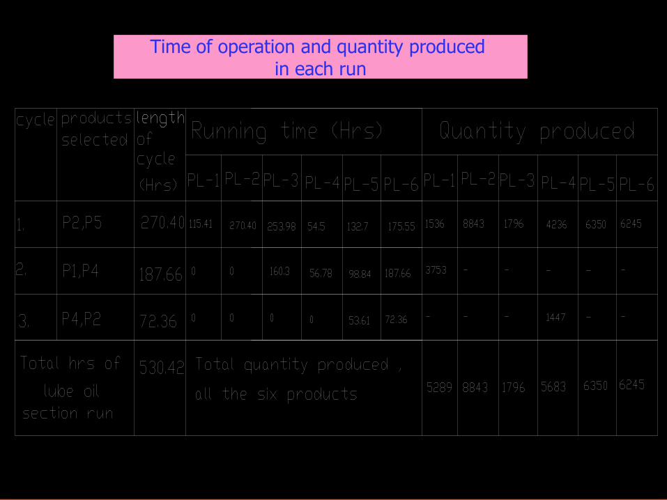
Time of operation and quantity produced in each run
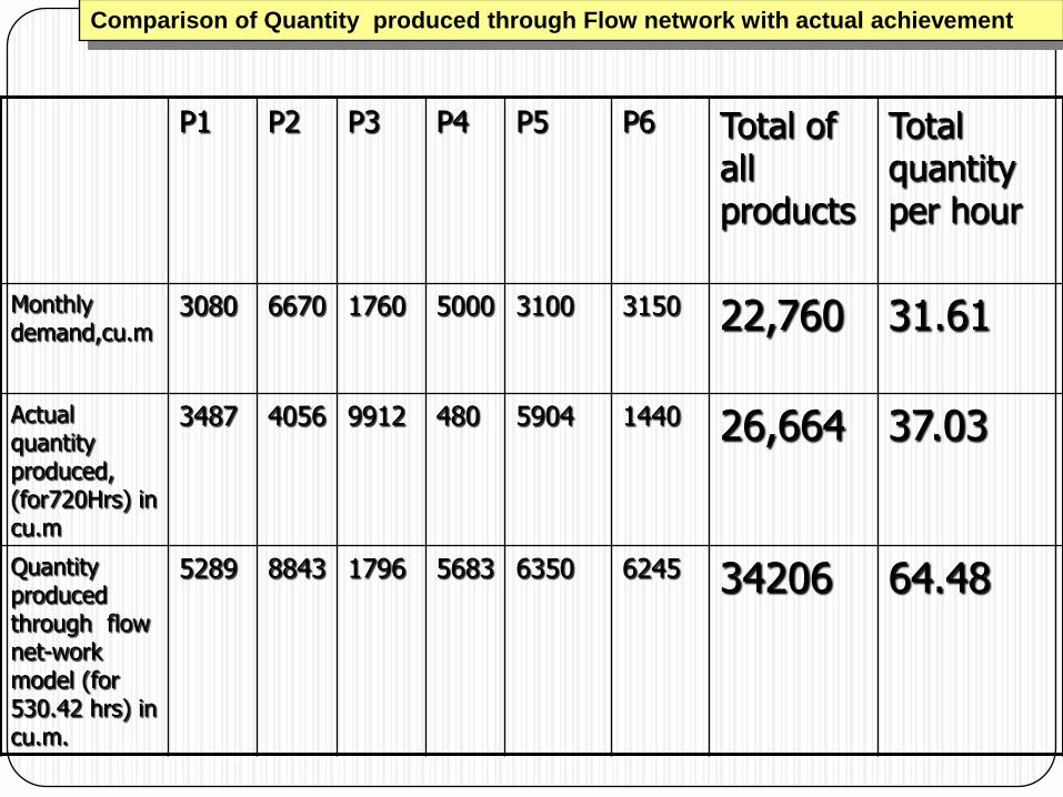
P1 P2 P3 P4 P5 P6 Total of all products
Total quantity per hour
Monthly demand,cu.m
3080 6670 1760 5000 3100 3150 22,760 31.61
Actual quantity produced, (for720Hrs) in cu.m
3487 4056 9912 480 5904 1440 26,664 37.03
Quantity produced through flow net-work model (for 530.42 hrs) in cu.m.
5289 8843 1796 5683 6350 6245 34206 64.48
Comparison of Quantity produced through Flow network with actual achievement