Embed Size (px)
Citation preview

Plant-wide Automation in the Water Industry
SIMATIC PCS 7, STEP 7, WinCC, TIA Portal
https://support.industry.siemens.com/cs/ww/en/view/109748869
Siemens Industry Online Support

Warranty and liability
Plant-wide Automation Water Industry Entry ID: 109748869, V1.0, 08/2017 2
S
iem
en
s A
G 2
01
7 A
ll ri
gh
ts r
ese
rve
d
Warranty and liability
Note The Application Examples are not binding and do not claim to be complete regarding the circuits shown, equipping and any eventuality. The Application Examples do not represent customer-specific solutions. They are only intended to provide support for typical applications. You are responsible for ensuring that the described products are used correctly. These Application Examples do not relieve you of the responsibility to use safe practices in application, installation, operation and maintenance. When using these Application Examples, you recognize that we cannot be made liable for any damage/claims beyond the liability clause described. We reserve the right to make changes to these Application Examples at any time without prior notice. If there are any deviations between the recommendations provided in these Application Examples and other Siemens publications – e.g. Catalogs – the contents of the other documents have priority.
We do not accept any liability for the information contained in this document. Any claims against us – based on whatever legal reason – resulting from the use of the examples, information, programs, engineering and performance data etc., described in this Application Example shall be excluded. Such an exclusion shall not apply in the case of mandatory liability, e.g. under the German Product Liability Act (“Produkthaftungsgesetz”), in case of intent, gross negligence, or injury of life, body or health, guarantee for the quality of a product, fraudulent concealment of a deficiency or breach of a condition which goes to the root of the contract (“wesentliche Vertragspflichten”). The damages for a breach of a substantial contractual obligation are, however, limited to the foreseeable damage, typical for the type of contract, except in the event of intent or gross negligence or injury to life, body or health. The above provisions do not imply a change of the burden of proof to your detriment. Any form of duplication or distribution of these Application Examples or excerpts hereof is prohibited without the expressed consent of the Siemens AG.
Security informa-tion
Siemens provides products and solutions with industrial security functions that support the secure operation of plants, systems, machines and networks. In order to protect plants, systems, machines and networks against cyber threats, it is necessary to implement – and continuously maintain – a holistic, state-of-the-art industrial security concept. Siemens’ products and solutions only form one element of such a concept. Customer is responsible to prevent unauthorized access to its plants, systems, machines and networks. Systems, machines and components should only be connected to the enterprise network or the internet if and to the extent necessary and with appropriate security measures (e.g. use of firewalls and network segmentation) in place. Additionally, Siemens’ guidance on appropriate security measures should be taken into account. For more information about industrial security, please visit http://www.siemens.com/industrialsecurity.
Siemens’ products and solutions undergo continuous development to make them more secure. Siemens strongly recommends to apply product updates as soon as available and to always use the latest product versions. Use of product versions that are no longer supported, and failure to apply latest updates may increase customer’s exposure to cyber threats. To stay informed about product updates, subscribe to the Siemens Industrial Security RSS Feed under http://www.siemens.com/industrialsecurity.

Table of Contents
Plant-wide Automation Water Industry Entry ID: 109748869, V1.0, 08/2017 3
S
iem
en
s A
G 2
01
7 A
ll ri
gh
ts r
ese
rve
d
Table of Contents Warranty and liability ................................................................................................... 2
1 Automation tasks in the water industry .......................................................... 4
1.1 Introduction ........................................................................................... 4 1.2 Typical plant types in the water industry .............................................. 6 1.3 Implementation of plant-wide automation ............................................ 9 1.4 Advantages ........................................................................................ 11
2 Product overview ............................................................................................. 12
2.1 SIMATIC engineering tools ................................................................ 12 2.2 Process visualization .......................................................................... 13 2.3 SIMATIC controllers ........................................................................... 14 2.4 Telecontrol .......................................................................................... 16 2.5 Solutions for energy management ..................................................... 17 2.6 Panel integration ................................................................................ 20 2.7 Water management system ............................................................... 21 2.8 Process instrumentation ..................................................................... 22
3 Specific solutions / approaches ..................................................................... 23
3.1 PCS 7 libraries ................................................................................... 23 3.2 Application examples ......................................................................... 25 3.3 Water-specific master data library and templates .............................. 25 3.3.1 Standards and guidelines ................................................................... 26 3.3.2 Water Control Module Types (WCMT) / Water Process Tag
Types (WPTT) .................................................................................... 27 3.3.3 Water Equipment Module Templates (WEMT) .................................. 27 3.3.4 Water Unit Templates (WUT) ............................................................. 27 3.3.5 Control strategy of the water-specific templates ................................ 28
4 Guidelines for planning and configuring ...................................................... 30
4.1 Engineering ........................................................................................ 30 4.2 Naming convention ............................................................................. 33 4.3 P&ID diagram ..................................................................................... 35 4.4 Process control and operation ........................................................... 40 4.5 Communication .................................................................................. 43
5 Appendix .......................................................................................................... 44
5.1 Glossary ............................................................................................. 44 5.2 Service and Support ........................................................................... 45 5.3 Links and Literature ............................................................................ 45 5.4 Change documentation ...................................................................... 47

1 Automation tasks in the water industry
Plant-wide Automation Water Industry Entry ID: 109748869, V1.0, 08/2017 4
S
iem
en
s A
G 2
01
7 A
ll ri
gh
ts r
ese
rve
d
1 Automation tasks in the water industry
1.1 Introduction
In the widely distributed systems of the water industry, the predominantly automated operation of plants is considered state of the art. Technical difficulties are encountered when implementing automated operation due to the complexity of the water management system itself. Compared to process engineering plants in other industries, such as the chemical industry, the number of actuators, sensors, measuring instruments and control loops is similarly high.
This document gives you an overview of the standardized and plant-wide automation solutions from Siemens.
Challenge
The standardization of automation engineering is a major challenge due to the various process actions, procedures, devices and elevated plant configuration requirements. This also includes the customized selection and dimensioning of suitable products for the respective application. Siemens supports you in selecting the right hardware and software for your plant-wide automation solution and is a reliable service partner in the water industry sector.
Approach with plant-wide automation in the water industry
Plant-wide automation in the water industry leads to a sustainable success throughout the entire life cycle of the process plant including planning and services. Particular sectors include:
Drinking water, desalination, water transportation
Wastewater, water purification, industrial water
Irrigation, pumping stations, dams
Defensive structures, waterways, locks
Dikes, flood protection
Figure 1-1 Water industry sectors
Water transportation
Drinking waterDesalination
Wastewater

1 Automation tasks in the water industry
Plant-wide Automation Water Industry Entry ID: 109748869, V1.0, 08/2017 5
S
iem
en
s A
G 2
01
7 A
ll ri
gh
ts r
ese
rve
d
Automation mainly includes the following elements:
Controllers of actuators, motors, valves, flaps, motor valves and servo-drives
Detection of process values such as flow, pressure, temperature, level and substance analysis
Control and monitoring of dynamic processes and circuits
Display of processes and plant state
Centralized, distributed and local plant control from the field to the web
You can find further information on the automation engineering in the water industry at:
https://w3.siemens.com/mcms/water-industry/en/process-products-systems/Pages/automation-engineering.aspx
Requirements of the automation solution
In the water industry, plants require a high level of automation. Further requirements for continuous and safe plant operation also include:
Simple planning
Fast implementation in engineering
Preapproved and safe commissioning
Flexibility and expandability
Scalability of the components to the plant size
High level of software and hardware standardization
Integration of third party and old systems
High plant reliability and integrity
Robust design of automation hardware mechanics / electronics
Reliable communication over long distances
Uniform control and representation of plant data
Long-term archiving of measurement and operating data
Easy upgrading to new automation software versions
Future-proof thanks to long life cycles and suitable replacement components
Further information
You can find further information on the topic of automation in the water industry by accessing the sector-specific pages on the PCS 7 website:
https://w3.siemens.com/mcms/water-industry/en/Pages/water-industry.aspx

1 Automation tasks in the water industry
Plant-wide Automation Water Industry Entry ID: 109748869, V1.0, 08/2017 6
S
iem
en
s A
G 2
01
7 A
ll ri
gh
ts r
ese
rve
d
1.2 Typical plant types in the water industry
The different water management systems can be fully automated with Siemens products. The following schematic representations of typical plants cover large parts of the water industry and provide guidance for your own plant.
Figure 1-2 Schematic representation of a desalination plant

1 Automation tasks in the water industry
Plant-wide Automation Water Industry Entry ID: 109748869, V1.0, 08/2017 7
S
iem
en
s A
G 2
01
7 A
ll ri
gh
ts r
ese
rve
d
Figure 1-3 Schematic representation of a drinking water plant
Figure 1-4 Schematic representation of water transportation

1 Automation tasks in the water industry
Plant-wide Automation Water Industry Entry ID: 109748869, V1.0, 08/2017 8
S
iem
en
s A
G 2
01
7 A
ll ri
gh
ts r
ese
rve
d
Figure 1-5 Schematic representation of a wastewater treatment plant

1 Automation tasks in the water industry
Plant-wide Automation Water Industry Entry ID: 109748869, V1.0, 08/2017 9
S
iem
en
s A
G 2
01
7 A
ll ri
gh
ts r
ese
rve
d
Figure 1-6 Schematic representation of an irrigation system
1.3 Implementation of plant-wide automation
Plant-wide automation is the basis for a smooth, uniform and standardized solution for water management systems. Siemens supports you in the area of project planning with customized products such as:
SIMATIC PCS 7 process control system
SCADA system: SIMATIC WinCC , WinCC Professional
Engineering tools: COMOS, SIMATIC PCS 7, TIA Portal
This document focuses on the following points:
Product overview
Overview of the water-specific automation solutions – Specific solutions / approaches
Description of the PCS 7 Water Templates as a template for automation solutions – Water-specific master data library and templates
Introduction to the requirements and guidelines for standardized automation solutions in the water industry – Guidelines for planning and configuring

1 Automation tasks in the water industry
Plant-wide Automation Water Industry Entry ID: 109748869, V1.0, 08/2017 10
S
iem
en
s A
G 2
01
7 A
ll ri
gh
ts r
ese
rve
d
Selecting suitable hardware and software
In the German Guidelines on Water and Sewage Treatment (ATV), the plants are described, treated and operated as process plants. Plants in the water industry are process plants with many package units (machine-oriented automation), which are fully integrated in PCS 7 from the field to the web. For process monitoring in small to medium-sized plants, it is possible to use PCS 7 or even a SCADA system with WinCC or TIA Portal.
In the following table, you can find the different performance features of the Siemens SIMATIC PCS 7 and TIA Portal automation products and their general use.
Table 1-1 Differences in performance features between SIMATIC PCS 7 and TIA Portal
Property SIMATIC PCS 7 TIA Portal / WinCC+STEP 7
Application area Process automation, DCS Machine-oriented automation, PLC
Use for Continuous processes, remote control technology incl. medium / low voltage switchgear with local and widely distributed plants for the monitoring of drives with local panel control, local control systems as well as local, central and / or regional control rooms via multi-user control in a multi-server architecture
SIMATIC PCS 7 is also available as a virtualized solution.
Discrete processes and machines with spatially limited distributed measuring points, drives and low voltage switchgear systems, including local control systems and panel control, which are controlled and monitored via a local and / or central control room using a single-user station or a client-server architecture.
WinCC is also available as a visualized solution.
Controller S7-300, S7-400, PA CPU 410, S7-1200, S7-1500
S7-300, S7-400, S7-1200, S7-1500
Changes during operation (CiR functionality)
Yes (S7-400, S7-410) No
Programming with CFC
Yes Yes*
Advanced Process Library (APL)
Yes No
Industry Library (IL) Yes No
Panel connection, e.g. SIMATIC Basic / Comfort Panel
Yes** Yes
Highly available (so called hot standby)
Yes (S7-400, S7-410) No
* Only in STEP 7 with additional optional package S7-CFC for S7-300 and S7-400
** TIA Portal Advanced Engineering: The engineering of the measured values takes place in CFC based on the IL. TIA Portal is required for graphical display on the panels.
The selection of the automation products for a water management system is based on the requirements of the respective system. For further information on the technical features of the Siemens automation solutions, please refer to the chapter Product overview.

1 Automation tasks in the water industry
Plant-wide Automation Water Industry Entry ID: 109748869, V1.0, 08/2017 11
S
iem
en
s A
G 2
01
7 A
ll ri
gh
ts r
ese
rve
d
1.4 Advantages
By using a Siemens standardized solution you achieve the following advantages in the automation of functions, sections and complete plants:
Standardization through unified program structures provide time and cost savings during the
– planning and conception phase
– implementation phase
– entire operation time and migration phase to new SW and HW versions
Safe monitoring with uniform operator control and monitoring from the field to the web
Secure data transfer
Uniform and simple understanding of the entire automation system
– Shorter operator familiarization periods
– Shorter and cost-optimized training periods
– Simple and cost-optimized expansion of the existing system
Lifecycle guarantee with short maintenance and service times
– Lower maintenance costs and system downtime
– Fast, flexible and reliable support by Siemens
2 Product overview
Plant-wide Automation Water Industry Entry ID: 109748869, V1.0, 08/2017 12
S
iem
en
s A
G 2
01
7 A
ll ri
gh
ts r
ese
rve
d
2 Product overview Siemens offers tools and software solutions for use as a scalable SCADA system with WinCC Professional (TIA Portal) or WinCC, also the SIMATIC PCS 7 process control system. In this chapter, you will be introduced to some of the Siemens product families and their use in the water / wastewater sectors.
2.1 SIMATIC engineering tools
Depending on the application and requirements, you can use differently powerful SIMATIC controllers and engineering tools for your water management system. Thereby a distinction is made between a distributed operation that is at machine level, local or plant-wide.
SIMATIC PCS 7
With the SIMATIC PCS 7 process control system, you can automate customized solutions from the smallest to the most complex water management systems as well as small operating units (plant sections). SIMATIC PCS 7 is flexibly scalable from a small single-user system with more than 50 measuring points and drives, right up to 1280,000 in a multi-user system including redundancy. The max. number of configurable messages is 200,000 per server / single-user station.
Consistency in data management, secure communication as well as simple configuration and high performance put the PCS 7 together with the SIMATIC PA CPU-410-5S / H / E at the heart of your water management system. Existing control systems by third party manufacturers can also be upgraded step by step or even migrated to SIMATIC PCS 7 during operation. To help you store your measured values and messages, PCS 7 offers the SIMATIC Process Historian – a central long-term archiving system.
Siemens also supports the integration of Energy Manager Pro as an option.
Outdoor stations are integrated into the process control system of widely distributed systems such as pipelines or water supply and distribution plants via system-compliant telecontrol systems (simultaneous protocol type: SINAUT ST7, IEC 60870-5-101 / 103 / 104, DNP3, Modbus) using TeleControl for PCS 7. You can find further relevant information in the chapter Telecontrol.
It is also possible to operate and monitor local and widely distributed plants energetically. Power Control for PCS 7 offers the right solution for medium and low voltage switchgear systems for integration via Industrial Ethernet, PROFINET and PROFIBUS DP.
You can find further information on energy management with Power Control Library in the chapter: PCS 7 libraries.
For a quick introduction, you can access the PCS 7 automation templates that were specifically created for the water industry. You can find a compact overview in the chapter Water-specific master data library and templates.
COMOS – Uninterrupted flow of information
Thanks to the COMOS Plant Engineering Software, you can implement your water management system in a holistic manner throughout the entire life cycle. The uniform data platform of COMOS enables a seamless information flow of project-relevant data and efficient mass data engineering across all project phases. COMOS manages all the plant data and the corresponding documentation on a single integrated data platform, right from the initial planning phase. This means that every operator can access up-to-date information at any time and at any place.

2 Product overview
Plant-wide Automation Water Industry Entry ID: 109748869, V1.0, 08/2017 13
S
iem
en
s A
G 2
01
7 A
ll ri
gh
ts r
ese
rve
d
Integrated engineering with COMOS and SIMATIC PCS 7
You can easily transfer data from COMOS to SIMATIC PCS 7 without errors and thus automatically generate the entire plant structure in the control system. With just one data platform, project participants from different trades can plan the areas of your plant in parallel. This saves crucial time during engineering and when implementing your automation solution.
Changes and adaptations made in SIMATIC PCS 7 during the operating phase can be played back in COMOS at the push of a button. As a result, any changes made are automatically copied to the entire system documentation. The data exchange between the two systems connects the worlds between engineering and automation and allows you to digitalize your water management system.
SIMATIC STEP 7
The Siemens SIMATIC STEP 7 engineering system is a unique integrated automation solution for your plant, allowing you to assign parameters, program and test the controllers. With STEP 7, you can configure the controller families SIMATIC S7-300 and S7-400 and implement plant-wide distributed process automation.
TIA Portal
The Totally Integrated Automation Portal (TIA Portal) is a central data management solution with a uniform operating concept and integrated services, which helps you in the engineering and commissioning phases of your machine-level automation solution. For these local, small to medium-sized tasks in the water industry you can rely on the SIMATIC S7-300 and S7-1200 controllers. Besides central engineering with the TIA Portal, they also enable you to easily connect SIMATIC HMI panels.
2.2 Process visualization
For process visualization, Siemens offers customized solutions ranging from the smallest of applications to large systems with redundantly designed servers.
SIMATIC PCS 7 Operator System
In PCS 7, the operator station is the central station for monitoring and controlling a PCS 7 plant. The PCS 7 system is monitored and operated in the process management system by means of process pictures. Faceplates provide you information on the status of individual components and technological functions. The information you need for monitoring and operation is rounded up by trends for the temporal signal sequence, message lists, alarm lists and archive information.
The OS is configured on the Engineering Station (ES). The configuration data of the OS is stored and managed centrally on the engineering station.
The operator system is scalable with regard to quantity structure and functionality. From the single-user station to the distributed multi-user system and web solutions.
For further information, please refer to:
http://w3.siemens.com/mcms/process-control-systems/en/distributed-control-system-simatic-pcs-7/simatic-pcs-7-system-components/operator-system/Pages/operator-system.aspx

2 Product overview
Plant-wide Automation Water Industry Entry ID: 109748869, V1.0, 08/2017 14
S
iem
en
s A
G 2
01
7 A
ll ri
gh
ts r
ese
rve
d
SIMATIC PCS 7 Advanced Process Graphics
Increasingly complex process plants pose an enormous challenge to operating personnel. For this reason, it is important for relevant process information to be available and for plant conditions and operational parameters to be displayed in the control room in a clear, simple and well-arranged manner. Only in this way can the correct decisions be made and the appropriate measures taken quickly. For effective process control, APG offer hybrid views, trend curves, and Kiviat charts that provide information instead of data to operators.
For further information, please refer to:
http://w3.siemens.com/mcms/process-control-systems/en/distributed-control-system-simatic-pcs-7/simatic-pcs-7-technologies/Efficient-Process-Control/Pages/Advanced-Process-Graphics.aspx
SIMATIC WinCC (SCADA System)
Siemens offers the right SIMATIC software for the SCADA area. From a comprehensive solution as a PC-based multi-user system with SCADA functionality for the machine level right to the open and scalable SCADA system SIMATIC WinCC, which has been tried and tested in the market for many years.
SIMATIC WinCC is scalable with regard to quantity structure and functionality. From the single-user station to the distributed multi-user system and web solutions.
For an overview of the process visualization functions in the SCADA environment with WinCC, please refer to:
http://w3.siemens.com/mcms/human-machine-interface/en/visualization-software/scada/simatic-wincc/Pages/default.aspx
SIMATIC WinCC Professional(TIA Portal)
Almost the entire range of SIMATIC operator panels can be configured with SIMATIC WinCC Professional (TIA Portal), the successor to SIMATIC WinCC flexible. The functionality covers both visualization tasks on the machine level and SCADA applications on PC-based multi-user systems.
Further information
http://w3.siemens.com/mcms/automation-software/en/tia-portal-software/wincc-tia-portal/Pages/default.aspx
2.3 SIMATIC controllers
The versatile SIMATIC controllers with their enhanced performance spectra allow you to automate your system in a customized and optimal manner. In doing so, you can use the controllers for local and / or distributed applications and combine them to achieve a uniform SIMATIC automation solution for your entire system.
SIMATIC S7-300: An all-rounder for all processes
The SIMATIC S7-300 controllers are versatile and compact controllers, which are characterized by flexible parameter assignment and powerful performance. A local and distributed automation solution can be implemented with up to 256 integrated inputs / outputs and up to 65336 distributed inputs / outputs. The PROFINET interface allows you to easily connect the controller and the data exchange with the control system and the I / Os. Comprehensive engineering with SIMATIC STEP 7 minimizes the costs of operation, maintenance and documentation.
2 Product overview
Plant-wide Automation Water Industry Entry ID: 109748869, V1.0, 08/2017 15
S
iem
en
s A
G 2
01
7 A
ll ri
gh
ts r
ese
rve
d
SIMATIC S7-400: High performance and security for system solutions
The controllers of the SIMATIC S7-400 family are characterized by their large memory, up to 65336 inputs and outputs and extremely high speed. Thanks to their high performance, the S7-400 controllers are used primarily for data-intensive tasks – for example, you can use the S7-400 to centrally control and process the data of many smaller units and distributed areas with local controllers. With their state-of-the-art technology and maximum cost-effectiveness, they are ideal for system solutions in water treatment plants – even in extreme environments – and can also be used for high-availability and safety-oriented applications, if necessary.
The highly available SIMATIC S7-400H provides hardware redundancy (hot standby) for uninterruptible processes, such as the ones that are often required in desalination plants and important pump stations.
SIMATIC PA CPU410: Flexible and uninterruptible
The SIMATIC PA CPU410 controller is best suited for new systems and is ideal if the performance requirements of your automation solution have to be scaled to the increasing requirements. Apart from the familiar SIMATIC features, such as great ruggedness and minimal downtimes, the controller is characterized by its top-level flexibility. The integrated PROFINET interfaces allow fieldbuses to be designed in a simple and redundant manner.
The controller is generally delivered with the maximum computing and storage capacity level, and can be scaled to the required performance (number of process objects) by means of a system expansion card (SEC). As from the PCS 7 V8.1 version, it is possible to update individual block types and install new expansion modules without causing an interruption. This means that at a later date you can expand your plant flexibly during operation with regard to its performance and scale.
SIMATIC S7-1200: Modular and compact
In the class of compact controllers, the SIMATIC S7-1200 offers the necessary performance for smaller yet highly precise automation tasks. The SIMATIC S7-1200 controller offers up to 30 signal, communication and technology modules as an expansion, integrated I / O interfaces, integrated communication with HMI panels, and a simple PROFINET connection to the control system. In combination with the easy-to-use and integrated TIA Portal engineering system, you can automate your plant simply, compactly and modularly.
SIMATIC S7-1500: Performant and flexible
The SIMATIC S7-1500 is suitable for medium to large automation tasks. Thanks to fast signal processing, it meets the high demands on response times and fast high-precision control. The integrated PROFINET interfaces allow you to easily integrate the controller into your existing control system and also to implement distributed automation solutions. The engineering is carried out uniformly via the TIA Portal and allows simple implementation of logics, data management and user interface. In addition to the integrated HMI panel connection for local operation, the S7-1500 also offers an integrated web server for simpler collection of information over the Internet.
2 Product overview
Plant-wide Automation Water Industry Entry ID: 109748869, V1.0, 08/2017 16
S
iem
en
s A
G 2
01
7 A
ll ri
gh
ts r
ese
rve
d
2.4 Telecontrol
The distributed structures and external sites often found in the water industry (e.g. elevated storage tanks, pump stations and attenuation tanks) can be connected to a central control system using Siemens Telecontrol. The inclusion of all information from the outdoor stations creates transparency and is a prerequisite for optimizing your overall system. Siemens offers you a complete RTU portfolio (Remote Terminal Unit) and supports all essential protocols for data transmission (IEC, DNP3, ST7).
SINAUT
SINAUT is based on SIMATIC and supplements the basic system with all the necessary hardware and software components for reliable and efficient networking of individual controllers and control systems over WAN (Wide Area Network). Data transmission takes place via classic as well as Internet-based networks. To cover the different requirements, SINAUT includes the following independent systems:
SINAUT MICRO for monitoring and controlling distributed systems via mobile radio communication (GPRS)
SINAUT ST7 is a multifunctional telecontrol system that provides fully automatic monitoring and control of distributed process stations. Data is exchanged with one another and with one or more control centers via various WAN media.
SIMATIC PCS 7 TeleControl
The integrated SIMATIC PCS 7 TeleControl remote control technology provides a solution for integrating the outdoor stations into the SIMATIC PCS 7 control system. The system automation and monitoring of distributed process areas are combined into one control room. This results in a common operator prompting, comfortable and simple data management as well as comprehensive engineering.
SIPLUS RIC
SIPLUS RIC (Remote Interface Control) is designed for remote operation under demanding environmental conditions. The modular and comprehensive telecontrol system uses internationally standardized IEC protocols and is executable on all controllers of the SIMATIC family thanks to software libraries. This also makes it possible to design redundant telecontrol sections with the high-availability SIMATIC S7-400H system. The SIPLUS extreme variant is available for use in harsh environmental conditions.
2 Product overview
Plant-wide Automation Water Industry Entry ID: 109748869, V1.0, 08/2017 17
S
iem
en
s A
G 2
01
7 A
ll ri
gh
ts r
ese
rve
d
2.5 Solutions for energy management
With Totally Integrated Power, Siemens offers innovative and interface-optimized products and systems for electrical energy distribution. These are optimally matched to each other and enable easy integration into plants within the water industry. The connection to the automation system is established via communication and software modules.
The Siemens portfolio includes planning tools and matching hardware: from medium voltage switchgear and distribution systems to transformers, switching and protection devices, low voltage busbar systems as well as small distribution boards and sockets. Both maintenance-free medium voltage and low-voltage switchgear as well as their specific busbar interfaces are type-tested.
Powerful and safe at the extra-low-voltage level
SITOP is the power supply series for the lower performance range that has an extremely space-saving, slim design, making it is particularly suitable for integration in distributed applications such as inside switch boxes or in the control cabinet. There is a suitable power supply with optional expansion modules for every application, such as:
SITOP PSU8200: 1 and 3-phase 24 V power supplies
SITOP PSE202U: Redundancy module for decoupling SITOP PSU8200
SITOP PSE200U: Selectivity module for monitoring 24 V feeders
SITOP PSU8600: 3-phase power supply system with Ethernet / PROFINET interface
SITOP UPS1600: Uninterruptible DC power supply (DC-UPS) with signaling contact
SITOP UPS1600: Uninterruptible DC power supply (DC-UPS) with Ethernet / PROFINET
You can find further information and examples for libraries and application examples under the following links:
Integration of a SITOP 24 V Power Supply in SIMATIC PCS 7 at https://support.industry.siemens.com/cs/ww/en/view/109481908
SITOP UPS1600: Faceplates and Communication Blocks (TIA Portal, STEP 7 and WinCC) at https://support.industry.siemens.com/cs/ww/en/view/78817848
SITOP PSU8600: Faceplates and Communication Blocks (TIA Portal, STEP 7 and WinCC) at: https://support.industry.siemens.com/cs/ww/en/view/102379345
All application examples for SITOP at https://support.industry.siemens.com/cs/ww/en/ps/18018/ae
2 Product overview
Plant-wide Automation Water Industry Entry ID: 109748869, V1.0, 08/2017 18
S
iem
en
s A
G 2
01
7 A
ll ri
gh
ts r
ese
rve
d
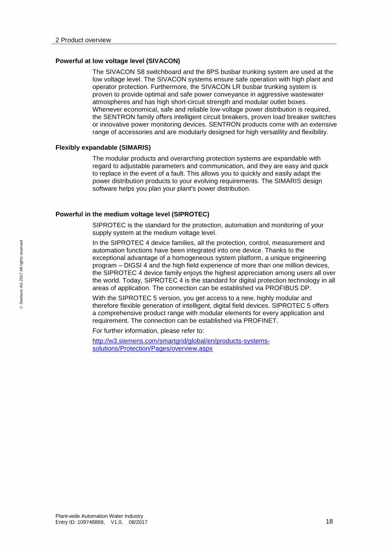
Powerful at low voltage level (SIVACON)
The SIVACON S8 switchboard and the 8PS busbar trunking system are used at the low voltage level. The SIVACON systems ensure safe operation with high plant and operator protection. Furthermore, the SIVACON LR busbar trunking system is proven to provide optimal and safe power conveyance in aggressive wastewater atmospheres and has high short-circuit strength and modular outlet boxes. Whenever economical, safe and reliable low-voltage power distribution is required, the SENTRON family offers intelligent circuit breakers, proven load breaker switches or innovative power monitoring devices. SENTRON products come with an extensive range of accessories and are modularly designed for high versatility and flexibility.
Flexibly expandable (SIMARIS)
The modular products and overarching protection systems are expandable with regard to adjustable parameters and communication, and they are easy and quick to replace in the event of a fault. This allows you to quickly and easily adapt the power distribution products to your evolving requirements. The SIMARIS design software helps you plan your plant's power distribution.
Powerful in the medium voltage level (SIPROTEC)
SIPROTEC is the standard for the protection, automation and monitoring of your supply system at the medium voltage level.
In the SIPROTEC 4 device families, all the protection, control, measurement and automation functions have been integrated into one device. Thanks to the exceptional advantage of a homogeneous system platform, a unique engineering program – DIGSI 4 and the high field experience of more than one million devices, the SIPROTEC 4 device family enjoys the highest appreciation among users all over the world. Today, SIPROTEC 4 is the standard for digital protection technology in all areas of application. The connection can be established via PROFIBUS DP.
With the SIPROTEC 5 version, you get access to a new, highly modular and therefore flexible generation of intelligent, digital field devices. SIPROTEC 5 offers a comprehensive product range with modular elements for every application and requirement. The connection can be established via PROFINET.
For further information, please refer to:
http://w3.siemens.com/smartgrid/global/en/products-systems-solutions/Protection/Pages/overview.aspx

2 Product overview
Plant-wide Automation Water Industry Entry ID: 109748869, V1.0, 08/2017 19
S
iem
en
s A
G 2
01
7 A
ll ri
gh
ts r
ese
rve
d
Powerful energy management (SIMATIC Energy Manger PRO)
Energy is a valuable resource. If you want to cut energy costs, increase your competitiveness and meet statutory requirements, you already know how important it is to have integrated energy management in the process. To be able to make the right decisions at the right time, you must always keep an eye on the energy consumption of your entire company. For this purpose, Siemens has created SIMATIC Energy Management – a comprehensive and scalable product and solution portfolio certified by ISO-50001, which can collect energy data at the field level and even provide company-wide energy analyses at the management level.
Your advantages with SIMATIC Energy Manager PRO (SQL) / B.Data (Oracle):
As an operator
– Make energy consumption visible – Energy data linked to process data
– Cut down on energy costs – identify high energy consumers and optimize energy acquisition
– Fulfil legal requirements efficiently –
through ISO-50001 conformity and TÜV certification
– Scalability –
from the sub process to the energy management across all plants
As a planner
– Integrated solution – through project planning via SIMATIC Energy Suite (TIA Portal)
– Efficient configuration – through customized metrics and flexible web dashboards
– Open and secure system – thanks to numerous interfaces and safe communication
– Scalability – from the sub process to the energy management across all plants
2 Product overview
Plant-wide Automation Water Industry Entry ID: 109748869, V1.0, 08/2017 20
S
iem
en
s A
G 2
01
7 A
ll ri
gh
ts r
ese
rve
d
2.6 Panel integration
The SIMATIC SCADA system for process visualization offers a flexible system for monitoring and controlling processes in the water sector. It offers all functions for operator control and monitoring and can be extended at any time with branch-specific options, e.g. for telecontrol or archiving and reporting tasks related to the water industry. Integrated diagnostics units facilitate plant maintenance and ensure fast, successful troubleshooting in the event of a fault.
The panels are configured with TIA Portal. If the panels are designed as an independent solution (e.g. configured as a package-solution close to the machine), you can integrate them with building blocks from the Industry Library (IL).
The following versions are available:
STEP 7 optionally with S7-CFC and IL
SIMATIC PCS 7 with IL. For more detailed information on the integration of Comfort and Operator Panels in SIMATIC PCS 7, refer to:
https://support.industry.siemens.com/cs/ww/en/view/50708061.
For an overview of the SIMATIC HMI portfolio, please visit:
http://w3.siemens.com/mcms/automation/en/human-machine-interface/Pages/Default.aspx
SIMATIC HMI Key Panels
Key panels are compact pushbutton panels and complement the classic touch screen panel operation. PROFINET allows you to integrate the key panels into existing automation networks – without complex cabling and with no additional hardware.
SIMATIC HMI Basic Panel
The HMI Basic Panels are the entry-level series for simple visualization tasks. The HMI devices contain numerous basic functionalities (e.g. alarm logging and trends), are easy to configure and provide intuitive operation.
SIMATIC HMI Comfort Panels
SIMATIC HMI Comfort Panels are designed for implementing high-performance visualization tasks at machine level. High performance, functionality and numerous integrated interfaces offer maximum convenience in high-end applications.
SIMATIC Advanced HMI PC based
The powerful HMI PC based panels are used for data intensive and complex visualization tasks. These consist of a small PC and a panel, and provide maximum performance and flexibility for your application. You can choose between the following variants:
All-in-one PC
Separate in panel and PC

2 Product overview
Plant-wide Automation Water Industry Entry ID: 109748869, V1.0, 08/2017 21
S
iem
en
s A
G 2
01
7 A
ll ri
gh
ts r
ese
rve
d
2.7 Water management system
With the modular water management system SIWA, you can control and manage your plant and infrastructure intelligently. This smart water solution is based on the SIMATIC PCS 7 process control system and contains flexible software modules that can be combined with one another. The software assists you in the following subjects:
Optimization of processes
Detection and localization of leaks
Dynamic simulation of pipeline systems
SIWA Leak / SIWA LeakControl leak detection
SIWA Leak and SIWA LeakControl are both systems that help detect large as well as slow leaks in water transport pipelines and distribution systems. By continuously recording the state of the water pipes, you get vital information that helps you implement the right countermeasures when a leak occurs.
SIWA SEWER network control
SIWA SEWER has been specially developed for operators of sewer networks and sewage treatment plants. The system controls the ductwork and helps regulate sewage flows and storage volumes in the network. As a result, sewage treatment plants are utilized more consistently, energy costs are reduced, the risk of damage to the pipe system is minimized, and the discharge of untreated sewage into natural waters is prevented.
SIWA CONCEPT / SIWA OTS simulation and training
SIWA CONCEPT builds a computer-aided model of network infrastructure to simulate hydraulic behavior in water supply systems. The simulation allows different operating methods and complex interdependencies of the network to be viewed and investigated in a virtual environment.
SIWA OTS has been specially designed as an educational and training tool for personnel. Thanks to the simulation, operators can be taught the basic system functions, and trained on how to handle the control system and how to deal with extraordinary events in a realistic manner.
SIWA Secure Homeland Security
Besides hydraulic parameters, SIWA Secure also calculates various chemical concentrations in the network and, in an emergency, it enables reliable assessment of the water quality in all network areas. SIWA Secure records pollutant entries and helps the operator implement appropriate countermeasures with the aim of limiting the harmful effects to the smallest possible section of a network.
2 Product overview
Plant-wide Automation Water Industry Entry ID: 109748869, V1.0, 08/2017 22
S
iem
en
s A
G 2
01
7 A
ll ri
gh
ts r
ese
rve
d
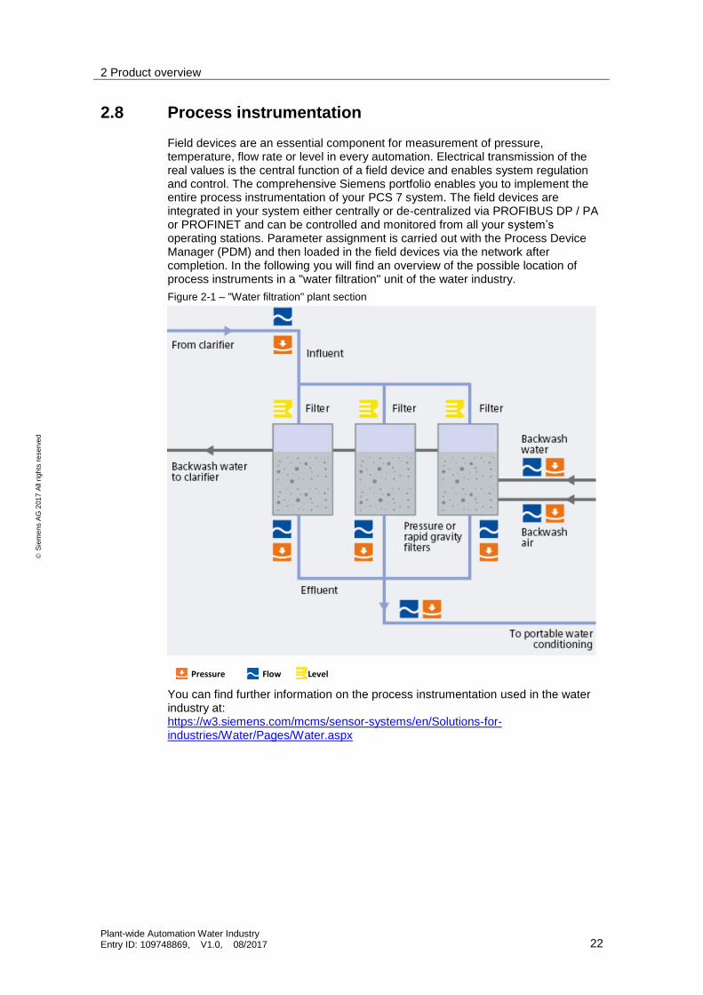
2.8 Process instrumentation
Field devices are an essential component for measurement of pressure, temperature, flow rate or level in every automation. Electrical transmission of the real values is the central function of a field device and enables system regulation and control. The comprehensive Siemens portfolio enables you to implement the entire process instrumentation of your PCS 7 system. The field devices are integrated in your system either centrally or de-centralized via PROFIBUS DP / PA or PROFINET and can be controlled and monitored from all your system’s operating stations. Parameter assignment is carried out with the Process Device Manager (PDM) and then loaded in the field devices via the network after completion. In the following you will find an overview of the possible location of process instruments in a "water filtration" unit of the water industry.
Figure 2-1 – "Water filtration" plant section
Pressure Flow Level
You can find further information on the process instrumentation used in the water industry at: https://w3.siemens.com/mcms/sensor-systems/en/Solutions-for-industries/Water/Pages/Water.aspx

3 Specific solutions / approaches
Plant-wide Automation Water Industry Entry ID: 109748869, V1.0, 08/2017 23
S
iem
en
s A
G 2
01
7 A
ll ri
gh
ts r
ese
rve
d
3 Specific solutions / approaches The standardization of automation engineering for process plants, such as in the water industry, is a major challenge. Different process actions and procedures, different devices and flexibility in the process make this task even more difficult.
One standardization approach includes the use of standard libraries and the configuring of the plant according to the physical model of the DIN EN 61512 standard. This specifies the lower four levels, i.e. plant, unit, equipment module and control module. A plant always consists of units. The unit can in turn contain standardized equipment modules, also known as technical functions.
3.1 PCS 7 libraries
The SIMATIC PCS 7 Advanced Process Library (APL) and Industry Library (IL) are available for implementation. Through the libraries, you can design your automation in a standardized way by means of predefined blocks.
Advanced Process Library
The library building blocks of APL cover a wide range of functions for process automation, such as channel blocks, controller blocks, technology blocks and maintenance blocks. When you create the automation program, the associated data blocks are installed automatically. Uniform operating elements (faceplates) are also created automatically for the visualization process.
User-friendly engineering with the APL library reduces the effort involved in creating your standardized system.
You can find further information about the Advanced Process Library at:
http://w3.siemens.com/mcms/process-control-systems/en/distributed-control-system-simatic-pcs-7/simatic-pcs-7-system-components/System_Libraries/Pages/Advanced-Process-Library.aspx
SIMATIC PCS 7 Advanced Process Graphics
Increasingly complex process plants pose an enormous challenge to operating personnel. For this reason, it is important for relevant process information to be available and for plant conditions and operational parameters to be displayed in the control room in a clear, simple and well-arranged manner. Only in this way can the correct decisions be made and the appropriate measures taken quickly. For effective process control, APG offer hybrid views, trend curves, and Kiviat charts that provide information instead of data to operators.
Condition Monitoring Library
The SIMATIC PCS 7 Condition Monitoring Library (CML) provides blocks for economic monitoring and analysis of mechanical assets (plant components such as pumps, valves, etc.) that increase efficiency and availability and detect possible damages as early as possible.
The CML blocks in APL style fit perfectly into the process pictures based on APL.
The following blocks are available:
PumpMon for monitoring electrically driven rotary pumps with constant and variable speed (e.g. cavitation monitoring)
VlvMon for monitoring continuously variable valves with position feedback (e.g. mechanical damage and soot build-up)
3 Specific solutions / approaches
Plant-wide Automation Water Industry Entry ID: 109748869, V1.0, 08/2017 24
S
iem
en
s A
G 2
01
7 A
ll ri
gh
ts r
ese
rve
d
Industry Library
The Industry Library extends the functional scope of the standard APL functionality with the same look and feel. Thus the libraries complement each other perfectly and offer a uniform overall solution. The Industry Library supplies blocks for the following applications:
Extended multiple control room concept
HVAC
Small load management
Extended unit control
Special process data monitoring (8 limits)
Connection of S7-300 to PCS 7
You can find further information on the Industry Library at:
http://w3.siemens.com/mcms/process-control-systems/en/distributed-control-system-simatic-pcs-7/simatic-pcs-7-technologies/technology_libraries/Pages/Industry-Library.aspx
SITRANS library
By means of the SITRANS Library, you can integrate process instruments of the product families SITRANS and SIPART into the SIMATIC PCS 7 process control system with high quality, efficiency and safety. You can also integrate them in the S7-300 and S7-400controllers and in a WinCC system for operation and monitoring as well as in SIMATIC comfort panels with TIA Portal. The look and feel is based on the APL standard of SIMATIC PCS 7 and is thus uniform for all target systems.
You can find further information on the supported system versions at: siemens.com/support/sitranslibrary
SIMATIC PowerControl
SIMATIC PCS 7 PowerControl allows the integration of switchboards in the SIMATIC PCS 7 process control system. This enables the merging of process automation and the automation of electrical switchboards for medium voltages in one control system. The advantage for plant operators: significant cost savings over the entire life cycle of the plant.
For further information on PowerControl, please refer to:
http://w3.siemens.com/mcms/process-control-systems/en/distributed-control-system-simatic-pcs-7/simatic-pcs-7-technologies/PowerControl/Pages/SIMATIC-Power-Control.aspx

3 Specific solutions / approaches
Plant-wide Automation Water Industry Entry ID: 109748869, V1.0, 08/2017 25
S
iem
en
s A
G 2
01
7 A
ll ri
gh
ts r
ese
rve
d
3.2 Application examples
Application examples support you with functional solutions. Instead of emphasizing on just the single product, they rather deal with the interaction of the entire system. You can use the following application examples to develop know-how and as a template for your plant section in the water industry:
Typical Configurations in Water and Sewage Technology
https://support.industry.siemens.com/cs/ww/en/view/61024766
Remote Configurations in Water and Wastewater Technology
https://support.industry.siemens.com/cs/ww/en/view/61024137
Example project: Remote control of S7-1200 RTU with PCS 7 TeleControl (IEC protocol)
https://support.industry.siemens.com/cs/ww/en/view/109475749
Standard PCS 7 and S7 Water Templates for the water industry
https://support.industry.siemens.com/cs/ww/en/view/78604785
3.3 Water-specific master data library and templates
For standardized automation, Siemens offers a special library and configuration templates tailored to the requirements of the water industry. This is based on the Industry Library, which is available as an add-on product for SIMATIC PCS 7 V8.0 and WinCC V7. or higher. The PCS 7 and S7 templates that are based on this enable a standardized implementation of complete package solutions as well as smaller operation and functional units. The templates are already preconfigured and contain all the typical components for controllers and closed loop controls. The implementation is carried out with SIMATIC PCS 7, SIMATIC WinCC or WinCC Professional (TIA Portal).
Water Templates
The Water Templates consist of three hierarchically successive groups and are based on the physical model of the NAMUR NE33 and ISA S88.01 (ANSI / ISA-88.01-1995) standards.
Figure 3-1: Siemens Water Templates in relation to NAMUR / ISA
3 Specific solutions / approaches
Plant-wide Automation Water Industry Entry ID: 109748869, V1.0, 08/2017 26
S
iem
en
s A
G 2
01
7 A
ll ri
gh
ts r
ese
rve
d
Performance of the Water Templates
PCS 7 Water Templates offer you a solution approach in the following areas:
Simple multi-user control 1 out of 8 control locations
Integrated Panel operation (optional mosaic Panel connection)
Integrated local controls (HW) without automation (AS)
Integrated local controls (SW) with automation
Unit switchover for 8 / 16 drives
96 turning points with 15 minutes setpoint curve specifications
Programmable and controllable polygon with 8 turning points
Monitoring of measured values with up to 8 limit values
Time-driven controller for simple process operations
Simple Integration of package unit solutions with S7-300 in the automation solution
Provision of additional monitoring functions of centrifugal pumps and control valves
Complete drive solutions (pumps, agitators, etc.) via field bus connection with SIMOCODE pro V (incl. HW engineering)
Complete drive solutions (dosing pumps, blowers, etc.) via field bus connection with SINAMICS G120
Integrated solution with process instrumentation via field bus connection with SITRANS MAG 6000
Licensing concept
To use the PCS 7 / S7 Water Templates you must have the following licensed components installed:
SIMATIC PCS 7 Add-on Industry Library (IL)
SITRANS Library (SL)
SIMOCODE ED and / or STARTER license
3.3.1 Standards and guidelines
The water templates comply with the requirements of the IEC 62424 and ATV M260 standards and are based on DIN / VDI / VDE / IEC / ISO standards.
Standard / guideline Description
ATV-DVWK-M260 Capture, display, evaluate and archive the automated operation of sewage plants
DWA-M 253 Process control and automation of sewage plants
DWA-M 207 Information and communication networks for sewage plants
DWA- M181 Fill level and flow measurement in drainage systems
ISO 7000, IEC 60417 Graphical symbols for the operating resources used
IEC 62424 Technical representation of the process control using P&I diagrams and data exchange between P&ID tools and PCE-CAE tools
DIN 2403 Labeling of the pipe flow medium
3 Specific solutions / approaches
Plant-wide Automation Water Industry Entry ID: 109748869, V1.0, 08/2017 27
S
iem
en
s A
G 2
01
7 A
ll ri
gh
ts r
ese
rve
d
3.3.2 Water Control Module Types (WCMT) / Water Process Tag Types (WPTT)
The smallest functional unit of the templates consists of the Water Process Tag Types (WPTT) and Water Control Module Types (WCMT). These are used for closed loop controls, measuring value detection, actuator control, etc. WCMTs are enhanced WPTTs and offer the following advantages for engineering in SIMATIC PCS 7 and for mass data engineering with COMOS or with the PCS 7 Advanced Engineering System:
Instance-specific changes to the instance of the control module are not lost during synchronization between type and instance.
It is possible to generate different variants for an instance based on a single control unit type. In addition to this, optional blocks are also configured in WCMT. The activated optional blocks are predefined for each instance. As of PCS 7 V8.0, this is done in the additional "Technological Connections" view of the CFC.
You can find the "Standard PCS 7 and S7 Water Templates for the water industry" at:
https://support.industry.siemens.com/cs/ww/en/view/78604785
3.3.3 Water Equipment Module Templates (WEMT)
Water Equipment Modules Templates (WEMT) are available for technical units which can be composed of controls, valves, sensors, devices / actuators and / or mechanical components. The individual WEMTs are grouped from various PCS 7 Water Templates (WCMT) or consist of separate control system operation units.
The WEMTs for control system operations (e.g. multi-user selection, aggregate switching, package unit connection) are stored as CFCs. Controls, such as the split range control, are created in the form of a sample solution. WEMTs store data in a PCS 7 master data library, consisting of:
a CFC
a PCS 7 OS block icon
PCS 7 APL faceplates.
Processing via mass data engineering using COMOS /
An overview of the available WEMTs can be found in the article:
You can find the "Standard PCS 7 and S7 Water Templates for the water industry" at:
https://support.industry.siemens.com/cs/ww/en/view/78604785
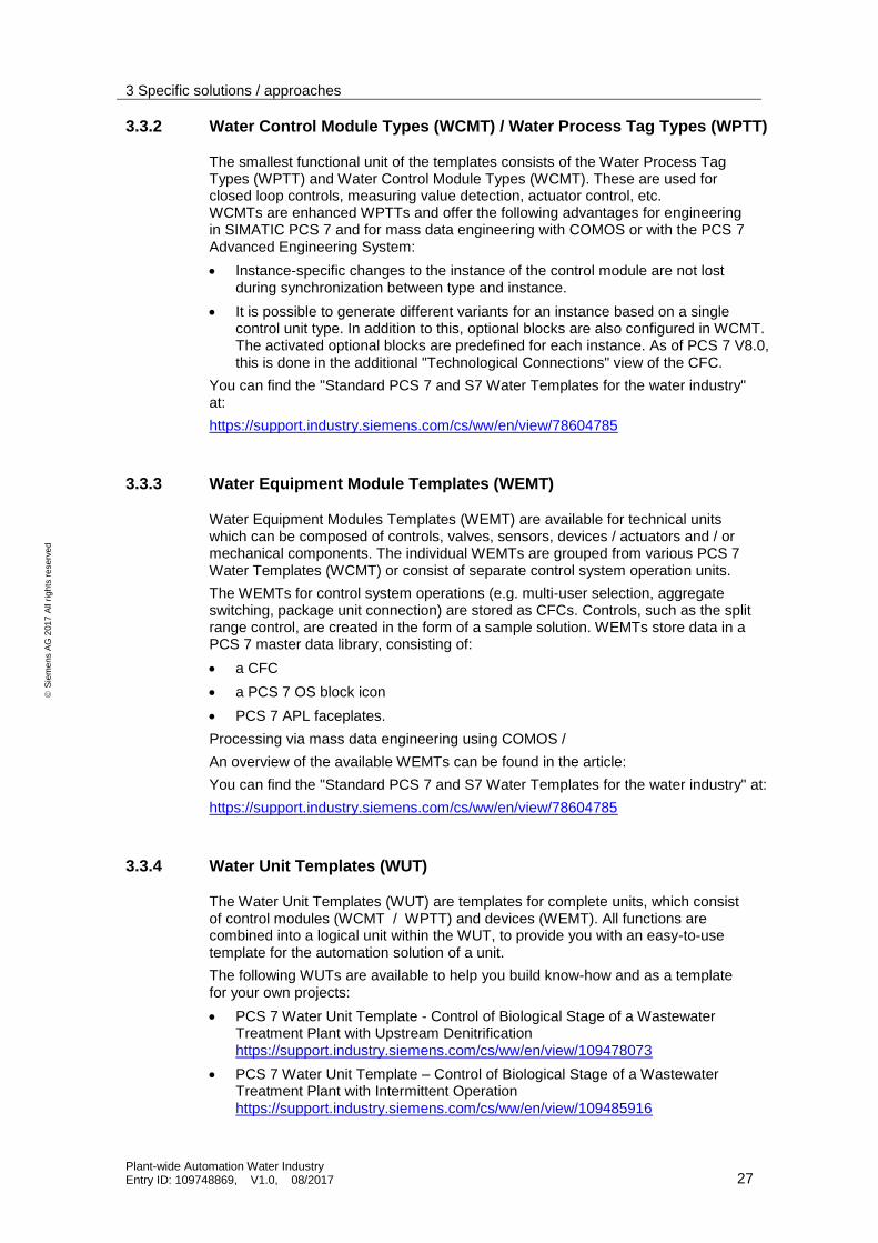
3.3.4 Water Unit Templates (WUT)
The Water Unit Templates (WUT) are templates for complete units, which consist of control modules (WCMT / WPTT) and devices (WEMT). All functions are combined into a logical unit within the WUT, to provide you with an easy-to-use template for the automation solution of a unit.
The following WUTs are available to help you build know-how and as a template for your own projects:
PCS 7 Water Unit Template - Control of Biological Stage of a Wastewater Treatment Plant with Upstream Denitrification https://support.industry.siemens.com/cs/ww/en/view/109478073
PCS 7 Water Unit Template – Control of Biological Stage of a Wastewater Treatment Plant with Intermittent Operation https://support.industry.siemens.com/cs/ww/en/view/109485916

3 Specific solutions / approaches
Plant-wide Automation Water Industry Entry ID: 109748869, V1.0, 08/2017 28
S
iem
en
s A
G 2
01
7 A
ll ri
gh
ts r
ese
rve
d
PCS 7 Water Unit Template – Efficient Management of Storm Water Tank https://support.industry.siemens.com/cs/ww/en/view/109481487
PCS 7 Water Unit Template – External Pump Station of a Wastewater Treatment Plant (WWTP) https://support.industry.siemens.com/cs/ww/en/view/109481486
3.3.5 Control strategy of the water-specific templates
The control strategy in the water industry is usually based on multi-user control, which allows access to a maximum of eight different locations (e.g. OS servers or panels). The control strategy has four different levels of control rights, which are also defined by prioritization. This definition of the control strategy is implemented uniformly by the templates.
Operation mode description Operation priority
Possible actions
Central remote control room(s):
The operator controls one or several water stations from a central control room by means of the SIMATIC OS user interface.
1 (lowest) Manual operation
Automatic operation
Remote operation of every actuator
Local control room:
The operator controls one or several water stations from a local control room by means of the SIMATIC OS user interface.
2 Manual operation
Automatic operation
Remote operation of every actuator
Local panel:
Local operation of functions via panels directly on the control cabinet. The operator controls a local sub-section of the plant via the panels.
3 Manual operation
Automatic operation
Local panel operation
Local devices:
Local operation gets the highest priority and is divided into three different operating concepts.
4 (highest) Operation with panels connected to the automation system
Operation with local software switches connected to the automation system
Operation with local hardware switches, connected directly to the local electro-technical devices and / or in the control cabinet. During normal operation with communication to the Process Control System, only signal tracking is performed. In the event of a complete failure of the control and / or automation system, local operation and monitoring are ensured at all times in emergency mode.
The local hardware interconnection of functions has priority over local software interconnection if local operation takes place via both paths at the same time. The

3 Specific solutions / approaches
Plant-wide Automation Water Industry Entry ID: 109748869, V1.0, 08/2017 29
S
iem
en
s A
G 2
01
7 A
ll ri
gh
ts r
ese
rve
d
following figure illustrates the operation via local software and hardware switches. Both variants can be operated via direct interconnection and an automation system.
Figure 3-2: Operation via local software switch or hardware switch
Note Further information about the multi-user concept can be found in the manual of the PCS 7 Industry Library at: https://support.industry.siemens.com/cs/ww/en/view/109738716

4 Guidelines for planning and configuring
Plant-wide Automation Water Industry Entry ID: 109748869, V1.0, 08/2017 30
S
iem
en
s A
G 2
01
7 A
ll ri
gh
ts r
ese
rve
d
4 Guidelines for planning and configuring There are binding requirements for the implementation of automation projects in the water industry. These are listed in the IEC 62424 and ATV M260 directives (only for wastewater management). To a certain extent, the requirements mentioned here apply as a general rule to a standardization and especially to the application of the Siemens Water Templates.
You can find further information on the IEC directives that apply to the water industry at: http://www.iec.ch/about/brochures/pdf/about_iec/IEC_role_in_water_management.pdf
4.1 Engineering
The standardization of the automation solution is based on the general requirements for engineering to ensure a uniform procedure when creating a solution and / or applying the PCS 7 templates.
PCS 7 compendia
Create your own PCS 7-compliant and upgradable solutions according to the following PCS 7 recommendations:
PCS 7 Compendium Part A - Configuration Guidelines
PCS 7 Compendium Part B - Process Safety
PCS 7 Compendium Part C - Technical Functions with SFC Types
PCS 7 Compendium Part D - Operation and Maintenance
PCS 7 Compendium Part E - Hardware Configuration
PCS 7 Compendium Part F - Industrial Security
You can find an overview of the PCS 7 compendia at the following link:
http://www.siemens.com/industry/onlinesupport/pcs7
PCS 7 libraries
To implement and create your own solutions, use the following PCS 7 libraries:
PCS 7 Advanced Process Library (APL) https://support.industry.siemens.com/cs/ww/en/view/109739941
SIMATIC PCS 7 Industry Library (IL) https://support.industry.siemens.com/cs/ww/en/view/109738715
SITRANS Library for PCS 7 (SL) https://support.industry.siemens.com/cs/ww/en/view/109737969
PCS 7 Advanced Process Graphics (APG) https://support.industry.siemens.com/cs/ww/en/view/109747809
PCS 7 Condition Monitoring Library https://support.industry.siemens.com/cs/ww/en/view/109738723
Note If you intend on using the Industry Library and the SITRANS Library in your configuration environment or in process mode, you are obliged to buy the engineering and runtime licenses.

4 Guidelines for planning and configuring
Plant-wide Automation Water Industry Entry ID: 109748869, V1.0, 08/2017 31
S
iem
en
s A
G 2
01
7 A
ll ri
gh
ts r
ese
rve
d
Standardized engineering
By using the water templates (WEMT / WPTT / WCMT) resolutely, you achieve consistent standardization of your unit or entire plant. This forms the basis for future migrations.
Alarm limits and messages
For all analog measurements in your own solution, use the templates WCMT_MonAnalog08 and WCMT_S/MonAnalog08. The following table gives you the definitions of the alarm messages:
Limit P&ID diagram Description
L1 AHH Alarm High-High
L2 AH Alarm High
L3 WH (SHH) Warning High; can also be used as SHH, Switch High-High
L4 SH Switch High
L5 SL Switch Low
L6 WL (SLL) Warning Low; can also be used as SLL, Switch Low-Low
L7 AL Alarm Low
L8 ALL Alarm Low-Low
Archiving and reporting
For long-term archiving and reporting according to ATV-DVWK-M260, it is recommended to use the following solutions that create conformant archiving:
ACRON add-on (by Videc)
Energy Manager Pro / B. Data (by Siemens)
Creating CFCs
For a uniform program structure and standardization of the software when creating your own CFCs use the standard functions and function blocks of the PCS 7 Advanced Process Library, Industry Library and SITRANS Library.
SI unit
Assign the corresponding physical units (SI units) for your measured values. The APL supports you with a large variety of SI units, which are configured in the display module and channel blocks during the engineering phase.
Note From PCS 7 V9.0, you can apply up to 199 customized units.
Multiproject / Multiuser engineering
SIMATIC PCS 7 helps you configure automation projects effectively. In multiproject engineering, full automation tasks are generally divided into several PCS 7 projects. Each of these is then processed separately on distributed engineering stations by one project engineer and subsequently synchronized with the central engineering server.
On the other hand, in the case of multiuser engineering, several users work on the same project via network.
4 Guidelines for planning and configuring
Plant-wide Automation Water Industry Entry ID: 109748869, V1.0, 08/2017 32
S
iem
en
s A
G 2
01
7 A
ll ri
gh
ts r
ese
rve
d
In the following application example, the engineering procedures are described in a practical way and in some cases with step by step instructions: https://support.industry.siemens.com/cs/ww/en/view/22258951
Creating new functions / function blocks
When creating your own functions (FC) and function blocks (FB), observe the following prerequisites:
Implementation with SIMATIC SCL
It is not permitted to use S7 timers, S7 counters and S7 flags
Tags are handled within the instance-specific data block (DB)
Function blocks run in each runtime OB
The block must fulfill the following functions
– Restart (set / reset parameters to the default values depending on their function)
– New instance of the block (to facilitate the on-line instantiation of the block)
– Changing the sampling rate

4 Guidelines for planning and configuring
Plant-wide Automation Water Industry Entry ID: 109748869, V1.0, 08/2017 33
S
iem
en
s A
G 2
01
7 A
ll ri
gh
ts r
ese
rve
d
4.2 Naming convention
The naming conventions with your own classification make your project easier to read. The naming convention applies to the ATV-DVWK-M260 guideline and was applied in the Water Templates.
Note Standardization also means that all measuring points in your projects must have resolute and consistent labeling according to the industry-specific naming convention.
Naming convention of the Water Templates
The WCMT, WPTT and WEMT Water Templates have uniform names and term definitions for quick assignment of tasks and functions. They are made up of the following three criteria:
1. Template type (WCMT, WPTT, WEMT)
2. Template function (Name = technology block name from the APL, IL or SITRANS Library)
3. Signal connection (without text /_Fb /_FbMMS /_FbDrv)
Example: WCMT_MonAnalog_Fb
For further information about the naming convention of the templates, see: Standard PCS 7 and S7 Water Templates for the water industry
https://support.industry.siemens.com/cs/ww/en/view/78604785
Note The naming convention of the Water Templates concerns the naming of the template. The labeling of the measuring point follows the general naming convention.

4 Guidelines for planning and configuring
Plant-wide Automation Water Industry Entry ID: 109748869, V1.0, 08/2017 34
S
iem
en
s A
G 2
01
7 A
ll ri
gh
ts r
ese
rve
d
General naming convention of the measuring points
For the names of the individual measuring points, use the following convention:
XXN_XXXX_XX
Process action
Measuring principle
Element
The label of the process action must be abbreviated by two characters in accordance with the ATV260 guideline. You can find further relevant information in the list below. The "N" character is optional, in case several actions of the same name are present. The abbreviations for the process actions are shown in the table below.
Measuring principle, such as FQIR, LIS
Element: two characters with leading zero
Process action abbreviation
Process action
ATV 260 DVD
RB RB Rain overflow basin
P PW External pump station (medium size)
PW ZL Pump station inlet
FA AM External measuring station
AS AS Wastewater receiving station
RE RE Screen
SF SF Gravel / grease separator
VK VK Primary sedimentation basin
FL KN Precipitating agent dosing
MB / DN / NI AN / DN / NI Aeration basin (anaerobic, denitrification, nitrification)
GS TV Turbo compressor / fan for aeration basin
NK NK Secondary sedimentation basin
RS / US RL / NI Sludge return and discharge pumping station
AU ??? Runout
FK PF Flocculation monitoring for drainage
SE UE Sludge runoff drying
FA / AY FB Digester and gas analysis
GB / GF GB Gas reservoir and gas flame
NA / BK NE Backup energy system
VE / NE VE Sludge thickening and sludge treatment
KP FS / FP Sludge dewatering
NS / MS Energy system (small and medium)
BG Air conditioning and general systems (e.g. exterior lighting, alarm system, entry control)
BW --- Tap water
HW HW High water pump station

4 Guidelines for planning and configuring
Plant-wide Automation Water Industry Entry ID: 109748869, V1.0, 08/2017 35
S
iem
en
s A
G 2
01
7 A
ll ri
gh
ts r
ese
rve
d
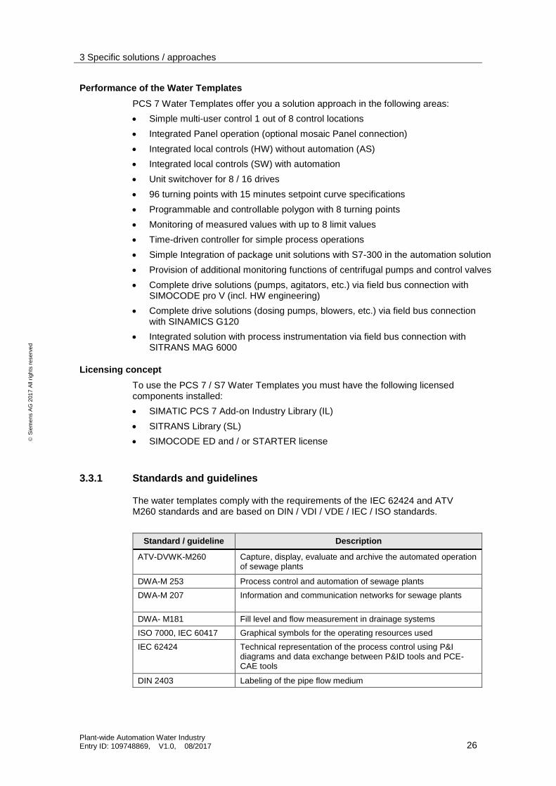
4.3 P&ID diagram
A P&ID diagram maps the modes of action of the individual process variables and components in a plant or unit. This representation helps when configuring the automation system and when creating OS user interfaces.
In the following section, you will find examples for P&ID diagrams of various motor and valve versions as a simplified representation.
Template N1 - Symbol for motor with simple speed
Templates N2 – Symbol for motor with simple speed and control via SIMOCODE pro V
Mxxx-nn
NS
xxx-nn.1H
OSH
OSLLocal HW
xxx-nn.2H
OSH
OSLLocal SW
xxx-nn.3H
SH
Local SW – Fwd /
Local SW – Speed 1
xxx-nn.5H
SLLocal SW - Stop
xxx-nn.6H
OSH
OSLMaintenance
xxx-nn.7N
OSLTripCF
xxx-nn.8N
OSLTripMMS
xxx-nn.13EIR
Current
AH
SL
SL
xxx-nn.4H
SH
Local SW – Rev /
Local SW – Speed 2 (1)
(1) Not used for motor with one direction
(1) Not used for motors with one speed
xxx-nn.9N
OSH
Fbk – Fwd /
Fbk – Speed 1
xxx-nn.10N
OSH
Fbk – Rev /
Fbk – Speed 2
SH
SH
(1)
xxx-nn.11N
SH
SLRun – Fwd /
Run – Speed 1
N1
xxx-nn.12N
SH
SLRun – Rev /
Run – Speed 2(1)
Mxxx-nn
NS
xxx-nn.2H
OSH
OSLLocal SW
xxx-nn.3H
SH
Local SW – Fwd /
Local SW – Speed 1
xxx-nn.13EIR
Current
AHxxx-nn.4
HSH
Local SW – Rev /
Local SW – Speed 2 (1)
(1) Not used for motor with one direction
(1) Not used for motors with one speedxxx-nn.5
H
SLLocal SW - Stop
N2

4 Guidelines for planning and configuring
Plant-wide Automation Water Industry Entry ID: 109748869, V1.0, 08/2017 36
S
iem
en
s A
G 2
01
7 A
ll ri
gh
ts r
ese
rve
d
Templates N3 - Symbol for motor with variable speed
Template N4 - Symbol for motor with variable speed and control via SINAMICS G120)
xxx-nn.14SI
Speed
AH
AL
Mxxx-nnNIC
xxx-nn.1H
OSH
OSLLocal HW
xxx-nn.2H
OSH
OSLLocal SW
xxx-nn.3H
SH
xxx-nn.5H
SLLocal SW - Stop
xxx-nn.6H
OSH
OSLMaintenance
xxx-nn.7N
OSLTripCF
xxx-nn.8N
OSLTripMMS
xxx-nn.13EIR
Current
AH
OSL
OSL
xxx-nn.4H
SH
(1)
(1) Not used for motor with one direction
xxx-nn.9N
OSH
Fbk – Fwd
xxx-nn.10N
OSH
Fbk – Rev
OSH
OSH
(1)
xxx-nn.11N
SH
SLRun – Fwd /
Run – Speed 1
N3
xxx-nn.12N
SH
SLRun – Rev /
Run – Speed 2(1)
Mxxx-nnNIC
xxx-nn.2H
OSH
OSLLocal SW
xxx-nn.3H
SH
Local SW - Fwd
xxx-nn.5H
SLLocal SW - Stop
xxx-nn.4H
SH
Local SW - Revxxx-nn.13
EIR
Current
AH
xxx-nn.14SI
Speed
AH
AL
N4
xxx-nn.1H
OSH
OSLLocal HW
xxx-nn.6H
OSH
OSLMaintenance
(1) Not used for motor with one direction
(1)

4 Guidelines for planning and configuring
Plant-wide Automation Water Industry Entry ID: 109748869, V1.0, 08/2017 37
S
iem
en
s A
G 2
01
7 A
ll ri
gh
ts r
ese
rve
d
Template Y1 – On / Off valve
Template Y2 - Symbol for On / Off valve and control via SIMOCODE pro V
Detail view:
Mxxx-nn
YS
xxx-nn.1H
OSH
OSLLocal HW
xxx-nn.2H
OSH
OSLLocal SW
xxx-nn.3H
SH
Local SW – Open
xxx-nn.5H
SLLocal SW - Stop
xxx-nn.6H
OSH
OSLMaintenance
xxx-nn.7Y
OSLTripCF
xxx-nn.8Y
OSLTripMMS
xxx-nn.13EIR
Current
AH
SL
SL
xxx-nn.4H
SH
Local SW – Closexxx-nn.9
YOSH
Fbk – Open
xxx-nn.10Y
OSH
Fbk - Close
SH
SH
xxx-nn.11Y
SH
SLRun
Y1
Mxxx-nn
YS
Y2
Mxxx-nn
YS
xxx-nn.2H
SH
SLLocal SW
xxx-nn.3H
SH
Local SW – Open
xxx-nn.13EIR
Current
AHxxx-nn.4
HSH
Local SW – Close
Y2

4 Guidelines for planning and configuring
Plant-wide Automation Water Industry Entry ID: 109748869, V1.0, 08/2017 38
S
iem
en
s A
G 2
01
7 A
ll ri
gh
ts r
ese
rve
d
Template Y3 - Symbol for analog valve
Template Y4 - Symbol for analog valve and control via SIMOCODE pro V
xxx-nn.14GI
Position
Mxxx-nn
YIC
xxx-nn.1H
OSH
OSLLocal HW
xxx-nn.2H
OSH
OSLLocal SW
xxx-nn.3H
SH
xxx-nn.6H
OSH
OSLMaintenance
xxx-nn.7Y
OSLTripCF
xxx-nn.8Y
OSLTripMMS
xxx-nn.13EIR
Current
AH
SL
SL
xxx-nn.4H
SH
xxx-nn.9Y
OSH
Fbk – Open
xxx-nn.10Y
OSH
Fbk - Close
SH
SH
Y3
xxx-nn.14GI
Position
Mxxx-nn
YIC
xxx-nn.2H
OSH
OSLLocal SW
xxx-nn.3H
SH
xxx-nn.13EIR
Current
AH
xxx-nn.4H
SH
Y4
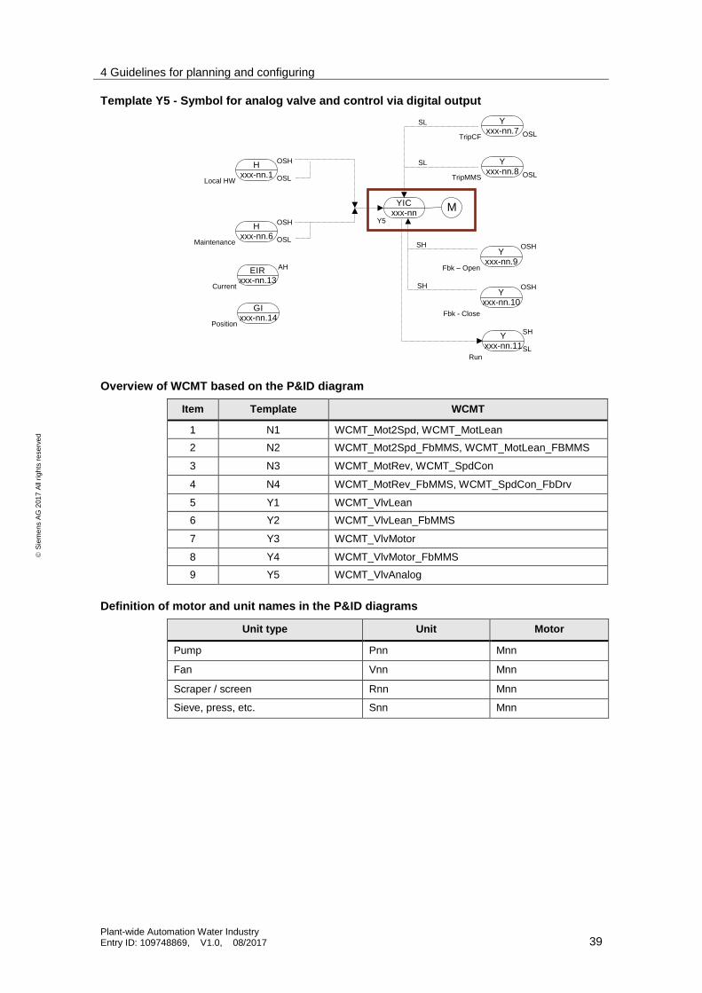
4 Guidelines for planning and configuring
Plant-wide Automation Water Industry Entry ID: 109748869, V1.0, 08/2017 39
S
iem
en
s A
G 2
01
7 A
ll ri
gh
ts r
ese
rve
d
Template Y5 - Symbol for analog valve and control via digital output
Overview of WCMT based on the P&ID diagram
Item Template WCMT
1 N1 WCMT_Mot2Spd, WCMT_MotLean
2 N2 WCMT_Mot2Spd_FbMMS, WCMT_MotLean_FBMMS
3 N3 WCMT_MotRev, WCMT_SpdCon
4 N4 WCMT_MotRev_FbMMS, WCMT_SpdCon_FbDrv
5 Y1 WCMT_VlvLean
6 Y2 WCMT_VlvLean_FbMMS
7 Y3 WCMT_VlvMotor
8 Y4 WCMT_VlvMotor_FbMMS
9 Y5 WCMT_VlvAnalog
Definition of motor and unit names in the P&ID diagrams
Unit type Unit Motor
Pump Pnn Mnn
Fan Vnn Mnn
Scraper / screen Rnn Mnn
Sieve, press, etc. Snn Mnn
xxx-nn.14GI
Position
Mxxx-nn
YIC
xxx-nn.1H
OSH
OSLLocal HW
xxx-nn.6H
OSH
OSLMaintenance
xxx-nn.7Y
OSLTripCF
xxx-nn.8Y
OSLTripMMS
xxx-nn.13EIR
Current
AH
SL
SL
xxx-nn.9Y
OSH
Fbk – Open
xxx-nn.10Y
OSH
Fbk - Close
SH
SH
Y5
xxx-nn.11Y
SH
SLRun

4 Guidelines for planning and configuring
Plant-wide Automation Water Industry Entry ID: 109748869, V1.0, 08/2017 40
S
iem
en
s A
G 2
01
7 A
ll ri
gh
ts r
ese
rve
d
4.4 Process control and operation
A clearly structured and unified interface is required for effective and safe process management. The P&ID diagram forms the basis for the division and arrangement of the user interface of the respective unit. The ATV-DVWK M260 guideline must be applied for the design of PCS 7 and WinCC in demand on the norm ATV-DVWK M260.
You can run the process management for the entire plant either with
the SIMATIC PCS 7 process control system operator station or with
the visualization solution such as WinCC or WinCC Professional in the SCADA environment.
You can also
split the process pictures of the units between various OS clients and
create local visualization by means of panels with restricted user rights for each unit.
Note In the Online Support portal, you can find water-specific example projects of units (Water Unit Templates), which include both the automation program and the process pictures for SIMATIC PCS 7 and TIA Portal (Panel Project).
The following link provides you an overview of industry-specific examples and solutions: https://support.industry.siemens.com/cs/products?mfn=ps&pnid=21154&lc=en-WW
Process level of process pictures in the OS runtime
In the engineering phase, a level can be predefined for each object of a process picture. In this way, you can position the individual graphical objects in such way as to avoid interfering objects, such as faceplates and cables during processing.
Layer Object type
1 Layout
2 Static objects
3 ---
4 ---
5 Piping
6 ---
7 ---
8 ---
9 ---
10 Control modules
11 ---
12 ---
13 ---
14 ---

4 Guidelines for planning and configuring
Plant-wide Automation Water Industry Entry ID: 109748869, V1.0, 08/2017 41
S
iem
en
s A
G 2
01
7 A
ll ri
gh
ts r
ese
rve
d
Color of cables and lines in the process pictures
To standardize the process control interface and achieve a consistent material representation, use the following line colors.

4 Guidelines for planning and configuring
Plant-wide Automation Water Industry Entry ID: 109748869, V1.0, 08/2017 42
S
iem
en
s A
G 2
01
7 A
ll ri
gh
ts r
ese
rve
d
Representation of cables and lines
Use the following line types in the process pictures:
Line type Definition
General Arrows point to the target object, e.g. container
Measuring point line Line width: 1 pixel
Line color: black
Work lines Standard representation and removal is possible by means of a button
Direction is indicated by means of an arrow
Line width: 2 pixels
Line color: black
Side line Line end is represented by the WinCC standard arrow
Line width: 2 pixels
Line color: black
Main process line Line width: 5 pixels
Line end is represented by a separate arrow (see Figure 4-1 Examples for main process lines)
Line color: Based on the color of the main medium (see requirement
"Color of cables and lines in process pictures")
Figure 4-1 Examples for main process lines

4 Guidelines for planning and configuring
Plant-wide Automation Water Industry Entry ID: 109748869, V1.0, 08/2017 43
S
iem
en
s A
G 2
01
7 A
ll ri
gh
ts r
ese
rve
d
Static objects and symbols
For process pictures to have a uniform appearance, you have to create your static objects, images and symbols according to the specifications of the PCS 7 APL Style Guide.
For further information, please refer to:
https://support.industry.siemens.com/cs/ww/en/view/59062870
Text formatting
Use the following formatting in your process pictures:
Static texts of objects, such as containers and lines:
– Font: Arial
– Font size: 11 pixels
– Not bold
Text representation of jump labels:
– Font: Arial
– Font size: 11 pixels
– Bold
Opening process pictures
You can create dynamic jumps in lower-level process pictures by clicking on the static text or arrow.
Figure 4-2 - Creating picture jumps
4.5 Communication
In order to ensure control and consistent plant operation, a communication connection must be set up with the central remote control room for each WUT subproject.
The communication connection can be set up using SIMATIC TeleControl. For further information on how to configure the telecontrol, see the following articles:
Remote Configurations in Water and Wastewater Technology
https://support.industry.siemens.com/cs/ww/en/view/61024137
Creating technological functions with TeleControl and OPEN OS for a consistent Process Visualization in PCS 7
https://support.industry.siemens.com/cs/ww/en/view/109478763

5 Appendix
Plant-wide Automation Water Industry Entry ID: 109748869, V1.0, 08/2017 44
S
iem
en
s A
G 2
01
7 A
ll ri
gh
ts r
ese
rve
d
5 Appendix
5.1 Glossary
Term Explanation
AdvES Advanced Engineering System
APL Advanced Process Library The PCS 7 AP Library V8.1 SP1 contains all the blocks and functionalities of the PCS 7 Library V8.1 SP1 and also offers additional functionalities and entirely new blocks. All parameters of the APL blocks are subject to a new naming convention.
CFC Continuous Function Chart An advanced graphic language with function blocks for configuring continuous control systems.
Process tag (control module)
Actuators and sensors are used at the control module level as control modules. In PCS 7, the control module is implemented with software typicals (control module types) such as a valve, motor, or controller. The implementation in the CFC contains all the relevant building blocks, interconnections, and basic parameters. A control module type is produced from the CFC, which is then stored in the PCS 7 master data library. You can create as many instances as you like from this control module type, for instance using the automation interface. There can be major differences between the instances, e.g. you can select options for functions as well as for the process link. Every label of a control module follows a uniform naming convention. This means that the label provides information about the function and the job of the control module.
Equipment module (technical function)
An equipment module forms part of a unit and contains sensors, actuators and the automation system (hardware and software). Equipment modules are designed and configured for use in concrete applications, such as process technology (dosing device, level or temperature control).
Unit (plant section)
U unit template is composed of various equipment modules that form a partial automation solution. In a unit template, it is also possible to display further information, such as economic or process engineering parameters (KPIs) or the operating times of assemblies. A unit template is grouped in a hierarchy folder and you can easily integrate it into existing projects and adapt it.
Faceplate (picture block / operating screen)
A graphic element on the screen of the operator station which represents, for instance, an analogue control instrument, a hardwired pushbutton or a switch and enables the operator to monitor and operate the device.
Function block A control module as defined in IEC 1131-3. See also "Block".
Instance A copy of a function block, which is reused for the control configuration of a similar application.
Communication connection
The hardware and software for the transmission and reception of analogue and digital information via a communication system such as, for instance, a bus.
TIA With Totally Integrated Automation™, Siemens offers a universal range of products and systems for the efficient automation of plants in the water industry – whether in water, wastewater, irrigation or desalination.
TIP Totally Integrated Power™ stands for integrated electrical power distribution systems for infrastructure, buildings and industry.

5 Appendix
Plant-wide Automation Water Industry Entry ID: 109748869, V1.0, 08/2017 45
S
iem
en
s A
G 2
01
7 A
ll ri
gh
ts r
ese
rve
d
5.2 Service and Support
Industry Online Support
Do you have any questions or need assistance?
Siemens Industry Online Support offers round the clock access to our entire service and support know-how and portfolio.
The Industry Online Support is the central address for information about our products, solutions and services.
Product information, manuals, downloads, FAQs, application examples and videos – all information is accessible with just a few mouse clicks at: https://support.industry.siemens.com
Technical Support
The Technical Support of Siemens Industry provides you fast and competent support regarding all technical queries with numerous tailor-made offers – ranging from basic support to individual support contracts. You send queries to Technical Support via Web form: www.siemens.com/industry/supportrequest
Service offer
Our range of services includes, inter alia, the following:
Product trainings
Plant data services
Spare parts services
Repair services
On-site and maintenance services
Retrofitting and modernization services
Service programs and contracts
You can find detailed information on our range of services in the service catalog: https://support.industry.siemens.com/cs/sc
Industry Online Support app
You will receive optimum support wherever you are with the "Siemens Industry Online Support" app. The app is available for Apple iOS, Android and Windows Phone: https://support.industry.siemens.com/cs/ww/en/sc/2067
5.3 Links and Literature
No. Topic
\1\ Siemens Industry Online Support
https://support.industry.siemens.com
\2\ Link to this entry page of this application example https://support.industry.siemens.com/cs/ww/en/view/109748869
\3\ PCS 7 water industry solution overview
https://w3.siemens.com/mcms/water-industry/en/Pages/water-industry.aspx
\4\ Process instrumentation and analytics: Water industry
https://w3.siemens.com/mcms/sensor-systems/en/Solutions-for-

5 Appendix
Plant-wide Automation Water Industry Entry ID: 109748869, V1.0, 08/2017 46
S
iem
en
s A
G 2
01
7 A
ll ri
gh
ts r
ese
rve
d
No. Topic
industries/Water/Pages/Water.aspx
\5\ Information on Siemens automation and control systems
https://w3.siemens.com/mcms/water-industry/en/process-products-systems/Pages/automation-engineering.aspx
\6\ Siemens product catalog:
https://mall.industry.siemens.com/goos/WelcomePage.aspx?language=en®ionUrl=/
\7\ IEC information brochure about the directives that apply to the water industry http://www.iec.ch/about/brochures/pdf/about_iec/IEC_role_in_water_management.pdf
\8\ Standard PCS 7 and S7 Water Templates for the water industry
https://support.industry.siemens.com/cs/ww/en/view/78604785
\9\ Typical Configurations in Water and Sewage Technology
https://support.industry.siemens.com/cs/ww/en/view/61024766
\10\ Remote Configurations in Water and Wastewater Technology https://support.industry.siemens.com/cs/ww/en/view/61024137
\11\ SIMATIC PCS 7 overview page with specific access for the water industry
https://support.industry.siemens.com/cs/ww/en/view/63481413
\12\ WUT: PCS 7 Water Unit Template - Control of Biological Stage of a Wastewater Treatment Plant with Upstream Denitrification
https://support.industry.siemens.com/cs/ww/en/view/109478073
\13\ WUT: PCS 7 Water Unit Template – Control of Biological Stage of a Wastewater Treatment Plant with Intermittent Operation
https://support.industry.siemens.com/cs/ww/en/view/109485916
\14\ WUT: PCS 7 Water Unit Template – Efficient Management of Storm Water Tank
https://support.industry.siemens.com/cs/ww/en/view/109481487
\15\ WUT: PCS 7 Water Unit Template – External Pump Station of a Wastewater Treatment Plant (WWTP)
https://support.industry.siemens.com/cs/ww/en/view/109481486
\16\ Integration of Comfort Panels, Operator Panels and S7-300 Package Units in SIMATIC PCS 7 with PCS 7 Industry Library
https://support.industry.siemens.com/cs/ww/en/view/50708061
\17\ SIMATIC HMI overview
http://w3.siemens.com/mcms/automation/en/human-machine-interface/Pages/Default.aspx
\18\ What are the system requirements for using SIMATIC PCS 7 Industry Library?
https://support.industry.siemens.com/cs/ww/en/view/73133562
\19\ SIMATIC PCS 7 Industry Library for PCS 7
https://support.industry.siemens.com/cs/de/en/view/81179761
\20\ PCS 7 Libraries APL Style Guide
https://support.industry.siemens.com/cs/ww/en/view/59062870
\21\ Creating technological functions with TeleControl and OPEN OS for a consistent Process Visualization in PCS 7
https://support.industry.siemens.com/cs/ww/en/view/109478763
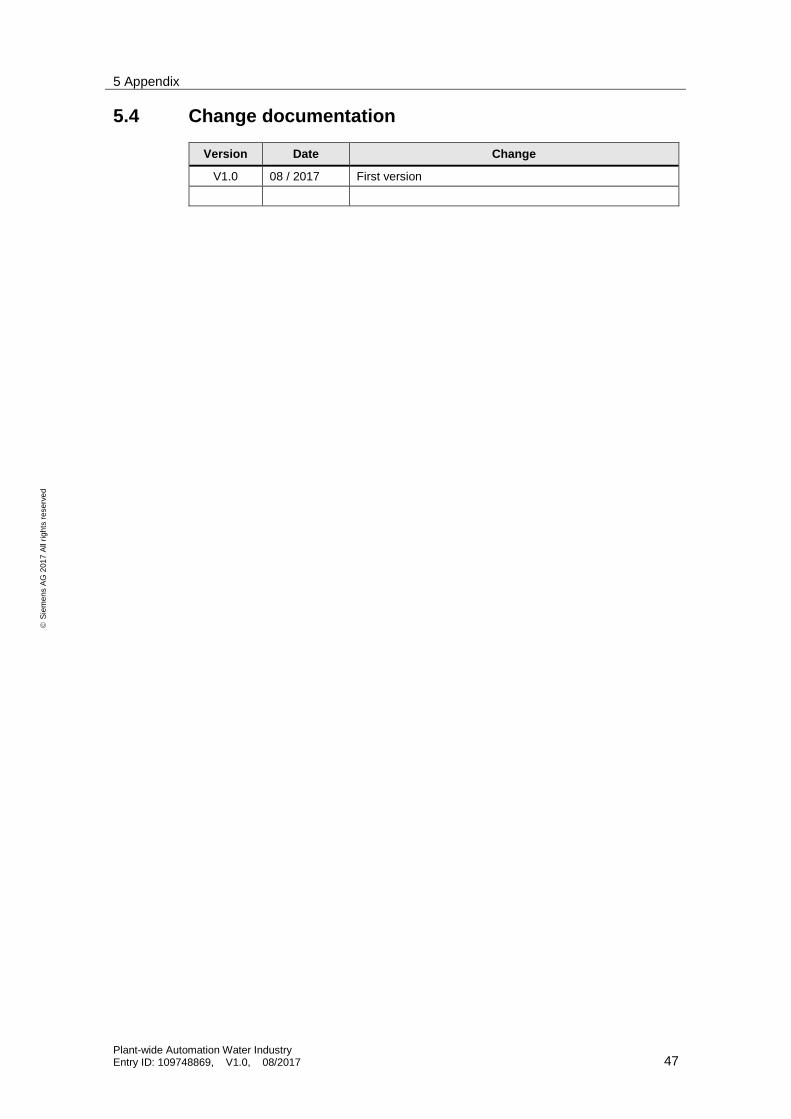
5 Appendix
Plant-wide Automation Water Industry Entry ID: 109748869, V1.0, 08/2017 47
S
iem
en
s A
G 2
01
7 A
ll ri
gh
ts r
ese
rve
d
5.4 Change documentation
Version Date Change
V1.0 08 / 2017 First version