Embed Size (px)
Citation preview

C o m p r e s s i o n s y s t e m s
Plant Air Centrifugal CompressorsTurbo Air® series featuring oil-free air

you have many distinct advantages when you partner with
Cameron's Compression systems for your centrifugal com-
pressor needs. Cameron's Compression Systems manufactures
centrifugal air and gas compressors and provides aftermarket products and services
for a broad customer base around the world. The cutting edge solutions we deliver
for plant air requirements are made possible by the unique blend of product qual-
ity, engineering talent and dedicated teamwork we bring to every customer.
With our main manufacturing facility in Buffalo, NY, USA, located near
Niagara Falls, and distribution in more than 80 sales and service locations worldwide,
Cameron's Compression Systems is a global company with
a singular commitment – meeting your needs with superior
centrifugal compressor technology while exceeding your
expectations with unequaled service and support.
CenTrifugAl ComPressors

Cameron's Compression system – a history of innovation
1955 – Joy manufacturing Co. estab-lished facility in Buffalo, nY usA
1960 – first small integral gear cen-trifugal compressor introduced
1965 – introduced the first packaged centrifugal compressor
1971 – first 4-stage, nitrogen recy-cling machine for liquefaction of industrial gases
1980 – introduced the first microprocessor controlled compressor
1987 – Purchased by Cooper industries, inc. – major capital investments made
1988 – first 7-stage dual service machine with three pinions in each gear box
1994 – introduced the Turbo Air® 2000 incorporating the fourth generation of microprocessor-based control
1995 – Cooper Cameron Corporation established
1997 – introduced Turbo Air® 3000 – major capital investments made
1999 – introduced Turbo Air® 6000
2001 – introduced Turbo Air® Cooled 2000
– entered gas process market
– introduced Turbo Air® 11000
– introduced Turbo Dry Pak
– introduced Vantage Control Panel
2004 – introduced msg Alpha™ Centrifugal gas Compressor
2004 – introduced maestro™ series of Control systems
2005 – introduced Turbo Air® 2020
2006 – introduced msg® 80
Turbo Air® Series Compressors
The following pages highlight our Turbo Air® (TA) Compressor series for
plant air applications which offer outstanding performance and design
flexibility for plant and process air applications.
The TA compressors are completely packaged on a common base for
easy installation and are available in a number of capacities from (112
kW to 1680 kW / 150 to 2250 HP).
Industries worldwide depend on Cameron's Compression Systems for
efficient and reliable oil-free air. Plant Air applications include:
1
C o m p r e s s i o n s y s t e m s
• Textiles
• Food and Beverage
• Automotive
• Pharmaceuticals
• Chemicals
• Electronics
• Aerospace
• Industrial Gases
• Oil and Gas Refineries
• Water Treatment
• Snowmaking
• Power Generation
• General Industrial
• Petrochemical
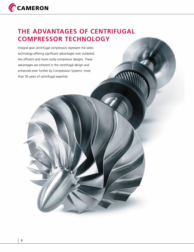
Integral gear centrifugal compressors represent the latest
technology offering significant advantages over outdated,
less efficient and more costly compressor designs. These
advantages are inherent in the centrifugal design and
enhanced even further by Compression Systems' more
than 50 years of centrifugal expertise.
2
the advantages of Centrifugal Compressor teChnology
low maintenanCe
oil-free air
no pulsation
optimum Control
no vibration

3
C o m p r e s s i o n s y s t e m s
Compare Compression Systems' innovative centrifugal compressor technology with
other machines such as rotary screw compressors and the advantages are clear:
Compression systems Centrifugal Compressors
• No wearing parts requiring regular replacement
• Oil filter elements and seal gas filter elements are easily replaced
• 100% oil free• Prevents contamination
of system
• Pulsation free and require no dampers
• Automatic operation for any operating condition
• State-of-the-art Maestro Suite of controls
• PLC control available
• Essentially vibration-free• No special foundation
is required
other Compressors
• Requires regular mainte-nance and periodic replacement of air ends
• Results in high operating expenses and significant machine downtime
• Oil filters must be installed at discharge
• Potential for oil carryover that foul the process
• Require the use of pulsa-tion dampers to reduce pressure fluctuations
• Limited control capability• Costly, high maintenance
variable speed available
• Require a large and deep foundation to handle heavy weight and unbal-anced forces
• Precautions must be taken to prevent transmission of vibration to other equipment
low maintenanCe
oil-free air
no pulsation
optimum Control
no vibration
CCV 5-Year Warranty Program
• added proteCtion
• defined Costs
• peaCe of mind
CCV is a no up-front-cost extended
5-year air end warranty for Plant
Air products. simply perform the
recommended maintenance out-
lined in the owner's manual using
Compression systems' authorized
service representatives. All main-
tenance will be logged every
quarter by your service represen-
tative on our easy-to-use online
CCV maintenance log tool.

4
simple installation
• Compressor, lubrication system,
intercoolers, shaft coupling,
coupling guard, interconnecting
piping, etc. all on a common base
• easy component accessibility
• great flexibility to tailor a
machine to your needs
• minimizes required floor space
• Pulsation free
inherent variable load Capability
Compression systems' state-of-the-art
control systems give our centrifugal
compressors inherent variable load
capability without high maintenance,
variable speed drivers. This
distinctive feature results in:
• Higher efficiency
• lower maintenance
• easier operation
oil-free air
• Prevents contamination of your system
• Removes the potential for
compressed air pipeline fires
caused by oil carryover
• Eliminates costly waste disposal
problems associated with
oil-laden condensate
• Eliminates the expense and
maintenance of oil removal filters
high reliability
Compression Systems' centrifugal compressors
are extremely reliable due to features such as:
• Thrust loads absorbed at low speed
• Stainless steel compression elements
• Conservative high-quality gear design
• Unlimited life pinion bearing design
• Non-contact air and oil seals
easy operation/maintenanCe
• State-of-the-art controls with a choice
of exclusive control systems
• Totally automatic operation for any
operating condition
• Self diagnostics
• No wearing parts requiring periodic changes
or replacement in the compression elements
• No oil removal filters to clean
• Intercooler and aftercooler bundles easily removed for cleaning
• Accessible horizontally split gear box for
quick inspection
• Water in the tube design intercoolers
allow simple mechanical cleaning
horizontal split gear box – Allows for easy access when customer’s maintenance policy requires periodic inspection.
Oil Supply
Bearing
Viscous Damper
Housing
superior pinion bearing design – for unlimited life and operation at any load.
seals – non-contact, non-wearing labyrinth air and oil seals. no buffer air required for oil-free air. eliminates the need for periodic replacement of carbon seals.
Oil Seal Air Seal
intercoolers – Water-in-tube intercooler and aftercooler bun-dles slide out for easy inspection and cleaning.
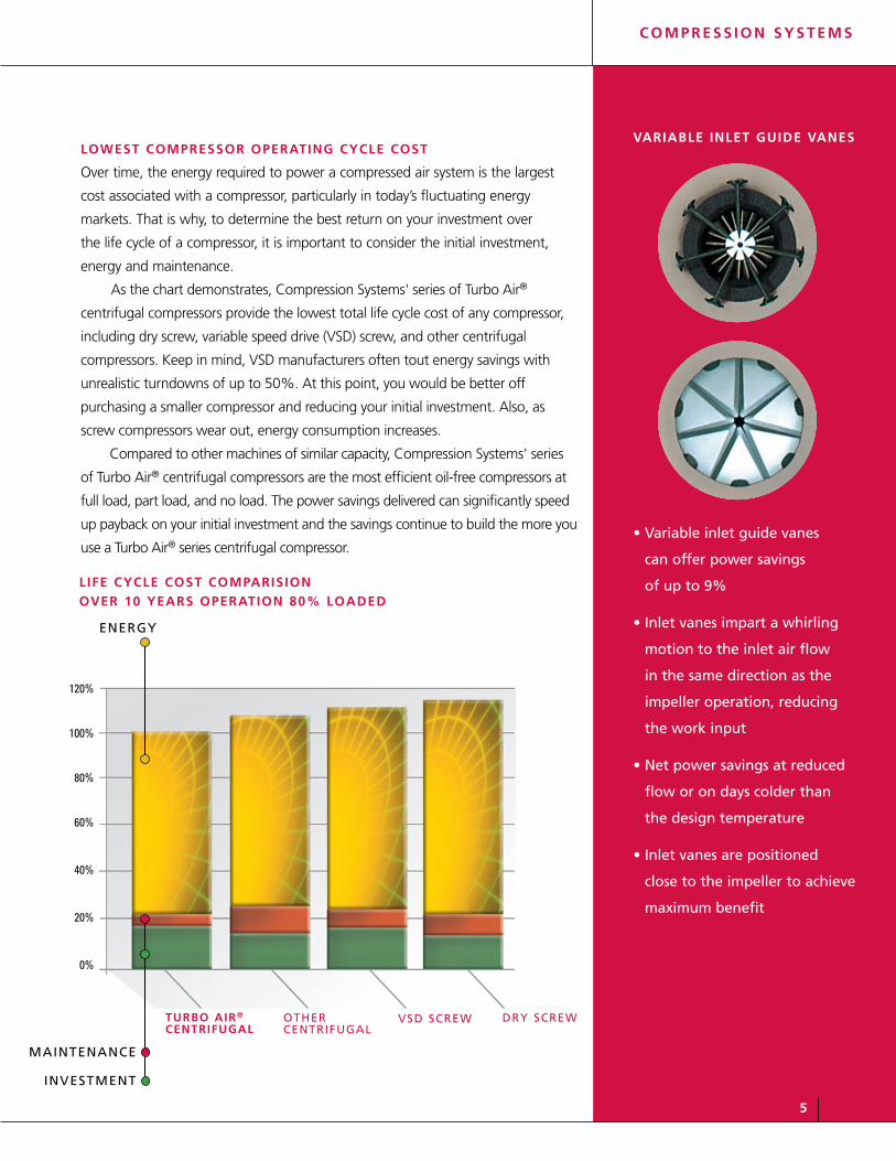
life CyCle Cost Comparision over 10 years operation 80% loaded
120%
100%
80%
60%
40%
20%
0%
mAinTenAnCe
inVesTmenT
energY
DrY sCreWVsD sCreWoTHerCenTrifugAl
turbo air®
Centrifugal
variable inlet guide vanes
• Variable inlet guide vanes
can offer power savings
of up to 9%
• inlet vanes impart a whirling
motion to the inlet air flow
in the same direction as the
impeller operation, reducing
the work input
• net power savings at reduced
flow or on days colder than
the design temperature
• inlet vanes are positioned
close to the impeller to achieve
maximum benefit
5
C o m p r e s s i o n s y s t e m s
lowest Compressor operating CyCle Cost Over time, the energy required to power a compressed air system is the largest
cost associated with a compressor, particularly in today’s fluctuating energy
markets. That is why, to determine the best return on your investment over
the life cycle of a compressor, it is important to consider the initial investment,
energy and maintenance.
As the chart demonstrates, Compression Systems' series of Turbo Air®
centrifugal compressors provide the lowest total life cycle cost of any compressor,
including dry screw, variable speed drive (VSD) screw, and other centrifugal
compressors. Keep in mind, VSD manufacturers often tout energy savings with
unrealistic turndowns of up to 50%. At this point, you would be better off
purchasing a smaller compressor and reducing your initial investment. Also, as
screw compressors wear out, energy consumption increases.
Compared to other machines of similar capacity, Compression Systems' series
of Turbo Air® centrifugal compressors are the most efficient oil-free compressors at
full load, part load, and no load. The power savings delivered can significantly speed
up payback on your initial investment and the savings continue to build the more you
use a Turbo Air® series centrifugal compressor.
6
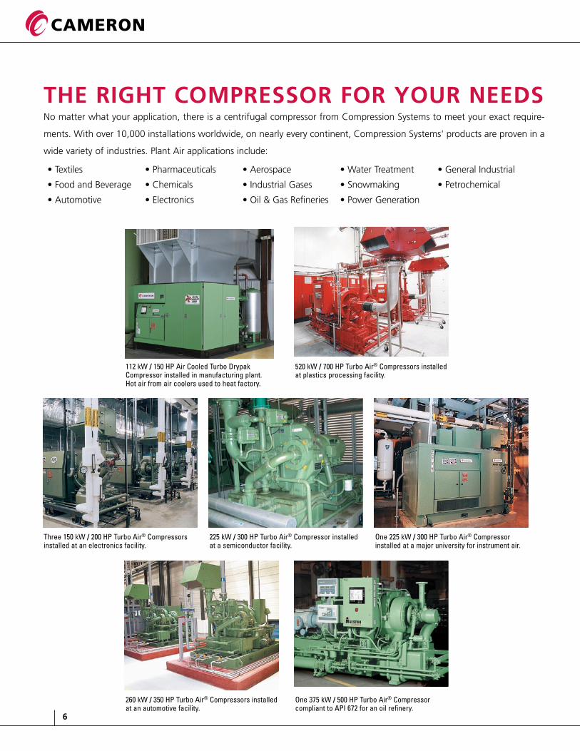
the right Compressor for your needsNo matter what your application, there is a centrifugal compressor from Compression Systems to meet your exact require-
ments. With over 10,000 installations worldwide, on nearly every continent, Compression Systems' products are proven in a
wide variety of industries. Plant Air applications include:
• Textiles
• Food and Beverage
• Automotive
• Pharmaceuticals
• Chemicals
• Electronics
• Aerospace
• Industrial Gases
• Oil & Gas Refineries
• Water Treatment
• Snowmaking
• Power Generation
• General Industrial
• Petrochemical
112 kW / 150 HP Air Cooled Turbo Drypak Compressor installed in manufacturing plant. Hot air from air coolers used to heat factory.
520 kW / 700 HP Turbo Air® Compressors installed at plastics processing facility.
260 kW / 350 HP Turbo Air® Compressors installed at an automotive facility.
One 375 kW / 500 HP Turbo Air® Compressor compliant to API 672 for an oil refinery.
Three 150 kW / 200 HP Turbo Air® Compressors installed at an electronics facility.
225 kW / 300 HP Turbo Air® Compressor installed at a semiconductor facility.
One 225 kW / 300 HP Turbo Air® Compressor installed at a major university for instrument air.

7
C o m p r e s s i o n s y s t e m s
maestrotm suite of Controls
Maestro™ is the new suite of control systems from
Cameron. The Maestro™ suite contains a model that
is sure to be in tune with your needs.
maestro™ legend
• Provides comprehensive control of your centrifugal
compressor and can be configured to coordinate the
operation of multiple compressors
• Maintain plant pressure to within 0.17-0.14 bar/1-2
PSI, which allows overall pressure reduction to improve
efficiency and reduce air leakage losses saving energy
dollars
maestro™ plC
• Utilizes an open architecture Allen Bradley PLC
which enables you to use off-the-shelf components that
match other panels in your plant
• Available in three control methods: Constant
Pressure, Auto/Dual, and Mass Flow
maestro™ eZ
• An economical control system for basic
compressor operation
• A standardized PLC solution with broad built-in
capability designed for simplified use
Compression Systems' centrifugal compressors are superior by design
Turbo Air® Series compressors offer the most advanced package
available for easy, low-cost installation and operation.

8
Dedicated Manufacturing Capabilities
Compression Systems' manufacturing facilities are among
the most advanced in the industry, utilizing leading tech-
nology operated by an experienced and skilled workforce.
Everything we do at our ISO-9001:2000 facilities is aimed
at improving quality and shortening delivery times.
manufaCturing teChnology highlights
• CAD/CAM systems
• Vertical turning centers
• Impeller milling centers – 5-axis
• Horizontal boring centers
• Cell manufacturing and work team techniques
• State-of-the-art testing facilities

9
C o m p r e s s i o n s y s t e m s
turbo air® series Compressor models
Compression Systems' revolutionary Turbo Air® centrifugal compressor offers an advanced,
state-of-the-art source of oil-free air for plant air and other applications.
turbo air® 2000 - 93-260 kW / 125 to 350 HP and 14.3-48.1 m3/min / 505 to 1700 CFMturbo air® 2020 - Two-stage 187-298 kW / 250 to 400 HP and 28-57 m3/min / 1000-2000 CFM offering best specific power of any two-stage compressor turbo air Cooledtm 2000 - 93-260 kW / 125 to 350 HP and 14.3-48.1 m3/min / 505 to 1700 CFM range. turbo air® 3000 - 298-597 kW / 400 to 800 HP and 57-113 m3/min / 2000 to 4000 CFMturbo air® 6000 - 670-1270 kW / 900 to 1700 HP and 113-226 m3/min / 4000 to 8000 CFMturbo air® 9000 - 1120-1680 kW / 1500 to 2250 HP and 184-334 m3/min / 6500 to 11800 CFMturbo drypak tm - Patented dryer and compressor package featuring adjustable dew point performancetwinturbo - Combined service compressor for dual process air and booster applications
turbo air® 2000 turbo air® 2020
turbo air Cooledtm 2000 turbo air® 3000
turbo air® 9000 turbo drypaktm and twinturbo
turbo air® 6000

10
api 672/ta-3000
Compression Systems' provides a complete line of cen-
trifugal compressors that meet API 672 requirements.
Shown is an API 672 compliant unit for an oil refinery in
Texas, USA – 2300 CFM, 500 HP, 150 PSI (65 m3/min, 375
kW, 10.3 bar).
turbo air Cooled™ 2000
Compression Systems' Turbo Air Cooled 2000 centrifu-
gal compressor is designed for applications where there
is limited or no water available for cooling. It features
innovative air-to-air cooling technology in a reliable
centrifugal design. High ambient and sub-zero ambient
packages are available.
turbo drypak™ Compressed air dryer
Compression Systems' patented dryer and compressor
package utilizes the heat-of-compression as the regenerat-
ing power to remove moisture without heaters or blowers.
Turbo DryPak features adjustable dew point performance.
twinturbo Combined serviCe Compressor
The TwinTurbo Combined Service Compressor delivers
the proven solution for dual process air and booster
applications, eliminating a compressor and reducing
installation and maintenance costs.

11
C o m p r e s s i o n s y s t e m s
01
03
08
02
04
05
07
06
Typical Air Flow Arrangement
Compression Systems' centrifugal
compressors feature a superior arrangement
of air flow components. Advantages of this
arrangement include:
• Air movement is directed so
turbulence-induced friction
is reduced
• Air is cooled after every stage
to assure a high isothermal
efficiency
Turbo Air®
01: Compressor Inlet
02: 1st Stage Compressor Scroll
03: 1st Stage Intercooler
04: 2nd Stage Compressor Scroll
05: 2nd Stage Intercooler
06: 3rd Stage Compressor Scroll
07: Compressor Discharge
08: Water Manifold (optional)
Note: This chart represents a typical flow chart schematic. For greater pressure or flow requirements, consult Compression Systems.
Pressure / Flow Schematic
ta-2000
ta-2020
ta-3000 ta-6000 ta-9000
15.5 34 48 57 113 m3/min 227 340
.55 1.2 1.7 2 4 cfmx1000 8 12
p
si
b
ar
150
125
55
10.3
8.6
3.8
12
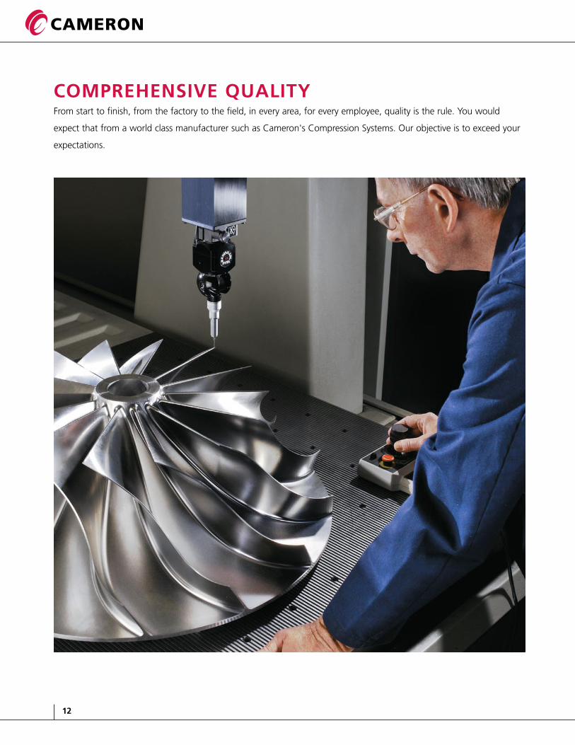
Comprehensive Quality From start to finish, from the factory to the field, in every area, for every employee, quality is the rule. You would
expect that from a world class manufacturer such as Cameron's Compression Systems. Our objective is to exceed your
expectations.

13
C o m p r e s s i o n s y s t e m s
Our Quality Policy
The key elements of Cameron’s Compression Systems'
quality policy are:
• Fully meeting customer expectations and requirements
• Providing products that equal or exceed industry and
government standards
• Providing our customers with the best value delivered
• Focusing on long term customer satisfaction
• Striving for continuous improvement
• Understanding quality is everyone’s job
Our Quality Program
iso-9001:2000 Certified Quality management system
• Systematic approach to continuous improvement
• 15 Trained ISO Internal Auditors
iso-14001:1996 Certified environmental management system
• Dedication to reducing and eliminating waste
• Providing a healthy and safe work environment
for all employees
• Meeting or exceeding all environmental, health,
and safety regulatory requirements
six sigma training
• Addressing customer critical to quality issues
• Process and product improvements most beneficial
to our customers
• Training in sophisticated
problem-solving tools
supplier Quality management
• Maintain an Approved Vendors List
• New suppliers reviewed and evaluated prior
to being added
• Supplier quality performance tracked through the non-
conforming product database within our business system
• Periodic supplier performance evaluations
Ce mark CertifiCation
• TAC2000 family of compressors was first to be certified
• Other plant air units and some engineered compressors
have been certified
pressure eQuipment direCtive – ped
• Equipment meets the PED requirements for the design
and manufacture of pressure equipment and assemblies
China pressure vessel Code CertifiCation
• Key suppliers have been certified to meet the China
Pressure Vessel Code
• Multiple units have been shipped meeting
these requirements
14
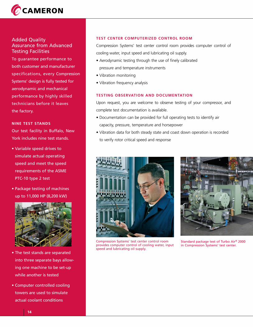
test Center ComputeriZed Control room
Compression Systems' test center control room provides computer control of
cooling water, input speed and lubricating oil supply.
• Aerodynamic testing through the use of finely calibrated
pressure and temperature instruments
• Vibration monitoring
• Vibration frequency analysis
testing observation and doCumentation
Upon request, you are welcome to observe testing of your compressor, and
complete test documentation is available.
• Documentation can be provided for full operating tests to identify air
capacity, pressure, temperature and horsepower
• Vibration data for both steady state and coast down operation is recorded
to verify rotor critical speed and response
Added Quality Assurance from Advanced Testing facilities
To guarantee performance to
both customer and manufacturer
specifications, every Compression
systems' design is fully tested for
aerodynamic and mechanical
performance by highly skilled
technicians before it leaves
the factory.
nine test stands
our test facility in Buffalo, new
York includes nine test stands.
• Variable speed drives to
simulate actual operating
speed and meet the speed
requirements of the Asme
PTC-10 type 2 test
• Package testing of machines
up to 11,000 HP (8,200 kW)
• The test stands are separated
into three separate bays allow-
ing one machine to be set-up
while another is tested
• Computer controlled cooling
towers are used to simulate
actual coolant conditions
Compression systems' test center control room provides computer control of cooling water, input speed and lubricating oil supply.
standard package test of Turbo Air® 2000 in Compression systems' test center.
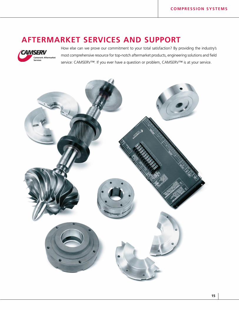
aftermarket serviCes and supportHow else can we prove our commitment to your total satisfaction? By providing the industry’s
most comprehensive resource for top-notch aftermarket products, engineering solutions and field
service: CAMSERV™. If you ever have a question or problem, CAMSERV™ is at your service.
15
C o m p r e s s i o n s y s t e m s

north ameriCanterritory
Central & south ameriCanterritory
european territory
asia paCifiC territory
worldwide Customer support organiZation
Compression Systems has over 80 representatives and
distributors worldwide to service your needs wherever your
application is located. We keep life-cycle records on every
unit we manufacture, enabling us to be a partner with
you, now and in the future.
exCeptional parts
• Genuine parts produced in the same facility for
more than 50 years
• Extensive inventory in strategic locations around
the world backed by our written warranty
• Cross-checked against unit maintenance records
to ensure correctness
elite teChniCal support
• Our goal, like yours, is to keep your unit running
• Our Technical Support is geared to do just that
installation and start up
• Concierge preventive maintenance programs
• Diagnostic and troubleshooting services
• Vibration analysis and trending
• Remote monitoring
repair expertise
• State-of-the-art-equipment for turnkey repairs
• Complete documentation package
• Strategic locations to serve a broad customer base
including Houston, TX; Los Angeles
(Garden Grove), CA; Buffalo, NY;
and Milan, Italy
faCtory training
• Comprehensive, on-site training
seminars for you and your personnel
• Instruction on a variety of topics
including Level II courses offering
hands-on training
• Courses can be tailored to your needs
at our Buffalo, NY training center
smart produCt upgrades
Compression Systems is constantly striving to improve
efficiency and enhance performance. We incorporate
these advances into retrofit kits that enable you to keep
your equipment up to date.
Controls retrofits
• Re-aero kits to improve efficiency or match
changing conditions
• Oil and cooling water system enhancements
• Motor upgrades16

17
C o m p r e s s i o n s y s t e m s
4msg-16/15 air Compressor - Application: Located in China, used as main air compressor for air separation plant. Specifications: Flow = 59,000 Nm3/hr, Discharge Pressure =1241 kPaA
3r2msgpb-5g/30 gas Compressor - Application: Located in Algeria, used as boil off compressor. API 617. Specifications: Flow = 20,000 kg/hr, Discharge Pressure = 7.47 kg/cm2A
tae-55 air Compressor - Application: Oil refinery in Texas. Powered by a Dresser Rand steam turbine. Used as an air compressor for the Olefins Plant. API 672 special service. Specifications: Flow = 6,700 SCFM, Discharge Pressure = 125 psig
fuel gas booster skid - One compressor packaged with gas scrubbers, Allen Bradley ContoLogix PLC, seal rack, motors, bypass and recirculation piping. Specifications: Flow = 69,864 MMSCFD, Discharge Pressure = 710 psia
Compression systems offers moreIn addition to our Turbo Air Series products, Compression Systems offers engineered air, industrial and process
gas centrifugal compressors, designed for specific applications with a wide range of capacities and power ranges.
Our MSG® (Multi-Stage Geared) compressors are application engineered with a number of available configurations
for flow requirements from 2720 m3/hr / 1620 CFM to 255,000 m3/hr / 150,000 CFM to over 33,500 kW / 45,000
HP and 83 bar g / 1200 psig.
4msg-16/15 air Compressor
fuel gas booster skid
3r2msgpb-5g/30 gas Compressor
tae-55 air Compressor

C o m p r e s s i o n s y s t e m s
Locations to Serve You Worldwide
headQuarters
16250 Port northwest DriveHouston, TX 77041 usA Tel 713.354.1900 fax 713.354.1923
manufaCturing & engineering
Center of exCellenCe
3101 Broadway P.o. Box 209 Buffalo, new York 14225-0209 usA Toll free: 877.805.7911Tel 716.896.6600 fax 716.896.1233
www.c-a-m.com
sales offiCes
north america3070 Bristol Pike suite 106 Bensalem, PA 19020 usA Tel 215.245.9150 fax 215.245.9170
europe/middle east/africaVia Cantu´ 8/1020092, Cinisello Balsamo (mi), italyTel 39.02.6129.2010fax 39.02.6129.4240
asia pacificno. 2 gul Circle Jurong industrial Townsingapore 629560 Tel 656.863.3631fax 656.862.1662
Tower A, room 1701-1703Chengjian Plazano. 18 Beitaipingzhuang Haidian DistrictBeijing 100088, ChinaTel 86.10.82255700fax 86.10.82255711
south americaAlameda santos, 455Conj. 212 – ParaisoCeP 01419-0000sao Paulo, BrazilTel 55.11.3284.1164fax 55.11.3284.3872
Cameron's Compression systems strives for continuous improvement in all aspects of our business. Cameron's Compression systems reserves the right to modify designs and specifications without notice or obligation. nothing contained in this brochure is intended to extend any type of warranty, expressed or implied.
©2007 Cameron international Corporation | Compression systems Division | 1/07
1/07 10m Printed in usA