Embed Size (px)
Citation preview
Planning-Level Guidelines for Modern Roundabouts
Technical MemorandumNovember 2008
Sponsored bythe Iowa Department of Transportation (CTRE Project 06-255)
Iowa State University’s Center for Transportation Research and Education is the umbrella organization for the following centers and programs: Bridge Engineering Center • Center for Weather Impacts on Mobility
and Safety • Construction Management & Technology • Iowa Local Technical Assistance Program • Iowa Traffic Safety Data Service • Midwest Transportation Consortium • National Concrete Pavement
Technology Center • Partnership for Geotechnical Advancement • Roadway Infrastructure Management and Operations Systems • Statewide Urban Design and Specifications • Traffic Safety and Operations
About CTRE/ISU
The mission of the Center for Transportation Research and Education (CTRE) at Iowa State Uni-versity is to develop and implement innovative methods, materials, and technologies for improv-ing transportation efficiency, safety, and reliability while improving the learning environment of students, faculty, and staff in transportation-related fields.
Disclaimer Notice
The contents of this report reflect the views of the authors, who are responsible for the facts and the accuracy of the information presented herein. The opinions, findings and conclusions expressed in this publication are those of the authors and not necessarily those of the sponsors.
The sponsors assume no liability for the contents or use of the information contained in this document. This report does not constitute a standard, specification, or regulation.
The sponsors do not endorse products or manufacturers. Trademarks or manufacturers’ names appear in this report only because they are considered essential to the objective of the document.
Non-discrimination Statement
Iowa State University does not discriminate on the basis of race, color, age, religion, national origin, sexual orientation, gender identity, sex, marital status, disability, or status as a U.S. veteran. Inquiries can be directed to the Director of Equal Opportunity and Diversity, (515) 294-7612.
Technical Report Documentation Page
1. Report No. 2. Government Accession No. 3. Recipient’s Catalog No. CTRE Project 06-255
4. Title and Subtitle 5. Report Date November 2008 6. Performing Organization Code
Planning-Level Guidelines for Modern Roundabouts
7. Author(s) 8. Performing Organization Report No. Hillary N. Isebrands and Shauna Hallmark 9. Performing Organization Name and Address 10. Work Unit No. (TRAIS)
11. Contract or Grant No.
Center for Transportation Research and Education Iowa State University 2711 South Loop Drive, Suite 4700 Ames, IA 50010-8664
12. Sponsoring Organization Name and Address 13. Type of Report and Period Covered Technical Memorandum 14. Sponsoring Agency Code
Iowa Department of Transportation 800 Lincoln Way Ames, IA 50010 15. Supplementary Notes Visit www.ctre.iastate.edu for color PDF files of this and other research reports. 16. Abstract This technical memorandum provides preliminary planning-level guidance to engineers, technicians, planners, and policymakers who may be considering a modern roundabout at an existing or proposed intersection in Iowa.
17. Key Words 18. Distribution Statement intersections—planning-level guidance—roundabouts No restrictions. 19. Security Classification (of this report)
20. Security Classification (of this page)
21. No. of Pages 22. Price
Unclassified. Unclassified. 30 NA
Form DOT F 1700.7 (8-72) Reproduction of completed page authorized

PLANNING-LEVEL GUIDELINES FOR MODERN ROUNDABOUTS
Technical Memorandum
November 2008
Principal Investigator Shauna Hallmark
Transportation Engineer Center for Transportation Research and Education, Iowa State University
Graduate Research Assistant
Hillary Isebrands
Iowa Department of Transportation Roundabout Task Force John Abrams, Iowa Department of Transportation, Office of Design
Brad Hofer, Iowa Department of Transportation, Location and Environment Shauna Hallmark, Iowa State University Hillary Isebrands, Iowa State University
Dave Little, Iowa Department of Transportation, District 2, Assistant District Engineer Deanna Maifield, Iowa Department of Transportation, Office of Design
Dan Ohman, Iowa Department of Transportation, Office of Design Tim Simodynes, Iowa Department of Transportation, Office of Traffic and Safety
Jeremey Vortherms, Iowa Department of Transportation, Office of Traffic and Safety Lorne Wazny, Iowa Department of Transportation, District 1 Planner
Andy Wilson, Federal Highway Administration Ken Yanna, Iowa Department of Transportation, District 6 Local Systems
Kurtis Yonkin, Iowa Department of Transportation
Preparation of this report was financed in part through funds provided by the Iowa Department of Transportation
through its research management agreement with the Center for Transportation Research and Education,
CTRE Project 06-255.
A report from Center for Transportation Research and Education
Iowa State University 2711 South Loop Drive, Suite 4700
Ames, IA 50010-8664 Phone: 515-294-8103 Fax: 515-294-0467
www.ctre.iastate.edu

v
TABLE OF CONTENTS
ACKNOWLEDGMENTS ............................................................................................................ IX
GENERAL INFORMATION..........................................................................................................1
CLASSIFICATION .........................................................................................................................2
KEY ROUNDABOUT FEATURES AND GEOMETRIC ELEMENTS .......................................4
EDUCATION ..................................................................................................................................9
SAFETY ........................................................................................................................................10
OPERATIONS AND DESIGN .....................................................................................................12
CONSIDERATIONS AND FEASIBILITY ..................................................................................14
FOR MORE INFORMATION ......................................................................................................19
PEER REVIEW AVAILABLE THROUGH OFFICE OF TRAFFIC AND SAFETY.................19
REFERENCES AND RESOURCES.............................................................................................20

vii
LIST OF FIGURES
Figure 1. Roundabout features (Photo courtesy of Hillary Isebrands) ............................................4 Figure 2. Key roundabout geometric elements (Photo courtesy of Hillary Isebrands) ...................6 Figure 3. Typical bike ramp (left), outside curbing on the approach (right) (Photos courtesy of
Hillary Isebrands) ................................................................................................................6 Figure 4. Vehicle path radii .............................................................................................................8 Figure 5. Roundabout design that encourages vehicle path overlap, aerial view (left) and driver’s
view (right) ..........................................................................................................................8 Figure 6. Intersection vehicle-vehicle conflict points....................................................................10 Figure 7. Maximum daily service volumes for four-leg roundabouts ...........................................13
LIST OF TABLES
Table 1. Comparison of old-style rotaries, neighborhood traffic calming circles, and modern roundabouts..........................................................................................................................3
Table 2. Key roundabout features....................................................................................................5 Table 3. Key roundabout geometric elements .................................................................................7 Table 4. Before and after analysis of crashes ................................................................................11 Table 5. Average delay per vehicle considering volume and left turns.........................................12 Table 6. Important factors when considering a roundabout ..........................................................15


ix
ACKNOWLEDGMENTS
The authors would like to thank the Iowa Department of Transportation for sponsoring this research.

GENERAL INFORMATION
This technical memorandum provides preliminary planning-level guidance to engineers, technicians, planners, and policymakers who may be considering a modern roundabout at an existing or proposed intersection in Iowa.
Federal Highway Administration (FHWA) document FHWA-RD-00-067, Roundabouts: An Informational Guide (Robinson et al. 2000), is the most comprehensive document available for roundabout planning and design in the United States. Throughout this memorandum, this document will be referred to as the FHWA Guide. Further roundabout research that supplements and enhances the FHWA Guide, including NCHRP 572, Roundabouts in the United States (2007); several state department of transportation (DOT) documents; and the proposed amendments to the Manual on Uniform Traffic Control Devices (MUTCD) (FHWA 2008), are also available. An update to the FHWA Guide is expected in 2010.
1

CLASSIFICATION
A modern roundabout is one of three types of circular intersections. Circular intersections include “old-style” rotaries, neighborhood traffic circles, and modern roundabouts. Modern roundabouts are frequently confused with rotaries (e.g., DuPont Circle in Washington, DC) and neighborhood traffic calming circles. However, there are significant differences among the three types of traffic circles.
Old-style rotaries have the largest diameters (over 300 ft) of the three circular intersections. Vehicle speeds tend to be less uniform because the large-diameter circulatory roadways allow for higher speeds (30+ mph) and the more perpendicular angles at the approaches to the circulatory roadways produce lower speeds at the entries. Additionally, circulating traffic is not given priority over entering traffic, which causes vehicles to queue within the roundabout. Many old-style rotaries are being replaced by modern roundabouts because the rotaries tend to have poor crash histories and operational problems.
Neighborhood traffic circles are built on local roadways, often for traffic calming purposes. Therefore, these traffic circles are often referred to as neighborhood traffic calming circles. Typically, the intersection at which the traffic circle is installed is only modified to include a raised center island and raised channelization (splitter islands). Approach deflection is rarely used. Neighborhood traffic calming circles are known to slow traffic speeds along the local roadways at the intersection, but the circles often cannot accommodate all movements for large trucks.
Modern roundabouts slow all vehicles to speeds that are typically between 10 and 25 mph. The roundabouts’ geometry and the use of channelized approaches (splitter islands and an outside curb) help deflect vehicles as they approach and enter the circulating roadway. One of the basic principles of modern roundabouts is “yield at entry.” Drivers approaching the circular intersection must yield at the entry if an acceptable gap is not available to enter the circulating roadway. If an acceptable gap is available, the driver may proceed into the circulatory roadway without stopping. However, drivers stopping at the yield line when there are no circulating vehicles can have a negative effect on capacity.
Table 1 compares the characteristics of old-style rotaries, neighborhood traffic circles, and modern roundabouts (FHWA 2000; WisDOT 2008; Mundell and Grigsby 1998; Kittelson & Associates 2003). Throughout the rest of the document, the modern roundabout will be referred to simply as roundabout.
2
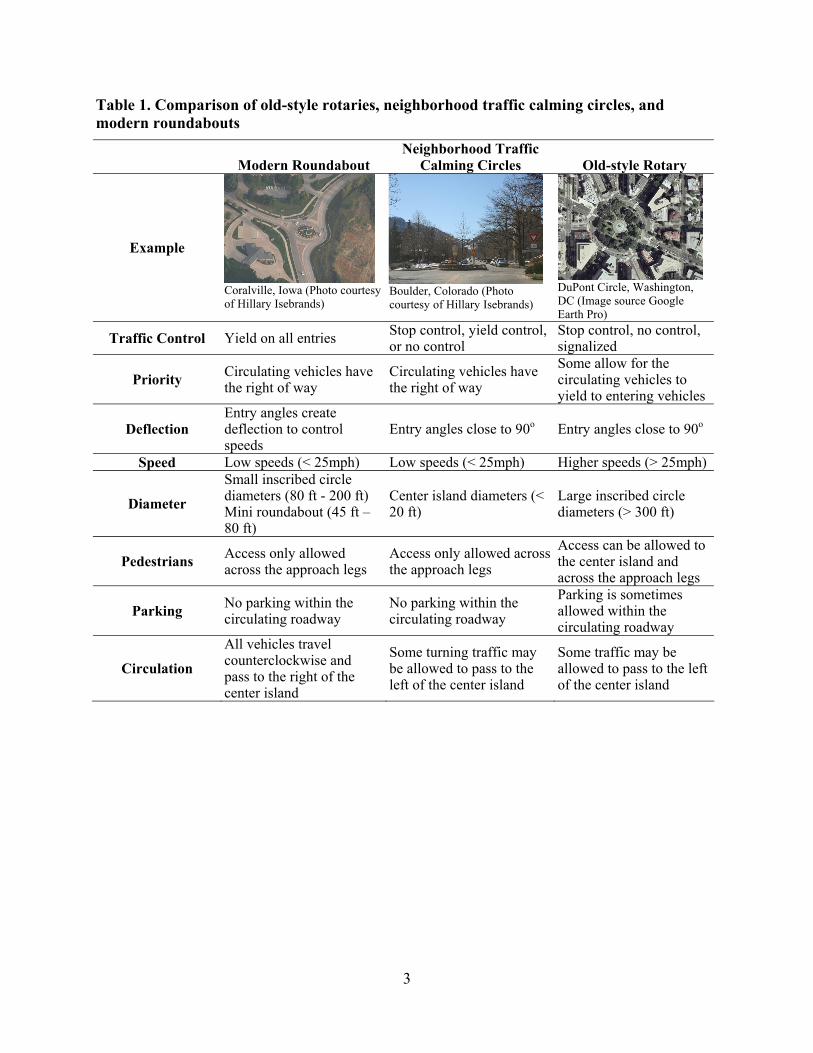
Table 1. Comparison of old-style rotaries, neighborhood traffic calming circles, and modern roundabouts
Modern Roundabout Neighborhood Traffic
Calming Circles Old-style Rotary
Example
Coralville, Iowa (Photo courtesy of Hillary Isebrands)
Boulder, Colorado (Photo courtesy of Hillary Isebrands)
DuPont Circle, Washington, DC (Image source Google Earth Pro)
Traffic Control Yield on all entries Stop control, yield control, or no control
Stop control, no control, signalized
Priority Circulating vehicles have the right of way
Circulating vehicles have the right of way
Some allow for the circulating vehicles to yield to entering vehicles
Deflection Entry angles create deflection to control speeds
Entry angles close to 90o Entry angles close to 90o
Speed Low speeds (< 25mph) Low speeds (< 25mph) Higher speeds (> 25mph)
Diameter
Small inscribed circle diameters (80 ft - 200 ft) Mini roundabout (45 ft – 80 ft)
Center island diameters (< 20 ft)
Large inscribed circle diameters (> 300 ft)
Pedestrians Access only allowed across the approach legs
Access only allowed across the approach legs
Access can be allowed to the center island and across the approach legs
Parking No parking within the circulating roadway
No parking within the circulating roadway
Parking is sometimes allowed within the circulating roadway
Circulation
All vehicles travel counterclockwise and pass to the right of the center island
Some turning traffic may be allowed to pass to the left of the center island
Some traffic may be allowed to pass to the left of the center island
3
KEY ROUNDABOUT FEATURES AND GEOMETRIC ELEMENTS
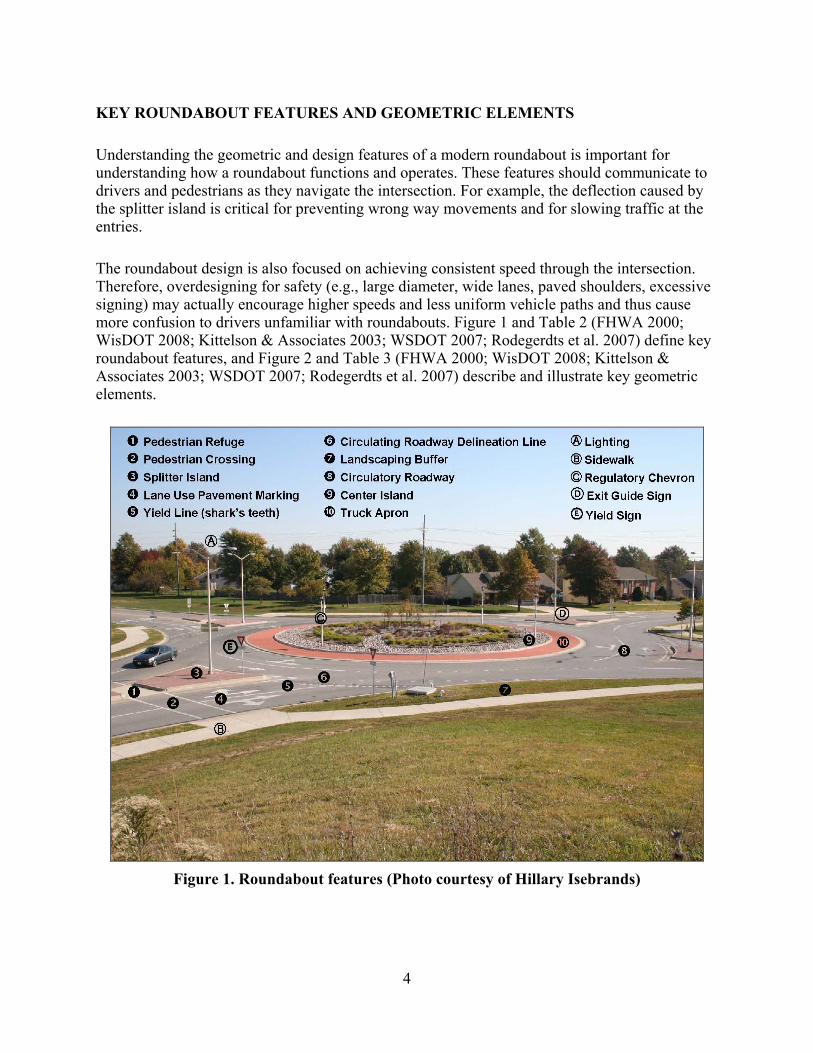
Understanding the geometric and design features of a modern roundabout is important for understanding how a roundabout functions and operates. These features should communicate to drivers and pedestrians as they navigate the intersection. For example, the deflection caused by the splitter island is critical for preventing wrong way movements and for slowing traffic at the entries.
The roundabout design is also focused on achieving consistent speed through the intersection. Therefore, overdesigning for safety (e.g., large diameter, wide lanes, paved shoulders, excessive signing) may actually encourage higher speeds and less uniform vehicle paths and thus cause more confusion to drivers unfamiliar with roundabouts. Figure 1 and Table 2 (FHWA 2000; WisDOT 2008; Kittelson & Associates 2003; WSDOT 2007; Rodegerdts et al. 2007) define key roundabout features, and Figure 2 and Table 3 (FHWA 2000; WisDOT 2008; Kittelson & Associates 2003; WSDOT 2007; Rodegerdts et al. 2007) describe and illustrate key geometric elements.
Figure 1. Roundabout features (Photo courtesy of Hillary Isebrands)
4
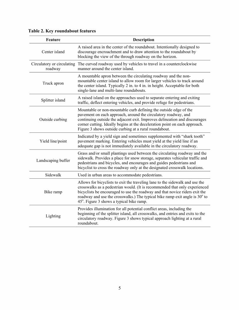
Table 2. Key roundabout features
Feature Description
Center island A raised area in the center of the roundabout. Intentionally designed to discourage encroachment and to draw attention to the roundabout by blocking the view of the through roadway on the horizon.
Circulatory or circulating roadway
The curved roadway used by vehicles to travel in a counterclockwise manner around the center island.
Truck apron
A mountable apron between the circulating roadway and the non- mountable center island to allow room for larger vehicles to track around the center island. Typically 2 in. to 4 in. in height. Acceptable for both single-lane and multi-lane roundabouts.
Splitter island A raised island on the approaches used to separate entering and exiting traffic, deflect entering vehicles, and provide refuge for pedestrians.
Outside curbing
Mountable or non-mountable curb defining the outside edge of the pavement on each approach, around the circulatory roadway, and continuing outside the adjacent exit. Improves delineation and discourages corner cutting. Ideally begins at the deceleration point on each approach. Figure 3 shows outside curbing at a rural roundabout.
Yield line/point Indicated by a yield sign and sometimes supplemented with “shark tooth” pavement marking. Entering vehicles must yield at the yield line if an adequate gap is not immediately available in the circulatory roadway.
Landscaping buffer
Grass and/or small plantings used between the circulating roadway and the sidewalk. Provides a place for snow storage, separates vehicular traffic and pedestrians and bicycles, and encourages and guides pedestrians and bicyclist to cross the roadway only at the designated crosswalk locations.
Sidewalk Used in urban areas to accommodate pedestrians.
Bike ramp
Allows for bicyclists to exit the traveling lane to the sidewalk and use the crosswalks as a pedestrian would. (It is recommended that only experienced bicyclists be encouraged to use the roadway and that novice riders exit the roadway and use the crosswalks.) The typical bike ramp exit angle is 30o to 45o. Figure 3 shows a typical bike ramp.
Lighting
Provides illumination for all potential conflict areas, including the beginning of the splitter island, all crosswalks, and entries and exits to the circulatory roadway. Figure 3 shows typical approach lighting at a rural roundabout.
5
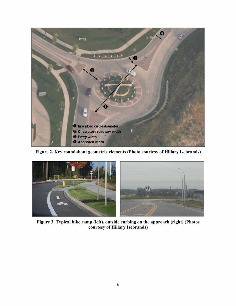
Figure 2. Key roundabout geometric elements (Photo courtesy of Hillary Isebrands)
Figure 3. Typical bike ramp (left), outside curbing on the approach (right) (Photos courtesy of Hillary Isebrands)
6
Table 3. Key roundabout geometric elements
Element Description
Inscribed circle diameter (ICD)
Defines the size of the roundabout, measured between the outer edges of the circulatory roadway. Typically 100 to 130 ft for single-lane roundabouts and 150 to 180 ft for double-lane roundabouts, but varies based on design vehicle turning radius and intersection layout.
Circulating or circulatory roadway
width
The width of the circulatory roadway between the outer edge of the curbed roadway and the curbed center island or truck apron. It does not include the width of the truck apron and is typically between 1.0 and 1.2 times the maximum entry width.
Approach width Roadway width used by the approaching traffic. Typically 12 ft per lane. Shoulders and wide lanes can lead to undesirably high speeds.
Entry width
Width at the entry to the circulating roadway (where the approach meets the inscribed circle), measured perpendicularly from the right face of the curb to the left face of the curb. Typically 14 to 18 ft for a single-lane entry, but varies on design vehicle turning radius.
Entry flare The widening of an approach lane from the standard lane width to a wider entry width. Flare can increase capacity and accommodate off-tracking of large trucks, but decreases path definition and increases speed variance.
Deflection Entry deflection helps control vehicle speeds and prevents wrong-way movements on the circulatory roadway.
Design speed, entry The recommended maximum entry design speed is 25 mph (rural) and 20 mph (urban) for single-lane roundabouts and 25 mph for multi-lane roundabouts.
Vehicle path radii
The roundabout design speed is based on the fastest movement through the roundabout. However, speed consistency is important for all the movements. R1, the minimum radius on the fastest through path prior to the yield line, and R5, the minimum radius on the fastest path of a right-turning vehicle, are typically the most critical radii for design speed. Figure 4 (FHWA 2000, Exhibit 6-12, p. 139) shows the five vehicle path radii.
Fastest path
Determines the speed of the roundabout. The fastest path of a single vehicle, excluding all other traffic and lane markings, traversing from the entry, around the circulating roadway, and through the exit. This is usually associated with the through movement but can also be the right-turn movement.
Natural path The path an approaching vehicle will take through a multi-lane roundabout, assuming traffic in all lanes. The speed and orientation of the vehicle at the yield line determines the natural path.
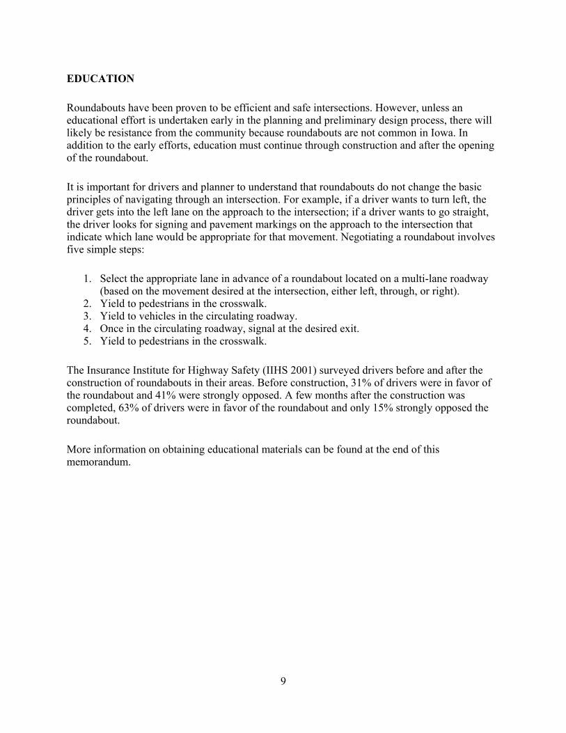
Vehicle path overlap
Path overlap occurs on multi-lane roundabouts when the natural path through the roundabout of one vehicle overlaps that of another vehicle. Occurs most commonly on the approach when a vehicle in the right lane cuts off a vehicle in the left lane as the vehicle enters the circulating lane. Figure 5 shows examples of vehicle path overlap.
7
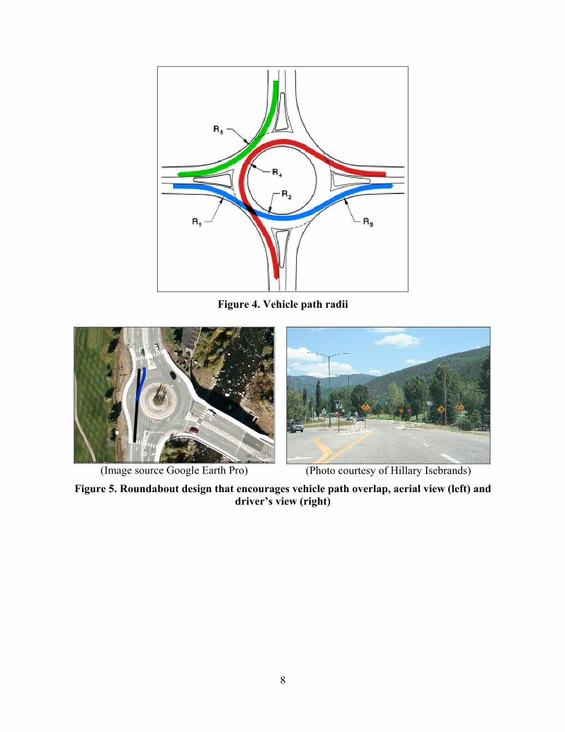
Figure 4. Vehicle path radii
(Image source Google Earth Pro)
(Photo courtesy of Hillary Isebrands) Figure 5. Roundabout design that encourages vehicle path overlap, aerial view (left) and
driver’s view (right)
8
EDUCATION
Roundabouts have been proven to be efficient and safe intersections. However, unless an educational effort is undertaken early in the planning and preliminary design process, there will likely be resistance from the community because roundabouts are not common in Iowa. In addition to the early efforts, education must continue through construction and after the opening of the roundabout.
It is important for drivers and planner to understand that roundabouts do not change the basic principles of navigating through an intersection. For example, if a driver wants to turn left, the driver gets into the left lane on the approach to the intersection; if a driver wants to go straight, the driver looks for signing and pavement markings on the approach to the intersection that indicate which lane would be appropriate for that movement. Negotiating a roundabout involves five simple steps:
1. Select the appropriate lane in advance of a roundabout located on a multi-lane roadway (based on the movement desired at the intersection, either left, through, or right).
2. Yield to pedestrians in the crosswalk. 3. Yield to vehicles in the circulating roadway. 4. Once in the circulating roadway, signal at the desired exit. 5. Yield to pedestrians in the crosswalk.
The Insurance Institute for Highway Safety (IIHS 2001) surveyed drivers before and after the construction of roundabouts in their areas. Before construction, 31% of drivers were in favor of the roundabout and 41% were strongly opposed. A few months after the construction was completed, 63% of drivers were in favor of the roundabout and only 15% strongly opposed the roundabout.
More information on obtaining educational materials can be found at the end of this memorandum.
9
SAFETY
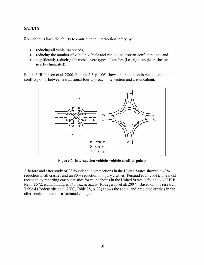
Roundabouts have the ability to contribute to intersection safety by
• reducing all vehicular speeds, • reducing the number of vehicle-vehicle and vehicle-pedestrian conflict points, and • significantly reducing the most severe types of crashes (i.e., right-angle crashes are
nearly eliminated).
Figure 6 (Robinson et al. 2000, Exhibit 5-2, p. 106) shows the reduction in vehicle-vehicle conflict points between a traditional four-approach intersection and a roundabout.
Figure 6. Intersection vehicle-vehicle conflict points
A before and after study of 23 roundabout intersections in the United States showed a 40% reduction in all crashes and an 80% reduction in injury crashes (Persuad et al. 2001). The most recent study reporting crash statistics for roundabouts in the United States is found in NCHRP Report 572, Roundabouts in the United States (Rodegerdts et al. 2007). Based on this research, Table 4 (Rodegerdts et al. 2007, Table 28, p. 33) shows the actual and predicted crashes in the after condition and the associated change.
10
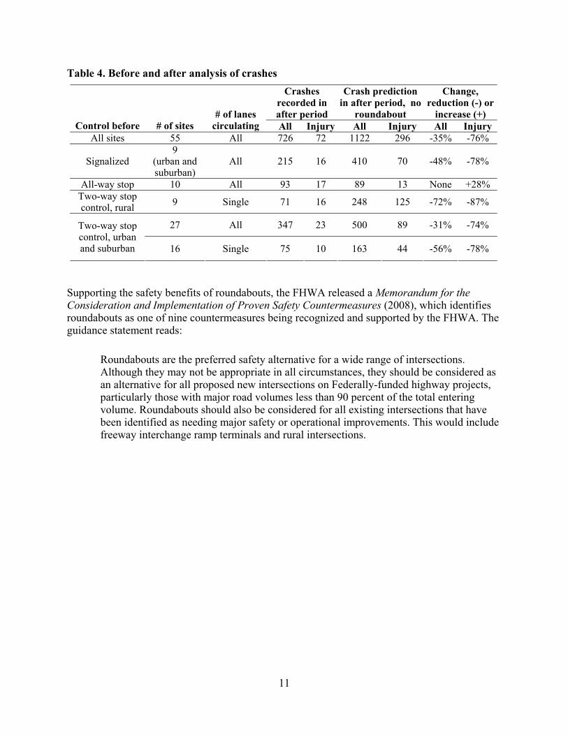
Table 4. Before and after analysis of crashes Crashes
recorded in after period
Crash prediction in after period, no
roundabout
Change, reduction (-) or
increase (+) Control before # of sites
# of lanes circulating All Injury All Injury All Injury
All sites 55 All 726 72 1122 296 -35% -76%
Signalized 9
(urban and suburban)
All 215 16 410 70 -48% -78%
All-way stop 10 All 93 17 89 13 None +28% Two-way stop control, rural 9 Single 71 16 248 125 -72% -87%
27 All 347 23 500 89 -31% -74% Two-way stop control, urban and suburban 16 Single 75 10 163 44 -56% -78%
Supporting the safety benefits of roundabouts, the FHWA released a Memorandum for the Consideration and Implementation of Proven Safety Countermeasures (2008), which identifies roundabouts as one of nine countermeasures being recognized and supported by the FHWA. The guidance statement reads:
Roundabouts are the preferred safety alternative for a wide range of intersections. Although they may not be appropriate in all circumstances, they should be considered as an alternative for all proposed new intersections on Federally-funded highway projects, particularly those with major road volumes less than 90 percent of the total entering volume. Roundabouts should also be considered for all existing intersections that have been identified as needing major safety or operational improvements. This would include freeway interchange ramp terminals and rural intersections.
11

OPERATIONS AND DESIGN
Roundabouts typically operate with lower vehicle delays than traditional intersections at capacity (Robinson et al. 2000). As vehicles approach a roundabout intersection, it is not necessary to come to a complete stop at the yield line unless there is not a large enough traffic gap within the circulatory roadway. This fundamental function of a roundabout contributes to its efficient operation and the resulting reduction in delays. Table 5 shows examples of average delays per vehicle (excluding geometric delay) at the MUTCD peak-hour signal warrant threshold, which takes into account the percentage of left-turning vehicles and vehicles per hour (vph). The information provided in Table 5 was extracted from the FHWA Guide (Robinson et al. 2000, Exhibit 3-7, p. 63).
Table 5. Average delay per vehicle considering volume and left turns Average delay per vehicle (sec) Left turns (%)
Total major street volume (vph) Signal Roundabout
Example 1 10 700 13 <2 Example 2 10 1,000 14 <2 Example 3 10 1,300 14 <2 Example 4 10 1,500 15 <2 Example 5 50 700 15 3 Example 6 50 1,000 16 3 Example 7 50 1,300 17 5 Example 8 50 1,500 19 8
The FHWA provides “rule of thumb” hourly approach volume capacities for single- and double-lane roundabouts. For this analysis, the entering volume is defined by the volume of vehicles that will be entering the circulating roadway from a specific approach (i.e., the sum of through, left, right, and U-turn). The circulating volume is the volume of traffic that will be passing by that approach. The following estimates of hourly approach volume capacities at roundabouts can be used to help determine the number of circulating lanes needed:
Single-lane approach: entering volume + circulating volume < 1,200 vph Double-lane approach: entering volume + circulating volume < 2,000 vph
For example, if the traffic volumes for an intersection show that one or more of the approaches has an entering plus circulating volume near 1,200 vph, a single-lane roundabout may not have enough capacity for that intersection; a hybrid (part one-lane and part two-lane, depending on movements) or multi-lane roundabout may be needed to handle the traffic volumes.
For more detailed information about entering and circulating volumes, see the FHWA Guide (Robinson et al. 2000).
The FHWA Guide (Robinson et al. 2000) indicates a typical daily service volume of 20,000 vehicles per day (vpd) for a single-lane roundabout with four approach legs. (The daily service
12

volume can be found by summing the two-way annual average daily traffic [AADT] volumes of all approaches and dividing by two.) Figure 7 (Robinson et al. 2000, Exhibit 3-1, p. 57) provides a conservative planning-level estimate using maximum daily service volumes for a four-leg roundabout.
Figure 7. Maximum daily service volumes for four-leg roundabouts
Additionally, WisDOT (2008) suggests the following planning-level entry capacities:
• “Single-lane roundabouts can be expected to handle an AADT of approximately 25,000 vpd and peak-hour flows between 2,000 vph and 2,500 vph.”
• “Multi-lane roundabouts (two- and three-lane entries) can be expected to handle AADTs between 25,000 and 55,000 vpd and peak-hour flows between 2,500 vph and 5,500 vph.”
13
CONSIDERATIONS AND FEASIBILITY
As with any intersection design, safety, operational, economic, and environmental concerns need to be considered when evaluating alternatives. Balancing competing needs is important and essential. Every intersection should be evaluated based on site-specific issues as well as the intersection’s relationship to the adjacent roadway network to assure the most efficient and safe intersection alternative.
While single-lane roundabouts tend to be more forgiving with respect to minor design flaws, multi-lane roundabout design requires more experience to balance many design elements into a composition that clearly and intuitively leads drivers through the intersection at uniform speeds. Elements such as lane widths, approach alignment, deflection angles, curve radii, curb design, signing, and pavement markings become much more important to the design and overall success of a multi-lane roundabout project.
The consideration, investigation, and recommendation of an intersection alternative all require good design and engineering judgment. Table 6 provides guidance and supporting information on factors related to the feasibility of roundabouts. The following rating system is used in Table 6 to define the three categories:
Generally advantageous
Roundabouts are typically advantageous where this condition exists and should be considered along with other alternatives.
Additional
investigation required
Roundabouts can be a viable alternative where this condition exists. However, a more detailed evaluation will likely be needed to determine if the roundabout is the preferred alternative.
Not recommended Roundabouts are not recommended where this condition exists.
The presence of one or more factors for which a roundabout alternative would be not recommended suggests that these factors need to be carefully considered when choosing an alternative. However, such factors do not necessarily preclude a roundabout alternative from further consideration.
14
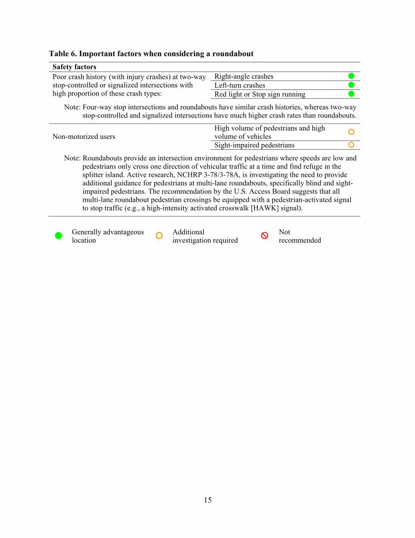
Table 6. Important factors when considering a roundabout Safety factors
Right-angle crashes Left-turn crashes
Poor crash history (with injury crashes) at two-way stop-controlled or signalized intersections with high proportion of these crash types: Red light or Stop sign running
Note: Four-way stop intersections and roundabouts have similar crash histories, whereas two-way stop-controlled and signalized intersections have much higher crash rates than roundabouts.
High volume of pedestrians and high volume of vehicles Non-motorized users Sight-impaired pedestrians
Note: Roundabouts provide an intersection environment for pedestrians where speeds are low and pedestrians only cross one direction of vehicular traffic at a time and find refuge in the splitter island. Active research, NCHRP 3-78/3-78A, is investigating the need to provide additional guidance for pedestrians at multi-lane roundabouts, specifically blind and sight-impaired pedestrians. The recommendation by the U.S. Access Board suggests that all multi-lane roundabout pedestrian crossings be equipped with a pedestrian-activated signal to stop traffic (e.g., a high-intensity activated crosswalk [HAWK] signal).
Generally advantageous location Additional
investigation required Not recommended
15
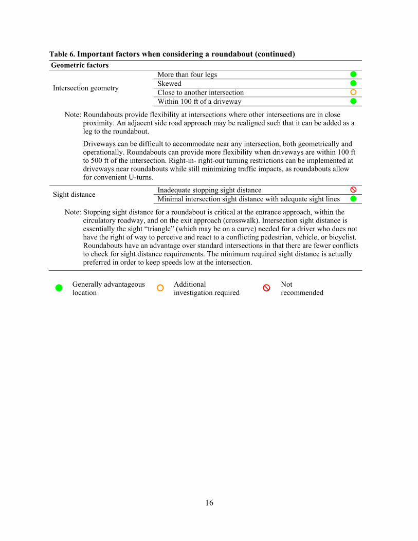
Table 6. Important factors when considering a roundabout (continued) Geometric factors
More than four legs Skewed Close to another intersection Intersection geometry
Within 100 ft of a driveway Note: Roundabouts provide flexibility at intersections where other intersections are in close
proximity. An adjacent side road approach may be realigned such that it can be added as a leg to the roundabout. Driveways can be difficult to accommodate near any intersection, both geometrically and operationally. Roundabouts can provide more flexibility when driveways are within 100 ft to 500 ft of the intersection. Right-in- right-out turning restrictions can be implemented at driveways near roundabouts while still minimizing traffic impacts, as roundabouts allow for convenient U-turns.
Inadequate stopping sight distance Sight distance Minimal intersection sight distance with adequate sight lines Note: Stopping sight distance for a roundabout is critical at the entrance approach, within the
circulatory roadway, and on the exit approach (crosswalk). Intersection sight distance is essentially the sight “triangle” (which may be on a curve) needed for a driver who does not have the right of way to perceive and react to a conflicting pedestrian, vehicle, or bicyclist. Roundabouts have an advantage over standard intersections in that there are fewer conflicts to check for sight distance requirements. The minimum required sight distance is actually preferred in order to keep speeds low at the intersection.
Generally advantageous
location Additional investigation required Not
recommended
16

Table 6. Important factors when considering a roundabout (continued) Operations
Where queuing may extend into other intersections Within a coordinated signal system Near traffic signals Where modifications to traffic via signal timing is desired
Note: Traffic signals and roundabouts can and do exist on the same corridor. Intersections on corridors need to be considered as part of a system and not on an individual or isolated basis. With proper signal timing, coordination, and an operations analysis to account for queuing between intersections, roundabouts and signalized intersections can be compatible.
Major movement - peak hours Minor movement - peak hours Major movement - off-peak hours Two way stop delay for Minor movement - off-peak hours Peak hours
Four way stop delay Off- peak hours Major movement – peak hours Minor movement – peak hours Major movement – off-peak hours Minor movement – off-peak hours No left-turn lane
Signal delay for
No protected left-turn phase High percentage of vehicles turning left Major traffic movement changes direction Turning movements In lieu of right turn on red Need for U-turns Access management Right-in-right-out restrictions
Note: Access management principles align with how roundabouts function and operate. Corridors that are hampered with numerous accesses, especially those to businesses, can benefit from roundabouts. Roundabouts facilitate the use of U-turns at intersections and allow for right turns into driveways and parking lots rather than left turns across traffic. The impacts of right-in-right-out restrictions and closed medians become reduced when roundabouts provide a natural U-turn at an adjacent intersection.
Exit ramps with a high number of left turns Limited storage on ramp
Interchange ramps Where headway between vehicles is important as vehicles enter a freeway/expressway
Generally advantageous location Additional
investigation required Not recommended
17
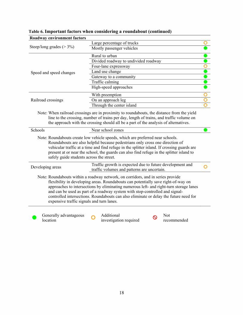
Table 6. Important factors when considering a roundabout (continued) Roadway environment factors
Large percentage of trucks Steep/long grades (> 3%) Mostly passenger vehicles
Rural to urban Divided roadway to undivided roadway Four-lane expressway Land use change Gateway to a community Traffic calming
Speed and speed changes
High-speed approaches With preemption On an approach leg Railroad crossings Through the center island
Note: When railroad crossings are in proximity to roundabouts, the distance from the yield line to the crossing, number of trains per day, length of trains, and traffic volume on the approach with the crossing should all be a part of the analysis of alternatives.
Schools Near school zones Note: Roundabouts create low vehicle speeds, which are preferred near schools.
Roundabouts are also helpful because pedestrians only cross one direction of vehicular traffic at a time and find refuge in the splitter island. If crossing guards are present at or near the school, the guards can also find refuge in the splitter island to safely guide students across the street.
Developing areas Traffic growth is expected due to future development and traffic volumes and patterns are uncertain.
Note: Roundabouts within a roadway network, on corridors, and in series provide flexibility in developing areas. Roundabouts can potentially save right-of-way on approaches to intersections by eliminating numerous left- and right-turn storage lanes and can be used as part of a roadway system with stop-controlled and signal-controlled intersections. Roundabouts can also eliminate or delay the future need for expensive traffic signals and turn lanes.
Generally advantageous location Additional
investigation required Not recommended
18

Table 6. Important factors when considering a roundabout (continued) Right-of-way factors
At the intersection Limitations On approaches (storage, turn lanes)
Note: Roundabouts fit the “wide nodes and narrow roads” concept. The approaches at roundabouts do not require additional right-of-way for left- and right-turn lanes that a traditional intersection may require. Mini roundabouts also provide flexibility where right-of-way is limited.
Generally advantageous
location Additional investigation required Not
recommended
FOR MORE INFORMATION
Deanna Maifield, P.E. Tim Simodynes, P.E. Methods Engineer, Office of Design Engineer, Office of Traffic and Safety Iowa Department of Transportation Iowa Department of Transportation 800 Lincoln Way, Ames, Iowa 50010 800 Lincoln Way, Ames, Iowa 50010 [email protected] [email protected] 515-239-1402 515-239-1349
PEER REVIEW AVAILABLE THROUGH OFFICE OF TRAFFIC AND SAFETY
A national consultant is on contract with the Iowa DOT to conduct roundabout feasibility reviews, plan reviews, and assist with improvements to existing roundabouts at the request of any city or county. Contact the Iowa DOT district local systems engineer or Tim Simodynes, 515-239-1349, [email protected].
19
20
REFERENCES AND RESOURCES
Crown, R. 2004. Achieving Excellence and Safety in Roundabout Design. Paper presented at the 2004 Institute of Transportation Engineers Technical Conference, Irvine, California.
FHWA. 2008. Proposed Amendments to the Manual on Uniform Traffic Control Devices. Washington, DC: Federal Highway Administration. Accessed July 2008. http://mutcd.fhwa.dot.gov/resources/proposed_amend/index.htm.
ITE. 2008. Enhancing Intersection Safety Through Roundabouts: An Informational Report. Washington, DC: Institute of Transportation Engineers. Forthcoming 2008.
IIHS. July 28, 2001. Status Report, Roundabouts. Vol. 36(7). Arlington, VA: Insurance Institute for Highway Safety.
Iowa DOT. 2008. Iowa Goes Roundabout. Ames, IA: Iowa Department of Transportation. http://www.iowadot.gov/roundabouts.htm. Accessed November 2008.
Isebrands, H., S. Hallmark, E. Fitzsimmons, and J. Stroda. 2008. Toolbox to Evaluate the Impacts of Roundabouts on a Corridor or Roadway Network. MN/RC 2008-24. St. Paul, MN: Minnesota Department of Transportation. Forthcoming 2008.
Jacquemart, G. 1998. Modern Roundabout Practice in the United States. NCHRP Synthesis of Highway Practice 264. Washington, DC: Transportation Research Board.
Kittelson & Associates, Inc. and TranSystems Corporation. 2003. Kansas Roundabout Guide: A Supplement to FHWA's Roundabouts: An Informational Guide. Topeka, KS: Kansas Department of Transportation.
Persaud, B.N., R.A. Retting, P.E. Garder, and D. Lord. 2001. Safety Effects of Roundabout Conversions in the United States: Empirical Bayes Observational Before-After Study. Transportation Research Record 1751: 1–8.
Rodegerdts, L., M. Blogg, E. Wemple, E. Myers, M. Kyte, M. Dixon, G.F. List, A. Flannery, R. Troutbeck, W. Brilon, N. Wu, B.N. Persaud, C. Lyon, D.L. Harkey, D. Carter. 2007. Roundabouts in the United States. NCHRP Report 572. Washington, DC: National Cooperative Highway Research Program.
Robinson, B. L., L. Rodegerdts, W. Scarborough, W. Kittelson, R. Troutbeck, W. Brilon, L. Bondzio, K. Courage, M. Kyte, J. Mason, A. Flannery, E. Myers, J. Bunker, G. Jacquemart. 2000. Roundabouts: An Informational Guide. FHWA-RD-00-67. Washington, DC: Federal Highway Administration.
WisDOT. 2008. Chapter 11 (Design), Section 26 (Roundabouts). Facilities Development Manual. Madison, WI: Wisconsin Department of Transportation. http://roadwaystandards.dot.wi.gov/standards/fdm/11-26-001.pdf. Accessed November 2008.
Mundell, J.E., and D. Grigsby. January 1998. Neighborhood Traffic Calming: Seattle’s Traffic Circle Program. US Roads Road Management and Engineering Journal. http://www.usroads.com/journals/rmej/9801/rm980102.htm.
WSDOT. 2007. Chapter 915 (Roundabouts), pp 915-1 to 915-29. Design Manual. Olympia, WA: Washington State Department of Transportation. http://www.wsdot.wa.gov/EESC/Design/DesignManual/desEnglish/915-E.pdf. Accessed November 2008.


![Why Roundabouts? [Infographic]](https://img.pdfslide.us/doc/110x75/5479635fb479599f098b4744/why-roundabouts-infographic.jpg)