Embed Size (px)
Citation preview

This project has received funding from the European Union’s Horizon 2020 research and innovation programme under grant agreement No 760210.
Planning Instruction
for solar cooling systems of ZEOSOL

We work continuously on our documents to keep them up-to-date and error-free. Despite all efforts, mistakes can never be ruled out completely. Any hint is welcome.
Copyright© 2020 ZEOSOL – Full or partial duplication as well as passing on to third parties, is allowed only with the express consent of ZEOSOL!
Warranty
In accordance with the Machinery Directive 2006/42/EC, the solar cooling system (SCS) of ZEOSOL are treated as incomplete machines.
ZEOSOL assumes no warranty or other liability towards the operator or third parties if personal injury or damage to property is attributable to one or more of the following causes by the operator or a third party:
» Improper use of SCS (Chapter 2.6)
» Non-compliance with the instructions in the operating and installation manuals
» Non-compliance with the specified operating limits and condition (Chapter 2.2)
» Improper installation, commissioning, operation or maintenance of SCS
» Unconventional changes in SCS
» Use of unauthorized accessories or prohibited spare parts
» Use of unauthorized working fluid (Chapter 4.9)
During initial commissioning, SCS is adapted to the system in which it is to be integrated. Therefore, initial commissioning must be carried out by a certified service technician or an employee of ZEOSOL. ZEOSOL does not accept any liability for damage resulting from failure to comply with this requirement.
SCS has undergone numerous tests and validation procedures. Nevertheless, deviations from the spec-ified values may occur with regard to the cooling capacity and efficiency.

Safety and Warnings Information
If SCS is used as intended (Chapter 2.6) and the general safety measures are followed, there is not dan-ger potential for the user.
All the operations on SCS must be carried out only by qualified personnel and in compliance with the complete Operating & Mounting Instructions (Chapter 1).
The following symbols are used in this General Operating Manual to draw attention to dangers and their prevention when working on SCS.
Symbol Description Actions to be observe
WARNING Electric shock!
Exposed live electrical parts due to improper connection.
» Work on the system should only be carried out when it is de-energized.
» Even after the system has been de-ener-gized, residual energy may be present.
» Please ask for electrical specification before starting with the power wiring.
WARNING burns or scalding!
Hot water may be spilled in case of leakage. Hot uninsulated compo-nents inside the device.
» Check the hydraulics carefully for leaks be-fore starting any work.
» Avoid contact with hot surfaces.
» Wear suitable protective gloves.
» Repair damaged insulation.
WARNING cut injury!
Sharp and pointed edges on hous-ing parts or tube ends.
» Wear suitable protective gloves.
WARNING bruises!
Hard to mount or move housing parts.
» Open or dismount housing parts with ex-treme caution.
» Only place SCS on level and stable surfaces.
» Use suitable safety devices and technical aids during transport.
WARNING destruction by frost!
Freezing fluids can destroy parts of the system.
» Installation and storage of SCS has to be in a frost-free room.
» All the system components must be pro-tected against frost by suitable measures.

Symbol Description Actions to be observe
DANGER environmentally hazardous sub-stances!
Environmentally hazardous heat transfer mediums or refrigerants.
» Wear suitable protective gloves
» Do not allow heat transfer mediums or re-frigerants to leak into the environment!
» Avoid inhalation of vapours and direct con-tact with the material. Wear breathing pro-tection if necessary.
» After contact with skin or eyes, rinse gently with clear water for several minutes.
» Please follow the instructions of the regional authorities.
» Follow safety data sheets!
DANGER pressurised gases!
The system works in overpressure.
» Avoid damage under all circumstances!
» Never use a flame or electric heaters to in-crease the pressure.
» Follow safety data sheets!
DANGER flammable substances!
Use of flammable substance.
» Extinguish all open flames, eliminate ignition sources, and avoid sparking.
» Do not smoke.
» Follow safety data sheets!
DANGER explosive substances!
Use of explosive substances.
» Extinguish all open flames, eliminate ignition sources, and avoid sparking.
» Do not smoke.
» Follow safety data sheets!
Tab. 1: Safety instructions and appropriate procedures
In addition to the information given in this general operating manual, the universally applicable, legal and other mandatory regulations for accident prevention and environmental protection must also be followed.
There is always a possible residual risk, even if all safety measures are followed. Always work with extreme caution on machinery.
The owner or the operator is obliged to determine measures for emergencies. He is responsible for the safe operation.
Planning Instruction Index
I
Index of contents
1 Usage of Documents ......................................................................................................................... 1
2 General Information about Solar Cooling Systems ........................................................................... 2
2.1 Application fields ............................................................................................................ 2
2.2 Product description ........................................................................................................ 2
2.3 Operation principle of adsorption chiller ....................................................................... 3
2.4 General operating limits ................................................................................................. 4
2.5 Operating status ............................................................................................................. 4
Active cooling ................................................................................................................. 4
Free cooling .................................................................................................................... 4
Heating ........................................................................................................................... 5
2.6 Intended use .................................................................................................................. 5
2.7 Prohibition of operation ................................................................................................. 5
3 Project Planning ................................................................................................................................ 6
4 Installation ......................................................................................................................................... 8
4.1 Qualifications of the personnel ...................................................................................... 8
4.2 Personnel protection equipment ................................................................................... 8
4.3 General instructions for installation ............................................................................... 8
4.4 Identifying the hydraulic connections at the chiller ....................................................... 9
4.5 Solar collector wiring.................................................................................................... 10
4.6 Flow rate and pressure drop of solar field ................................................................... 12
4.7 Marking on the electric connections ............................................................................ 12
4.8 Filling the system ......................................................................................................... 13
4.9 Permitted working mediums ........................................................................................ 14
Solar circuits ................................................................................................................. 14
Cooling circuits ............................................................................................................. 14
Flammable refrigerants ................................................................................................ 15
Non-flammable refrigerants......................................................................................... 15
5 Inspection & Maintenance .............................................................................................................. 16
6 Decommissioning & Shutdown ....................................................................................................... 18
7 Recommissioning ............................................................................................................................ 19
8 Storage & installation conditions .................................................................................................... 20
9 Transport of an solar cooling system .............................................................................................. 21
10 Disassembly ..................................................................................................................................... 22
10.1 Disconnecting electrical connections ........................................................................... 22
10.2 Disconnecting hydraulic connections ........................................................................... 22
11 Disposal ........................................................................................................................................... 23
12 Appendix ......................................................................................................................................... 24
12.1 commissioning checklist ............................................................................................... 24

Index Planning Instruction
II
List of Figures
Fig. 1: Operating principle of Adsorption ................................................................................................. 3
Fig. 2: Operating principle of Desorption ................................................................................................. 3
Fig. 3 Connection options for one collector ........................................................................................... 11
Fig. 4 Connection options for several horizontal collectors in series ..................................................... 11
Fig. 5 Connection options for several horizontal collectors in series ..................................................... 11
Fig. 6 flow rate and pressure drop of solar field .................................................................................... 12
List of Tables
Tab. 1: Safety instructions and appropriate procedures .......................................................................... 5
Tab. 2: Operating limits ............................................................................................................................ 4
Tab. 3: Identifying the hydraulic connections .......................................................................................... 9
Tab. 4: Marking on the electrical connections ....................................................................................... 13
Tab. 5: Water quality for filling SCS ........................................................................................................ 15
Tab. 6: Disposal of materials .................................................................................................................. 23
List of Abbreviations
HT ................................................................................................................................. High Temperature LT. .................................................................................................................................. Low Temperature MT.............................................................................................................................. Middle Temperature SCS ............................................................................................................................ solar cooling systems

Usage of Documents Planning Instruction
1 25
1 Usage of Documents
The planning instruction include all information regarding the proper installation and use of a solar cool-ing system (SCS) from ZEOSOL.
Additional documents such as the system recommendation, circuit diagrams and data point lists for various communication protocols, are created specifically for the project and, if available, are also part of the operating and installation manuals. For the proper planning and exploitation of the system, refer to the operating and installation instructions of the re-cooler as well.
These planning instruction is intended for trained personnel of the device distributor and / or the com-pany performing installation works.
The planning instruction is an integral part of SCS and must be kept at the installation site throughout its lifetime, at a location accessible and recognizable to the user. If CSC is handed over to a new owner, these manuals must be included as well.
AdKA should only be operated if all parts of the operating and installation manuals are available to the user and they have been read and understood completely.

Planning Instruction General Information about Solar Cooling Systems
2 25
2 General Information about Solar Cooling Systems
2.1 Application fields
SCS is a composite system of perfectly coordinated solar fields, an adsorption chiller with a compression chiller back-up and a re-cooler to realize solar cooling. This is also possible in the small capacity range.
The solar cooling system from ZEOSOL can be upgraded at any time to a higher cooling capacity.
2.2 Product description
In general, SCS of ZEOSOL consist of the following components:
» A solar field
» A compact chiller including an adsorption chiller, a compression chiller (also work as a heat pump), a re-cooler and a hydraulic group with high efficiency pumps and connections for the drive circuit (HT), the re-cooling circuit (MT) and the chilled water circuit (LT)
» A controller
» Casing
In addition, the following components can be integrated optionally:
» A circuit separation
» An energy balancing set

General Information about Solar Cooling Systems
Planning Instruction
3 25
2.3 Operation principle of adsorption chiller
Heat is extracted from the space or process to be cooled by means of a heat exchanger through which chilled water flows. This cools the space or process and simultaneously heats the chilled water. Via the hydraulic group of the adsorption unit, the heated chilled water reaches the evaporator of the adsorbing process module, where it is cooled down again and can thus be fed back into the cooling circuit.
The process module contains an adsorber and an evaporator with water (R718) as the refrigerant on its surface. Due to the low pressure in the process module, the refrigerant evaporates at temperatures as low as 6°C. Evaporation heat is supplied from outside during evaporation. This heat transfers part of the refrigerant into the vapour phase. The heat extracted from the warm chilled water and the liquid refrigerant during evaporation is now contained in the refrigerant vapour. Due to the physical charac-teristics of adsorption, the refrigerant vapour flows in the direction of the adsorber.
The surface of the adsorber is coated with an adsorbent (strong hygroscopic substance, e.g. silica gel or zeolite). The refrigerant vapour accumulates on this adsorbent (Fig. 1), whereby the heat is released exothermically. In order to dissipate this heat, a re-cooling water circuit flows through the adsorber. The re-cooling water heats up and dissipates the heat from the adsorption unit to the environment via a re-cooler.
If the adsorbent is saturated with refrigerant vapour, the water molecules must be dissolved or expelled from the adsorbent so that adsorption can start again. The controller switches over the circuits of the integrated hydraulic group so that the hot water of the drive circuit flows through the adsorber and thus becomes the desorber. At the same time, the evaporator becomes a condenser, as water from the recooling circuit now flows through it.
The hot water is cooled by the heat input via the drive circuit into the desorber. The dissipated heat is added to the drive circuit outside the adsorption unit by a heat source. The bound water molecules on the adsorbent are dissolved via the desorber (Fig. 2). The superheated refrigerant vapour flows to the condenser. The cooler surface of the condenser withdraws heat from the refrigerant vapour, causing it to condense and precipitate on the surface. The heat released during condensation is transferred to the re-cooling water and dissipated to the environment via an external re-cooler. The condensed and cooled refrigerant is available for the next adsorption process.
Fig. 1: Operating principle of Adsorption
Fig. 2: Operating principle of Desorption

Planning Instruction General Information about Solar Cooling Systems
4 25
In order to continuously extract heat from the chilled water circuit and maintain continuous cooling, two process modules are operated cyclically. While an adsorber absorbs refrigerant vapour from the evaporator (adsorption), the desorber releases refrigerant vapour to the condenser (desorption). This cyclic process causes the periodic temperature fluctuations typical for adsorption chillers, which can be smoothed out by buffer storage. The valve switching of the hydraulic group is controlled by adjustable parameters. In addition, the controller can influence the volume flows of the three circuits.
The two process modules with the heat exchangers and the adsorption, desorption, evaporation and condensation processes are referred to as thermal compressors.
The temperatures, flow rates and working mediums of the three circuits have a direct effect on the cooling capacity and the thermal COP. The desorption process is influenced by the drive circuit, the adsorption and condensation process by the re-cooling circuit and the evaporation process by the chilled water circuit.
2.4 General operating limits
The following operating limits apply:
Description Limits
Maximal operating pressure 4 bar
Chilled water temperature > 8°C
heating temperature (heat pump) < 50°C
heating temperature (solar) < 95°C
Tab. 2: Operating limits
Operation outside the operating limits requires the prior approval of ZEOSOL!
Please also note the permitted working mediums in Chapter 4.9
2.5 Operating status
Active cooling Active cooling is the main task of SCS. The process during active cooling is described in detail in Chapter 2.3.
Free cooling With free cooling, the ambient temperature level is used. The working medium is cooled sufficiently from the environment via the re-cooler in order to be fed directly to the chilled water circuit.

General Information about Solar Cooling Systems
Planning Instruction
5 25
Heating The solar heat can be used for heating. In addition, the heat pump can extract heat from the environ-ment and thus provide heating energy.
2.6 Intended use
SCS may only be used for the purpose for which it was developed and tested. This includes use as a solar chiller for cooling of approved working mediums (Chapter 4.9).
Any other use of SCS is not permitted and requires the explicit approval and clearance from ZEOSOL.
The following also fall within the scope of intended use:
» Compliance with safety regulations in the country of use,
» Compliance with the operating manual and all safety instructions,
» Regular inspection and maintenance work (Chapter 5),
» Availability and proper operation of all safety equipment in accordance up-to-date technol-ogies,
» Compliance with the operating limits of SCS (Chapter 2.4).
Any alternative or more extensive use is considered as improper use, in particular:
» Operation outside specified operating limits (Chapter 2.4),
» Use of a working medium that does not comply with the specifications (Chapter 4.9),
Improper use may result in injuries, property damage and loss of warranty. This is the sole responsibility of the operator or user.
Use the system only as intended!
ZEOSOL is not responsible for damage or errors in SCS resulting from improper use or disregard of the information in the operating & installation manual.
2.7 Prohibition of operation
If it can be assumed that safe operation is no longer possible, SCS should not be commissioned or it should be switch off and secure against unintentional commissioning. A safe operation can not be guar-anteed, among other things, if one of the following points applies:
» Significant damage to the casing or the solar pipes
» Improper transport or installation
» Liquid leakage from inside SCS
» Improper storage (Chapter 8)
Planning Instruction Project Planning
6 25
3 Project Planning
The project planning for the integration of SCS has to be carried out by a specialized company.
Before any planning, it must be checked whether the operating limits (Chapter 2.5) are maintained at all times. If this cannot be guaranteed, suitable measures must be taken to ensure operation within the operating limits.
ZEOSOL sizes each system according to project-specific parameters. Check the sizing to ensure that no incorrect data has been transmitted.
The solar circuit and the chilled water circuit are separated and must be filled with certain fluids to prevent corrosion and frost damage
Ask ZEOSOL for a system recommendation as a basis for your planning.
For re-cooling systems, only FI protective devices (type B or B+) which are sensitive to universal currents are permitted.
We recommend residual current circuit-breakers with a triggering threshold of 300 mA and delayed triggering (super resistant, characteristic K).
Dimension the pipelines according to the current standards. Also, note the available delivery heads of the internal pumps.
The solar circuit flow must be provided with an air separator to ensure an uninterrupted operation.
For the solar part it should be used safety valves that are designed for max. 6 bar and include the Letter "S" (Solar) in the designation only.
To protect SCS, a strainer should be installed at all circuit inlets.
The solar tank should be dimensioned between 50l/m² and 70l/m² gross collector area.
The generated heat by the solar panels can be harvested when the required flow is achieved only. In order to achieve this, the pipe network and the pressure loss must be calculated. The solar system must be equipped with MAG, safety valve and circulation pump according to EN 12975.
The expansion vessel must be approved according to DIN 4807. Membranes and sealings of expansion vessel and safety valves must be suitable for the heat transfer medium. All connections must be ran pressure and temperature-resistant (note max. stagnation temperature of collector).
Inside the building, chilled water pipes must be insulated impermeably to diffusion. Pipelines of the solar circuit should be insulated with aluminium-laminated mineral wool.
Outside the building, the insulation must be coated uv resistant and weatherproofed.
Secure all circuits against excessive pressure in accordance with the most up-to-date technology.
Provide a water connection for filling the system and comply with the permissible working media (Chap-ter 4.9).
Follow regional regulations in particular when using wet re-cooling systems and monoethylene glycols.
Provide a drain into the sewer system for draining the system. Follow the regulations of the regional authorities responsible.

Project Planning Planning Instruction
7 25
Ensure that there is sufficient electrical power for SCS, the circuit separation, and re-cooler at the re-spective installation locations. Pay particular attention to the electrical specifications.
Do not carry out any work on SCS until you have read and understood this planning in-struction completely

Planning Instruction Installation
8 25
4 Installation
4.1 Qualifications of the personnel
Work on the transport and connection of SCS may only be carried out by expert personnel. Service training from ZEOSOL with certification is required for commissioning SCS and for its maintenance and repair.
Do not carry out any work on SCS until you have read and understood this planning in-struction completely
4.2 Personnel protection equipment
Please note the safety & warning instructions at the beginning of this document!
4.3 General instructions for installation
Please note the safety & warning instructions at the beginning of this document!
Setting up
» Note the requirements for transport (chapter 9) and installation location (chapter) of SCS
» Remove the packaging completely and dispose of it in an environmentally friendly manner (Chapter 11)
» If necessary, you can use parts of the packaging to protect the housing from damage
» Fixing SCS to the ground is not mandatory
Installation Planning Instruction
9 25
Hydraulic connection
» Check the connection nozzle for impurities before connecting a pipeline
» The hydraulic connection must be free of tensile, torsional and compressive forces.
Electrical connection
» Read the electrical wiring diagram before starting installation
» During work on the control cabinet, it must be kept voltage-free via the main switch. Protect it against unintentional switching on.
» Insert cables into the control cabinet only via the cable glands provided.
» Observe and check the current and voltage of the respective connections before clamping them.
Do not carry out any work on SCS until you have received all parts of the operating and installation manuals and have read and understood them completely
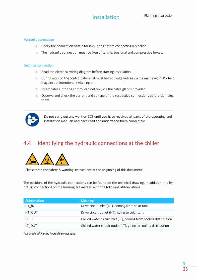
4.4 Identifying the hydraulic connections at the chiller
Please note the safety & warning instructions at the beginning of this document!
The positions of the hydraulic connections can be found on the technical drawing. In addition, the hy-draulic connections on the housing are marked with the following abbreviations:
Abbreviation Meaning
HT_IN Drive circuit inlet (HT), coming from solar tank
HT_OUT Drive circuit outlet (HT), going to solar tank
LT_IN Chilled water circuit inlet (LT), coming from cooling distribution
LT_OUT Chilled water circuit outlet (LT), going to cooling distribution
Tab. 3: Identifying the hydraulic connections
Planning Instruction Installation
10 25
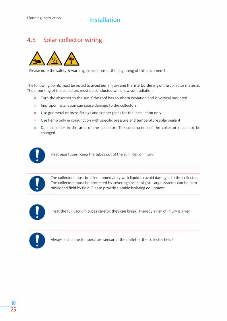
4.5 Solar collector wiring
Please note the safety & warning instructions at the beginning of this document!
The following points must be noted to avoid burn injury and thermal burdening of the collector material. The mounting of the collectors must be conducted while low sun radiation.
» Turn the absorber to the sun if the roof has southern deviation and is vertical mounted.
» Improper installation can cause damage to the collectors.
» Use gunmetal or brass fittings and copper pipes for the installation only.
» Use hemp only in conjunction with specific pressure and temperature solar sealant.
» Do not solder in the area of the collector! The construction of the collector must not be changed!
Heat pipe tubes: Keep the tubes out of the sun. Risk of injury!
The collectors must be filled immediately with liquid to avoid damages to the collector. The collectors must be protected by cover against sunlight. Large systems can be com-missioned field by field. Please provide suitable isolating equipment.
Treat the full vacuum tubes careful, they can break. Thereby a risk of injury is given.
Always install the temperature sensor at the outlet of the collector field!
Installation Planning Instruction
11 25
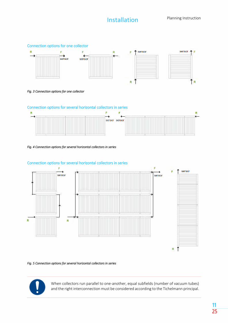
Connection options for one collector
Fig. 3 Connection options for one collector
Connection options for several horizontal collectors in series
Fig. 4 Connection options for several horizontal collectors in series
Connection options for several horizontal collectors in series
Fig. 5 Connection options for several horizontal collectors in series
When collectors run parallel to one-another, equal subfields (number of vacuum tubes) and the right interconnection must be considered according to the Tichelmann principal.

Planning Instruction Installation
12 25
4.6 Flow rate and pressure drop of solar field
Fig. 6 flow rate and pressure drop of solar field
Example
» Number of tubes: 80
» flow rate: 5,7 l/min
» pressure drop: 60 mbar
The system must be operated in order to avoid high temperatures and steam strokes even while stagnation. A maximum pressure of 1.5 bar in the collector layer must be set.
4.7 Marking on the electric connections
Please note the safety & warning instructions at the beginning of this document!
All power and control cables must be routed through the openings provided for this purpose to the control cabinet of SCS. The position of the cable entries can be seen in the wiring diagram.
0,0
1,0
2,0
3,0
4,0
5,0
6,0
7,0
8,0
9,0
10,0
11,0
20 40 60 80 100 120 140 160
0,0
1,0
2,0
3,0
4,0
5,0
6,0
7,0
8,0
9,0
10,0
11,0
050100150200250300350400450
number of tubes pressure drop [mbar]
flo
w r
ate
[l/m
in]
flo
w r
ate
[l/m
in]
Installation Planning Instruction
13 25
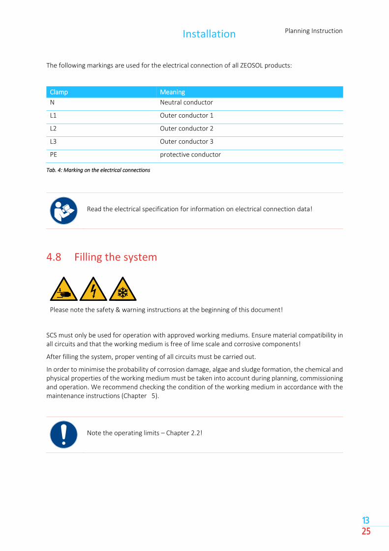
The following markings are used for the electrical connection of all ZEOSOL products:
Clamp Meaning
N Neutral conductor
L1 Outer conductor 1
L2 Outer conductor 2
L3 Outer conductor 3
PE protective conductor
Tab. 4: Marking on the electrical connections
Read the electrical specification for information on electrical connection data!
4.8 Filling the system
Please note the safety & warning instructions at the beginning of this document!
SCS must only be used for operation with approved working mediums. Ensure material compatibility in all circuits and that the working medium is free of lime scale and corrosive components!
After filling the system, proper venting of all circuits must be carried out.
In order to minimise the probability of corrosion damage, algae and sludge formation, the chemical and physical properties of the working medium must be taken into account during planning, commissioning and operation. We recommend checking the condition of the working medium in accordance with the maintenance instructions (Chapter 5).
Note the operating limits – Chapter 2.2!
Planning Instruction Installation
14 25
4.9 Permitted working mediums
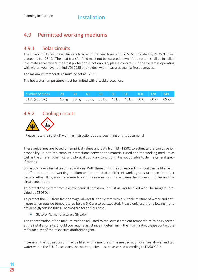
Solar circuits The solar circuit must be exclusively filled with the heat transfer fluid VT51 provided by ZEOSOL (frost protected to −28 °C). The heat transfer fluid must not be watered down. If the system shall be installed in climate zones where the frost protection is not enough, please contact us. If the system is operating with water, you have to mind VDI 2035 and to deal with measures against frost damages.
The maximum temperature must be set at 120 °C.
The hot water temperature must be limited with a scald protection.
number of tubes 20 30 40 50 60 80 100 120 140
VT51 (approx.) 15 kg 20 kg 30 kg 35 kg 40 kg 45 kg 50 kg 60 kg 65 kg
Cooling circuits
Please note the safety & warning instructions at the beginning of this document!
These guidelines are based on empirical values and data from EN-12502 to estimate the corrosive ion probability. Due to the complex interactions between the materials used and the working medium as well as the different chemical and physical boundary conditions, it is not possible to define general spec-ifications.
Some SCS have internal circuit separations. With these units, the corresponding circuit can be filled with a different permitted working medium and operated at a different working pressure than the other circuits. After filling, also make sure to vent the internal circuits between the process modules and the circuit separation.
To protect the system from electrochemical corrosion, it must always be filled with Thermogard, pro-vided by ZEOSOL!
To protect the SCS from frost damage, always fill the system with a suitable mixture of water and anti-freeze when outside temperatures below 5°C are to be expected. Please only use the following mono ethylene glycols including Thermogard for this purpose:
» Glysofor N, manufacturer: Glysofor
The concentration of the mixture must be adjusted to the lowest ambient temperature to be expected at the installation site. Should you require assistance in determining the mixing ratio, please contact the manufacturer of the respective antifreeze agent.
In general, the cooling circuit may be filled with a mixture of the needed additions (see above) and tap water within the EU. If necessary, the water quality must be assessed according to EN50930-6.
Installation Planning Instruction
15 25
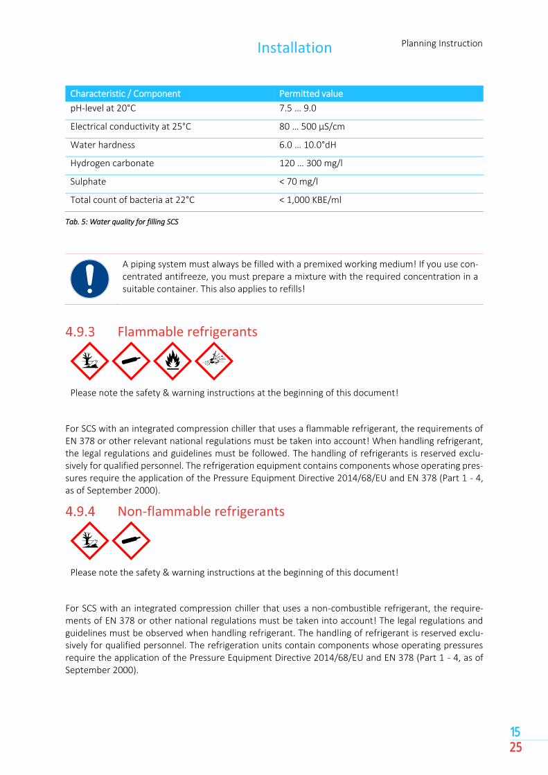
Characteristic / Component Permitted value
pH-level at 20°C 7.5 … 9.0
Electrical conductivity at 25°C 80 … 500 µS/cm
Water hardness 6.0 … 10.0°dH
Hydrogen carbonate 120 … 300 mg/l
Sulphate < 70 mg/l
Total count of bacteria at 22°C < 1,000 KBE/ml
Tab. 5: Water quality for filling SCS
A piping system must always be filled with a premixed working medium! If you use con-centrated antifreeze, you must prepare a mixture with the required concentration in a suitable container. This also applies to refills!
Flammable refrigerants
Please note the safety & warning instructions at the beginning of this document!
For SCS with an integrated compression chiller that uses a flammable refrigerant, the requirements of EN 378 or other relevant national regulations must be taken into account! When handling refrigerant, the legal regulations and guidelines must be followed. The handling of refrigerants is reserved exclu-sively for qualified personnel. The refrigeration equipment contains components whose operating pres-sures require the application of the Pressure Equipment Directive 2014/68/EU and EN 378 (Part 1 - 4, as of September 2000).
Non-flammable refrigerants
Please note the safety & warning instructions at the beginning of this document!
For SCS with an integrated compression chiller that uses a non-combustible refrigerant, the require-ments of EN 378 or other national regulations must be taken into account! The legal regulations and guidelines must be observed when handling refrigerant. The handling of refrigerant is reserved exclu-sively for qualified personnel. The refrigeration units contain components whose operating pressures require the application of the Pressure Equipment Directive 2014/68/EU and EN 378 (Part 1 - 4, as of September 2000).

Planning Instruction Inspection & Maintenance
16 25
5 Inspection & Maintenance
Please note the safety & warning instructions at the beginning of this document!
For a long-lasting and undisturbed operation of SCS, we recommend regular inspections and mainte-nance of the entire system. Maintenance work may only be carried out by qualified personnel. Below you will find an overview of the various stages for inspection and maintenance work as well as their intervals.
Inspection of the system Interval: every six months Execution: trained personnel
Measures:
» Visual inspection of the system for damaged insulation, leaks and defects in the electrical wiring
» Checking the operating pressure of all hydraulic circuits, if necessary a permitted working medium (chapter 4.9) must be refilled. Inform yourself which permitted working medium has been filled in the corresponding circuit
» Inspection of the fans of the re-cooler and cleaning of the heat exchanger block, especially on the suction side
» Function test of the pumps
» Read the last error message and take appropriate measures.
Maintenance of SCS Interval: annually Execution: certified personnel
Measures:
» Leakage and functional testing of all the valves and pumps of SCS and the circuit separation
» If necessary, update the software
» Checking all the set parameters
» Evaluation of error message
» General function test
Inspection & Maintenance Planning Instruction
17 25
» When a mixtures of water and mono ethylene glycols is used (Chapter 4.9), its concentra-tion is checked with a refractometer and if necessary, further measures are taken to exclude damage caused by frost
Maintenance of the Process Modules Interval: every 2 years Execution: certified personnel
Activities:
» Checking the vacuum stability of all process modules and restoring the vacuum if necessary
Special training and a service kit from ZEOSOL are required for maintenance of the pro-cess modules! Improper maintenance of the process module can lead to the destruction of the module!

Planning Instruction Decommissioning & Shutdown
18 25
6 Decommissioning & Shutdown
Please note the safety & warning instructions at the beginning of this document!
If SCS is to be left out of operation for an indefinite period of time, a proper shutdown of the system is recommended in order to avoid damage. Before you carry out any further work, SCS must be switched off and de-energised.
When dismounting a solar system or exchange a tube, the tubes must be emptied and kept out of the sun. Fluid rests in the system can lead to sudden steam strokes. Risk of injury!
During decommissioning, the storage and installation conditions must be followed (Chapter 8)
If the storage location differs from the installation location after decommissioning, please observe the instructions for transporting an adsorption chiller (Chapter 9)!
Recommissioning Planning Instruction
19 25
7 Recommissioning
Please note the safety & warning instructions at the beginning of this document!
After decommissioning, the system must be recommissioned to ensure proper and trouble-free opera-tion. For this purpose, all steps of the commissioning must be carried out by a certified service techni-cian.

Planning Instruction Storage & installation conditions
20 25
8 Storage & installation conditions
Please note the safety & warning instructions at the beginning of this document!
Make sure that the following storage & installation conditions are maintained at all times:
» The installation/storage should be reachable and easily accessible for transport using tech-nical aids
» Installation/storage of the chiller must be on a flat horizontal surface with a maximum in-clination of 2°; if necessary, a balance must be created with suitable supports
» The bearing capacity of the installation/storage area must be at least 1,000 kg/m²
» For the controller a condensation-free atmosphere is required for installation/storage
» Before storage, all hydraulic connections must be drained with a suitable wet aspirator
» For storage, SCS must be wrapped with a protective film
» When dismounting a solar system or exchange a tube, the tubes must be emptied and kept out of the sun
» For mounting at the installation site, the operating, maintenance and installation distances must be followed.
» The installation/storage of SCS with compression chillers must be carried out in accordance with the requirements of EN 378. Sufficient room space and ventilation measures are re-quired to protect persons.
In case of improper installation or storage, the warranty becomes void!

Transport of an solar cooling system
Planning Instruction
21 25
9 Transport of an solar cooling system
Please note the safety & warning instructions at the beginning of this document!
Please note the following points when transporting SCS:
» Use adequate and suitable protection during transport
» Pay attention to the balance point of the machine to avoid overturning
» Use only approved technical aids for transport
» Extreme care must be taken during transport
» To protect the housing, it must be wrapped with protective film during transport.
» Avoid shocks or impacts to chiller or solar tubes
» Do not tilt chiller over an angle of 40° and transport it as upright as possible
» The storage and installation conditions (Chapter 8) must also be complied with during transport.
» Installations with a compression chiller whose refrigerant filling quantity is over 12 kg are subjected to the dangerous goods (UN 2857)
Planning Instruction Disassembly
22 25
10 Disassembly
10.1 Disconnecting electrical connections
Please note the safety & warning instructions at the beginning of this document!
Carry out the following steps before you start to disassemble the electrical connections:
» Shut the system down properly (Chapter 6)
» Disconnect the connecting cables from the power supply
» Disconnect all connection and control cables from SCS controller and carefully pull the cables out of the housing
10.2 Disconnecting hydraulic connections
Please note the safety & warning instructions at the beginning of this document!
Carry out the following steps before you start to disassemble the hydraulic connections:
» Shut the system down properly (Chapter 6)
» Close all the cut-off valves of SCS
» Depressurise all circuits
» Empty the circuits properly and in an environmentally friendly manner, following the instructions of the regional authorities responsible
» Disconnect the hydraulic connections of SCS and intercept any leaking working medium with a suitable wet vacuum extractor
» Empty the hydraulic system of SCS with a suitable wet vacuum extractor
» Close the connections to protect them from contamination
» When dismounting solar tubes fluid rests in the system can lead to sudden steam strokes

Disposal Planning Instruction
23 25
11 Disposal
When disposing of SCS and/or its packaging materials, the environmentally relevant requirements for the recycling, reuse and disposal of operating materials and components must be complied with. The responsibility for the proper disposal of no longer usable operating materials and system components lies with the operator of the system.
Before disposing of SCS, it must be properly dismantled (Chapter 10) and the process modules vented! All materials must be disposed of in accordance with local and current regulations. Recycling centres or other suitable collection points can be requested from the respective municipal administration. The following requirements for the disposal of all materials must be followed.
Element Material Type of disposal
Pipes and housing Copper, steel Scrap metal
Electronics Mix of many materials Electronic waste
Process modules Copper, Aluminum, steel, Adsorbents
Take back and disposal by ZEOSOL
Packaging Cardboard, paper, foiled Paper container, composites
Tab. 6: Disposal of materials
Dispose of all materials and working fluids with additives (e.g. mono ethylene glycol) in accordance with local guidelines. Consult your local municipal administration for suitable recycling centres and collection point.

Planning Instruction Appendix
24 25
12 Appendix
12.1 commissioning checklist
Requirements for successful commissioning:
» For assembly, storage and installation, the planning instruction has been observed.
» The hydraulic installation of all circuits was completed and checked for leaks.
» The electrical installation has been completed.
» The system was flushed, filled with required mixtures and vented. The operating pressure is at least 1.5 bar.
» Voltage is present at chiller and solar system.
» The entire plant is in a ready-to-operate condition.
» The solar buffer is heated up for a test drive.
» A technician is present for commissioning, who can answer questions about hydraulics, electrics and ICA.
The operator assures the ZEOSOL service technician(s) that the solar cooling system is ready for opera-tion:
» Unhindered access to the rooms in which equipment and auxiliary facilities are located.
» Availability of all documentation and project documents belonging to the plant.
» Notes for customer-specific areas of responsibility (occupational safety, hygiene, ...).
NOTE
If, for reasons beyond ZEOSOL’s control, proper commissioning of the system is not possible, the oper-ator must bear any additional costs incurred. These will be charged to him separately!

The information about commissioning (12.1 commissioning checklist of planning instruction) has been noted and observed!
location, date sign
commissioning checklist
cust
om
er commissioning planned on
location of installation
contact person
phone number
chill
er place of installation
required chilled water temperature
others
ICA
external control YES / NO If yes, which:
external access required YES / NO
sola
r in
stal
lati
on
pump type
volume flow sensor or heat flow meter YES /NO If yes, type:
number of solar tubes
piping dimension: length:
coo
ling
circ
uit
external pump YES /NO If yes, pump type:
volume flow sensor or heat flow meter YES /NO If yes, type:
type of cooling (fan coil, cooling ceiling, process cooling, ...)
buffer storage available YES / NO If yes, with tempera-ture sensor for chiller: YES / NO
piping dimension: length:

www.zeosol.eu