Embed Size (px)
Citation preview

Planning Fundamentals
COOL-FIT 2.0
GF Piping Systems
08.2017 1
COOL-FIT 2.0 / COOL-FIT 2.0M
1 General Information ................................................................................................................... 2
2 System Specification ................................................................................................................. 3
3 Technical Details ........................................................................................................................ 5
3.1 COOL-FIT 2.0 ...................................................................................................................... 5
3.2 COOL-FIT 2.0M ..................................................................................................................12
3.3 COOL-FIT Tools .................................................................................................................13
4 Dimensioning and Design ........................................................................................................14
4.1 General information about the dimensioning and installation of plastic piping .....................14
4.2 COOL-FIT 2.0 pressure-temperature diagram ....................................................................14
4.3 Polyethylene (PE) ...............................................................................................................17
4.4 Fire behavior and fire prevention measures ........................................................................18
4.5 Hydraulic design .................................................................................................................20
4.6 Nomogram for easy calculation of diameter and pressure loss ...........................................22
4.7 Pressure loss ......................................................................................................................23
4.8 Dimension comparison COOL-FIT 2.0 / 2.0M metal ............................................................27
4.9 Z-dimension method ...........................................................................................................27
4.10 Length changes and flexible sections .................................................................................30
4.11 Installation ..........................................................................................................................33
4.12 Pipe bracket spacing and support of pipelines ....................................................................34
4.13 Hoses .................................................................................................................................38
4.14 COOL-FIT Calculation Tool ................................................................................................39
5 Jointing and Installation ...........................................................................................................41
5.1 Jointing of COOL-FIT 2.0/2.0M ...........................................................................................41
5.2 Installation of fixed points ....................................................................................................51
5.3 Pressure test ......................................................................................................................52
5.4 Internal pressure and leak testing .......................................................................................52
5.5 Start-up with secondary coolants ........................................................................................55
6 Transport, Handling and Storage .............................................................................................56
6.1 Transport ............................................................................................................................56
6.2 Storage ...............................................................................................................................56
6.3 Environment .......................................................................................................................56
COOL-FIT 2.0 / COOL-FIT 2.0M General Information
2 08.2017
1 General Information
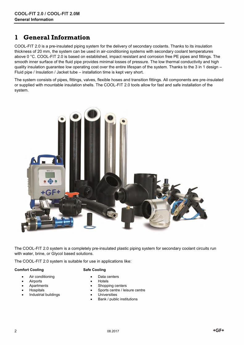
COOL-FIT 2.0 is a pre-insulated piping system for the delivery of secondary coolants. Thanks to its insulation thickness of 20 mm, the system can be used in air-conditioning systems with secondary coolant temperatures above 0 °C. COOL-FIT 2.0 is based on established, impact resistant and corrosion free PE pipes and fittings. The smooth inner surface of the fluid pipe provides minimal losses of pressure. The low thermal conductivity and high quality insulation guarantee low operating cost over the entire lifespan of the system. Thanks to the 3 in 1 design – Fluid pipe / Insulation / Jacket tube – installation time is kept very short.
The system consists of pipes, fittings, valves, flexible hoses and transition fittings. All components are pre-insulated or supplied with mountable insulation shells. The COOL-FIT 2.0 tools allow for fast and safe installation of the system.
The COOL-FIT 2.0 system is a completely pre-insulated plastic piping system for secondary coolant circuits run with water, brine, or Glycol based solutions.
The COOL-FIT 2.0 system is suitable for use in applications like:
Comfort Cooling Safe Cooling
Air conditioning Airports Apartments Hospitals Industrial buildings
Data centers Hotels Shopping centers Sports centre / leisure centre Universities Bank / public institutions
COOL-FIT 2.0 / COOL-FIT 2.0M System Specification
08.2017 3
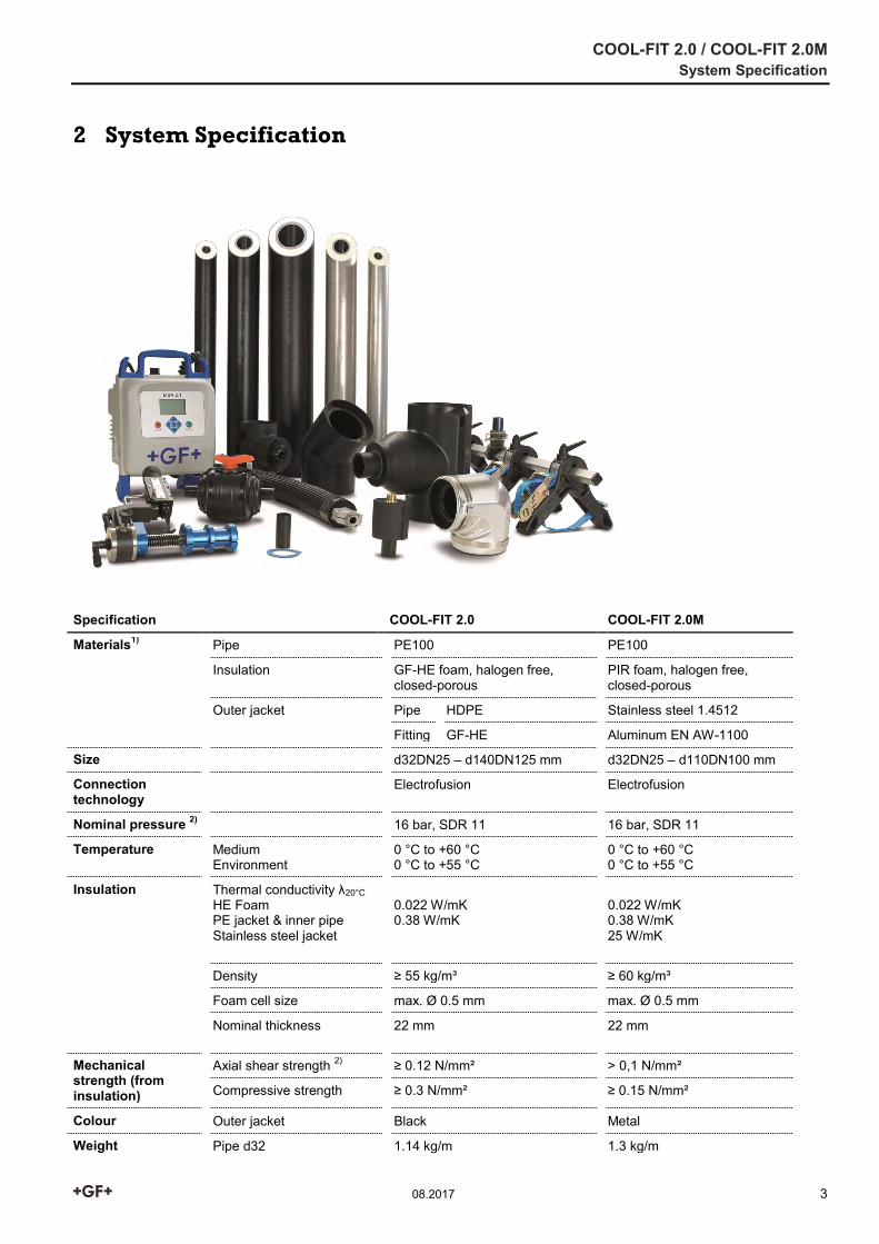
2 System Specification
Specification COOL-FIT 2.0 COOL-FIT 2.0M
Materials1) Pipe PE100 PE100
Insulation GF-HE foam, halogen free, closed-porous
PIR foam, halogen free, closed-porous
Outer jacket Pipe HDPE Stainless steel 1.4512
Fitting GF-HE Aluminum EN AW-1100
Size d32DN25 – d140DN125 mm d32DN25 – d110DN100 mm
Connection technology
Electrofusion Electrofusion
Nominal pressure 2) 16 bar, SDR 11 16 bar, SDR 11
Temperature Medium Environment
0 °C to +60 °C 0 °C to +55 °C
0 °C to +60 °C 0 °C to +55 °C
Insulation Thermal conductivity λ20°C HE Foam PE jacket & inner pipe Stainless steel jacket
0.022 W/mK 0.38 W/mK
0.022 W/mK 0.38 W/mK 25 W/mK
Density ≥ 55 kg/m³ ≥ 60 kg/m³
Foam cell size max. Ø 0.5 mm max. Ø 0.5 mm
Nominal thickness 22 mm
22 mm
Mechanical strength (from insulation)
Axial shear strength 2) ≥ 0.12 N/mm² > 0,1 N/mm²
Compressive strength ≥ 0.3 N/mm² ≥ 0.15 N/mm²
Colour Outer jacket Black Metal
Weight Pipe d32 1.14 kg/m 1.3 kg/m
COOL-FIT 2.0 / COOL-FIT 2.0M System Specification
4 08.2017
Specification COOL-FIT 2.0 COOL-FIT 2.0M
(without medium) Pipe d110 5.6 kg/m 5.7 kg/m
Oxygen diffusion at ≤ 20° C
DIN 53380 ≤ 0.31 mg/(m² d) 0 mg/(m² d) 3)
Fire classification Normal combustibility Low combustibility
Environment Stability Moisture and vapor-tight Moisture and vapor-tight
Ozone Depletion Potential Zero Zero
Standards and Guidelines
EN ISO 15494 Plastic piping systems for industrial applications – polybutene (PB), polyethylene (PE) and polypropylene (PP) – specifications for components and the piping system – metric series
ISO 7 Threaded Joints
EN ISO 16135 EN ISO 16136 EN ISO 16137 EN ISO 16138
Industrial valves – Ball valves made of thermoplastics Industrial valves – Butterfly valves made of thermoplastics Industrial valves – Backflow protection made of thermoplastics Industrial valves – Diaphragm valve made of thermoplastics
EN ISO 16871 Plastic piping and ducting systems – Plastic pipes and fittings – Method for exposure to direct (natural) weathering
1) All three materials are firmly bonded together. 2) At 20 ° C, medium water, the specified value is valid for all system components, with the exception of the butterfly valves, PN10 applies to the nominal pressure. 3) Pipe with a closed metal outer jacket
COOL-FIT 2.0 / COOL-FIT 2.0M Technical Details
08.2017 5
3 Technical Details
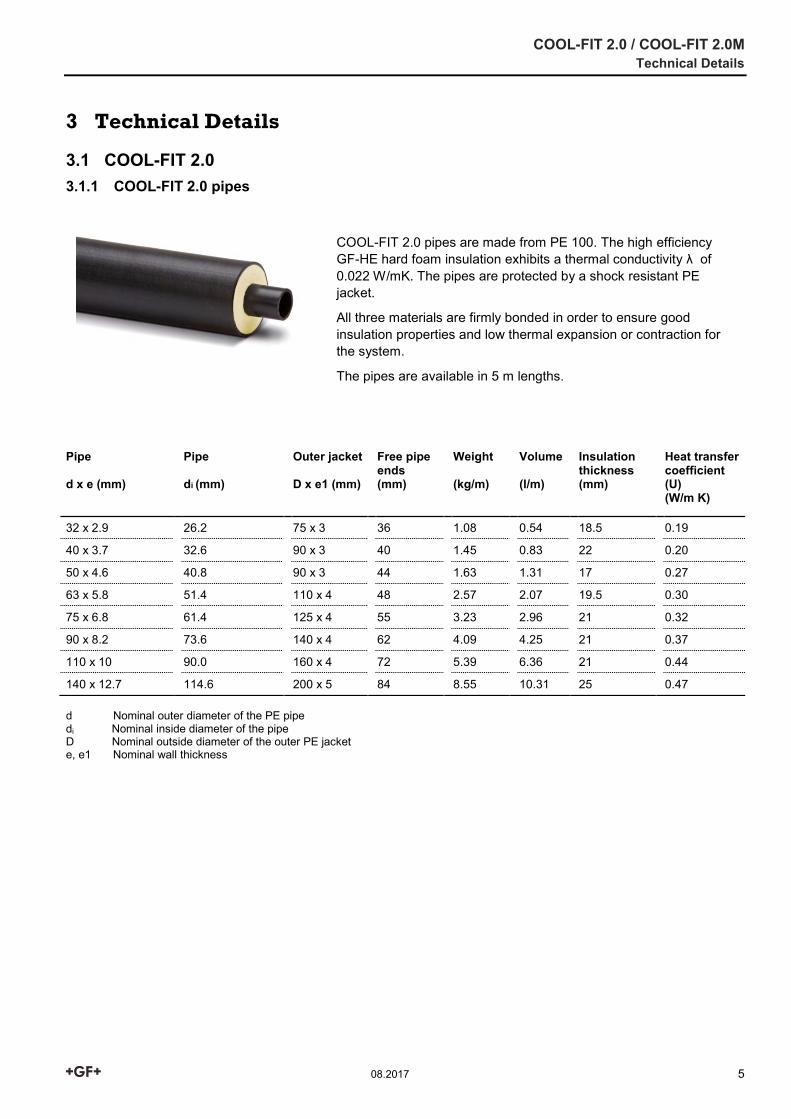
3.1 COOL-FIT 2.0 3.1.1 COOL-FIT 2.0 pipes
d Nominal outer diameter of the PE pipe di Nominal inside diameter of the pipe D Nominal outside diameter of the outer PE jacket e, e1 Nominal wall thickness
COOL-FIT 2.0 pipes are made from PE 100. The high efficiency GF-HE hard foam insulation exhibits a thermal conductivity λ of 0.022 W/mK. The pipes are protected by a shock resistant PE jacket.
All three materials are firmly bonded in order to ensure good insulation properties and low thermal expansion or contraction for the system.
The pipes are available in 5 m lengths.
Pipe d x e (mm)
Pipe di (mm)
Outer jacket D x e1 (mm)
Free pipe ends (mm)
Weight (kg/m)
Volume (l/m)
Insulation thickness (mm)
Heat transfer coefficient (U) (W/m K)
32 x 2.9 26.2 75 x 3 36 1.08 0.54 18.5 0.19
40 x 3.7 32.6 90 x 3 40 1.45 0.83 22 0.20
50 x 4.6 40.8 90 x 3 44 1.63 1.31 17 0.27
63 x 5.8 51.4 110 x 4 48 2.57 2.07 19.5 0.30
75 x 6.8 61.4 125 x 4 55 3.23 2.96 21 0.32
90 x 8.2 73.6 140 x 4 62 4.09 4.25 21 0.37
110 x 10 90.0 160 x 4 72 5.39 6.36 21 0.44
140 x 12.7 114.6 200 x 5 84 8.55 10.31 25 0.47
COOL-FIT 2.0 / COOL-FIT 2.0M Technical Details
6 08.2017
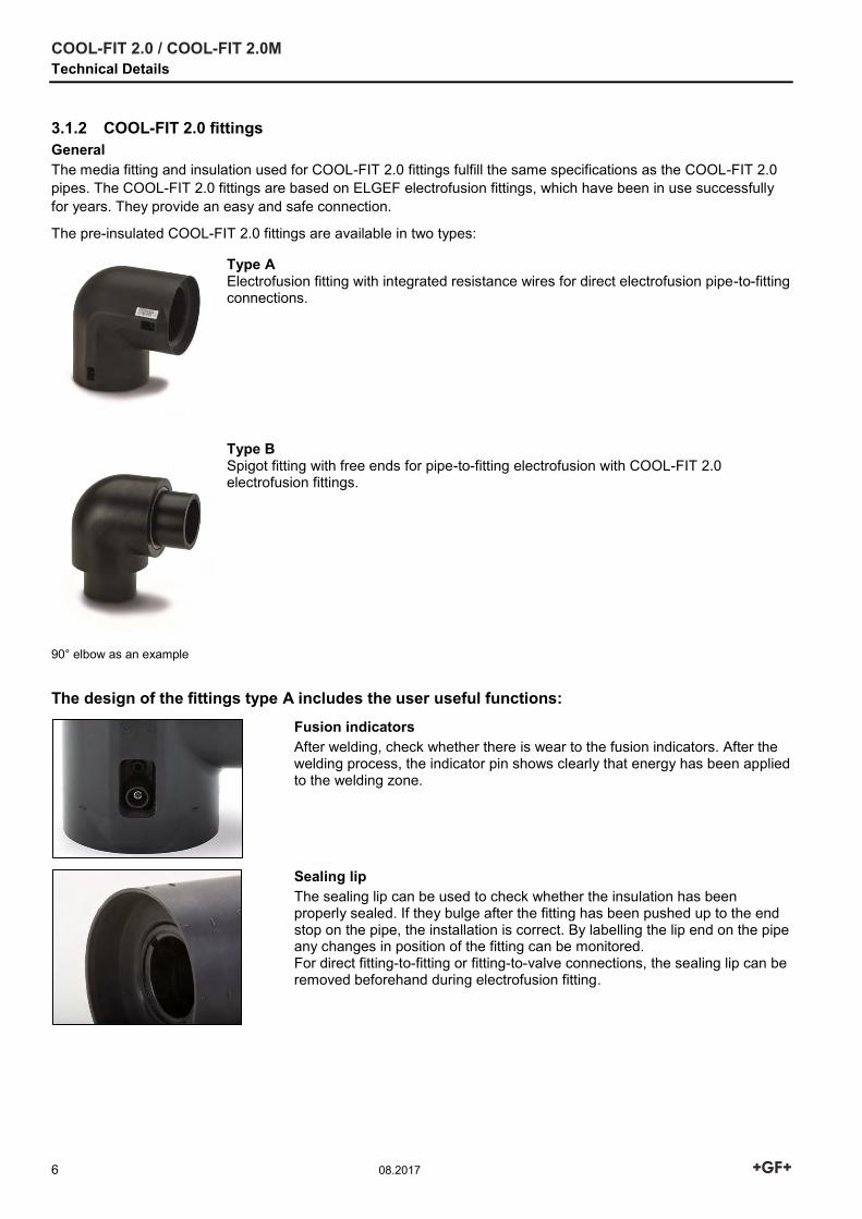
3.1.2 COOL-FIT 2.0 fittings General The media fitting and insulation used for COOL-FIT 2.0 fittings fulfill the same specifications as the COOL-FIT 2.0 pipes. The COOL-FIT 2.0 fittings are based on ELGEF electrofusion fittings, which have been in use successfully for years. They provide an easy and safe connection.
The pre-insulated COOL-FIT 2.0 fittings are available in two types:
Type A Electrofusion fitting with integrated resistance wires for direct electrofusion pipe-to-fitting connections.
90° elbow as an example
Type B Spigot fitting with free ends for pipe-to-fitting electrofusion with COOL-FIT 2.0 electrofusion fittings.
The design of the fittings type A includes the user useful functions:
Fusion indicators After welding, check whether there is wear to the fusion indicators. After the welding process, the indicator pin shows clearly that energy has been applied to the welding zone.
Sealing lip The sealing lip can be used to check whether the insulation has been properly sealed. If they bulge after the fitting has been pushed up to the end stop on the pipe, the installation is correct. By labelling the lip end on the pipe any changes in position of the fitting can be monitored. For direct fitting-to-fitting or fitting-to-valve connections, the sealing lip can be removed beforehand during electrofusion fitting.
COOL-FIT 2.0 / COOL-FIT 2.0M Technical Details
08.2017 7
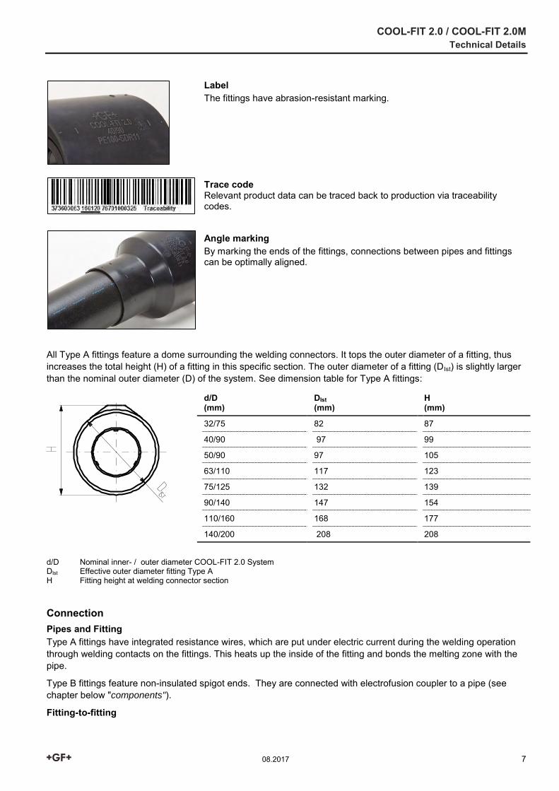
Label The fittings have abrasion-resistant marking. Trace code Relevant product data can be traced back to production via traceability codes.
Angle marking By marking the ends of the fittings, connections between pipes and fittings can be optimally aligned.
All Type A fittings feature a dome surrounding the welding connectors. It tops the outer diameter of a fitting, thus increases the total height (H) of a fitting in this specific section. The outer diameter of a fitting (DIst) is slightly larger than the nominal outer diameter (D) of the system. See dimension table for Type A fittings:
d/D (mm)
DIst (mm)
H (mm)
32/75 82 87
40/90 97 99
50/90 97 105
63/110 117 123
75/125 132 139
90/140 147 154
110/160 168 177
140/200 208 208
d/D Nominal inner- / outer diameter COOL-FIT 2.0 System DIst Effective outer diameter fitting Type A H Fitting height at welding connector section
Connection Pipes and Fitting Type A fittings have integrated resistance wires, which are put under electric current during the welding operation through welding contacts on the fittings. This heats up the inside of the fitting and bonds the melting zone with the pipe.
Type B fittings feature non-insulated spigot ends. They are connected with electrofusion coupler to a pipe (see chapter below "components").
Fitting-to-fitting
COOL-FIT 2.0 / COOL-FIT 2.0M Technical Details
8 08.2017
Two COOL-FIT 2.0 fittings are usually connected by using a piece of COOL-FIT 2.0 pipe with free ends or a short piece of ecoFIT PE pipe and an insulation ring (e.g. ring removed with the foam removal tool). The shortest connection between two COOL-FIT 2.0 Type A fittings can be achieved by cutting off the sealing lips and using a double nipple and an adhesive ring for the vapor seal (see components).
Two COOL-FIT 2.0 Type B fittings can be joined using an electrofusion coupler (see components).
The connection of a COOL-FIT 2.0 fitting Type A and Type B is also possible.
Components
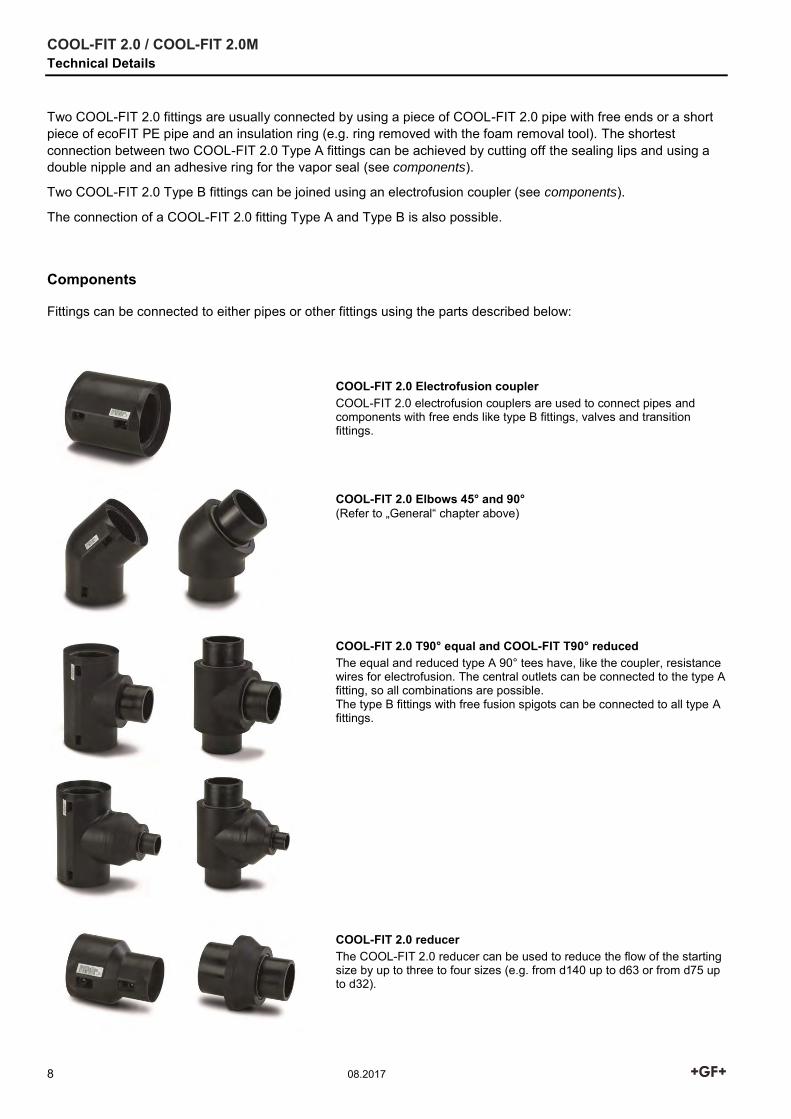
Fittings can be connected to either pipes or other fittings using the parts described below:
COOL-FIT 2.0 Electrofusion coupler COOL-FIT 2.0 electrofusion couplers are used to connect pipes and components with free ends like type B fittings, valves and transition fittings. COOL-FIT 2.0 Elbows 45° and 90° (Refer to „General“ chapter above)
COOL-FIT 2.0 T90° equal and COOL-FIT T90° reduced The equal and reduced type A 90° tees have, like the coupler, resistance wires for electrofusion. The central outlets can be connected to the type A fitting, so all combinations are possible. The type B fittings with free fusion spigots can be connected to all type A fittings.
COOL-FIT 2.0 reducer The COOL-FIT 2.0 reducer can be used to reduce the flow of the starting size by up to three to four sizes (e.g. from d140 up to d63 or from d75 up to d32).
COOL-FIT 2.0 / COOL-FIT 2.0M Technical Details
08.2017 9
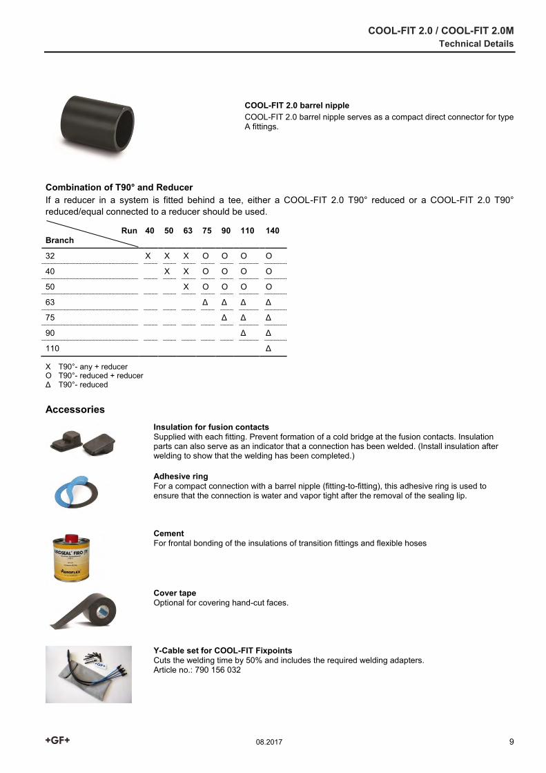
COOL-FIT 2.0 barrel nipple COOL-FIT 2.0 barrel nipple serves as a compact direct connector for type A fittings.
Combination of T90° and Reducer If a reducer in a system is fitted behind a tee, either a COOL-FIT 2.0 T90° reduced or a COOL-FIT 2.0 T90° reduced/equal connected to a reducer should be used.
Run Branch
40 50 63 75 90 110 140
32 X X X O O O O
40 X X O O O O
50 X O O O O
63 Δ Δ Δ Δ
75 Δ Δ Δ
90 Δ Δ
110 Δ
X T90°- any + reducer O T90°- reduced + reducer Δ T90°- reduced
Accessories
Insulation for fusion contacts Supplied with each fitting. Prevent formation of a cold bridge at the fusion contacts. Insulation parts can also serve as an indicator that a connection has been welded. (Install insulation after welding to show that the welding has been completed.)
Adhesive ring For a compact connection with a barrel nipple (fitting-to-fitting), this adhesive ring is used to ensure that the connection is water and vapor tight after the removal of the sealing lip. Cement For frontal bonding of the insulations of transition fittings and flexible hoses
Cover tape Optional for covering hand-cut faces.
Y-Cable set for COOL-FIT Fixpoints Cuts the welding time by 50% and includes the required welding adapters. Article no.: 790 156 032
COOL-FIT 2.0 / COOL-FIT 2.0M Technical Details
10 08.2017
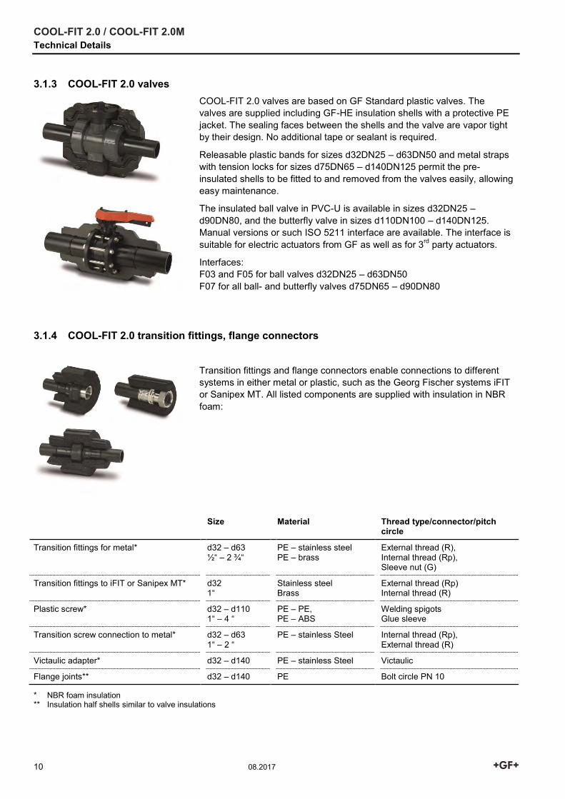
3.1.3 COOL-FIT 2.0 valves
COOL-FIT 2.0 valves are based on GF Standard plastic valves. The valves are supplied including GF-HE insulation shells with a protective PE jacket. The sealing faces between the shells and the valve are vapor tight by their design. No additional tape or sealant is required.
Releasable plastic bands for sizes d32DN25 – d63DN50 and metal straps with tension locks for sizes d75DN65 – d140DN125 permit the pre-insulated shells to be fitted to and removed from the valves easily, allowing easy maintenance.
The insulated ball valve in PVC-U is available in sizes d32DN25 – d90DN80, and the butterfly valve in sizes d110DN100 – d140DN125. Manual versions or such ISO 5211 interface are available. The interface is suitable for electric actuators from GF as well as for 3rd party actuators.
Interfaces: F03 and F05 for ball valves d32DN25 – d63DN50 F07 for all ball- and butterfly valves d75DN65 – d90DN80
3.1.4 COOL-FIT 2.0 transition fittings, flange connectors
Transition fittings and flange connectors enable connections to different systems in either metal or plastic, such as the Georg Fischer systems iFIT or Sanipex MT. All listed components are supplied with insulation in NBR foam:
Size Material Thread type/connector/pitch circle
Transition fittings for metal* d32 – d63 ½“ – 2 ¾“
PE – stainless steel PE – brass
External thread (R), Internal thread (Rp), Sleeve nut (G)
Transition fittings to iFIT or Sanipex MT* d32 1“
Stainless steel Brass
External thread (Rp) Internal thread (R)
Plastic screw* d32 – d110 1“ – 4 “
PE – PE, PE – ABS
Welding spigots Glue sleeve
Transition screw connection to metal* d32 – d63 1“ – 2 “
PE – stainless Steel
Internal thread (Rp), External thread (R)
Victaulic adapter* d32 – d140 PE – stainless Steel Victaulic
Flange joints** d32 – d140 PE Bolt circle PN 10
* NBR foam insulation ** Insulation half shells similar to valve insulations
COOL-FIT 2.0 / COOL-FIT 2.0M Technical Details
08.2017 11
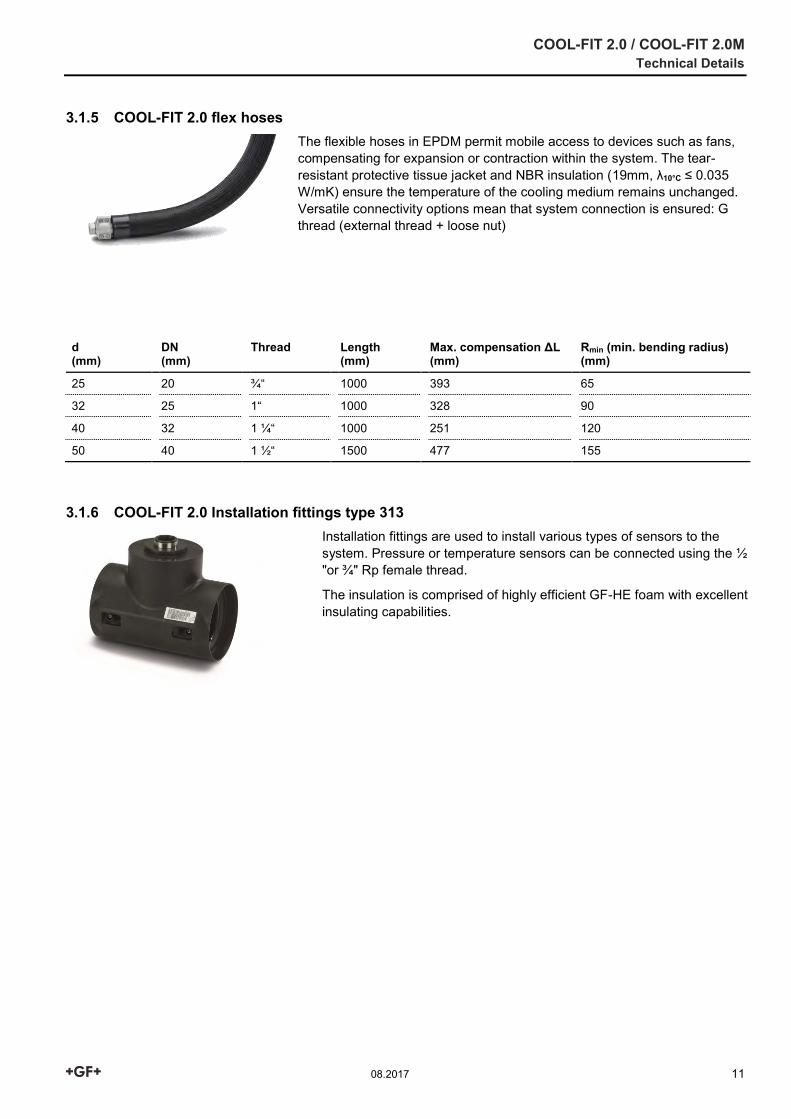
3.1.5 COOL-FIT 2.0 flex hoses
The flexible hoses in EPDM permit mobile access to devices such as fans, compensating for expansion or contraction within the system. The tear-resistant protective tissue jacket and NBR insulation (19mm, λ10°C ≤ 0.035 W/mK) ensure the temperature of the cooling medium remains unchanged. Versatile connectivity options mean that system connection is ensured: G thread (external thread + loose nut)
d (mm)
DN (mm)
Thread
Length (mm)
Max. compensation ΔL (mm)
Rmin (min. bending radius) (mm)
25 20 ¾“ 1000 393 65
32 25 1“ 1000 328 90
40 32 1 ¼“ 1000 251 120
50 40 1 ½“ 1500 477 155
3.1.6 COOL-FIT 2.0 Installation fittings type 313
Installation fittings are used to install various types of sensors to the system. Pressure or temperature sensors can be connected using the ½ "or ¾" Rp female thread.
The insulation is comprised of highly efficient GF-HE foam with excellent insulating capabilities.
COOL-FIT 2.0 / COOL-FIT 2.0M Technical Details
12 08.2017
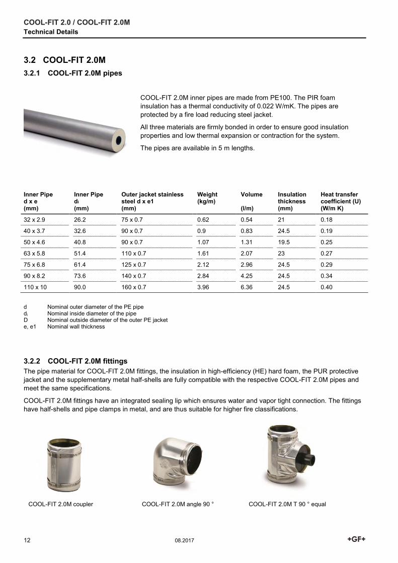
3.2 COOL-FIT 2.0M 3.2.1 COOL-FIT 2.0M pipes
COOL-FIT 2.0M inner pipes are made from PE100. The PIR foam insulation has a thermal conductivity of 0.022 W/mK. The pipes are protected by a fire load reducing steel jacket.
All three materials are firmly bonded in order to ensure good insulation properties and low thermal expansion or contraction for the system.
The pipes are available in 5 m lengths.
d Nominal outer diameter of the PE pipe di Nominal inside diameter of the pipe D Nominal outside diameter of the outer PE jacket e, e1 Nominal wall thickness
3.2.2 COOL-FIT 2.0M fittings The pipe material for COOL-FIT 2.0M fittings, the insulation in high-efficiency (HE) hard foam, the PUR protective jacket and the supplementary metal half-shells are fully compatible with the respective COOL-FIT 2.0M pipes and meet the same specifications.
COOL-FIT 2.0M fittings have an integrated sealing lip which ensures water and vapor tight connection. The fittings have half-shells and pipe clamps in metal, and are thus suitable for higher fire classifications.
Inner Pipe d x e (mm)
Inner Pipe di (mm)
Outer jacket stainless steel d x e1 (mm)
Weight (kg/m)
Volume (l/m)
Insulation thickness (mm)
Heat transfer coefficient (U) (W/m K)
32 x 2.9 26.2 75 x 0.7 0.62 0.54 21 0.18
40 x 3.7 32.6 90 x 0.7 0.9 0.83 24.5 0.19
50 x 4.6 40.8 90 x 0.7 1.07 1.31 19.5 0.25
63 x 5.8 51.4 110 x 0.7 1.61 2.07 23 0.27
75 x 6.8 61.4 125 x 0.7 2.12 2.96 24.5 0.29
90 x 8.2 73.6 140 x 0.7 2.84 4.25 24.5 0.34
110 x 10 90.0 160 x 0.7 3.96 6.36 24.5 0.40
COOL-FIT 2.0M coupler COOL-FIT 2.0M angle 90 ° COOL-FIT 2.0M T 90 ° equal
COOL-FIT 2.0 / COOL-FIT 2.0M Technical Details
08.2017 13
3.3 COOL-FIT Tools
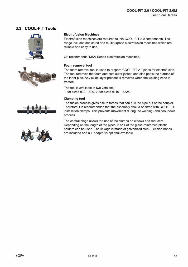
Electrofusion Machines Electrofusion machines are required to join COOL-FIT 2.0 components. The range includes dedicated and multipurpose electrofusion machines which are reliable and easy to use.
GF recommends: MSA-Series electrofusion machines.
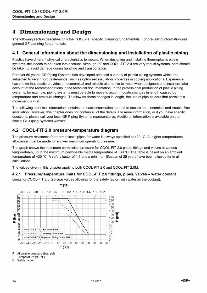
Foam removal tool The foam removal tool is used to prepare COOL-FIT 2.0 pipes for electrofusion. The tool removes the foam and cuts outer jacket, and also peels the surface of the inner pipe. Any oxide layer present is removed when the welding zone is treated.
The tool is available in two versions: 1. for sizes d32 – d90, 2. for sizes d110 – d225.
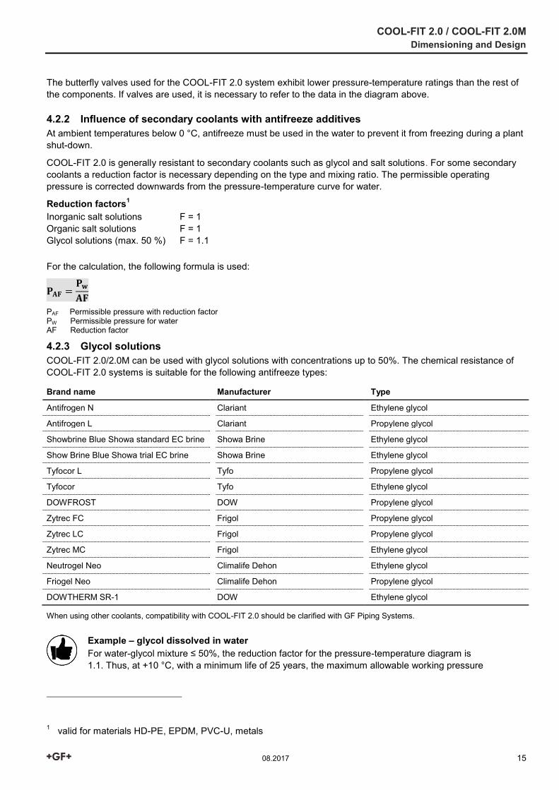
Clamping tool The fusion process gives rise to forces that can pull the pipe out of the coupler. Therefore it is recommended that the assembly should be fitted with COOL-FIT installation clamps. This prevents movement during the welding- and cool-down process.
The central hinge allows the use of the clamps on elbows and reducers. Depending on the length of the pipes, 2 or 4 of the glass-reinforced plastic holders can be used. The linkage is made of galvanized steel. Tension bands are included and a T-adapter is optional available.
COOL-FIT 2.0 / COOL-FIT 2.0M Dimensioning and Design
14 08.2017
4 Dimensioning and Design
The following section describes only the COOL-FIT specific planning fundamentals. For prevailing information see general GF planning fundamentals.
4.1 General information about the dimensioning and installation of plastic piping Plastics have different physical characteristics to metals. When designing and installing thermoplastic piping systems, this needs to be taken into account. Although PE and COOL-FIT 2.0 are very robust systems, care should be taken to avoid damage during handling and transportation.
For over 50 years, GF Piping Systems has developed and sold a variety of plastic piping systems which are subjected to very rigorous demands, such as optimized insulation properties in cooling applications. Experience has shown that plastic provides an economical and reliable alternative to metal when designers and installers take account of the recommendations in the technical documentation. In the professional production of plastic piping systems, for example, piping systems must be able to move to accommodate changes in length caused by temperature and pressure changes. To allow for these changes in length, the use of pipe holders that permit this movement is vital.
The following technical information contains the basic information needed to ensure an economical and trouble-free installation. However, this chapter does not contain all of the details. For more information, or if you have specific questions, please call your local GF Piping Systems representative. Additional information is available on the official GF Piping Systems website.
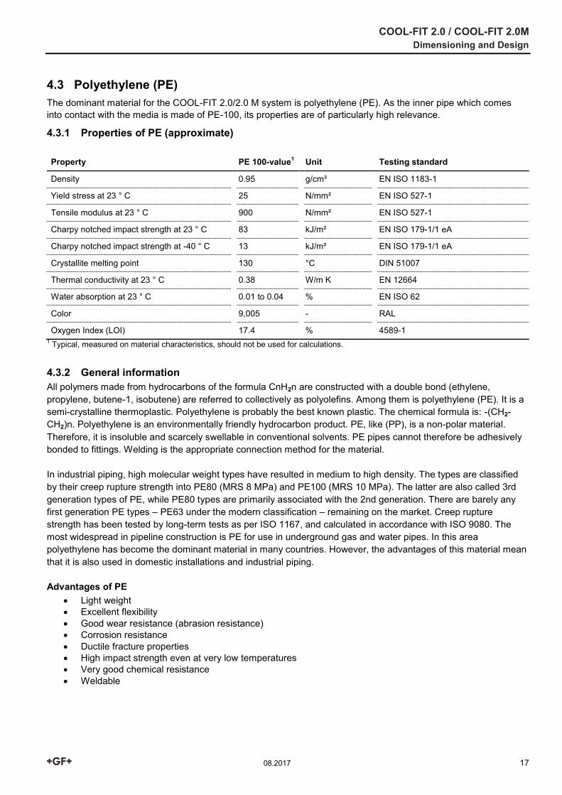
4.2 COOL-FIT 2.0 pressure-temperature diagram The pressure resistance for thermoplastic pipes for water is always specified at +20 °C. At higher temperatures allowance must be made for a lower maximum operating pressure.
The graph shows the maximum permissible pressure for COOL-FIT 2.0 pipes, fittings and valves at various temperatures, up to the maximum permissible media temperature of +60 °C. The table is based on an ambient temperature of +20 °C. A safety factor of 1.6 and a minimum lifespan of 25 years have been allowed for in all calculations.
The values given in this chapter apply to both COOL-FIT 2.0 and COOL-FIT 2.0M.
4.2.1 Pressure/temperature limits for COOL-FIT 2.0 fittings, pipes, valves – water coolant Limits for COOL-FIT 2.0: 25-year values allowing for the safety factor (with water as the coolant).
P Allowable pressure (bar, psi) T Temperature (°C, °F) C Safety factor
COOL-FIT 2.0 / COOL-FIT 2.0M Dimensioning and Design
08.2017 15
The butterfly valves used for the COOL-FIT 2.0 system exhibit lower pressure-temperature ratings than the rest of the components. If valves are used, it is necessary to refer to the data in the diagram above.
4.2.2 Influence of secondary coolants with antifreeze additives At ambient temperatures below 0 °C, antifreeze must be used in the water to prevent it from freezing during a plant shut-down.
COOL-FIT 2.0 is generally resistant to secondary coolants such as glycol and salt solutions. For some secondary coolants a reduction factor is necessary depending on the type and mixing ratio. The permissible operating pressure is corrected downwards from the pressure-temperature curve for water.
Reduction factors1 Inorganic salt solutions F = 1 Organic salt solutions F = 1 Glycol solutions (max. 50 %) F = 1.1
For the calculation, the following formula is used:
𝐏𝐀𝐅 =𝐏𝐰
𝐀𝐅
PAF Permissible pressure with reduction factor PW Permissible pressure for water AF Reduction factor
4.2.3 Glycol solutions COOL-FIT 2.0/2.0M can be used with glycol solutions with concentrations up to 50%. The chemical resistance of COOL-FIT 2.0 systems is suitable for the following antifreeze types:
Brand name Manufacturer Type
Antifrogen N Clariant Ethylene glycol
Antifrogen L Clariant Propylene glycol
Showbrine Blue Showa standard EC brine Showa Brine Ethylene glycol
Show Brine Blue Showa trial EC brine Showa Brine Ethylene glycol
Tyfocor L Tyfo Propylene glycol
Tyfocor Tyfo Ethylene glycol
DOWFROST DOW Propylene glycol
Zytrec FC Frigol Propylene glycol
Zytrec LC Frigol Propylene glycol
Zytrec MC Frigol Ethylene glycol
Neutrogel Neo Climalife Dehon Ethylene glycol
Friogel Neo Climalife Dehon Propylene glycol
DOWTHERM SR-1 DOW Ethylene glycol
When using other coolants, compatibility with COOL-FIT 2.0 should be clarified with GF Piping Systems.
Example – glycol dissolved in water For water-glycol mixture ≤ 50%, the reduction factor for the pressure-temperature diagram is 1.1. Thus, at +10 °C, with a minimum life of 25 years, the maximum allowable working pressure
1 valid for materials HD-PE, EPDM, PVC-U, metals

COOL-FIT 2.0 / COOL-FIT 2.0M Dimensioning and Design
16 08.2017
is reduced as follows:
𝐏𝐀𝐅 =𝟏𝟔 𝐛𝐚𝐫
𝟏. 𝟏= 𝟏𝟒. 𝟓 𝐛𝐚𝐫
4.2.4 Organic salt solutions These media are usually potassium formates or potassium acetates: aqueous solutions with low viscosity at low temperatures. COOL-FIT 2.0 can be used with the media below. The manufacturer's instructions must be followed.
Brand name Manufacturer Type
Antifrogen KF Clariant Brine
Zytrec S-55 Frigol Brine
Temper Temper Brine
Hycool Addcon Brine
For detailed information on resistance and reduction factors, see Planning Fundamentals "Material selection – Chemical resistance".
COOL-FIT 2.0 / COOL-FIT 2.0M Dimensioning and Design
08.2017 17
4.3 Polyethylene (PE) The dominant material for the COOL-FIT 2.0/2.0 M system is polyethylene (PE). As the inner pipe which comes into contact with the media is made of PE-100, its properties are of particularly high relevance.
4.3.1 Properties of PE (approximate)
Property PE 100-value1 Unit Testing standard
Density 0.95 g/cm³ EN ISO 1183-1
Yield stress at 23 ° C 25 N/mm² EN ISO 527-1
Tensile modulus at 23 ° C 900 N/mm² EN ISO 527-1
Charpy notched impact strength at 23 ° C 83 kJ/m² EN ISO 179-1/1 eA
Charpy notched impact strength at -40 ° C 13 kJ/m² EN ISO 179-1/1 eA
Crystallite melting point 130 °C DIN 51007
Thermal conductivity at 23 ° C 0.38 W/m K EN 12664
Water absorption at 23 ° C 0.01 to 0.04 % EN ISO 62
Color 9,005 - RAL
Oxygen Index (LOI) 17.4 % 4589-1 1 Typical, measured on material characteristics, should not be used for calculations.
4.3.2 General information All polymers made from hydrocarbons of the formula CnH2n are constructed with a double bond (ethylene, propylene, butene-1, isobutene) are referred to collectively as polyolefins. Among them is polyethylene (PE). It is a semi-crystalline thermoplastic. Polyethylene is probably the best known plastic. The chemical formula is: -(CH2-CH2)n. Polyethylene is an environmentally friendly hydrocarbon product. PE, like (PP), is a non-polar material. Therefore, it is insoluble and scarcely swellable in conventional solvents. PE pipes cannot therefore be adhesively bonded to fittings. Welding is the appropriate connection method for the material. In industrial piping, high molecular weight types have resulted in medium to high density. The types are classified by their creep rupture strength into PE80 (MRS 8 MPa) and PE100 (MRS 10 MPa). The latter are also called 3rd generation types of PE, while PE80 types are primarily associated with the 2nd generation. There are barely any first generation PE types – PE63 under the modern classification – remaining on the market. Creep rupture strength has been tested by long-term tests as per ISO 1167, and calculated in accordance with ISO 9080. The most widespread in pipeline construction is PE for use in underground gas and water pipes. In this area polyethylene has become the dominant material in many countries. However, the advantages of this material mean that it is also used in domestic installations and industrial piping. Advantages of PE
Light weight Excellent flexibility Good wear resistance (abrasion resistance) Corrosion resistance Ductile fracture properties High impact strength even at very low temperatures Very good chemical resistance Weldable
COOL-FIT 2.0 / COOL-FIT 2.0M Dimensioning and Design
18 08.2017
4.3.3 Mechanical properties, chemicals, weathering and abrasion resistance
Chemical resistance Polyethylene exhibits good resistance to a wide range of media. For detailed information, please see the detailed chemical resistance list from GF Piping Systems, or contact the person responsible at GF Piping Systems directly.
Abrasion resistance PE has excellent resistance to abrasive wear. You can therefore find PE piping systems in use in numerous applications for transporting solids and media containing solids. For many applications, PE has proven especially advantageous with metals.
4.3.4 Thermal properties, fire behaviour, electrical properties, physiological characteristics
Operating limits The application limits of the material depend on both embrittlement and softening temperatures and on the manner and method of application. Details are provided in the relevant pressure-temperature charts.
Electrical properties Polyethylene, like most thermoplastics, is non-conductive. This means that systems in PE do not suffer from electrolytic corrosion. However, the non-conductive properties must be taken into consideration, as electrostatic charges can build up in the pipe. Polyethylene has good electrical insulation properties. The volume resistance is 3.5 x 10¹⁶ Ωcm, the surface resistance 1013 Ω. This must be taken into account in applications where there is danger of fire or explosion.
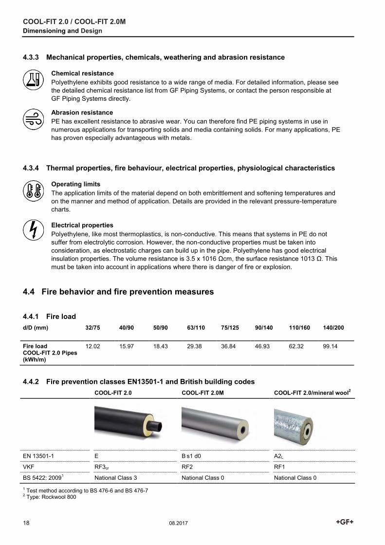
4.4 Fire behavior and fire prevention measures
4.4.1 Fire load d/D (mm) 32/75 40/90 50/90 63/110 75/125 90/140 110/160 140/200
Fire load COOL-FIT 2.0 Pipes (kWh/m)
12.02 15.97 18.43 29.38 36.84 46.93 62.32 99.14
4.4.2 Fire prevention classes EN13501-1 and British building codes COOL-FIT 2.0 COOL-FIT 2.0M COOL-FIT 2.0/mineral wool2
EN 13501-1 E B s1 d0 A2L
VKF RF3cr RF2 RF1
BS 5422: 20091 National Class 3 National Class 0 National Class 0
1 Test method according to BS 476-6 and BS 476-7 2 Type: Rockwool 800
COOL-FIT 2.0 / COOL-FIT 2.0M Dimensioning and Design
08.2017 19
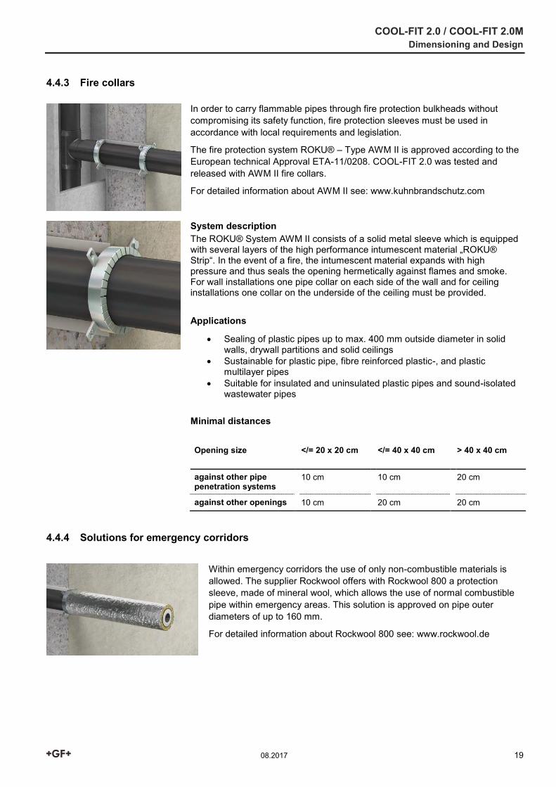
4.4.3 Fire collars
In order to carry flammable pipes through fire protection bulkheads without compromising its safety function, fire protection sleeves must be used in accordance with local requirements and legislation.
The fire protection system ROKU® – Type AWM II is approved according to the European technical Approval ETA-11/0208. COOL-FIT 2.0 was tested and released with AWM II fire collars.
For detailed information about AWM II see: www.kuhnbrandschutz.com
System description The ROKU® System AWM II consists of a solid metal sleeve which is equipped with several layers of the high performance intumescent material „ROKU® Strip“. In the event of a fire, the intumescent material expands with high pressure and thus seals the opening hermetically against flames and smoke. For wall installations one pipe collar on each side of the wall and for ceiling installations one collar on the underside of the ceiling must be provided.
Applications
Sealing of plastic pipes up to max. 400 mm outside diameter in solid walls, drywall partitions and solid ceilings
Sustainable for plastic pipe, fibre reinforced plastic-, and plastic multilayer pipes
Suitable for insulated and uninsulated plastic pipes and sound-isolated wastewater pipes
Minimal distances
Opening size </= 20 x 20 cm </= 40 x 40 cm > 40 x 40 cm
against other pipe penetration systems
10 cm 10 cm 20 cm
against other openings 10 cm 20 cm 20 cm
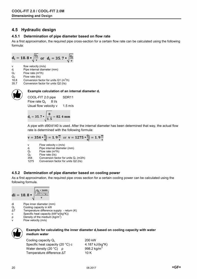
4.4.4 Solutions for emergency corridors
Within emergency corridors the use of only non-combustible materials is allowed. The supplier Rockwool offers with Rockwool 800 a protection sleeve, made of mineral wool, which allows the use of normal combustible pipe within emergency areas. This solution is approved on pipe outer diameters of up to 160 mm.
For detailed information about Rockwool 800 see: www.rockwool.de
COOL-FIT 2.0 / COOL-FIT 2.0M Dimensioning and Design
20 08.2017
4.5 Hydraulic design 4.5.1 Determination of pipe diameter based on flow rate As a first approximation, the required pipe cross-section for a certain flow rate can be calculated using the following formula:
𝐝𝐢 = 𝟏𝟖. 𝟖 √𝐐𝟏
𝐯 or 𝐝𝐢 = 𝟑𝟓. 𝟕 √
𝐐𝟐
𝐯
v flow velocity (m/s) di Pipe internal diameter (mm) Q1 Flow rate (m³/h) Q2 Flow rate (l/s) 18.8 Conversion factor for units Q1 (m3/h) 35.7 Conversion factor for units Q2 (l/s)
Example calculation of an internal diameter di
COOL-FIT 2.0 pipe SDR11 Flow rate Q2 8 l/s Usual flow velocity v 1.5 m/s
𝐝𝐢 = 𝟑𝟓. 𝟕 √𝟖
𝟏. 𝟓= 𝟖𝟐. 𝟒 𝐦𝐦
A pipe with d90/d140 is used. After the internal diameter has been determined that way, the actual flow rate is determined with the following formula:
𝐯 = 𝟑𝟓𝟒 𝐐𝟏
𝐝𝐢𝟐 = 𝟏. 𝟗
𝐦
𝐬 or 𝐯 = 𝟏𝟐𝟕𝟓
𝐐𝟐
𝐝𝐢𝟐 = 𝟏. 𝟗
𝐦
𝐬
v Flow velocity v (m/s) di Pipe internal diameter (mm) Q1 Flow rate (m³/h) Q2 Flow rate (l/s) 354 Conversion factor for units Q1 (m3/h) 1275 Conversion factor for units Q2 (l/s)
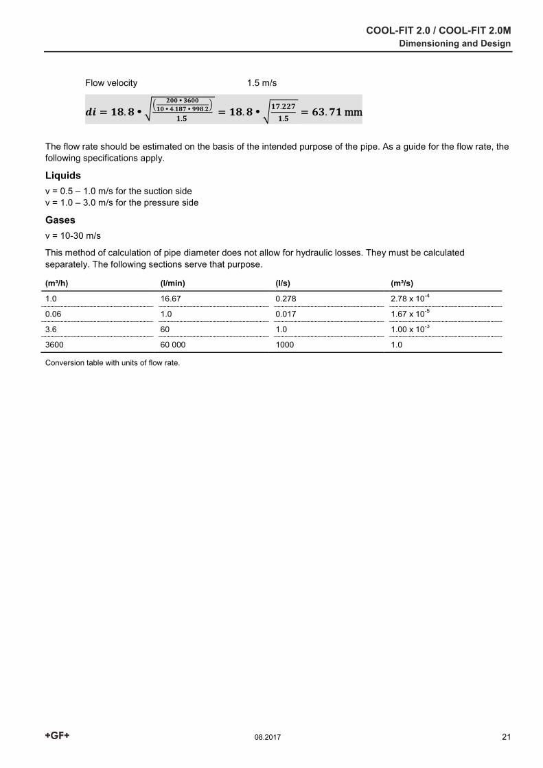
4.5.2 Determination of pipe diameter based on cooling power As a first approximation, the required pipe cross section for a certain cooling power can be calculated using the following formula.
𝐝𝐢 = 𝟏𝟖. 𝟖 √(
𝑸𝑳 𝟑𝟔𝟎𝟎
∆𝐓 с 𝛒)
𝐯
di Pipe inner diameter (mm) QL Cooling capacity in kW ΔT Temperature difference supply - return (K) с Specific heat capacity (kW*s/(kg*K)) ρ Density of the medium (kg/m3) v Flow velocity (m/s)
Example for calculating the inner diameter di based on cooling capacity with water medium water
Cooling capacity QL 200 kW Specific heat capacity (20 °C) с 4.187 kJ/(kg*K) Water density (20 °C) ρ 998.2 kg/m3 Temperature difference ΔT 10 K
COOL-FIT 2.0 / COOL-FIT 2.0M Dimensioning and Design
08.2017 21
Flow velocity 1.5 m/s
𝒅𝒊 = 𝟏𝟖. 𝟖 √(
𝟐𝟎𝟎 𝟑𝟔𝟎𝟎
𝟏𝟎 𝟒.𝟏𝟖𝟕 𝟗𝟗𝟖.𝟐)
𝟏.𝟓 = 𝟏𝟖. 𝟖 √
𝟏𝟕.𝟐𝟐𝟕
𝟏.𝟓 = 𝟔𝟑. 𝟕𝟏 mm
The flow rate should be estimated on the basis of the intended purpose of the pipe. As a guide for the flow rate, the following specifications apply.
Liquids v = 0.5 – 1.0 m/s for the suction side v = 1.0 – 3.0 m/s for the pressure side
Gases v = 10-30 m/s
This method of calculation of pipe diameter does not allow for hydraulic losses. They must be calculated separately. The following sections serve that purpose.
(m³/h) (l/min) (l/s) (m³/s)
1.0 16.67 0.278 2.78 x 10⁻⁴
0.06 1.0 0.017 1.67 x 10⁻⁵
3.6 60 1.0 1.00 x 10⁻³
3600 60 000 1000 1.0
Conversion table with units of flow rate.
COOL-FIT 2.0 / COOL-FIT 2.0M Dimensioning and Design
22 08.2017
4.5.3 Correlation of outer diameter - inner diameter To determine the outer diameter based on the internal diameter and SDR, the following formula can be used:
𝐝 = 𝐝𝐢 𝐒𝐃𝐑
𝐒𝐃𝐑−𝟐
4.5.4 Correlation between pipe external and internal diameter di (mm) 16 20 26 33 41 52 61 74 90 102 115
d (mm) 20 25 32 40 50 63 75 90 110 125 140
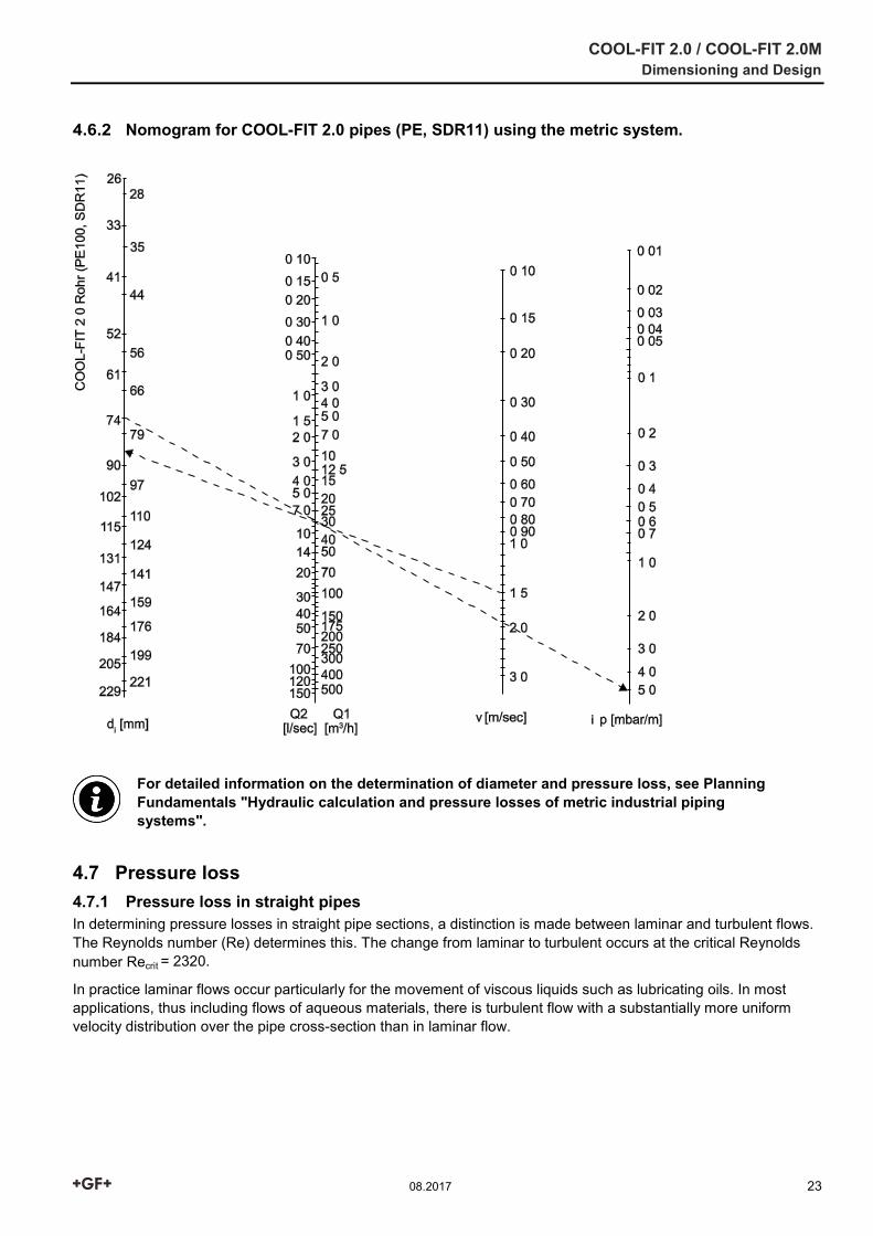
4.6 Nomogram for easy calculation of diameter and pressure loss The nomogram below can be used to simplify the determination of the diameter required .The pressure loss in the pipes can be read off per meter of the pipe length.
The pressure loss calculated using the nomogram only applies to flows of substances with density 1000 kg/m³, i.e. water. Further pressure losses from fittings, valves, etc. also need to be considered using the instructions that follow.
4.6.1 Using the nomogram Based on a flow velocity of 1.5 m/s, a line is drawn through the desired flow rate (i.e. 30 m³/h) to the axis which shows an internal diameter di (≈ 84 mm). Here, a closely matching diameter (74 mm for SDR11) and a second line is drawn back through the desired flow rate to the pressure drop axis Δp (5 mbar per meter of pipe).
COOL-FIT 2.0 / COOL-FIT 2.0M Dimensioning and Design
08.2017 23
4.6.2 Nomogram for COOL-FIT 2.0 pipes (PE, SDR11) using the metric system.
For detailed information on the determination of diameter and pressure loss, see Planning Fundamentals "Hydraulic calculation and pressure losses of metric industrial piping systems".
4.7 Pressure loss 4.7.1 Pressure loss in straight pipes In determining pressure losses in straight pipe sections, a distinction is made between laminar and turbulent flows. The Reynolds number (Re) determines this. The change from laminar to turbulent occurs at the critical Reynolds number Recrit = 2320.
In practice laminar flows occur particularly for the movement of viscous liquids such as lubricating oils. In most applications, thus including flows of aqueous materials, there is turbulent flow with a substantially more uniform velocity distribution over the pipe cross-section than in laminar flow.
COOL-FIT 2.0 / COOL-FIT 2.0M Dimensioning and Design
24 08.2017
The pressure loss in a straight pipe section is inversely proportional to the pipe diameter and is calculated as follows:
∆𝐩𝐑 = 𝛌 𝐋
𝐝𝐢
𝛒
𝟐 𝟏𝟎𝟐𝐯𝟐
ΔpR Pressure loss in the straight pipe run (bar) λ Pipe friction factor L Length of the straight pipe section (m) di Inner diameter of the pipe (mm) ρ Density of the flow material (kg/m³) (1 g/cm³ = 1000 kg/m³) v Flow velocity v (m/s)
In practice, when making a rough calculation (i.e. smooth plastic pipe and turbulent flow) it is enough to use the value = 0.02 to represent the hydraulic pressure loss.
4.7.2 Pressure losses in fittings Coefficient of resistance The pressure losses depend upon the type of fitting as well as on the flow in the fitting. The so-called coefficient of resistance (value) is used for calculations.
Fitting type Coefficient of resistance
radius of curvature R ζ value
90 ° bend 1.0 d 0.51
1.5 d 0.41
2.0 d 0.34
4.0 d 0.23
1.0 d 0.34
1.5 d 0.27
2.0 d 0.20
4.0 d 0.15
90 ° angle 1.2
45 ° angle 0.3
T-piece 1) 1.3
Reducer (contraction) 0.5
Reducer (enlargement) 1.0
Connections (flanges, fittings, welding between two pipes)
d >90 mm: 0.1 20 ≤ d ≤ 90 mm: 1.0 to 0.1:
d20: 1.0 d25: 0.9 d32: 0.8 d40: 0.7
d50: 0.6 d63: 0.4 d75: 0.3 d90: 0.1
1 For a more detailed view, differentiate between coalescence and separation. Values for z up to a maximum of 1.3 can be found in the respective literature. Usually the part of a tee in the overall pressure loss is very small, therefore in most cases = 1.3 can be used.
COOL-FIT 2.0 / COOL-FIT 2.0M Dimensioning and Design
08.2017 25
Calculation of the pressure loss To calculate the total pressure loss in all fittings in a pipeline, take the sum of the individual losses, i. e. the sum of all the ζ-values. The pressure loss can then be calculated according to the following formula:
∆𝐩𝐅𝐢 = ∑𝛇 𝐯𝟐
𝟐 𝟏𝟎𝟓 𝛒
ΔpFi Pressure loss of all fittings (bar) Σζ Sum of all individual losses v Flow velocity v (m/s) ρ Density of the medium in kg/m³ (1 g/cm³ = 1000 kg/m³)
4.7.3 Pressure losses in valves The kv factor is a convenient means of calculating the hydraulic flow rates for valves. It allows for all internal resistances and for practical purposes is regarded as reliable. It is defined as the flow rate of water in liters per minute with a pressure drop of 1 bar across the valve. The technical data of the GF Piping Systems valves contains the kv values as well as pressure loss charts. The latter make it possible to read off the pressure loss directly. But the pressure loss can also be calculated from the kv value according to the following formula:
∆𝐩𝐀𝐫 = (𝐐
𝐤𝐯)
𝟐
𝛒
𝟏𝟎𝟎𝟎
ΔpAr Pressure loss for the valve (bar) Q Flow rate (m³/h) ρ Density of the conveyed medium (kg/m³) (1 g/cc = 1000 kg/m³) kv Valve characteristic value (m³/h)
4.7.4 Pressure difference between the static pressure If the pipeline is installed vertically, then a geodetic pressure difference must be calculated for it. This pressure difference is calculated as follows:
∆𝐩𝐠𝐞𝐨𝐝 = ∆𝐇𝐠𝐞𝐨𝐝𝐩 𝟏𝟎−𝟒
Δpgeod Geodetic pressure difference (bar) ΔHgeod Difference in elevation of the pipeline (m) ρ Density of the medium (kg/m³) (1 g/cm³ = 1000 kg/m³)
COOL-FIT 2.0 / COOL-FIT 2.0M Dimensioning and Design
26 08.2017
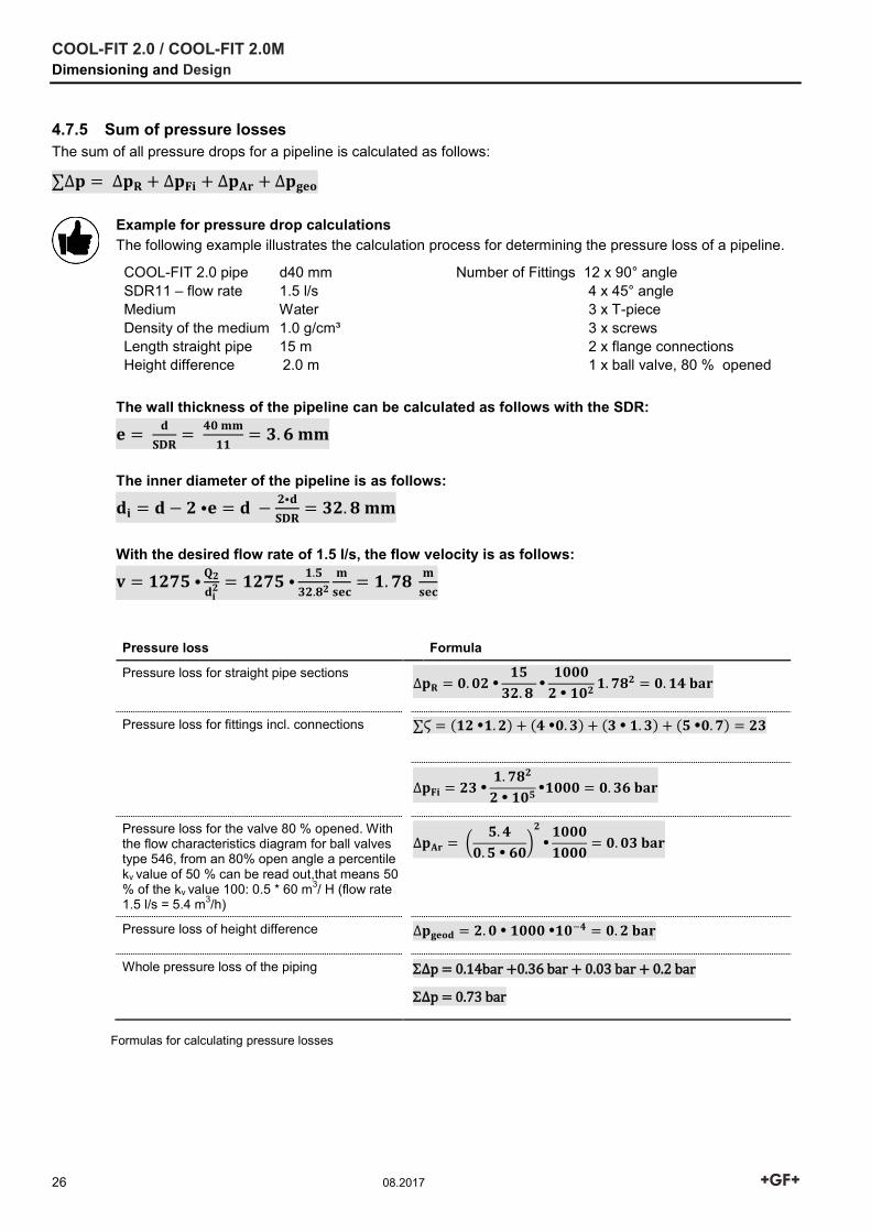
4.7.5 Sum of pressure losses The sum of all pressure drops for a pipeline is calculated as follows:
∑∆𝐩 = ∆𝐩𝐑 + ∆𝐩𝐅𝐢 + ∆𝐩𝐀𝐫 + ∆𝐩𝐠𝐞𝐨
Example for pressure drop calculations The following example illustrates the calculation process for determining the pressure loss of a pipeline.
COOL-FIT 2.0 pipe d40 mm SDR11 – flow rate 1.5 l/s Medium Water Density of the medium 1.0 g/cm³ Length straight pipe 15 m Height difference 2.0 m
Number of Fittings 12 x 90° angle 4 x 45° angle 3 x T-piece 3 x screws 2 x flange connections 1 x ball valve, 80 % opened
The wall thickness of the pipeline can be calculated as follows with the SDR:
𝐞 = 𝐝
𝐒𝐃𝐑=
𝟒𝟎 𝐦𝐦
𝟏𝟏= 𝟑. 𝟔 𝐦𝐦
The inner diameter of the pipeline is as follows:
𝐝𝐢 = 𝐝 − 𝟐 𝐞 = 𝐝 −𝟐𝐝
𝐒𝐃𝐑= 𝟑𝟐. 𝟖 𝐦𝐦
With the desired flow rate of 1.5 l/s, the flow velocity is as follows:
𝐯 = 𝟏𝟐𝟕𝟓 𝐐𝟐
𝐝𝐢𝟐 = 𝟏𝟐𝟕𝟓
𝟏.𝟓
𝟑𝟐.𝟖𝟐
𝐦
𝐬𝐞𝐜= 𝟏. 𝟕𝟖
𝐦
𝐬𝐞𝐜
Pressure loss Formula
Pressure loss for straight pipe sections ∆𝐩𝐑 = 𝟎. 𝟎𝟐
𝟏𝟓
𝟑𝟐. 𝟖
𝟏𝟎𝟎𝟎
𝟐 𝟏𝟎𝟐𝟏. 𝟕𝟖𝟐 = 𝟎. 𝟏𝟒 𝐛𝐚𝐫
Pressure loss for fittings incl. connections ∑Ϛ = (𝟏𝟐 𝟏. 𝟐) + (𝟒 𝟎. 𝟑) + (𝟑 𝟏. 𝟑) + (𝟓 𝟎. 𝟕) = 𝟐𝟑
∆𝐩𝐅𝐢 = 𝟐𝟑 𝟏. 𝟕𝟖𝟐
𝟐 𝟏𝟎𝟓𝟏𝟎𝟎𝟎 = 𝟎. 𝟑𝟔 𝐛𝐚𝐫
Pressure loss for the valve 80 % opened. With the flow characteristics diagram for ball valves type 546, from an 80% open angle a percentile kv value of 50 % can be read out,that means 50 % of the kv value 100: 0.5 * 60 m3/ H (flow rate 1.5 l/s = 5.4 m3/h)
∆𝐩𝐀𝐫 = (𝟓. 𝟒
𝟎. 𝟓 𝟔𝟎)
𝟐
𝟏𝟎𝟎𝟎
𝟏𝟎𝟎𝟎= 𝟎. 𝟎𝟑 𝐛𝐚𝐫
Pressure loss of height difference ∆𝐩𝐠𝐞𝐨𝐝 = 𝟐. 𝟎 𝟏𝟎𝟎𝟎 𝟏𝟎−𝟒 = 𝟎. 𝟐 𝐛𝐚𝐫
Whole pressure loss of the piping
Δp = 0.14bar +0.36 bar + 0.03 bar + 0.2 bar
Δp = 0.73 bar
Formulas for calculating pressure losses
COOL-FIT 2.0 / COOL-FIT 2.0M Dimensioning and Design
08.2017 27
4.8 Dimension comparison COOL-FIT 2.0 / 2.0M metal COOL-FIT 2.0 / 2.0M Stainless
steel Copper pipes
d (mm)
di (mm)
DN inches da (mm)
da (mm)
32 26.3 25 1 33.7 28
40 32.6 32 1¼ 42.4 35
50 4.8 40 1½ 48.3 42
63 51.4 50 2 60.3 54
75 61.4 65 2½ 75.3 76.1
90 73.6 80 3 88.9 88.9
110 90.0 100 4 114.3 108
140 114.6 125 5 140.3 -
d Nominal external diameter of PE pipe di Nominal internal diameter of pipe
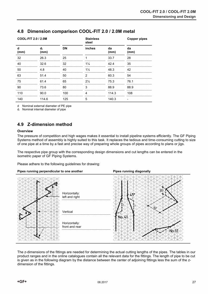
4.9 Z-dimension method Overview The pressure of competition and high wages makes it essential to install pipeline systems efficiently. The GF Piping Systems method of assembly is highly suited to this task. It replaces the tedious and time-consuming cutting to size of one pipe at a time by a fast and precise way of preparing whole groups of pipes according to plans or jigs. The respective pipe group with the corresponding design dimensions and cut lengths can be entered in the isometric paper of GF Piping Systems. Please adhere to the following guidelines for drawing:
Pipes running perpendicular to one another Pipes running diagonally
Horizontally: left and right
Vertical
Horizontally: front and rear
The z-dimensions of the fittings are needed for determining the actual cutting lengths of the pipes. The tables in our product ranges and in the online catalogues contain all the relevant data for the fittings. The length of pipe to be cut is given as in the following diagram by the distance between the center of adjoining fittings less the sum of the z-dimension of the fittings.
COOL-FIT 2.0 / COOL-FIT 2.0M Dimensioning and Design
28 08.2017
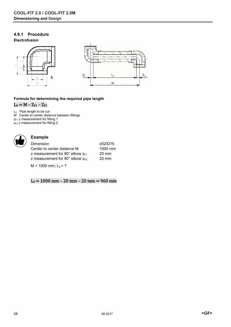
4.9.1 Procedure Electrofusion
Formula for determining the required pipe length L0 = M – ZF1 – ZF2
L0 Pipe length to be cut M Center to center distance between fittings zF1 z measurement for fitting 1 zF2 z measurement for fitting 2
Example Dimension d32/D75 Center to center distance M 1000 mm z measurement for 90° elbow zF1 20 mm z measurement for 90° elbow zF2 20 mm
M = 1000 mm; L0 = ?
L0 = 1000 mm – 20 mm – 20 mm = 960 mm
COOL-FIT 2.0 / COOL-FIT 2.0M Dimensioning and Design
08.2017 29
4.9.2 Measuring Sheet
COOL-FIT 2.0 / COOL-FIT 2.0M Dimensioning and Design
30 08.2017
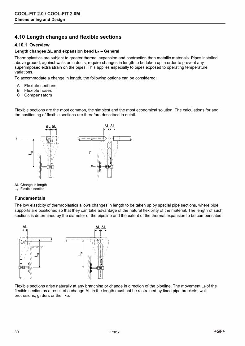
4.10 Length changes and flexible sections 4.10.1 Overview Length changes ΔL and expansion bend LB – General Thermoplastics are subject to greater thermal expansion and contraction than metallic materials. Pipes installed above ground, against walls or in ducts, require changes in length to be taken up in order to prevent any superimposed extra strain on the pipes. This applies especially to pipes exposed to operating temperature variations. To accommodate a change in length, the following options can be considered:
A Flexible sections B Flexible hoses C Compensators
Flexible sections are the most common, the simplest and the most economical solution. The calculations for and the positioning of flexible sections are therefore described in detail.
ΔL Change in length LB Flexible section Fundamentals The low elasticity of thermoplastics allows changes in length to be taken up by special pipe sections, where pipe supports are positioned so that they can take advantage of the natural flexibility of the material. The length of such sections is determined by the diameter of the pipeline and the extent of the thermal expansion to be compensated.
Flexible sections arise naturally at any branching or change in direction of the pipeline. The movement LB of the flexible section as a result of a change ΔL in the length must not be restrained by fixed pipe brackets, wall protrusions, girders or the like.
COOL-FIT 2.0 / COOL-FIT 2.0M Dimensioning and Design
08.2017 31
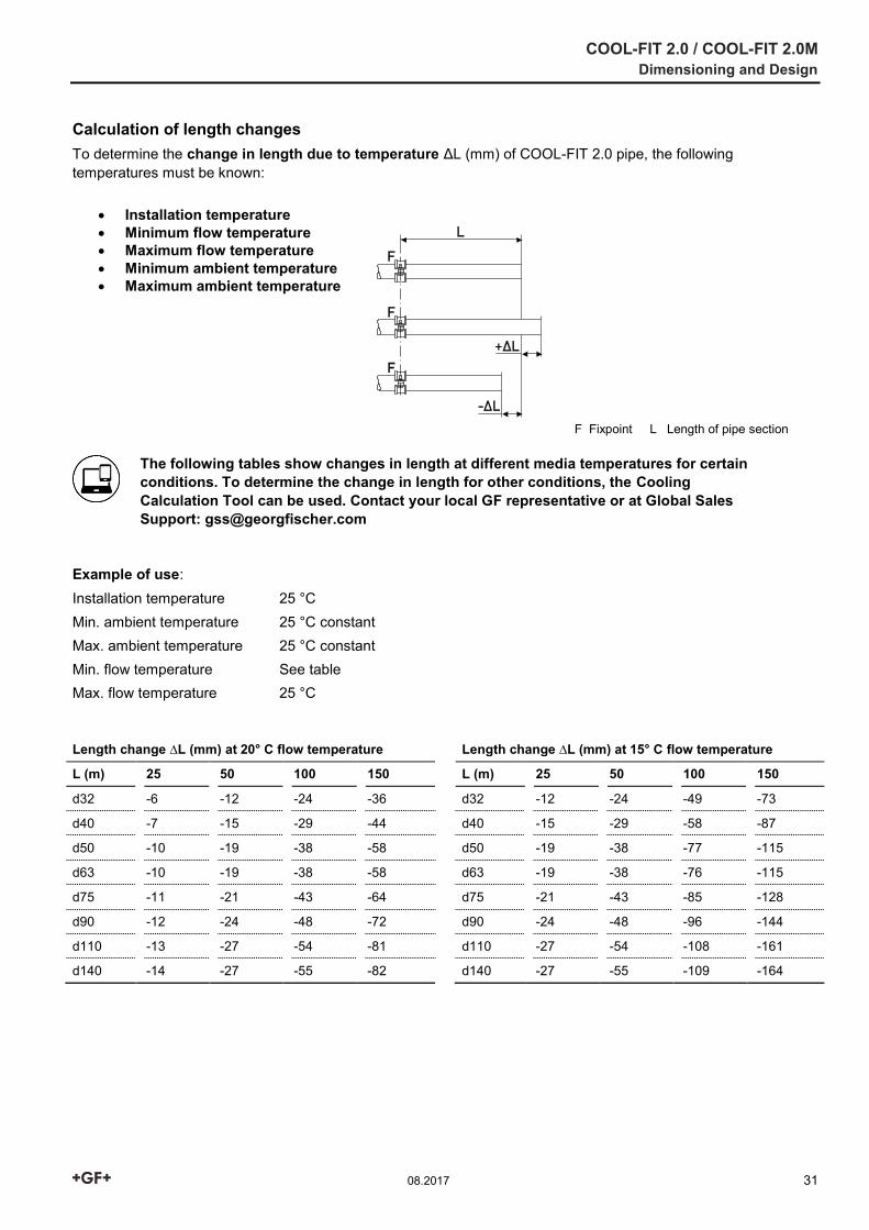
Calculation of length changes To determine the change in length due to temperature ΔL (mm) of COOL-FIT 2.0 pipe, the following temperatures must be known:
Installation temperature Minimum flow temperature Maximum flow temperature Minimum ambient temperature Maximum ambient temperature
F Fixpoint L Length of pipe section
The following tables show changes in length at different media temperatures for certain conditions. To determine the change in length for other conditions, the Cooling Calculation Tool can be used. Contact your local GF representative or at Global Sales Support: [email protected]
Example of use: Installation temperature 25 °C Min. ambient temperature 25 °C constant Max. ambient temperature 25 °C constant Min. flow temperature See table Max. flow temperature 25 °C
Length change ∆L (mm) at 20° C flow temperature Length change ∆L (mm) at 15° C flow temperature
L (m) 25 50 100 150 L (m) 25 50 100 150
d32 -6 -12 -24 -36 d32 -12 -24 -49 -73
d40 -7 -15 -29 -44 d40 -15 -29 -58 -87
d50 -10 -19 -38 -58 d50 -19 -38 -77 -115
d63 -10 -19 -38 -58 d63 -19 -38 -76 -115
d75 -11 -21 -43 -64 d75 -21 -43 -85 -128
d90 -12 -24 -48 -72 d90 -24 -48 -96 -144
d110 -13 -27 -54 -81 d110 -27 -54 -108 -161
d140 -14 -27 -55 -82 d140 -27 -55 -109 -164
COOL-FIT 2.0 / COOL-FIT 2.0M Dimensioning and Design
32 08.2017
Length change ∆L (mm) at 10° C flow temperature Length change ∆L (mm) at 5° C flow temperature
L (m) 25 50 100 150 L (m) 25 50 100 150
d32 -18 -36 -73 -109 d32 -24 -49 -97 -146
d40 -22 -44 -87 -131 d40 -29 -58 -116 -175
d50 -29 -58 -115 -173 d50 -39 -77 -154 -213
d63 -29 -57 -115 -172 d63 -38 -76 -153 -229
d75 -32 -64 -128 -191 d75 -43 -85 -170 -255
d90 -36 -72 -144 -216 d90 -48 -96 -192 -288
d110 -40 -81 -161 -242 d110 -54 -108 -215 -323
d140 -41 -82 -164 -246 d140 -55 -109 -218 -327
L laid pipe length
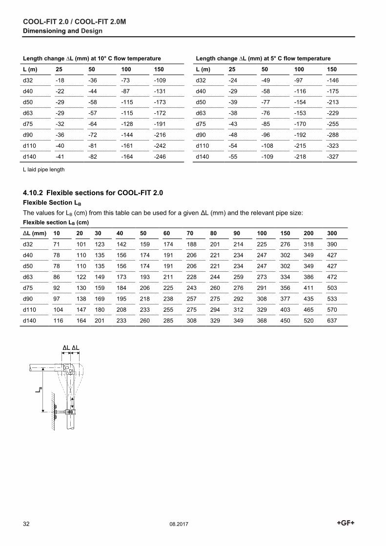
4.10.2 Flexible sections for COOL-FIT 2.0 Flexible Section LB The values for LB (cm) from this table can be used for a given ΔL (mm) and the relevant pipe size:
Flexible section LB (cm)
ΔL (mm) 10 20 30 40 50 60 70 80 90 100 150 200 300
d32 71 101 123 142 159 174 188 201 214 225 276 318 390
d40 78 110 135 156 174 191 206 221 234 247 302 349 427
d50 78 110 135 156 174 191 206 221 234 247 302 349 427
d63 86 122 149 173 193 211 228 244 259 273 334 386 472
d75 92 130 159 184 206 225 243 260 276 291 356 411 503
d90 97 138 169 195 218 238 257 275 292 308 377 435 533
d110 104 147 180 208 233 255 275 294 312 329 403 465 570
d140 116 164 201 233 260 285 308 329 349 368 450 520 637
COOL-FIT 2.0 / COOL-FIT 2.0M Dimensioning and Design
08.2017 33
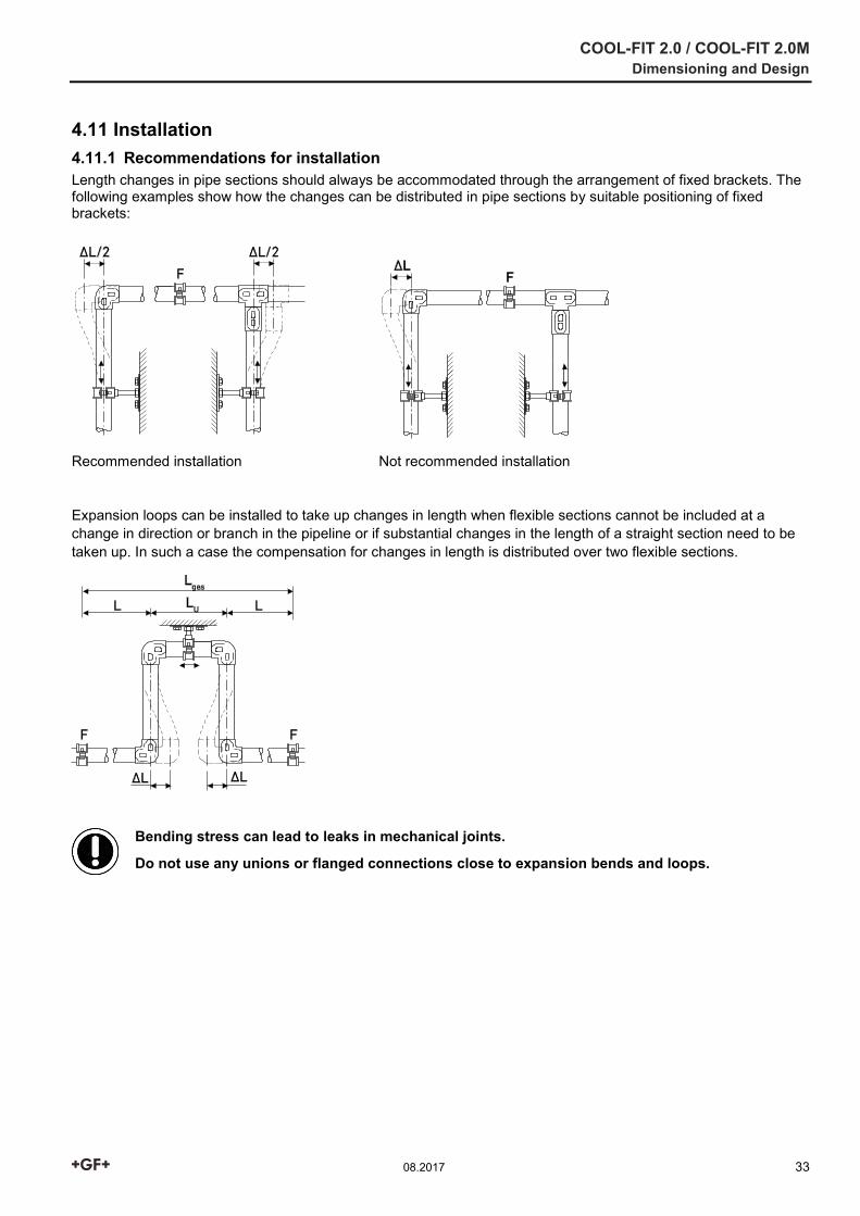
4.11 Installation 4.11.1 Recommendations for installation Length changes in pipe sections should always be accommodated through the arrangement of fixed brackets. The following examples show how the changes can be distributed in pipe sections by suitable positioning of fixed brackets:
Recommended installation Not recommended installation
Expansion loops can be installed to take up changes in length when flexible sections cannot be included at a change in direction or branch in the pipeline or if substantial changes in the length of a straight section need to be taken up. In such a case the compensation for changes in length is distributed over two flexible sections.
Bending stress can lead to leaks in mechanical joints.
Do not use any unions or flanged connections close to expansion bends and loops.
COOL-FIT 2.0 / COOL-FIT 2.0M Dimensioning and Design
34 08.2017
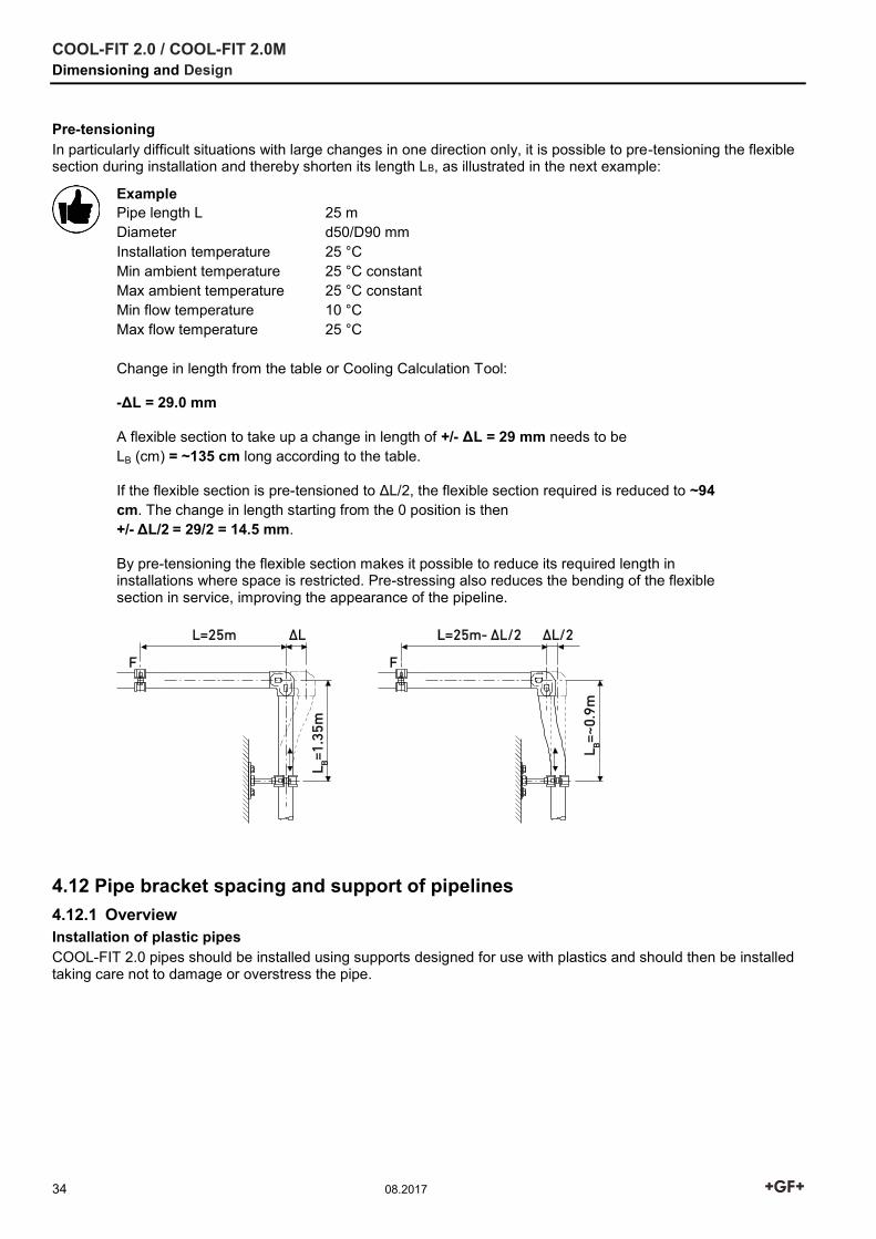
Pre-tensioning In particularly difficult situations with large changes in one direction only, it is possible to pre-tensioning the flexible section during installation and thereby shorten its length LB, as illustrated in the next example:
Example Pipe length L 25 m Diameter d50/D90 mm Installation temperature 25 °C Min ambient temperature 25 °C constant Max ambient temperature 25 °C constant Min flow temperature 10 °C Max flow temperature 25 °C Change in length from the table or Cooling Calculation Tool:
-ΔL = 29.0 mm
A flexible section to take up a change in length of +/- ΔL = 29 mm needs to be LB (cm) = ~135 cm long according to the table.
If the flexible section is pre-tensioned to ΔL/2, the flexible section required is reduced to ~94 cm. The change in length starting from the 0 position is then +/- ΔL/2 = 29/2 = 14.5 mm.
By pre-tensioning the flexible section makes it possible to reduce its required length in installations where space is restricted. Pre-stressing also reduces the bending of the flexible section in service, improving the appearance of the pipeline.
4.12 Pipe bracket spacing and support of pipelines 4.12.1 Overview Installation of plastic pipes COOL-FIT 2.0 pipes should be installed using supports designed for use with plastics and should then be installed taking care not to damage or overstress the pipe.
COOL-FIT 2.0 / COOL-FIT 2.0M Dimensioning and Design
08.2017 35
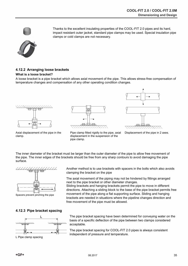
Thanks to the excellent insulating properties of the COOL-FIT 2.0 pipes and its hard, impact resistant outer jacket, standard pipe clamps may be used. Special insulation pipe clamps or cold clamps are not necessary.
4.12.2 Arranging loose brackets What is a loose bracket? A loose bracket is a pipe bracket which allows axial movement of the pipe. This allows stress-free compensation of temperature changes and compensation of any other operating condition changes.
Axial displacement of the pipe in the clamp.
Pipe clamp fitted rigidly to the pipe, axial displacement in the suspension of the pipe clamp.
Displacement of the pipe in 2 axes.
The inner diameter of the bracket must be larger than the outer diameter of the pipe to allow free movement of the pipe. The inner edges of the brackets should be free from any sharp contours to avoid damaging the pipe surface.
Spacers prevent pinching the pipe
Another method is to use brackets with spacers in the bolts which also avoids clamping the bracket on the pipe
The axial movement of the piping may not be hindered by fittings arranged next to the pipe bracket or other diameter changes. Sliding brackets and hanging brackets permit the pipe to move in different directions. Attaching a sliding block to the base of the pipe bracket permits free movement of the pipe along a flat supporting surface. Sliding and hanging brackets are needed in situations where the pipeline changes direction and free movement of the pipe must be allowed.
4.12.3 Pipe bracket spacing
L Pipe clamp spacing
The pipe bracket spacing have been determined for conveying water on the basis of a specific deflection of the pipe between two clamps considered acceptable.
The pipe bracket spacing for COOL-FIT 2.0 pipes is always consistent independent of pressure and temperature.
COOL-FIT 2.0 / COOL-FIT 2.0M Dimensioning and Design
36 08.2017
Pipe clamp intervals L for COOL-FIT 2.0 d/D (mm)
32/75 40/90 50/90 63/110 75/125 90/140 110/160 140/200
L (mm) 1600 1700 1700 1850 1950 2000 2100 2350
Pipe clamp intervals L for COOL-FIT 2.0M d/D (mm)
32/75 40/90 50/90 63/110 75/125 90/140 110/160
L (mm) 2400 2600 2500 2700 2900 3000 3200
The pipe clamp intervals from the table can be increased by 30% for vertical pipes. Multiply the values given by 1.3 in this case.
Pipes which are axially clamped and rigidly fixed must be tested for their resistance to kinking. In most cases, this test results in a reduction of the maximum internal pressure and more tightly spaced supports. The forces acting on the fixed points should be considered.
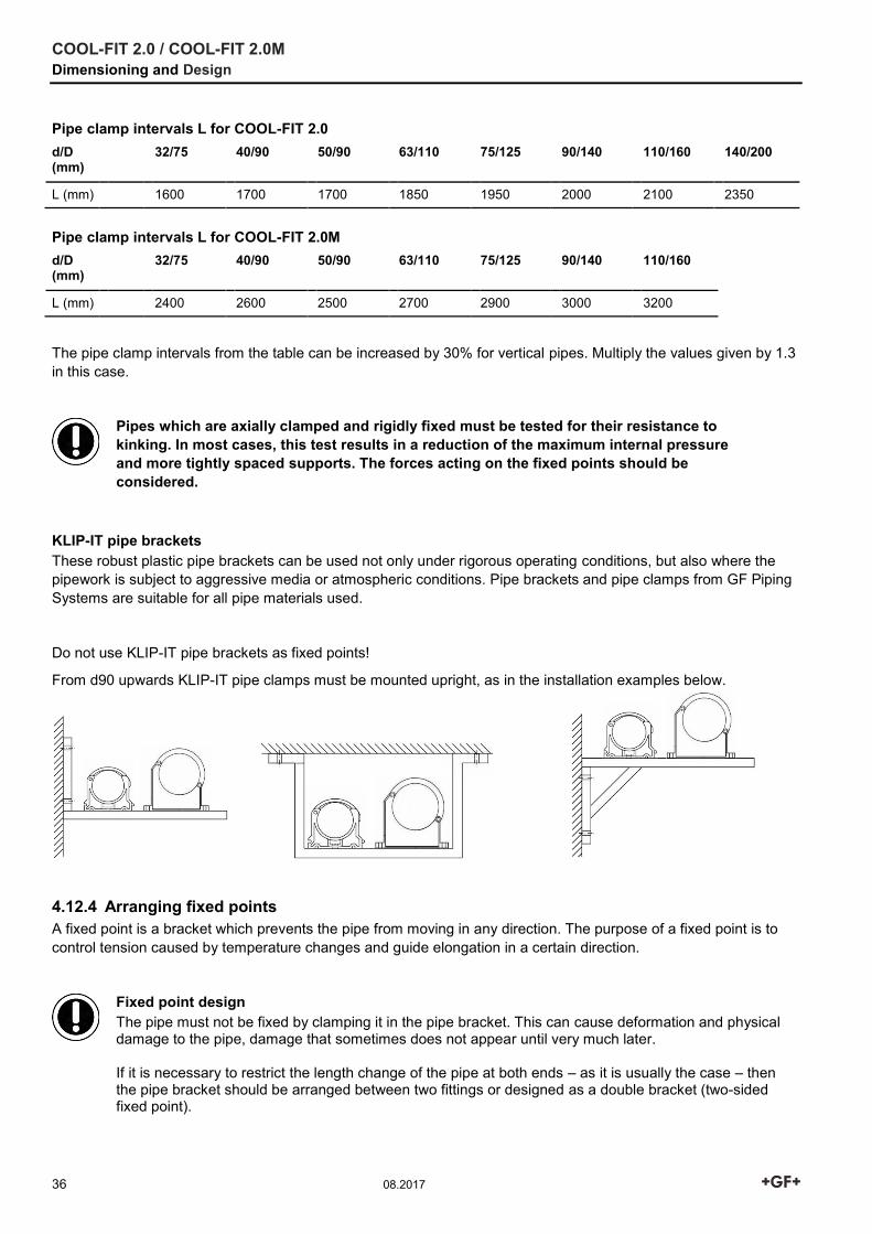
KLIP-IT pipe brackets These robust plastic pipe brackets can be used not only under rigorous operating conditions, but also where the pipework is subject to aggressive media or atmospheric conditions. Pipe brackets and pipe clamps from GF Piping Systems are suitable for all pipe materials used.
Do not use KLIP-IT pipe brackets as fixed points!
From d90 upwards KLIP-IT pipe clamps must be mounted upright, as in the installation examples below.
4.12.4 Arranging fixed points A fixed point is a bracket which prevents the pipe from moving in any direction. The purpose of a fixed point is to control tension caused by temperature changes and guide elongation in a certain direction.
Fixed point design The pipe must not be fixed by clamping it in the pipe bracket. This can cause deformation and physical damage to the pipe, damage that sometimes does not appear until very much later. If it is necessary to restrict the length change of the pipe at both ends – as it is usually the case – then the pipe bracket should be arranged between two fittings or designed as a double bracket (two-sided fixed point).
COOL-FIT 2.0 / COOL-FIT 2.0M Dimensioning and Design
08.2017 37
Placing a pipe bracket immediately adjacent to a fitting restricts movement due to changes in length to one direction (one-sided fixed point).
One-sided fixed point
Two-sided fixed point
Pipe brackets must be robust and mounted firmly to be able to take up the forces arising from changes in length in the pipeline. Hanging brackets or KLIP-IT pipe brackets are unsuitable for use as fixed points.
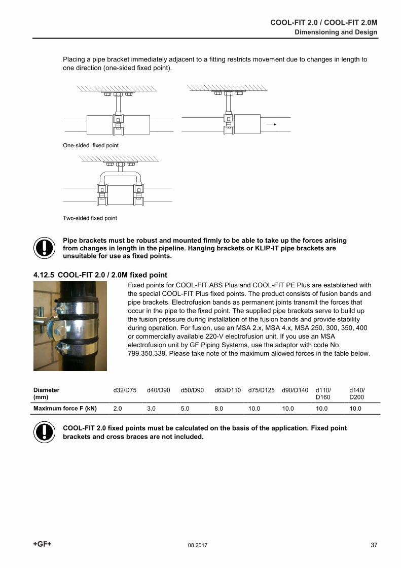
4.12.5 COOL-FIT 2.0 / 2.0M fixed point
Fixed points for COOL-FIT ABS Plus and COOL-FIT PE Plus are established with the special COOL-FIT Plus fixed points. The product consists of fusion bands and pipe brackets. Electrofusion bands as permanent joints transmit the forces that occur in the pipe to the fixed point. The supplied pipe brackets serve to build up the fusion pressure during installation of the fusion bands and provide stability during operation. For fusion, use an MSA 2.x, MSA 4.x, MSA 250, 300, 350, 400 or commercially available 220-V electrofusion unit. If you use an MSA electrofusion unit by GF Piping Systems, use the adaptor with code No. 799.350.339. Please take note of the maximum allowed forces in the table below.
Diameter (mm)
d32/D75 d40/D90 d50/D90 d63/D110 d75/D125 d90/D140 d110/ D160
d140/ D200
Maximum force F (kN) 2.0 3.0 5.0 8.0 10.0 10.0 10.0 10.0
COOL-FIT 2.0 fixed points must be calculated on the basis of the application. Fixed point brackets and cross braces are not included.
COOL-FIT 2.0 / COOL-FIT 2.0M Dimensioning and Design
38 08.2017
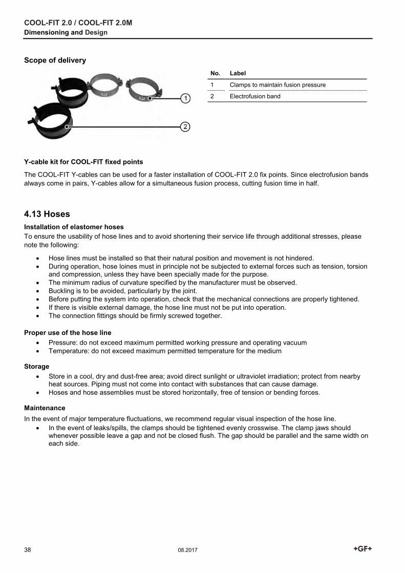
Scope of delivery
No. Label
1 Clamps to maintain fusion pressure
2 Electrofusion band
Y-cable kit for COOL-FIT fixed points
The COOL-FIT Y-cables can be used for a faster installation of COOL-FIT 2.0 fix points. Since electrofusion bands always come in pairs, Y-cables allow for a simultaneous fusion process, cutting fusion time in half.
4.13 Hoses Installation of elastomer hoses To ensure the usability of hose lines and to avoid shortening their service life through additional stresses, please note the following:
Hose lines must be installed so that their natural position and movement is not hindered. During operation, hose loines must in principle not be subjected to external forces such as tension, torsion
and compression, unless they have been specially made for the purpose. The minimum radius of curvature specified by the manufacturer must be observed. Buckling is to be avoided, particularly by the joint. Before putting the system into operation, check that the mechanical connections are properly tightened. If there is visible external damage, the hose line must not be put into operation. The connection fittings should be firmly screwed together.
Proper use of the hose line
Pressure: do not exceed maximum permitted working pressure and operating vacuum Temperature: do not exceed maximum permitted temperature for the medium
Storage
Store in a cool, dry and dust-free area; avoid direct sunlight or ultraviolet irradiation; protect from nearby heat sources. Piping must not come into contact with substances that can cause damage.
Hoses and hose assemblies must be stored horizontally, free of tension or bending forces.
Maintenance In the event of major temperature fluctuations, we recommend regular visual inspection of the hose line.
In the event of leaks/spills, the clamps should be tightened evenly crosswise. The clamp jaws should whenever possible leave a gap and not be closed flush. The gap should be parallel and the same width on each side.
COOL-FIT 2.0 / COOL-FIT 2.0M Dimensioning and Design
08.2017 39
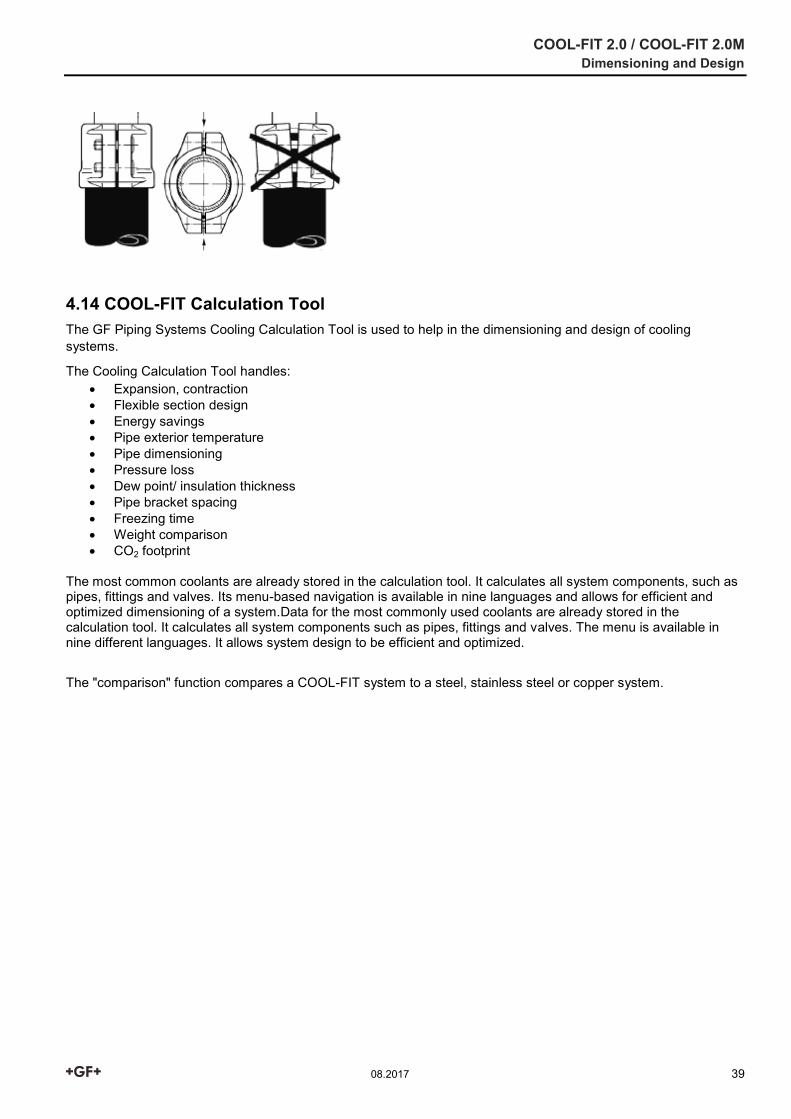
4.14 COOL-FIT Calculation Tool The GF Piping Systems Cooling Calculation Tool is used to help in the dimensioning and design of cooling systems.
The Cooling Calculation Tool handles: Expansion, contraction Flexible section design Energy savings Pipe exterior temperature Pipe dimensioning Pressure loss Dew point/ insulation thickness Pipe bracket spacing Freezing time Weight comparison CO2 footprint
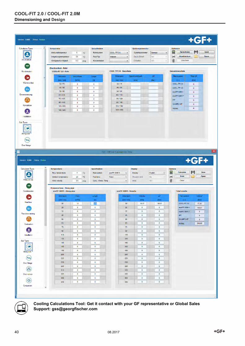
The most common coolants are already stored in the calculation tool. It calculates all system components, such as pipes, fittings and valves. Its menu-based navigation is available in nine languages and allows for efficient and optimized dimensioning of a system.Data for the most commonly used coolants are already stored in the calculation tool. It calculates all system components such as pipes, fittings and valves. The menu is available in nine different languages. It allows system design to be efficient and optimized.
The "comparison" function compares a COOL-FIT system to a steel, stainless steel or copper system.
COOL-FIT 2.0 / COOL-FIT 2.0M Dimensioning and Design
40 08.2017
Cooling Calculations Tool: Get it contact with your GF representative or Global Sales Support: [email protected]
COOL-FIT 2.0 / COOL-FIT 2.0M Jointing and Installation
08.2017 41
5 Jointing and Installation
5.1 Jointing of COOL-FIT 2.0/2.0M
For general notes and information on electrofusion, see Planning Fundamentals Chapter 12 “Jointing technology", section 10 "Electrofusion joints".
5.1.1 General advice The quality of a weld is largely determined by careful preparation. The welding surface must be protected from adverse weather conditions such as rain, snow or wind. The permissible temperature range for fusion is -10 °C to 45 °C. National regulations must be observed. In direct sunlight, shielding of the welding area can help to create an even temperature profile around the whole circumference of the pipe. It is particularly important to ensure that the climate conditions are the same for both the electrofusion machine and the welding area.
5.1.2 Executing electrofusion Protect the welding area The surfaces to be welded on the pipe and the fitting must be carefully protected from dirt, grease, oils and lubricants. Only cleaning agents suitable for PE must be used.
No fats (i.e. hand cream, oily rags, silicone, etc.) must be introduced into the fusion zone!
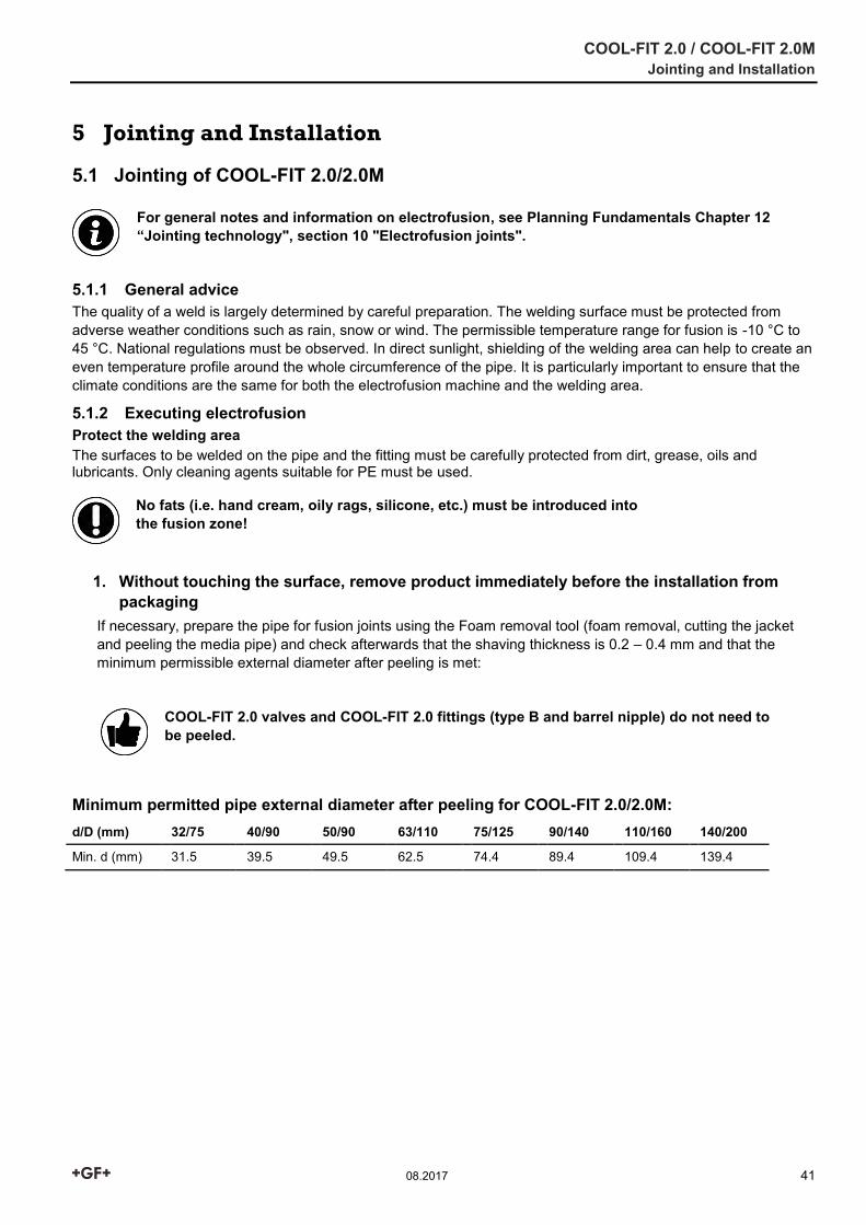
1. Without touching the surface, remove product immediately before the installation from packaging
If necessary, prepare the pipe for fusion joints using the Foam removal tool (foam removal, cutting the jacket and peeling the media pipe) and check afterwards that the shaving thickness is 0.2 – 0.4 mm and that the minimum permissible external diameter after peeling is met:
COOL-FIT 2.0 valves and COOL-FIT 2.0 fittings (type B and barrel nipple) do not need to be peeled.
Minimum permitted pipe external diameter after peeling for COOL-FIT 2.0/2.0M: d/D (mm) 32/75 40/90 50/90 63/110 75/125 90/140 110/160 140/200
Min. d (mm) 31.5 39.5 49.5 62.5 74.4 89.4 109.4 139.4
COOL-FIT 2.0 / COOL-FIT 2.0M Jointing and Installation
42 08.2017
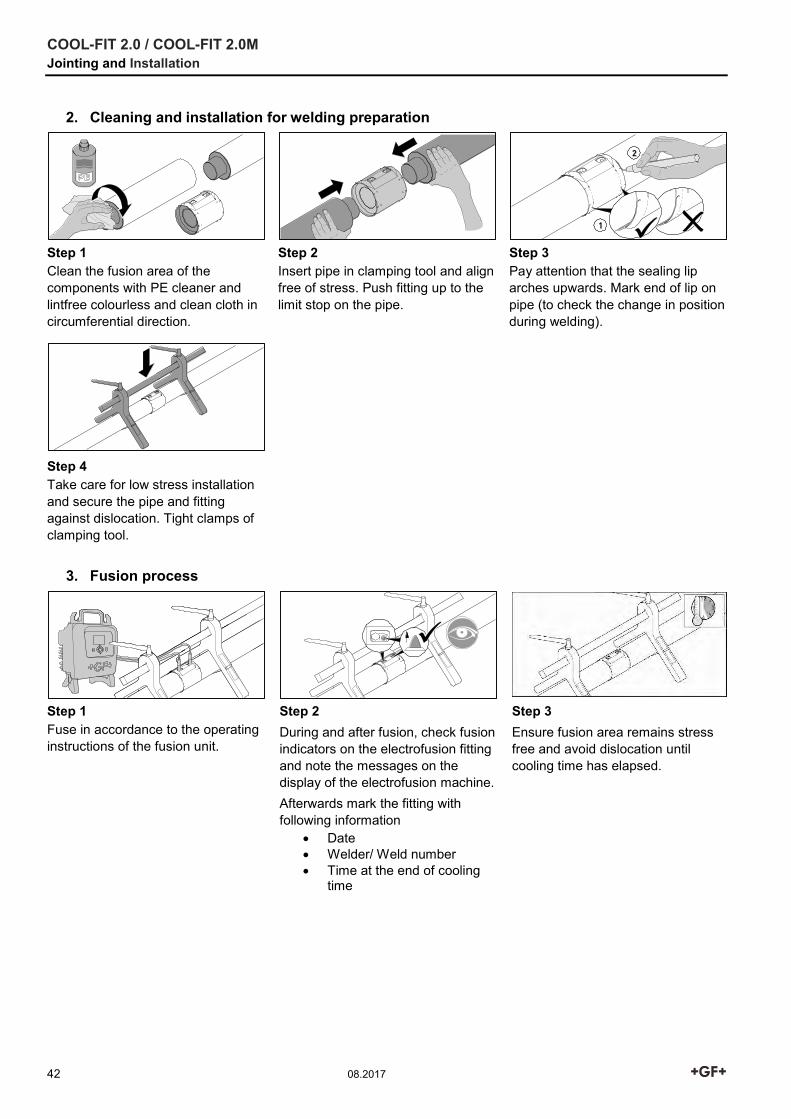
2. Cleaning and installation for welding preparation
Step 1 Clean the fusion area of the components with PE cleaner and lintfree colourless and clean cloth in circumferential direction.
Step 2 Insert pipe in clamping tool and align free of stress. Push fitting up to the limit stop on the pipe.
Step 3 Pay attention that the sealing lip arches upwards. Mark end of lip on pipe (to check the change in position during welding).
Step 4 Take care for low stress installation and secure the pipe and fitting against dislocation. Tight clamps of clamping tool.
3. Fusion process
Step 1 Fuse in accordance to the operating instructions of the fusion unit.
Step 2 During and after fusion, check fusion indicators on the electrofusion fitting and note the messages on the display of the electrofusion machine. Afterwards mark the fitting with following information
Date Welder/ Weld number Time at the end of cooling
time
Step 3 Ensure fusion area remains stress free and avoid dislocation until cooling time has elapsed.
COOL-FIT 2.0 / COOL-FIT 2.0M Jointing and Installation
08.2017 43
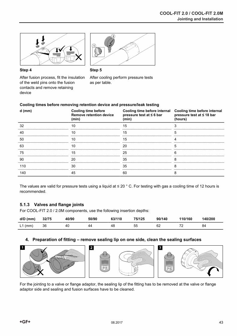
Step 4
After fusion process, fit the insulation of the weld pins onto the fusion contacts and remove retaining device
Step 5
After cooling perform pressure tests as per table.
Cooling times before removing retention device and pressure/leak testing d (mm) Cooling time before
Remove retention device (min)
Cooling time before internal pressure test at ≤ 6 bar (min)
Cooling time before internal pressure test at ≤ 18 bar (hours)
32 10 15 3
40 10 15 5
50 10 15 4
63 10 20 5
75 15 25 6
90 20 35 8
110 30 35 8
140 45 60 8
The values are valid for pressure tests using a liquid at ≤ 20 ° C. For testing with gas a cooling time of 12 hours is recommended.
5.1.3 Valves and flange joints For COOL-FIT 2.0 / 2.0M components, use the following insertion depths:
d/D (mm) 32/75 40/90 50/90 63/110 75/125 90/140 110/160 140/200
L1 (mm) 36 40 44 48 55 62 72 84
4. Preparation of fitting – remove sealing lip on one side, clean the sealing surfaces
For the jointing to a valve or flange adaptor, the sealing lip of the fitting has to be removed at the valve or flange adaptor side and sealing and fusion surfaces have to be cleaned.
1 2 3
COOL-FIT 2.0 / COOL-FIT 2.0M Jointing and Installation
44 08.2017
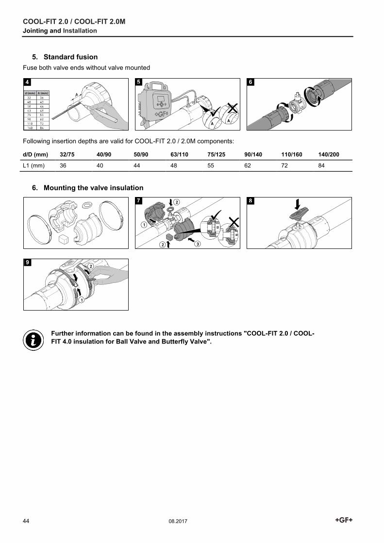
5. Standard fusion Fuse both valve ends without valve mounted
Following insertion depths are valid for COOL-FIT 2.0 / 2.0M components:
d/D (mm) 32/75 40/90 50/90 63/110 75/125 90/140 110/160 140/200
L1 (mm) 36 40 44 48 55 62 72 84
6. Mounting the valve insulation
Further information can be found in the assembly instructions "COOL-FIT 2.0 / COOL-FIT 4.0 insulation for Ball Valve and Butterfly Valve".
4 5 6
7 8
9
COOL-FIT 2.0 / COOL-FIT 2.0M Jointing and Installation
08.2017 45
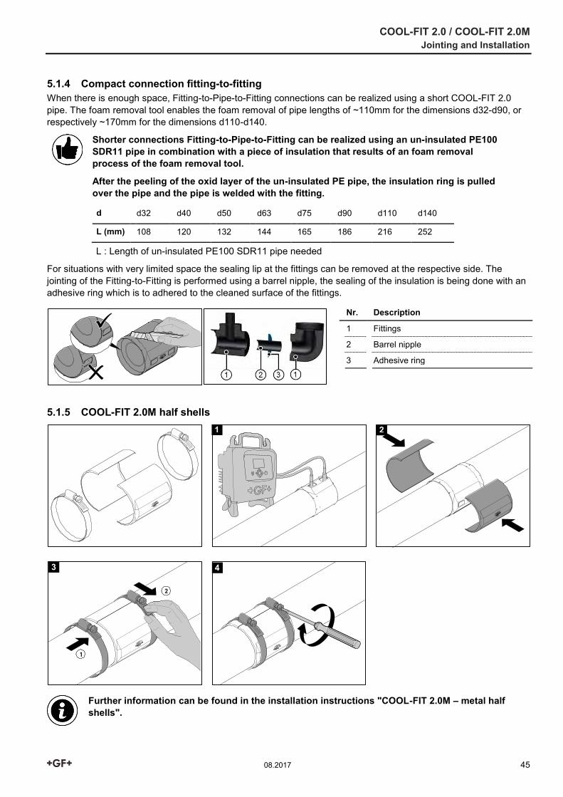
5.1.4 Compact connection fitting-to-fitting When there is enough space, Fitting-to-Pipe-to-Fitting connections can be realized using a short COOL-FIT 2.0 pipe. The foam removal tool enables the foam removal of pipe lengths of ~110mm for the dimensions d32-d90, or respectively ~170mm for the dimensions d110-d140.
Shorter connections Fitting-to-Pipe-to-Fitting can be realized using an un-insulated PE100 SDR11 pipe in combination with a piece of insulation that results of an foam removal process of the foam removal tool.
After the peeling of the oxid layer of the un-insulated PE pipe, the insulation ring is pulled over the pipe and the pipe is welded with the fitting.
d d32 d40 d50 d63 d75 d90 d110 d140
L (mm) 108 120 132 144 165 186 216 252
L : Length of un-insulated PE100 SDR11 pipe needed
For situations with very limited space the sealing lip at the fittings can be removed at the respective side. The jointing of the Fitting-to-Fitting is performed using a barrel nipple, the sealing of the insulation is being done with an adhesive ring which is to adhered to the cleaned surface of the fittings.
Nr. Description
1 Fittings
2 Barrel nipple
3 Adhesive ring
5.1.5 COOL-FIT 2.0M half shells
Further information can be found in the installation instructions "COOL-FIT 2.0M – metal half shells".
1 2
3 4
COOL-FIT 2.0 / COOL-FIT 2.0M Jointing and Installation
46 08.2017
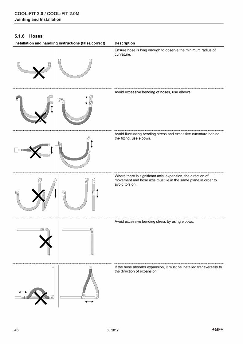
5.1.6 Hoses Installation and handling instructions (false/correct) Description
Ensure hose is long enough to observe the minimum radius of curvature.
Avoid excessive bending of hoses, use elbows.
Avoid fluctuating bending stress and excessive curvature behind the fitting, use elbows.
Where there is significant axial expansion, the direction of movement and hose axis must lie in the same plane in order to avoid torsion.
Avoid excessive bending stress by using elbows.
If the hose absorbs expansion, it must be installed transversally to the direction of expansion.
COOL-FIT 2.0 / COOL-FIT 2.0M Jointing and Installation
08.2017 47
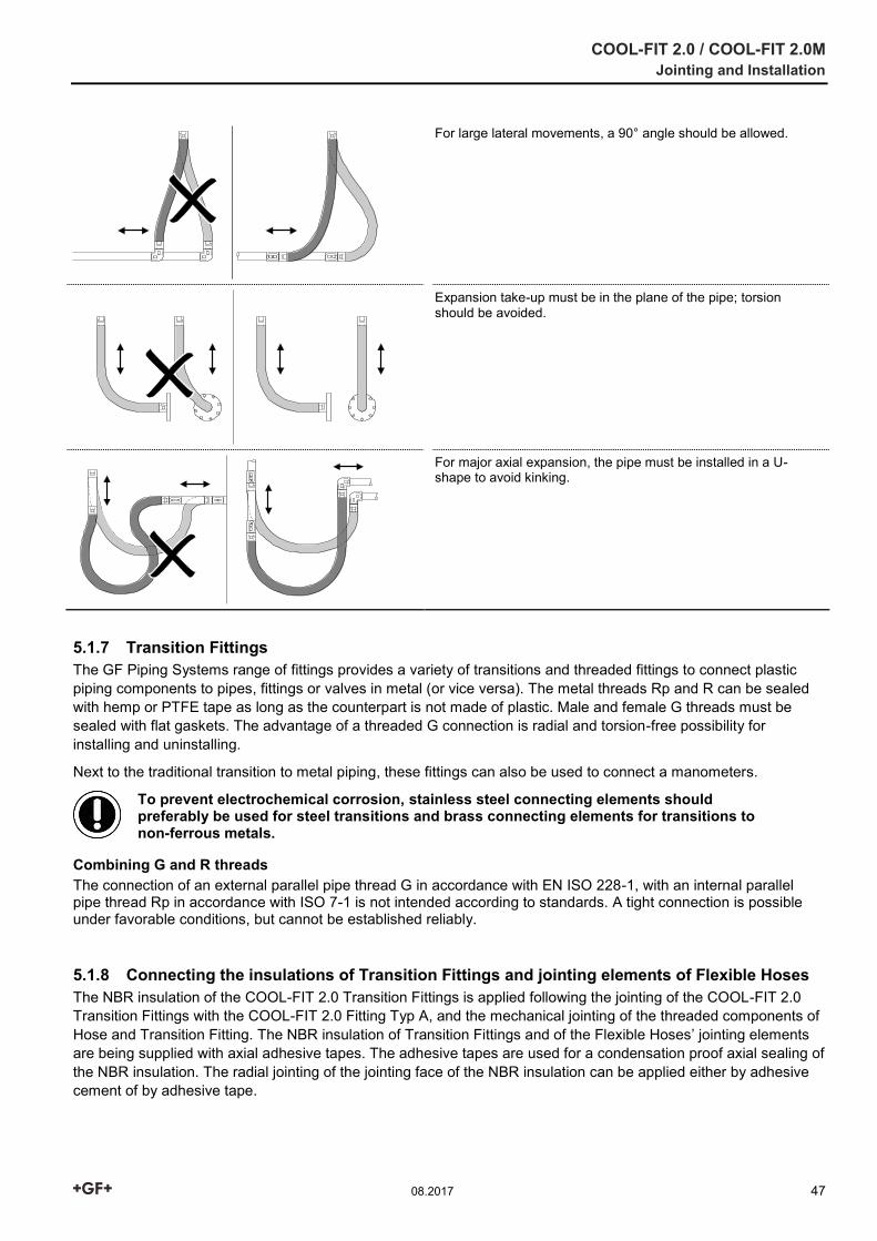
For large lateral movements, a 90° angle should be allowed.
Expansion take-up must be in the plane of the pipe; torsion should be avoided.
For major axial expansion, the pipe must be installed in a U-shape to avoid kinking.
5.1.7 Transition Fittings The GF Piping Systems range of fittings provides a variety of transitions and threaded fittings to connect plastic piping components to pipes, fittings or valves in metal (or vice versa). The metal threads Rp and R can be sealed with hemp or PTFE tape as long as the counterpart is not made of plastic. Male and female G threads must be sealed with flat gaskets. The advantage of a threaded G connection is radial and torsion-free possibility for installing and uninstalling.
Next to the traditional transition to metal piping, these fittings can also be used to connect a manometers.
To prevent electrochemical corrosion, stainless steel connecting elements should preferably be used for steel transitions and brass connecting elements for transitions to non-ferrous metals.
Combining G and R threads The connection of an external parallel pipe thread G in accordance with EN ISO 228-1, with an internal parallel pipe thread Rp in accordance with ISO 7-1 is not intended according to standards. A tight connection is possible under favorable conditions, but cannot be established reliably.
5.1.8 Connecting the insulations of Transition Fittings and jointing elements of Flexible Hoses The NBR insulation of the COOL-FIT 2.0 Transition Fittings is applied following the jointing of the COOL-FIT 2.0 Transition Fittings with the COOL-FIT 2.0 Fitting Typ A, and the mechanical jointing of the threaded components of Hose and Transition Fitting. The NBR insulation of Transition Fittings and of the Flexible Hoses’ jointing elements are being supplied with axial adhesive tapes. The adhesive tapes are used for a condensation proof axial sealing of the NBR insulation. The radial jointing of the jointing face of the NBR insulation can be applied either by adhesive cement of by adhesive tape.
COOL-FIT 2.0 / COOL-FIT 2.0M Jointing and Installation
48 08.2017
Jointing Instructions for the adhesive cement The adhesive should be thoroughly stirred before use. A thin film is applied by means of the brush to both surfaces to be bonded. Doing this, the consumption is ~0.2 – 0.25kg/m2.
The open joint time is about 3:15 minutes depending on temperature and humidity of air.
Before the coated surfaces are brought together the, the adhesive must still be tacky but should not transfer to the skin when finger-tested. The surfaces should be brought together quickly and firmly and should be held together for a few seconds.
The recommended temperature and for storage and processing is in the range between +15°C and 25°C.The adhesive should not be used below +10°C.
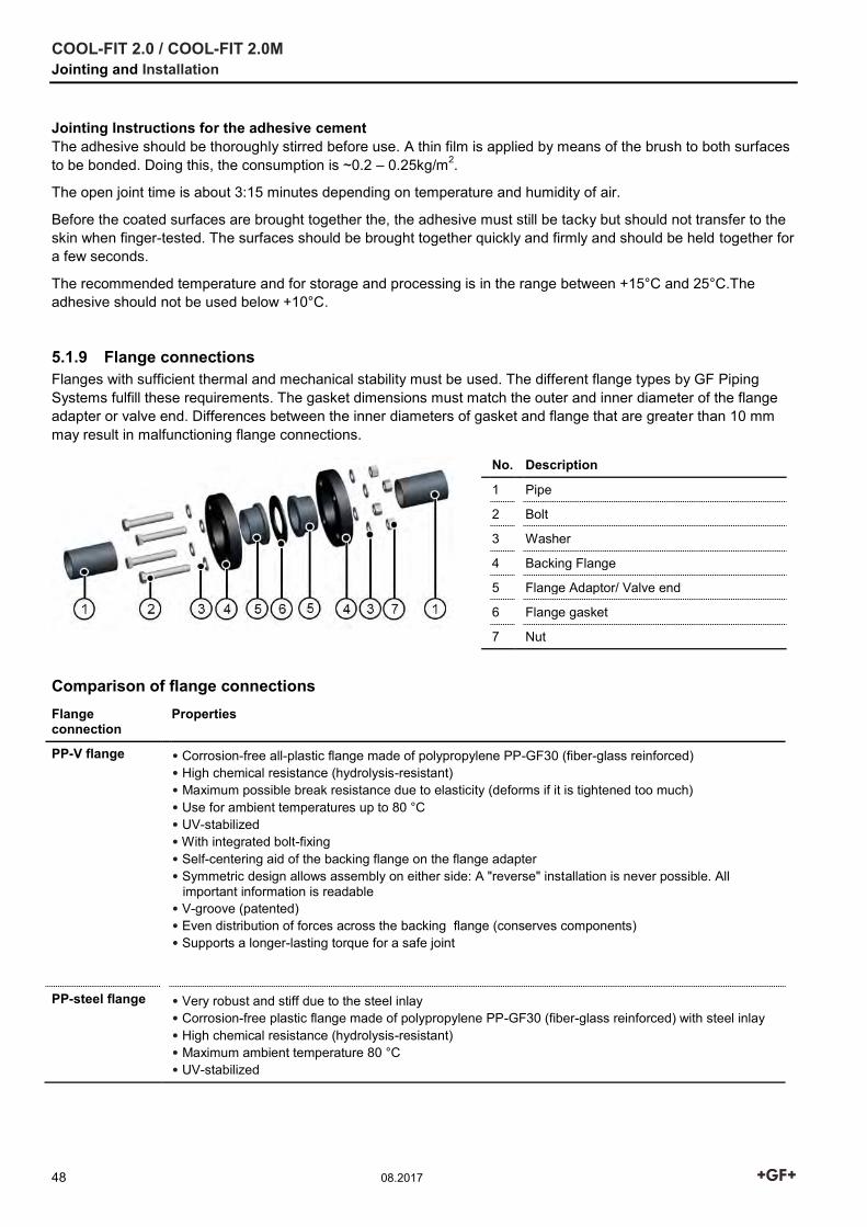
5.1.9 Flange connections Flanges with sufficient thermal and mechanical stability must be used. The different flange types by GF Piping Systems fulfill these requirements. The gasket dimensions must match the outer and inner diameter of the flange adapter or valve end. Differences between the inner diameters of gasket and flange that are greater than 10 mm may result in malfunctioning flange connections.
No. Description
1 Pipe
2 Bolt
3 Washer
4 Backing Flange
5 Flange Adaptor/ Valve end
6 Flange gasket
7 Nut
Comparison of flange connections Flange connection
Properties
PP-V flange • Corrosion-free all-plastic flange made of polypropylene PP-GF30 (fiber-glass reinforced) • High chemical resistance (hydrolysis-resistant) • Maximum possible break resistance due to elasticity (deforms if it is tightened too much) • Use for ambient temperatures up to 80 °C • UV-stabilized • With integrated bolt-fixing • Self-centering aid of the backing flange on the flange adapter • Symmetric design allows assembly on either side: A "reverse" installation is never possible. All important information is readable • V-groove (patented) • Even distribution of forces across the backing flange (conserves components) • Supports a longer-lasting torque for a safe joint
PP-steel flange • Very robust and stiff due to the steel inlay • Corrosion-free plastic flange made of polypropylene PP-GF30 (fiber-glass reinforced) with steel inlay • High chemical resistance (hydrolysis-resistant) • Maximum ambient temperature 80 °C • UV-stabilized
COOL-FIT 2.0 / COOL-FIT 2.0M Jointing and Installation
08.2017 49
Creating flange joints When executing flange joints, the following points should be noted:
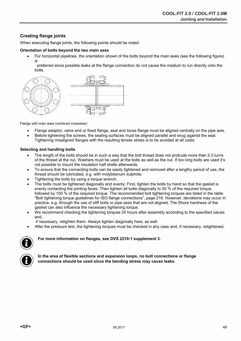
Orientation of bolts beyond the two main axes For horizontal pipelines, the orientation shown of the bolts beyond the main axes (see the following figure)
is preferred since possible leaks at the flange connection do not cause the medium to run directly onto the bolts.
Flange with main axes (centered crosswise)
Flange adaptor, valve end or fixed flange, seal and loose flange must be aligned centrally on the pipe axis. Before tightening the screws, the sealing surfaces must be aligned parallel and snug against the seal.
Tightening misaligned flanges with the resulting tensile stress is to be avoided at all costs.
Selecting and handling bolts The length of the bolts should be in such a way that the bolt thread does not protrude more than 2-3 turns
of the thread at the nut. Washers must be used at the bolts as well as the nut. If too long bolts are used it’s not possible to mount the insulation half shells afterwards.
To ensure that the connecting bolts can be easily tightened and removed after a lengthy period of use, the thread should be lubricated, e.g. with molybdenum sulphide.
Tightening the bolts by using a torque wrench. The bolts must be tightened diagonally and evenly: First, tighten the bolts by hand so that the gasket is
evenly contacting the jointing faces. Then tighten all bolts diagonally to 50 % of the required torque, followed by 100 % of the required torque. The recommended bolt tightening torques are listed in the table “Bolt tightening torque guidelines for ISO flange connections”, page 216. However, deviations may occur in practice, e.g. through the use of stiff bolts or pipe axes that are not aligned. The Shore hardness of the gasket can also influence the necessary tightening torque.
We recommend checking the tightening torques 24 hours after assembly according to the specified values and, if necessary, retighten them. Always tighten diagonally here, as well.
After the pressure test, the tightening torques must be checked in any case and, if necessary, retightened.
For more information on flanges, see DVS 2210-1 supplement 3.
In the area of flexible sections and expansion loops, no bolt connections or flange connections should be used since the bending stress may cause leaks.
COOL-FIT 2.0 / COOL-FIT 2.0M Jointing and Installation
50 08.2017
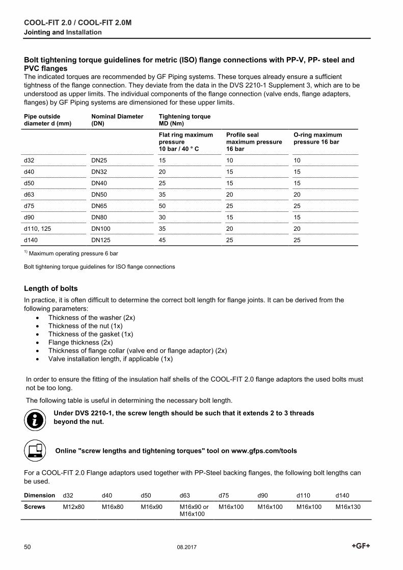
Bolt tightening torque guidelines for metric (ISO) flange connections with PP-V, PP- steel and PVC flanges The indicated torques are recommended by GF Piping systems. These torques already ensure a sufficient tightness of the flange connection. They deviate from the data in the DVS 2210-1 Supplement 3, which are to be understood as upper limits. The individual components of the flange connection (valve ends, flange adapters, flanges) by GF Piping systems are dimensioned for these upper limits.
Pipe outside diameter d (mm)
Nominal Diameter (DN)
Tightening torque MD (Nm)
Flat ring maximum pressure 10 bar / 40 ° C
Profile seal maximum pressure 16 bar
O-ring maximum pressure 16 bar
d32 DN25 15 10 10
d40 DN32 20 15 15
d50 DN40 25 15 15
d63 DN50 35 20 20
d75 DN65 50 25 25
d90 DN80 30 15 15
d110, 125 DN100 35 20 20
d140 DN125 45 25 25
1) Maximum operating pressure 6 bar Bolt tightening torque guidelines for ISO flange connections
Length of bolts In practice, it is often difficult to determine the correct bolt length for flange joints. It can be derived from the following parameters:
Thickness of the washer (2x) Thickness of the nut (1x) Thickness of the gasket (1x) Flange thickness (2x) Thickness of flange collar (valve end or flange adaptor) (2x) Valve installation length, if applicable (1x)
In order to ensure the fitting of the insulation half shells of the COOL-FIT 2.0 flange adaptors the used bolts must not be too long.
The following table is useful in determining the necessary bolt length.
Under DVS 2210-1, the screw length should be such that it extends 2 to 3 threads beyond the nut.
Online "screw lengths and tightening torques" tool on www.gfps.com/tools
For a COOL-FIT 2.0 Flange adaptors used together with PP-Steel backing flanges, the following bolt lengths can be used.
Dimension d32 d40 d50 d63 d75 d90 d110 d140
Screws M12x80 M16x80 M16x90 M16x90 or M16x100
M16x100 M16x100 M16x100 M16x130
COOL-FIT 2.0 / COOL-FIT 2.0M Jointing and Installation
08.2017 51
5.1.10 Installation fittings (for sensors) Transitions and threaded plastic fittings should first be screwed finger tight. The fittings are then screwed in using an appropriate tool until 1 or 2 threads remain visible.
GF Piping Systems recommends using PTFE tape to seal transitions and threaded plastic fittings. Alternatively, Henkel Tangit Uni-Lock or Loctite 55 thread seal or Loctite 5331 thread sealant gel can be used. Follow the manufacturer’s instructions. When using other sealants, you must check compatibility with the plastic used.
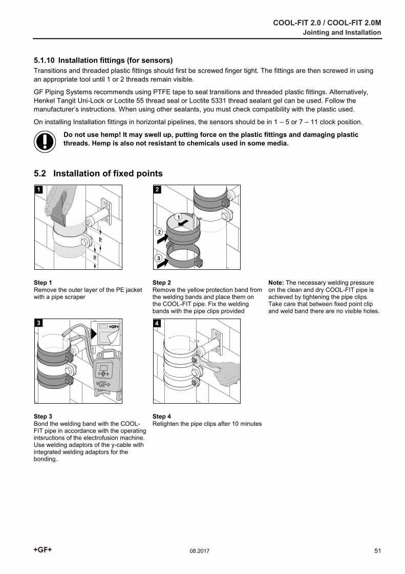
On installing Installation fittings in horizontal pipelines, the sensors should be in 1 – 5 or 7 – 11 clock position.
Do not use hemp! It may swell up, putting force on the plastic fittings and damaging plastic threads. Hemp is also not resistant to chemicals used in some media.
5.2 Installation of fixed points
Step 1 Remove the outer layer of the PE jacket with a pipe scraper
Step 2 Remove the yellow protection band from the welding bands and place them on the COOL-FIT pipe. Fix the welding bands with the pipe clips provided
Note: The necessary welding pressure on the clean and dry COOL-FIT pipe is achieved by tightening the pipe clips. Take care that between fixed point clip and weld band there are no visible holes.
Step 3 Bond the welding band with the COOL-FIT pipe in accordance with the operating intsructions of the electrofusion machine. Use welding adaptors of the y-cable with integrated welding adaptors for the bonding..
Step 4 Retighten the pipe clips after 10 minutes
1 2
3 4

COOL-FIT 2.0 / COOL-FIT 2.0M Jointing and Installation
52 08.2017
5.3 Pressure test Internal pressure test For internal pressure testing and commissioning, the same conditions apply for COOL-FIT 2.0 as for the non-insulated ecoFIT system (PE).
5.4 Internal pressure and leak testing 5.4.1 Introduction to the pressure test Overview of the various test methods Test methods Inner Pressure test Leakage test
Medium Water Gas1) Compressed air1 Gas/air (oil-free)
Type Incompressible Compressible Compressible Compressible
Test pressure (overpressure)
Pp (perm) or 0.85 Pp (perm)
Operating pressure 2 bar
Operating pressure 2 bar
0.5 bar
Potential risk during the pressure test
Low High High Low
Material All plastics ABS, PE PB, PE All plastics
Significance High: Proof of pressure resistance incl. impermeability to test medium
High: Proof of pressure resistance incl. impermeability to test medium
High: Proof of pressure resistance incl. impermeability to test medium
Low
1 Observe the applicable safety precautions. More information is available in DVS 2210-1 addendum 2.
A number of international and national standards and guidelines are available for leak and pressure tests. Therefore, it is often not easy to find the applicable test procedure and for example the test pressure.
The purpose of a pressure test is:
• Ensure the resistance to pressure of the pipeline, and
• Show the leak-tightness against the test medium
Usually, the internal pressure test is done as a water pressure test and only in exceptional cases (under consideration of special safety precautions) as a gas pressure test with air or nitrogen.
Water is an incompressible medium. In case of a leakage during the pressure test relative low energy is set free. Therefore the hazard potential is significantly lower compared to testing with a compressible medium like e.g. compressed air.
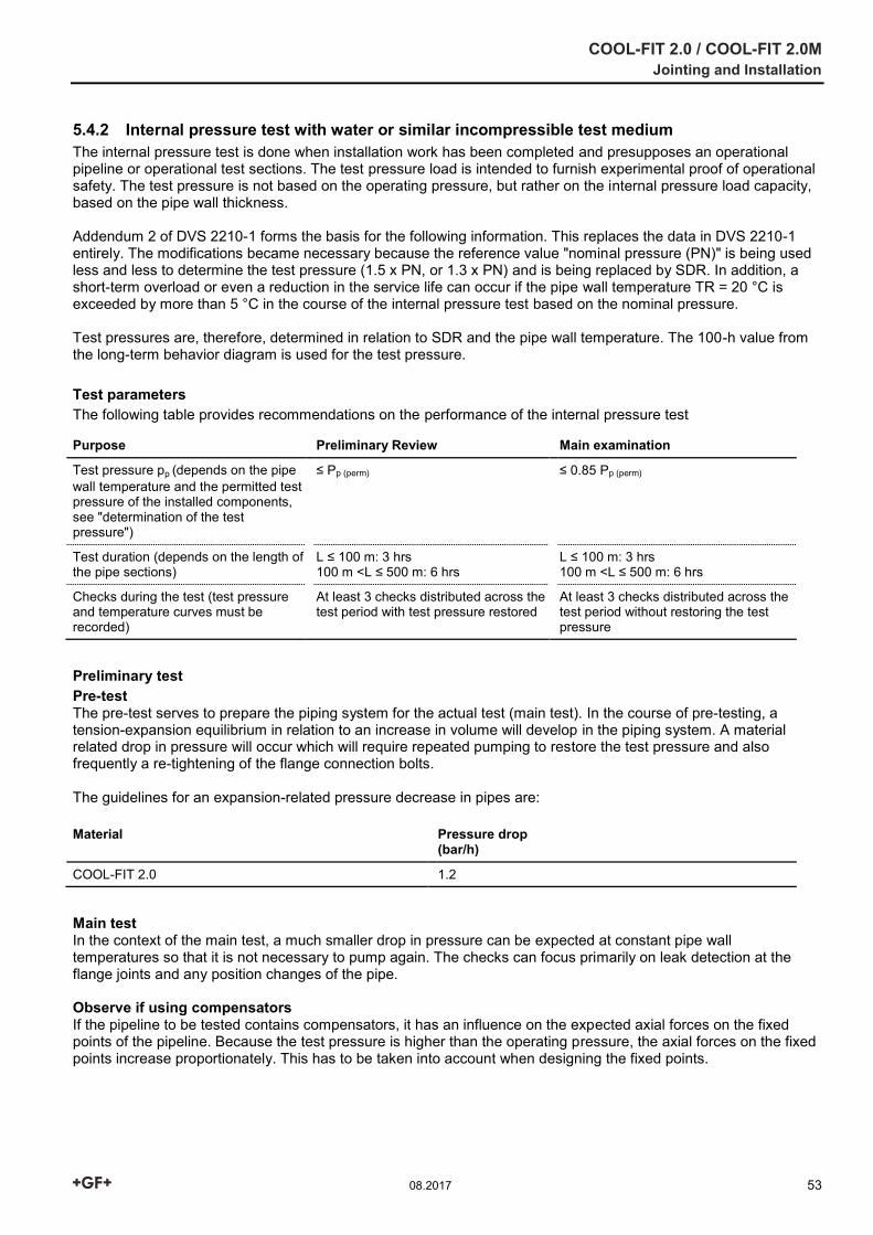
COOL-FIT 2.0 / COOL-FIT 2.0M Jointing and Installation
08.2017 53
5.4.2 Internal pressure test with water or similar incompressible test medium The internal pressure test is done when installation work has been completed and presupposes an operational pipeline or operational test sections. The test pressure load is intended to furnish experimental proof of operational safety. The test pressure is not based on the operating pressure, but rather on the internal pressure load capacity, based on the pipe wall thickness. Addendum 2 of DVS 2210-1 forms the basis for the following information. This replaces the data in DVS 2210-1 entirely. The modifications became necessary because the reference value "nominal pressure (PN)" is being used less and less to determine the test pressure (1.5 x PN, or 1.3 x PN) and is being replaced by SDR. In addition, a short-term overload or even a reduction in the service life can occur if the pipe wall temperature TR = 20 °C is exceeded by more than 5 °C in the course of the internal pressure test based on the nominal pressure. Test pressures are, therefore, determined in relation to SDR and the pipe wall temperature. The 100-h value from the long-term behavior diagram is used for the test pressure. Test parameters The following table provides recommendations on the performance of the internal pressure test
Purpose Preliminary Review Main examination
Test pressure pp (depends on the pipe wall temperature and the permitted test pressure of the installed components, see "determination of the test pressure")
≤ Pp (perm) ≤ 0.85 Pp (perm)
Test duration (depends on the length of the pipe sections)
L ≤ 100 m: 3 hrs 100 m <L ≤ 500 m: 6 hrs
L ≤ 100 m: 3 hrs 100 m <L ≤ 500 m: 6 hrs
Checks during the test (test pressure and temperature curves must be recorded)
At least 3 checks distributed across the test period with test pressure restored
At least 3 checks distributed across the test period without restoring the test pressure
Preliminary test Pre-test The pre-test serves to prepare the piping system for the actual test (main test). In the course of pre-testing, a tension-expansion equilibrium in relation to an increase in volume will develop in the piping system. A material related drop in pressure will occur which will require repeated pumping to restore the test pressure and also frequently a re-tightening of the flange connection bolts. The guidelines for an expansion-related pressure decrease in pipes are: Material Pressure drop
(bar/h)
COOL-FIT 2.0 1.2
Main test In the context of the main test, a much smaller drop in pressure can be expected at constant pipe wall temperatures so that it is not necessary to pump again. The checks can focus primarily on leak detection at the flange joints and any position changes of the pipe. Observe if using compensators If the pipeline to be tested contains compensators, it has an influence on the expected axial forces on the fixed points of the pipeline. Because the test pressure is higher than the operating pressure, the axial forces on the fixed points increase proportionately. This has to be taken into account when designing the fixed points.
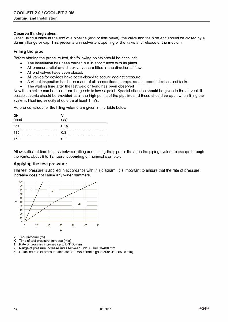
COOL-FIT 2.0 / COOL-FIT 2.0M Jointing and Installation
54 08.2017
Observe if using valves When using a valve at the end of a pipeline (end or final valve), the valve and the pipe end should be closed by a dummy flange or cap. This prevents an inadvertent opening of the valve and release of the medium. Filling the pipe Before starting the pressure test, the following points should be checked:
The installation has been carried out in accordance with its plans. All pressure relief and check valves are fitted in the direction of flow. All end valves have been closed. All valves for devices have been closed to secure against pressure. A visual inspection has been made of all connections, pumps, measurement devices and tanks. The waiting time after the last weld or bond has been observed
Now the pipeline can be filled from the geodetic lowest point. Special attention should be given to the air vent. If possible, vents should be provided at all the high points of the pipeline and these should be open when filling the system. Flushing velocity should be at least 1 m/s.
Reference values for the filling volume are given in the table below
DN (mm)
V (l/s)
≤ 90 0.15
110 0.3
160 0.7
Allow sufficient time to pass between filling and testing the pipe for the air in the piping system to escape through the vents: about 6 to 12 hours, depending on nominal diameter.
Applying the test pressure The test pressure is applied in accordance with this diagram. It is important to ensure that the rate of pressure increase does not cause any water hammers.
Y Test pressure (%) X Time of test pressure increase (min) 1) Rate of pressure increase up to DN100 mm 2) Range of pressure increase rates between DN100 and DN400 mm 3) Guideline rate of pressure increase for DN500 and higher: 500/DN (bar/10 min)
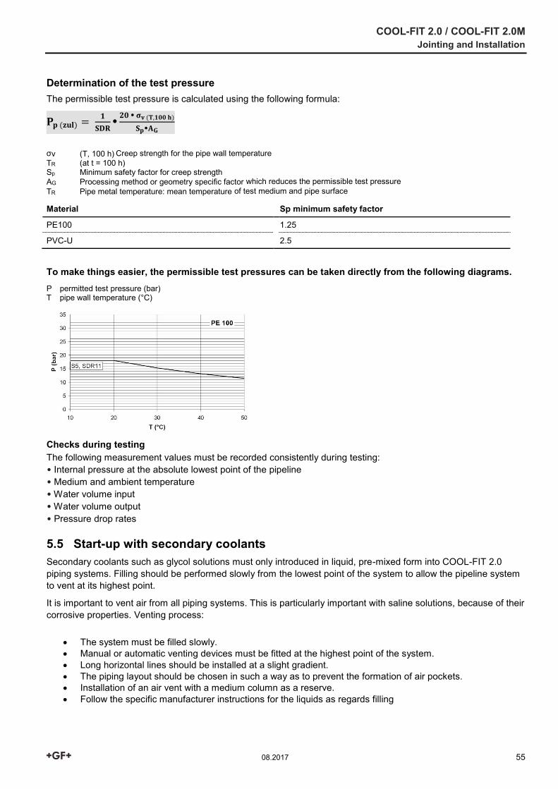
COOL-FIT 2.0 / COOL-FIT 2.0M Jointing and Installation
08.2017 55
Determination of the test pressure The permissible test pressure is calculated using the following formula:
𝐏𝐩 (𝐳𝐮𝐥) = 𝟏
𝐒𝐃𝐑
𝟐𝟎 𝛔𝐯 (𝐓,𝟏𝟎𝟎 𝐡)
𝐒𝐩𝐀𝐆
σv (T, 100 h) Creep strength for the pipe wall temperature TR (at t = 100 h) Sp Minimum safety factor for creep strength AG Processing method or geometry specific factor which reduces the permissible test pressure TR Pipe metal temperature: mean temperature of test medium and pipe surface
Material Sp minimum safety factor
PE100 1.25
PVC-U 2.5
To make things easier, the permissible test pressures can be taken directly from the following diagrams. P permitted test pressure (bar) T pipe wall temperature (°C)
Checks during testing The following measurement values must be recorded consistently during testing: • Internal pressure at the absolute lowest point of the pipeline • Medium and ambient temperature • Water volume input • Water volume output • Pressure drop rates
5.5 Start-up with secondary coolants Secondary coolants such as glycol solutions must only introduced in liquid, pre-mixed form into COOL-FIT 2.0 piping systems. Filling should be performed slowly from the lowest point of the system to allow the pipeline system to vent at its highest point.
It is important to vent air from all piping systems. This is particularly important with saline solutions, because of their corrosive properties. Venting process:
The system must be filled slowly. Manual or automatic venting devices must be fitted at the highest point of the system. Long horizontal lines should be installed at a slight gradient. The piping layout should be chosen in such a way as to prevent the formation of air pockets. Installation of an air vent with a medium column as a reserve. Follow the specific manufacturer instructions for the liquids as regards filling
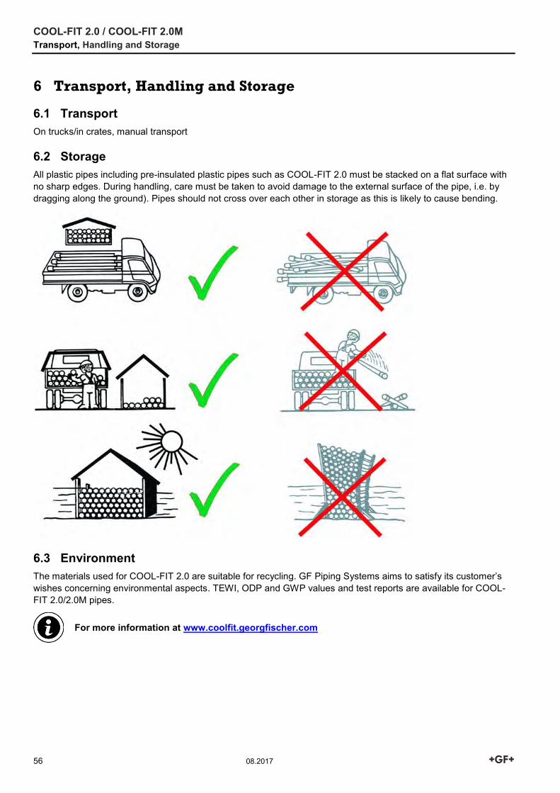
COOL-FIT 2.0 / COOL-FIT 2.0M Transport, Handling and Storage
56 08.2017
6 Transport, Handling and Storage
6.1 Transport On trucks/in crates, manual transport
6.2 Storage All plastic pipes including pre-insulated plastic pipes such as COOL-FIT 2.0 must be stacked on a flat surface with no sharp edges. During handling, care must be taken to avoid damage to the external surface of the pipe, i.e. by dragging along the ground). Pipes should not cross over each other in storage as this is likely to cause bending.
6.3 Environment The materials used for COOL-FIT 2.0 are suitable for recycling. GF Piping Systems aims to satisfy its customer’s wishes concerning environmental aspects. TEWI, ODP and GWP values and test reports are available for COOL-FIT 2.0/2.0M pipes.
For more information at www.coolfit.georgfischer.com