Embed Size (px)
Citation preview
Planetary gears.Standard series & custom engineered solutions.
2 32 3
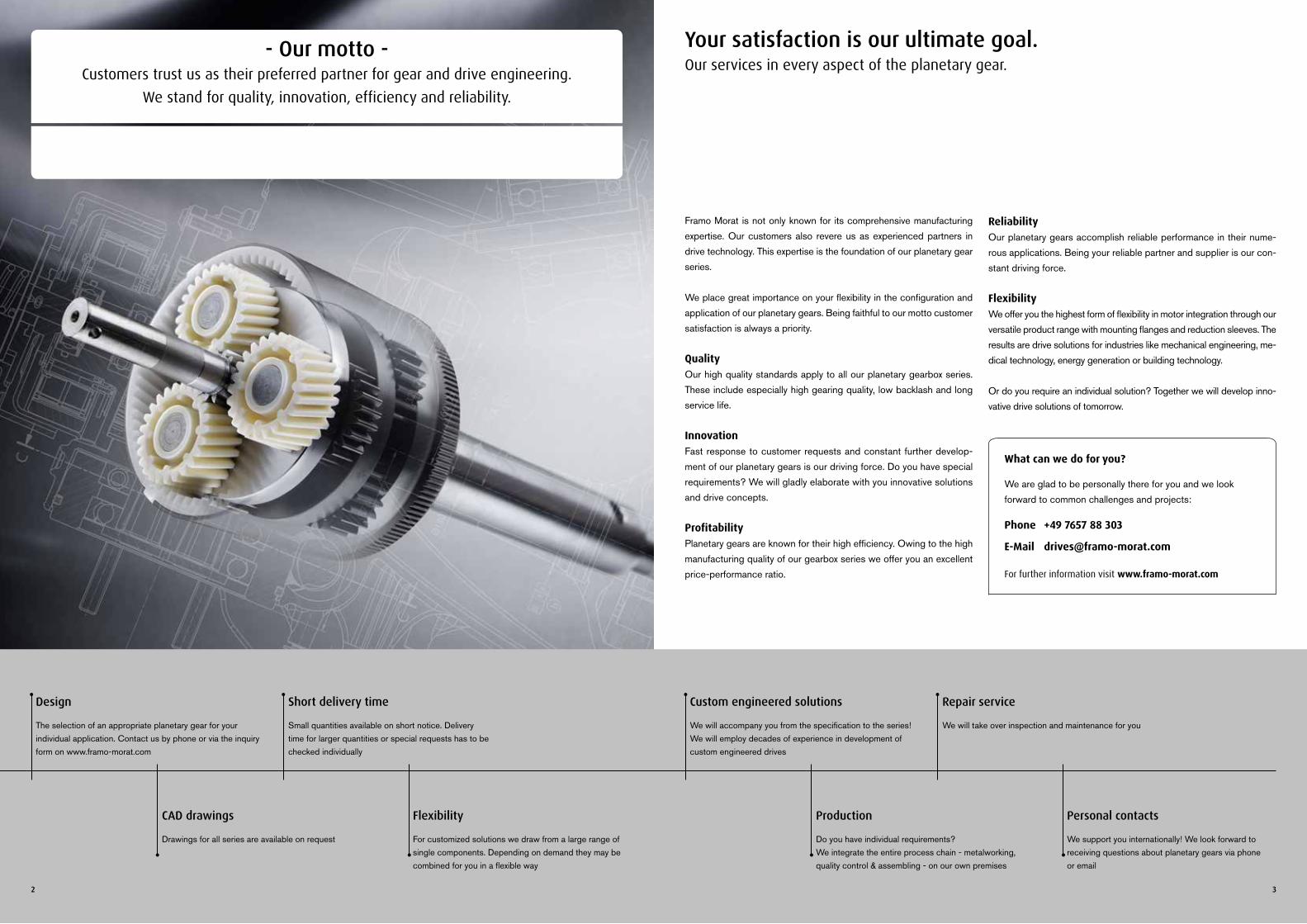
Framo Morat is not only known for its comprehensive manufacturing expertise. Our customers also revere us as experienced partners in drive technology. This expertise is the foundation of our planetary gear series.
We place great importance on your flexibility in the configuration and application of our planetary gears. Being faithful to our motto customer satisfaction is always a priority.
QualityOur high quality standards apply to all our planetary gearbox series. These include especially high gearing quality, low backlash and long service life.
InnovationFast response to customer requests and constant further develop-ment of our planetary gears is our driving force. Do you have special requirements? We will gladly elaborate with you innovative solutions and drive concepts. ProfitabilityPlanetary gears are known for their high efficiency. Owing to the high manufacturing quality of our gearbox series we offer you an excellent price-performance ratio.
ReliabilityOur planetary gears accomplish reliable performance in their nume-rous applications. Being your reliable partner and supplier is our con-stant driving force.
FlexibilityWe offer you the highest form of flexibility in motor integration through our versatile product range with mounting flanges and reduction sleeves. The results are drive solutions for industries like mechanical engineering, me-dical technology, energy generation or building technology.
Or do you require an individual solution? Together we will develop inno-vative drive solutions of tomorrow.
Your satisfaction is our ultimate goal.Our services in every aspect of the planetary gear.
Design
The selection of an appropriate planetary gear for your individual application. Contact us by phone or via the inquiry form on www.framo-morat.com
Short delivery time
Small quantities available on short notice. Delivery time for larger quantities or special requests has to be checked individually
CAD drawings
Drawings for all series are available on request
Flexibility
For customized solutions we draw from a large range of single components. Depending on demand they may be combined for you in a flexible way
Custom engineered solutions
We will accompany you from the specification to the series! We will employ decades of experience in development of custom engineered drives
Repair service
We will take over inspection and maintenance for you
Production
Do you have individual requirements? We integrate the entire process chain - metalworking, quality control & assembling - on our own premises
Personal contacts
We support you internationally! We look forward to receiving questions about planetary gears via phone or email
- Our motto -Customers trust us as their preferred partner for gear and drive engineering.
We stand for quality, innovation, efficiency and reliability.
What can we do for you?
We are glad to be personally there for you and we look forward to common challenges and projects:
Phone +49 7657 88 303
E-Mail [email protected]
For further information visit www.framo-morat.com
4 5
OverviewOverview
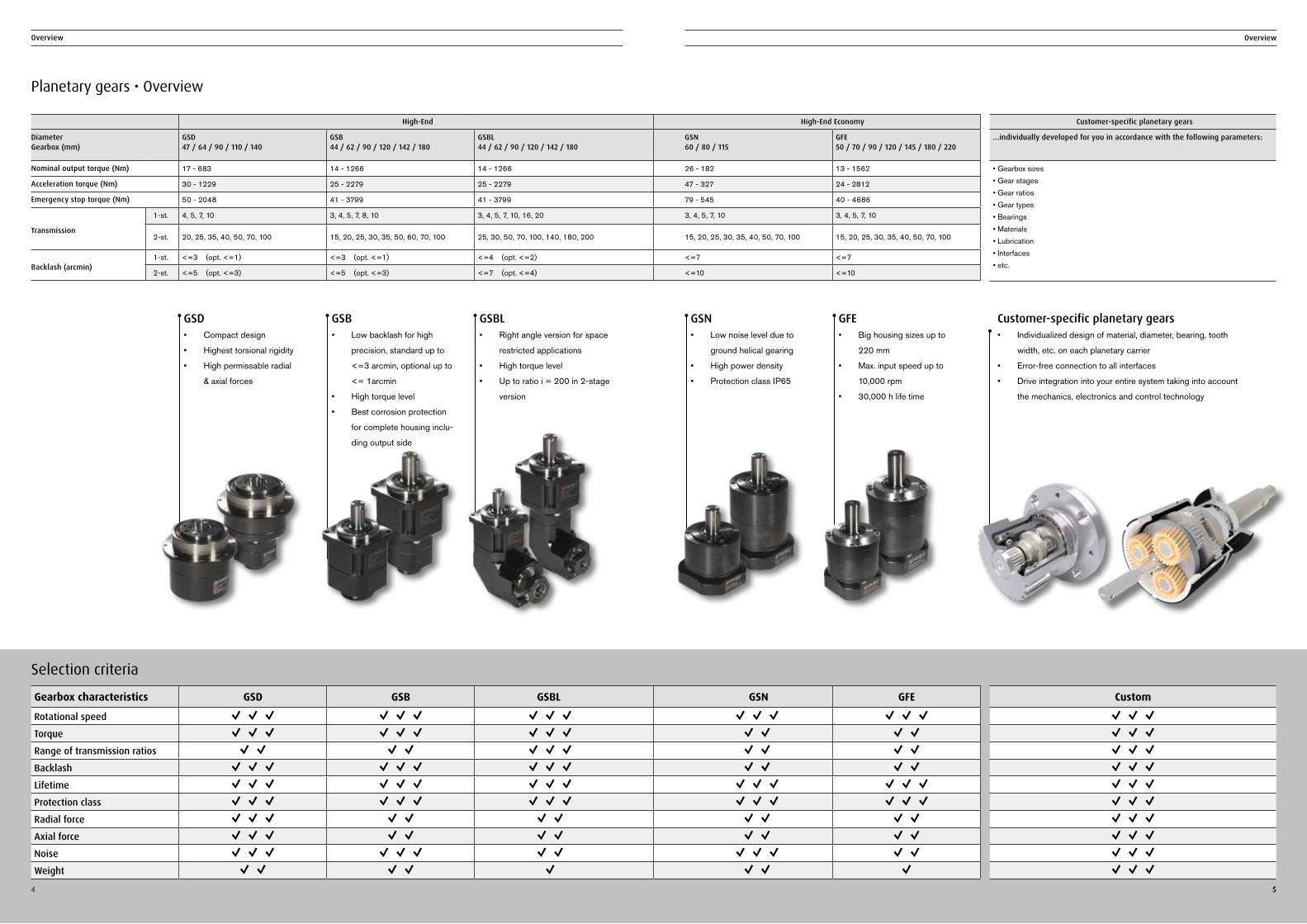
Planetary gears • Overview
5
GFE• Big housing sizes up to
220 mm
• Max. input speed up to
10,000 rpm
• 30,000 h life time
GSN• Low noise level due to
ground helical gearing
• High power density
• Protection class IP65
GSB• Low backlash for high
precision, standard up to
<=3 arcmin, optional up to
<= 1arcmin
• High torque level
• Best corrosion protection
for complete housing inclu-
ding output side
GSBL• Right angle version for space
restricted applications
• High torque level
• Up to ratio i = 200 in 2-stage
version
GSD• Compact design
• Highest torsional rigidity
• High permissable radial
& axial forces
Selection criteria
Gearbox characteristics GSD GSB GSBL GSN GFE
Rotational speed ✓ ✓ ✓ ✓ ✓ ✓ ✓ ✓ ✓ ✓ ✓ ✓ ✓ ✓ ✓Torque ✓ ✓ ✓ ✓ ✓ ✓ ✓ ✓ ✓ ✓ ✓ ✓ ✓Range of transmission ratios ✓ ✓ ✓ ✓ ✓ ✓ ✓ ✓ ✓ ✓ ✓Backlash ✓ ✓ ✓ ✓ ✓ ✓ ✓ ✓ ✓ ✓ ✓ ✓ ✓Lifetime ✓ ✓ ✓ ✓ ✓ ✓ ✓ ✓ ✓ ✓ ✓ ✓ ✓ ✓ ✓Protection class ✓ ✓ ✓ ✓ ✓ ✓ ✓ ✓ ✓ ✓ ✓ ✓ ✓ ✓ ✓Radial force ✓ ✓ ✓ ✓ ✓ ✓ ✓ ✓ ✓ ✓ ✓Axial force ✓ ✓ ✓ ✓ ✓ ✓ ✓ ✓ ✓ ✓ ✓Noise ✓ ✓ ✓ ✓ ✓ ✓ ✓ ✓ ✓ ✓ ✓ ✓ ✓Weight ✓ ✓ ✓ ✓ ✓ ✓ ✓ ✓
High-End High-End Economy
Diameter Gearbox (mm)
GSD 47 / 64 / 90 / 110 / 140
GSB 44 / 62 / 90 / 120 / 142 / 180
GSBL 44 / 62 / 90 / 120 / 142 / 180
GSN 60 / 80 / 115
GFE 50 / 70 / 90 / 120 / 145 / 180 / 220
Nominal output torque (Nm) 17 - 683 14 - 1266 14 - 1266 26 - 182 13 - 1562
Acceleration torque (Nm) 30 - 1229 25 - 2279 25 - 2279 47 - 327 24 - 2812
Emergency stop torque (Nm) 50 - 2048 41 - 3799 41 - 3799 79 - 545 40 - 4686
Transmission
1-st. 4, 5, 7, 10 3, 4, 5, 7, 8, 10 3, 4, 5, 7, 10, 16, 20 3, 4, 5, 7, 10 3, 4, 5, 7, 10
2-st. 20, 25, 35, 40, 50, 70, 100 15, 20, 25, 30, 35, 50, 60, 70, 100 25, 30, 50, 70, 100, 140, 180, 200 15, 20, 25, 30, 35, 40, 50, 70, 100 15, 20, 25, 30, 35, 40, 50, 70, 100
Backlash (arcmin)1-st. <=3 (opt. <=1) <=3 (opt. <=1) <=4 (opt. <=2) <=7 <=7
2-st. <=5 (opt. <=3) <=5 (opt. <=3) <=7 (opt. <=4) <=10 <=10
Customer-specific planetary gears• Individualized design of material, diameter, bearing, tooth
width, etc. on each planetary carrier
• Error-free connection to all interfaces
• Drive integration into your entire system taking into account
the mechanics, electronics and control technology
Customer-specific planetary gears
...individually developed for you in accordance with the following parameters:
• Gearbox sizes • Gear stages • Gear ratios • Gear types • Bearings • Materials • Lubrication • Interfaces • etc.
Custom
✓ ✓ ✓✓ ✓ ✓✓ ✓ ✓✓ ✓ ✓✓ ✓ ✓✓ ✓ ✓✓ ✓ ✓✓ ✓ ✓✓ ✓ ✓✓ ✓ ✓
The G-series.Low-backlash planetary gears - compact and highly precise.
6 7
The G-series
G-series - High-End & High-End Economy range
The G-series includes the high-end gearbox lines GSD (flange gear), GSB (inline) and GSBL (angle gear) as well as the high-end economy GSN and GFE lines.
Particularly suitable applications for the G-series are those which place the highest demands on positioning accuracy, operating nois-es, running smoothness, bending rigidity and transmitted torque. The G-series is designed to meet the highest production require-ments—all planetary gear sets are equipped with precision ground
helical gearing, single-piece planetary carriers and full needle bear-ings. Resolutely applied quality assurance measures consistently ensure that all high quality requirements are fulfilled at all times.
Particularly in the case of medium and large-volume projects, cus-tom adaptations can also be made. We would be happy to develop your customized gearbox in accordance with your individual specifi-cations.
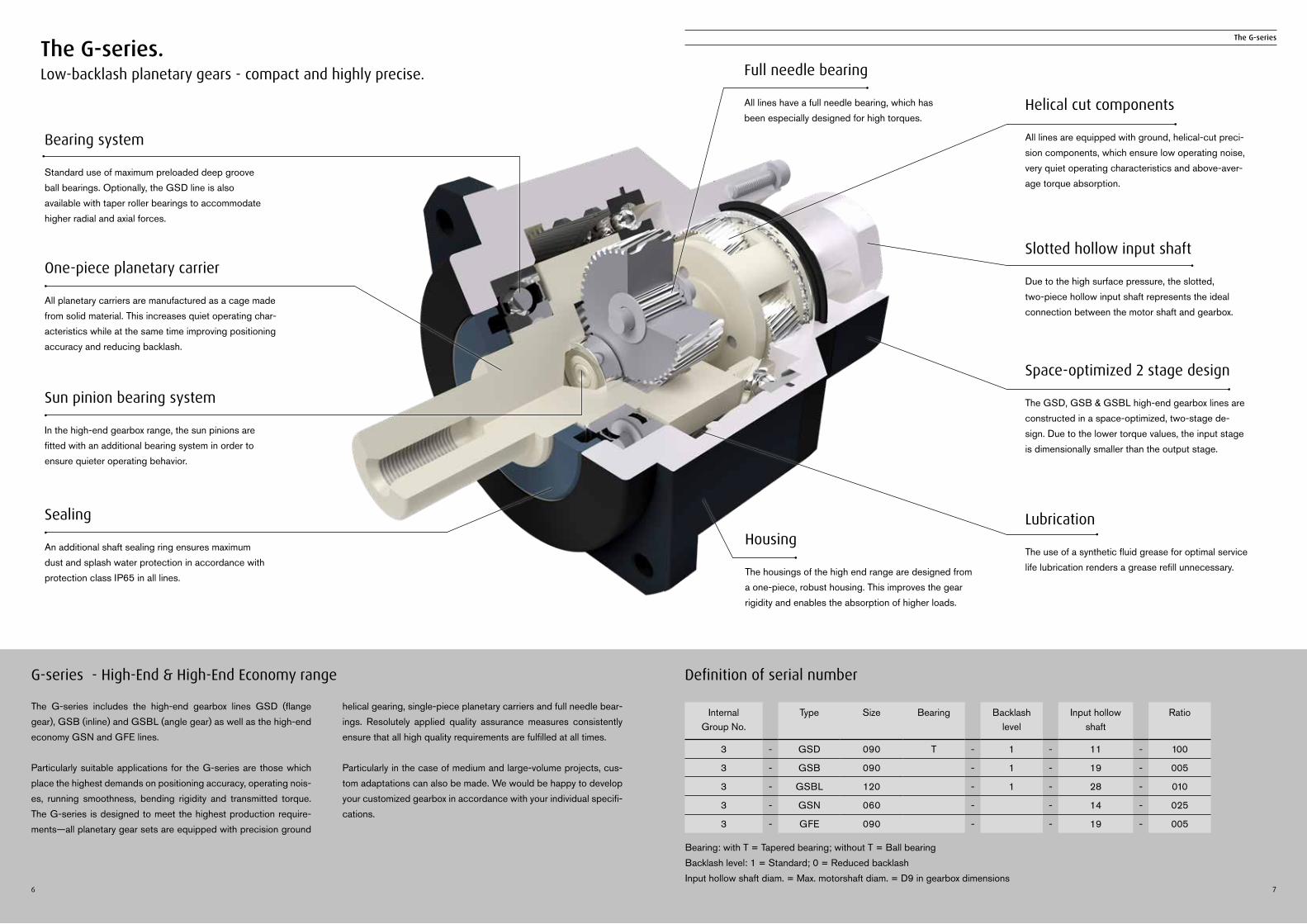
Bearing: with T = Tapered bearing; without T = Ball bearingBacklash level: 1 = Standard; 0 = Reduced backlashInput hollow shaft diam. = Max. motorshaft diam. = D9 in gearbox dimensions
Definition of serial number
Bearing system
Standard use of maximum preloaded deep groove ball bearings. Optionally, the GSD line is also available with taper roller bearings to accommodate higher radial and axial forces.
Helical cut components
All lines are equipped with ground, helical-cut preci-sion components, which ensure low operating noise, very quiet operating characteristics and above-aver-age torque absorption.
Full needle bearing
All lines have a full needle bearing, which has been especially designed for high torques.
One-piece planetary carrier
All planetary carriers are manufactured as a cage made from solid material. This increases quiet operating char-acteristics while at the same time improving positioning accuracy and reducing backlash.
Lubrication
The use of a synthetic fluid grease for optimal service life lubrication renders a grease refill unnecessary.
Sun pinion bearing system
In the high-end gearbox range, the sun pinions are fitted with an additional bearing system in order to ensure quieter operating behavior.
Slotted hollow input shaft
Due to the high surface pressure, the slotted, two-piece hollow input shaft represents the ideal connection between the motor shaft and gearbox.
Sealing
An additional shaft sealing ring ensures maximum dust and splash water protection in accordance with protection class IP65 in all lines.
Space-optimized 2 stage design
The GSD, GSB & GSBL high-end gearbox lines are constructed in a space-optimized, two-stage de-sign. Due to the lower torque values, the input stage is dimensionally smaller than the output stage.
Housing
The housings of the high end range are designed from a one-piece, robust housing. This improves the gear rigidity and enables the absorption of higher loads.
Internal Group No.
Type Size Bearing Backlash level
Input hollow shaft
Ratio
3 - GSD 090 T - 1 - 11 - 100
3 - GSB 090 - 1 - 19 - 005
3 - GSBL 120 - 1 - 28 - 010
3 - GSN 060 - - 14 - 025
3 - GFE 090 - - 19 - 005
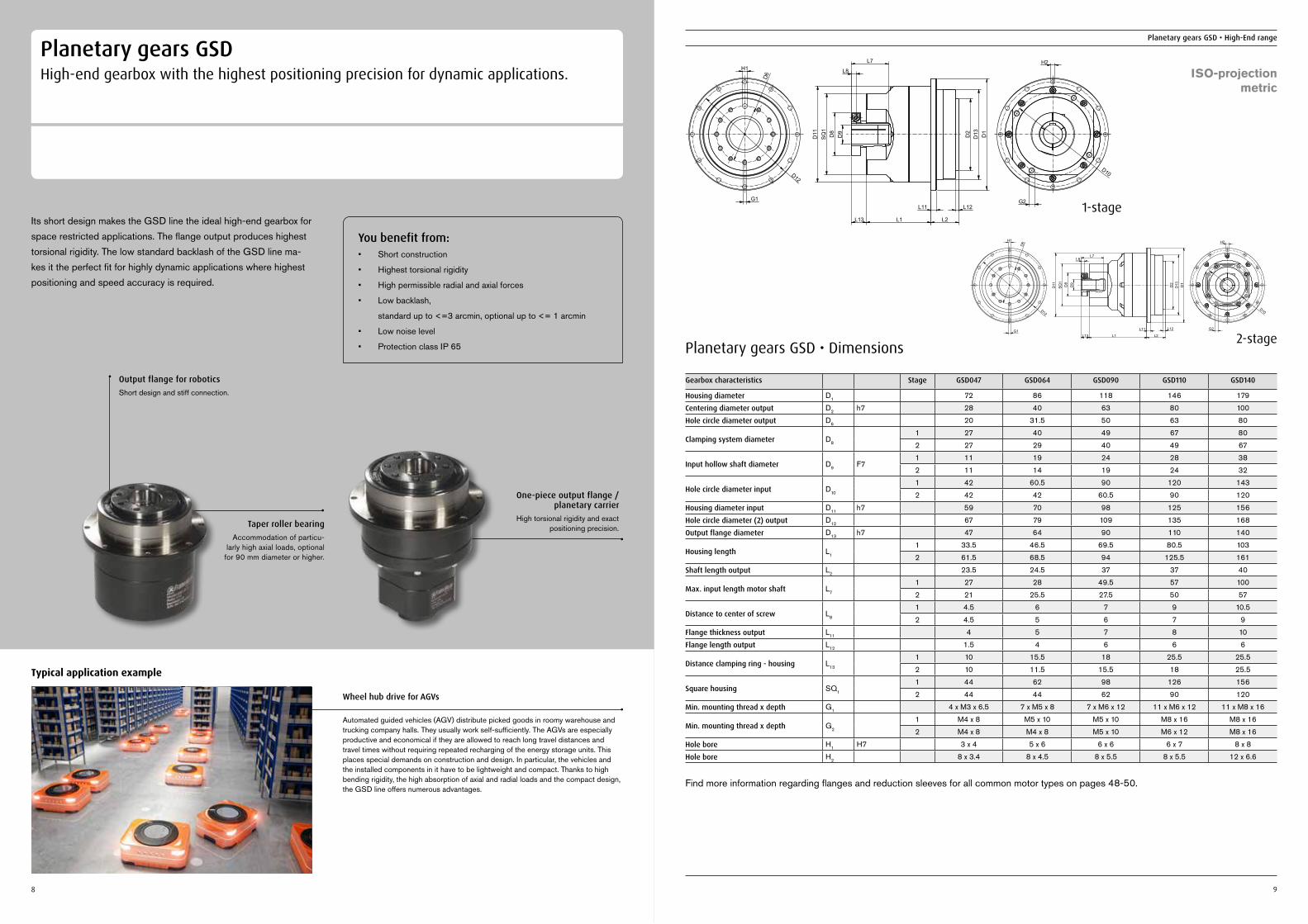
Planetary gears GSDHigh-end gearbox with the highest positioning precision for dynamic applications.
Its short design makes the GSD line the ideal high-end gearbox for space restricted applications. The flange output produces highest torsional rigidity. The low standard backlash of the GSD line ma-kes it the perfect fit for highly dynamic applications where highest positioning and speed accuracy is required.
You benefit from:• Short construction
• Highest torsional rigidity
• High permissible radial and axial forces
• Low backlash,
standard up to <=3 arcmin, optional up to <= 1 arcmin
• Low noise level
• Protection class IP 65
Wheel hub drive for AGVs
Automated guided vehicles (AGV) distribute picked goods in roomy warehouse and trucking company halls. They usually work self-sufficiently. The AGVs are especially productive and economical if they are allowed to reach long travel distances and travel times without requiring repeated recharging of the energy storage units. This places special demands on construction and design. In particular, the vehicles and the installed components in it have to be lightweight and compact. Thanks to high bending rigidity, the high absorption of axial and radial loads and the compact design, the GSD line offers numerous advantages.
Typical application example
Output flange for roboticsShort design and stiff connection.
Taper roller bearing Accommodation of particu-
larly high axial loads, optional for 90 mm diameter or higher.
8
Planetary gears GSD • High-End range
9
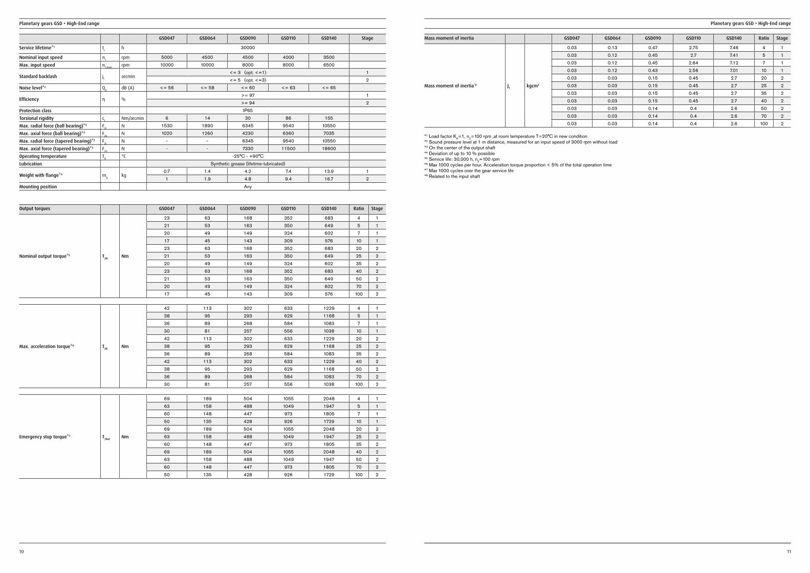
Planetary gears GSD • Dimensions
Gearbox characteristics Stage GSD047 GSD064 GSD090 GSD110 GSD140
Housing diameter D1 72 86 118 146 179
Centering diameter output D2 h7 28 40 63 80 100
Hole circle diameter output D6 20 31.5 50 63 80
Clamping system diameter D8
1 27 40 49 67 80
2 27 29 40 49 67
Input hollow shaft diameter D9 F71 11 19 24 28 38
2 11 14 19 24 32
Hole circle diameter input D10
1 42 60.5 90 120 143
2 42 42 60.5 90 120
Housing diameter input D11 h7 59 70 98 125 156
Hole circle diameter (2) output D12 67 79 109 135 168
Output flange diameter D13 h7 47 64 90 110 140
Housing length L1
1 33.5 46.5 69.5 80.5 103
2 61.5 68.5 94 125.5 161
Shaft length output L2 23.5 24.5 37 37 40
Max. input length motor shaft L7
1 27 28 49.5 57 100
2 21 25.5 27.5 50 57
Distance to center of screw L8
1 4.5 6 7 9 10.5
2 4.5 5 6 7 9
Flange thickness output L11 4 5 7 8 10
Flange length output L12 1.5 4 6 6 6
Distance clamping ring - housing L13
1 10 15.5 18 25.5 25.5
2 10 11.5 15.5 18 25.5
Square housing SQ1
1 44 62 98 126 156
2 44 44 62 90 120
Min. mounting thread x depth G1 4 x M3 x 6.5 7 x M5 x 8 7 x M6 x 12 11 x M6 x 12 11 x M8 x 16
Min. mounting thread x depth G2
1 M4 x 8 M5 x 10 M5 x 10 M8 x 16 M8 x 16
2 M4 x 8 M4 x 8 M5 x 10 M6 x 12 M8 x 16
Hole bore H1 H7 3 x 4 5 x 6 6 x 6 6 x 7 8 x 8
Hole bore H2 8 x 3.4 8 x 4.5 8 x 5.5 8 x 5.5 12 x 6.6
Find more information regarding flanges and reduction sleeves for all common motor types on pages 48-50.
H1
D6
D12
G1
D11
SQ
1D
8D
9
L7
L8
L1L13
L11
L2
L12
D2
D13 D1
H2
D10
G2 1-stage
D13
D11
L12
L2L1L13
D2
L11
D1
SQ1
D9D8
L7L8
G2
H2
D10
H1
D12
D6
G1
2-stage
ISO-projectionmetric
One-piece output flange / planetary carrier
High torsional rigidity and exact positioning precision.
Planetary gears GSD • High-End range
10
Planetary gears GSD • High-End range
11
Output torques GSD047 GSD064 GSD090 GSD110 GSD140 Ratio Stage
Nominal output torque*5 T2N Nm
23 63 168 352 683 4 121 53 163 350 649 5 120 49 149 324 602 7 117 45 143 309 576 10 123 63 168 352 683 20 221 53 163 350 649 25 220 49 149 324 602 35 223 63 168 352 683 40 221 53 163 350 649 50 220 49 149 324 602 70 217 45 143 309 576 100 2
Max. acceleration torque*6 T2B Nm
42 113 302 633 1229 4 138 95 293 629 1168 5 136 89 268 584 1083 7 130 81 257 556 1038 10 142 113 302 633 1229 20 238 95 293 629 1168 25 236 89 268 584 1083 35 242 113 302 633 1229 40 238 95 293 629 1168 50 236 89 268 584 1083 70 230 81 257 556 1038 100 2
Mass moment of inertia GSD047 GSD064 GSD090 GSD110 GSD140 Ratio Stage
Mass moment of inertia*8 J1 kgcm2
0.03 0.13 0.47 2.75 7.46 4 10.03 0.12 0.45 2.7 7.41 5 10.03 0.12 0.45 2.64 7.12 7 10.03 0.12 0.43 2.56 7.01 10 10.03 0.03 0.15 0.45 2.7 20 20.03 0.03 0.15 0.45 2.7 25 20.03 0.03 0.15 0.45 2.7 35 20.03 0.03 0.15 0.45 2.7 40 20.03 0.03 0.14 0.4 2.6 50 20.03 0.03 0.14 0.4 2.6 70 20.03 0.03 0.14 0.4 2.6 100 2
Emergency stop torque*7 T2Not Nm
69 189 504 1055 2048 4 163 158 488 1049 1947 5 160 148 447 973 1805 7 150 135 428 926 1729 10 169 189 504 1055 2048 20 263 158 488 1049 1947 25 260 148 447 973 1805 35 269 189 504 1055 2048 40 263 158 488 1049 1947 50 260 148 447 973 1805 70 250 135 428 926 1729 100 2
GSD047 GSD064 GSD090 GSD110 GSD140 Stage
Service lifetime*1 tL h 30000
Nominal input speed n1 rpm 5000 4500 4500 4000 3500
Max. input speed n1 max. rpm 10000 10000 8000 8000 6500
Standard backlash jt arcmin<= 3 (opt. <=1) 1<= 5 (opt. <=3) 2
Noise level*2 Qg dB (A) <= 56 <= 58 <= 60 <= 63 <= 65
Efficiency ƞ %>= 97 1>= 94 2
Protection class IP65
Torsional rigidity ct Nm/arcmin 6 14 30 86 155
Max. radial force (ball bearing)*3 F2r N 1530 1890 6345 9540 10550
Max. axial force (ball bearing)*3 F2a N 1020 1260 4230 6360 7035
Max. radial force (tapered bearing)*3 F2r N - - 6345 9540 10550
Max. axial force (tapered bearing)*3 F2a N - - 7330 11500 18600
Operating temperature TB °C -25°C - +90°C
Lubrication Synthetic grease (lifetime-lubricated)
Weight with flange*4 mg kg0.7 1.4 4.2 7.4 13.9 11 1.9 4.8 9.4 16.7 2
Mounting position Any
*1 Load factor KA=1, n2=100 rpm ,at room temperature T=20°C in new condition*2 Sound pressure level at 1 m distance, measured for an input speed of 3000 rpm without load*3 On the center of the output shaft*4 Deviation of up to 10 % possible*5 Service life: 30,000 h, n2=100 rpm*6 Max 1000 cycles per hour. Acceleration torque proportion < 5% of the total operation time*7 Max 1000 cycles over the gear service life*8 Related to the input shaft
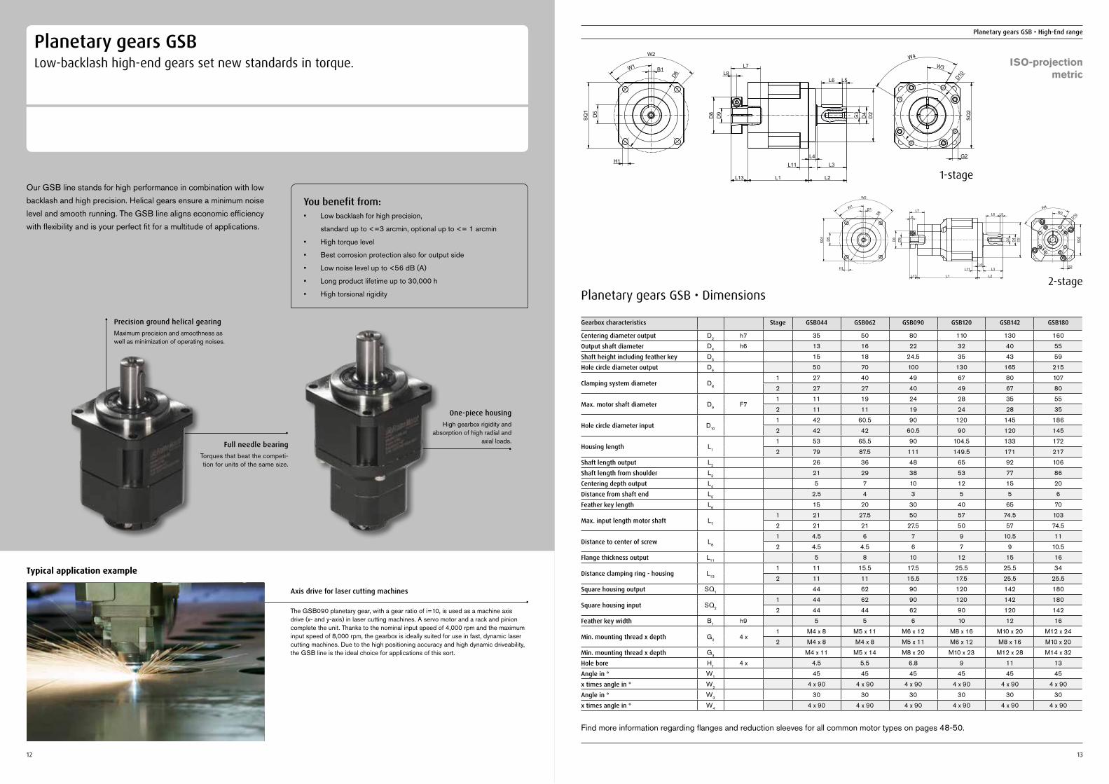
Planetary gears GSBLow-backlash high-end gears set new standards in torque.
Our GSB line stands for high performance in combination with low backlash and high precision. Helical gears ensure a minimum noise level and smooth running. The GSB line aligns economic efficiency with flexibility and is your perfect fit for a multitude of applications.
You benefit from:• Low backlash for high precision,
standard up to <=3 arcmin, optional up to <= 1 arcmin
• High torque level
• Best corrosion protection also for output side
• Low noise level up to <56 dB (A)
• Long product lifetime up to 30,000 h
• High torsional rigidity
Axis drive for laser cutting machines
The GSB090 planetary gear, with a gear ratio of i=10, is used as a machine axis drive (x- and y-axis) in laser cutting machines. A servo motor and a rack and pinion complete the unit. Thanks to the nominal input speed of 4,000 rpm and the maximum input speed of 8,000 rpm, the gearbox is ideally suited for use in fast, dynamic laser cutting machines. Due to the high positioning accuracy and high dynamic driveability, the GSB line is the ideal choice for applications of this sort.
Typical application example
Precision ground helical gearingMaximum precision and smoothness as well as minimization of operating noises.
Full needle bearing Torques that beat the competi-tion for units of the same size.
12 13
Planetary gears GSB • High-End range
Planetary gears GSB • Dimensions
Gearbox characteristics Stage GSB044 GSB062 GSB090 GSB120 GSB142 GSB180
Centering diameter output D2 h7 35 50 80 110 130 160
Output shaft diameter D4 h6 13 16 22 32 40 55
Shaft height including feather key D5 15 18 24.5 35 43 59
Hole circle diameter output D6 50 70 100 130 165 215
Clamping system diameter D8
1 27 40 49 67 80 107
2 27 27 40 49 67 80
Max. motor shaft diameter D9 F71 11 19 24 28 35 55
2 11 11 19 24 28 35
Hole circle diameter input D10
1 42 60.5 90 120 145 186
2 42 42 60.5 90 120 145
Housing length L1
1 53 65.5 90 104.5 133 172
2 79 87.5 111 149.5 171 217
Shaft length output L2 26 36 48 65 92 106
Shaft length from shoulder L3 21 29 38 53 77 86
Centering depth output L4 5 7 10 12 15 20
Distance from shaft end L5 2.5 4 3 5 5 6
Feather key length L6 15 20 30 40 65 70
Max. input length motor shaft L7
1 21 27.5 50 57 74.5 103
2 21 21 27.5 50 57 74.5
Distance to center of screw L8
1 4.5 6 7 9 10.5 11
2 4.5 4.5 6 7 9 10.5
Flange thickness output L11 5 8 10 12 15 16
Distance clamping ring - housing L13
1 11 15.5 17.5 25.5 25.5 34
2 11 11 15.5 17.5 25.5 25.5
Square housing output SQ1 44 62 90 120 142 180
Square housing input SQ2
1 44 62 90 120 142 180
2 44 44 62 90 120 142
Feather key width B1 h9 5 5 6 10 12 16
Min. mounting thread x depth G2 4 x1 M4 x 8 M5 x 11 M6 x 12 M8 x 16 M10 x 20 M12 x 24
2 M4 x 8 M4 x 8 M5 x 11 M6 x 12 M8 x 16 M10 x 20
Min. mounting thread x depth G3 M4 x 11 M5 x 14 M8 x 20 M10 x 23 M12 x 28 M14 x 32
Hole bore H1 4 x 4.5 5.5 6.8 9 11 13
Angle in ° W1 45 45 45 45 45 45
x times angle in ° W2 4 x 90 4 x 90 4 x 90 4 x 90 4 x 90 4 x 90
Angle in ° W3 30 30 30 30 30 30
x times angle in ° W4 4 x 90 4 x 90 4 x 90 4 x 90 4 x 90 4 x 90
Find more information regarding flanges and reduction sleeves for all common motor types on pages 48-50.
H1
B1
D5
SQ1
D6
W2
W1
G3
D4
D2
L2
L3L4
L11
L1L13
L6 L5L8
L7
D9
D8
G2
D10
W3
W4
SQ2
D5
H1
B1
SQ1
D6
W1
W2
G3
D4
D2
L6 L5
L2
L3L4
L1L13
L11
L7
D9
D8
L8
SQ2
G2
D10W3
W4
1-stage
2-stage
ISO-projectionmetric
One-piece housing High gearbox rigidity and
absorption of high radial and axial loads.
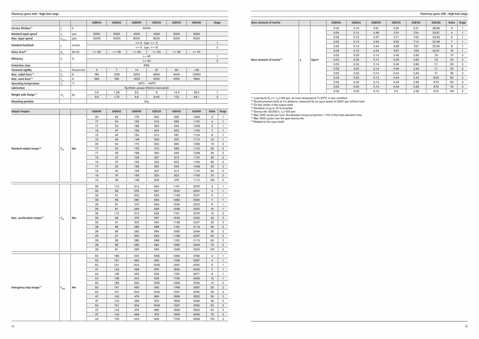
GSB044 GSB062 GSB090 GSB120 GSB142 GSB180 Stage
Service lifetime*1 tL h 30000
Nominal input speed n1 rpm 5000 5000 4000 4000 3000 3000
Max. input speed n1 max. rpm 10000 10000 8000 8000 6000 6000
Standard backlash jt arcmin<= 3 (opt. <= 1) 1<= 5 (opt. <= 3) 2
Noise level*2 Qg dB (A) <= 56 <= 58 <= 60 <= 63 <= 65 <= 67
Efficiency ƞ %>= 97 1>= 94 2
Protection class IP65
Torsional rigidity ct Nm/arcmin 3 7 14 27 60 145
Max. radial force*3 F2r N 780 1530 3250 6800 9400 15600
Max. axial force*3 F2a N 390 765 1625 3700 4700 7800
Operating temperature TB °C -25°C - +90°C
Lubrication Synthetic grease (lifetime-lubricated)
Weight with flange*4 mg kg0.6 1.28 3.6 8 14.3 28.3 10.6 1.73 4.6 9.42 17.2 34.1 2
Mounting position Any
Planetary gears GSB • High-End range
14
Planetary gears GSB • High-End range
15
Output torques GSB044 GSB062 GSB090 GSB120 GSB142 GSB180 Ratio Stage
Nominal output torque*5 T2N Nm
20 62 173 352 656 1266 3 117 54 153 315 583 1122 4 117 50 168 350 649 1248 5 116 47 156 324 602 1163 7 115 45 150 313 581 1124 8 115 45 148 309 576 1112 10 120 62 173 352 656 1266 15 217 54 153 315 583 1122 20 217 50 168 350 649 1248 25 216 47 159 327 612 1174 30 216 47 156 324 602 1163 35 217 50 168 350 649 1248 50 216 47 159 327 612 1174 60 216 47 156 324 602 1163 70 215 45 148 309 576 1112 100 2
Max. acceleration torque*6 T2B Nm
36 112 312 633 1181 2279 3 130 96 276 567 1049 2020 4 130 91 302 629 1168 2247 5 128 85 282 584 1083 2094 7 126 81 270 563 1045 2022 8 126 81 266 556 1038 2002 10 136 112 312 633 1181 2279 15 230 96 276 567 1049 2020 20 230 91 302 629 1168 2247 25 228 85 285 588 1102 2113 30 228 85 282 584 1083 2094 35 230 91 302 629 1168 2247 50 228 85 285 588 1102 2113 60 228 85 282 584 1083 2094 70 226 81 266 556 1038 2002 100 2
Emergency stop torque*7 T2Not Nm
60 186 520 1055 1969 3799 3 150 161 460 945 1748 3367 4 150 151 504 1049 1947 3745 5 147 142 469 973 1805 3490 7 144 135 450 939 1742 3371 8 144 135 444 926 1729 3336 10 160 186 520 1055 1969 3799 15 250 161 460 945 1748 3367 20 250 151 504 1049 1947 3745 25 247 142 476 980 1836 3522 30 247 142 469 973 1805 3490 35 250 151 504 1049 1947 3745 50 247 142 476 980 1836 3522 60 247 142 469 973 1805 3490 70 244 135 444 926 1729 3336 100 2
Mass moment of inertia GSB044 GSB062 GSB090 GSB120 GSB142 GSB180 Ratio Stage
Mass moment of inertia*8 J1 kgcm2
0.03 0.16 0.61 3.25 9.21 28.98 3 10.03 0.14 0.48 2.74 7.54 23.67 4 10.03 0.13 0.47 2.71 7.42 23.29 5 10.03 0.13 0.45 2.62 7.14 22.48 7 10.03 0.13 0.44 2.58 7.07 22.59 8 10.03 0.13 0.44 2.57 7.03 22.51 10 10.03 0.03 0.14 0.46 2.63 7.3 15 20.03 0.03 0.14 0.46 2.63 7.3 20 20.03 0.03 0.14 0.46 2.63 7.1 25 20.03 0.03 0.14 0.46 2.43 7.1 30 20.03 0.03 0.14 0.44 2.43 7.1 35 20.03 0.03 0.14 0.44 2.43 6.92 50 20.03 0.03 0.14 0.43 2.39 6.72 60 20.03 0.03 0.14 0.43 2.39 6.72 70 20.03 0.03 0.14 0.4 2.39 6.72 100 2
*1 Load factor KA=1, n2=100 rpm ,at room temperature T=20°C in new condition*2 Sound pressure level at 1m distance, measured for an input speed of 3000 rpm without load*3 On the center of the output shaft*4 Deviation of up to 10 % possible*5 Service life: 30,000 h, n2=100 rpm*6 Max 1000 cycles per hour. Acceleration torque proportion < 5% of the total operation time*7 Max 1000 cycles over the gear service life*8 Related to the input shaft
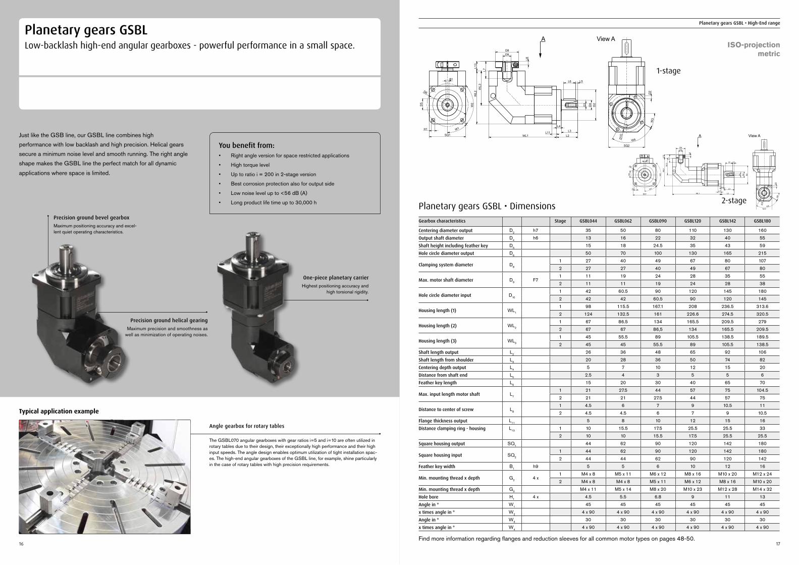
Planetary gears GSBLLow-backlash high-end angular gearboxes - powerful performance in a small space.
Just like the GSB line, our GSBL line combines high performance with low backlash and high precision. Helical gears secure a minimum noise level and smooth running. The right angle shape makes the GSBL line the perfect match for all dynamic applications where space is limited.
You benefit from:• Right angle version for space restricted applications
• High torque level
• Up to ratio i = 200 in 2-stage version
• Best corrosion protection also for output side
• Low noise level up to <56 dB (A)
• Long product life time up to 30,000 h
Angle gearbox for rotary tables
The GSBL070 angular gearboxes with gear ratios i=5 and i=10 are often utilized in rotary tables due to their design, their exceptionally high performance and their high input speeds. The angle design enables optimum utilization of tight installation spac-es. The high-end angular gearboxes of the GSBL line, for example, shine particularly in the case of rotary tables with high precision requirements.
Typical application example
Precision ground bevel gearboxMaximum positioning accuracy and excel-lent quiet operating characteristics.
Precision ground helical gearingMaximum precision and smoothness as
well as minimization of operating noises.
16
Planetary gears GSBL • High-End range
17
Planetary gears GSBL • DimensionsGearbox characteristics Stage GSBL044 GSBL062 GSBL090 GSBL120 GSBL142 GSBL180
Centering diameter output D2 h7 35 50 80 110 130 160
Output shaft diameter D4 h6 13 16 22 32 40 55
Shaft height including feather key D5 15 18 24.5 35 43 59
Hole circle diameter output D6 50 70 100 130 165 215
Clamping system diameter D8
1 27 40 49 67 80 107
2 27 27 40 49 67 80
Max. motor shaft diameter D9 F71 11 19 24 28 35 55
2 11 11 19 24 28 38
Hole circle diameter input D10
1 42 60.5 90 120 145 180
2 42 42 60.5 90 120 145
Housing length (1) WL1
1 98 115.5 167.1 208 236.5 313.6
2 124 132.5 161 226.6 274.5 320.5
Housing length (2) WL2
1 67 86.5 134 165.5 209.5 279
2 67 67 86,5 134 165.5 209.5
Housing length (3) WL3
1 45 55.5 89 105.5 138.5 189.5
2 45 45 55.5 89 105.5 138.5
Shaft length output L2 26 36 48 65 92 106
Shaft length from shoulder L3 20 28 36 50 74 82
Centering depth output L4 5 7 10 12 15 20
Distance from shaft end L5 2.5 4 3 5 5 6
Feather key length L6 15 20 30 40 65 70
Max. input length motor shaft L7
1 21 27.5 44 57 75 104.5
2 21 21 27.5 44 57 75
Distance to center of screw L8
1 4.5 6 7 9 10.5 11
2 4.5 4.5 6 7 9 10.5
Flange thickness output L11 5 8 10 12 15 16
Distance clamping ring - housing L13 1 10 15.5 17.5 25.5 25.5 33
2 10 10 15.5 17.5 25.5 25.5
Square housing output SQ1 44 62 90 120 142 180
Square housing input SQ2
1 44 62 90 120 142 180
2 44 44 62 90 120 142
Feather key width B1 h9 5 5 6 10 12 16
Min. mounting thread x depth G2 4 x1 M4 x 8 M5 x 11 M6 x 12 M8 x 16 M10 x 20 M12 x 24
2 M4 x 8 M4 x 8 M5 x 11 M6 x 12 M8 x 16 M10 x 20
Min. mounting thread x depth G3 M4 x 11 M5 x 14 M8 x 20 M10 x 23 M12 x 28 M14 x 32
Hole bore H1 4 x 4.5 5.5 6.8 9 11 13
Angle in ° W1 45 45 45 45 45 45
x times angle in ° W2 4 x 90 4 x 90 4 x 90 4 x 90 4 x 90 4 x 90
Angle in ° W3 30 30 30 30 30 30
x times angle in ° W4 4 x 90 4 x 90 4 x 90 4 x 90 4 x 90 4 x 90
Find more information regarding flanges and reduction sleeves for all common motor types on pages 48-50.
WL1 L2L3
L4
L11
L6 L5
G3
D4
D2
WL2
L
L13
7
D9D8
L8
WL3
B1
SQ1
H1
D5
D6
W1
W2
W4
W3
SQ2
G2
D10
A View A
D8D9
L
L13
7W
L3W
L2
D2
D4
G3
L5L6
L3
L2
L4
L11
D5
B1
H1
SQ1
D6
W2
W1
L8
WL1
W4
W3
SQ2
D10
G2
A View A
1-stage
2-stage
ISO-projectionmetric
One-piece planetary carrierHighest positioning accuracy and
high torsional rigidity.
18 19
Planetary gears GSBL • High-End range Planetary gears GSBL • High-End range
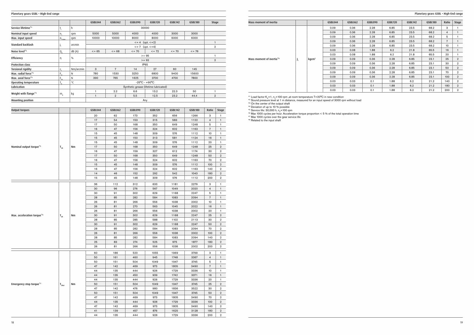
GSBL044 GSBL062 GSBL090 GSBL120 GSBL142 GSBL180 Stage
Service lifetime*1 tL h 30000
Nominal input speed n1 rpm 5000 5000 4000 4000 3000 3000
Max. input speed n1 max. rpm 10000 10000 8000 8000 6000 6000
Standard backlash jt arcmin<= 4 (opt. <=2) 1<= 7 (opt. <=4) 2
Noise level*2 Qg dB (A) <= 65 <= 68 <= 70 <= 72 <= 70 <= 76
Efficiency ƞ %>= 95 1>= 92 2
Protection class IP65
Torsional rigidity ct Nm/arcmin 3 7 14 27 60 145
Max. radial force*3 F2r N 780 1530 3250 6800 9400 15600
Max. axial force*3 F2a N 390 765 1625 3700 4700 7800
Operating temperature TB °C -25°C - +90°C
Lubrication Synthetic grease (lifetime-lubricated)
Weight with flange*4 mg kg1 2.2 6.6 13.2 22.3 50 11 2 5.5 12.5 23.2 44.4 2
Mounting position Any
Output torques GSBL044 GSBL062 GSBL090 GSBL120 GSBL142 GSBL180 Ratio Stage
Nominal output torque*5 T2N Nm
20 62 173 352 656 1266 3 117 54 153 315 583 1122 4 117 50 168 350 649 1248 5 116 47 156 324 602 1163 7 115 45 148 309 576 1112 10 115 45 150 313 581 1124 16 115 45 148 309 576 1112 20 117 50 168 350 649 1248 25 216 47 159 327 612 1174 30 217 50 168 350 649 1248 50 216 47 156 324 602 1163 70 215 45 148 309 576 1112 100 216 47 156 324 602 1163 140 214 46 152 292 542 1043 180 215 45 148 309 576 1112 200 2
Max. acceleration torque*6 T2B Nm
36 112 312 633 1181 2279 3 130 96 276 567 1049 2020 4 130 91 302 629 1168 2247 5 128 85 282 584 1083 2094 7 126 81 266 556 1038 2002 10 126 81 270 563 1045 2022 16 126 81 266 556 1038 2002 20 130 91 302 629 1168 2247 25 228 85 285 588 1102 2113 30 230 91 302 629 1168 2247 50 228 85 282 584 1083 2094 70 226 81 266 556 1038 2002 100 228 85 282 584 1083 2094 140 225 83 274 525 975 1877 180 226 81 266 556 1038 2002 200 2
Emergency stop torque*7 T2Not Nm
60 186 520 1055 1969 3799 3 150 161 460 945 1748 3367 4 150 151 504 1049 1947 3745 5 147 142 469 973 1805 3490 7 144 135 444 926 1729 3336 10 144 135 450 939 1742 3371 16 144 135 444 926 1729 3336 20 150 151 504 1049 1947 3745 25 247 142 476 980 1836 3522 30 250 151 504 1049 1947 3745 50 247 142 469 973 1805 3490 70 244 135 444 926 1729 3336 100 247 142 469 973 1805 3490 140 241 139 457 876 1625 3128 180 244 135 444 926 1729 3336 200 2
Mass moment of inertia GSBL044 GSBL062 GSBL090 GSBL120 GSBL142 GSBL180 Ratio Stage
Mass moment of inertia*8 J1 kgcm2
0.09 0.36 2.28 6.85 23.5 68.2 3 10.09 0.36 2.28 6.85 23.5 68.2 4 10.09 0.36 2.28 6.85 23.5 68.2 5 10.09 0.36 2.28 6.85 23.5 68.2 7 10.09 0.36 2.28 6.85 23.5 68.2 10 10.03 0.08 1.88 6.2 21.8 65.5 16 10.03 0.08 1.88 6.2 21.8 65.5 20 10.09 0.09 0.36 2.28 6.85 23.1 25 20.09 0.09 0.36 2.28 6.85 23.1 30 20.09 0.09 0.36 2.28 6.85 23.1 50 20.09 0.09 0.36 2.28 6.85 23.1 70 20.09 0.09 0.36 2.28 6.85 23.1 100 20.03 0.03 0.1 1.88 6.2 21.2 140 20.03 0.03 0.1 1.88 6.2 21.2 180 20.03 0.03 0.1 1.88 6.2 21.2 200 2
*1 Load factor KA=1, n2=100 rpm ,at room temperature T=20°C in new condition*2 Sound pressure level at 1 m distance, measured for an input speed of 3000 rpm without load*3 On the center of the output shaft*4 Deviation of up to 10 % possible*5 Service life: 30,000 h, n2=100 rpm*6 Max 1000 cycles per hour. Acceleration torque proportion < 5 % of the total operation time*7 Max 1000 cycles over the gear service life*8 Related to the input shaft
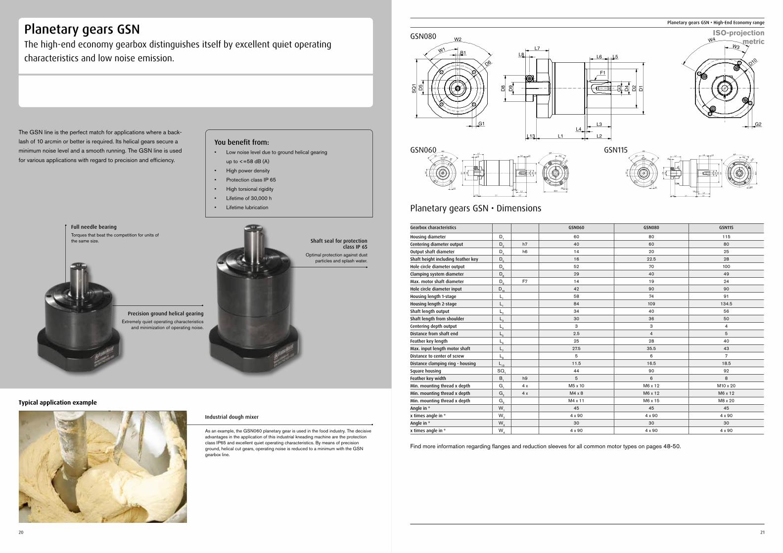
Planetary gears GSNThe high-end economy gearbox distinguishes itself by excellent quiet operating characteristics and low noise emission.
The GSN line is the perfect match for applications where a back-lash of 10 arcmin or better is required. Its helical gears secure a minimum noise level and a smooth running. The GSN line is used for various applications with regard to precision and efficiency.
You benefit from:• Low noise level due to ground helical gearing
up to <=58 dB (A)
• High power density
• Protection class IP 65
• High torsional rigidity
• Lifetime of 30,000 h
• Lifetime lubrication
Industrial dough mixer
As an example, the GSN060 planetary gear is used in the food industry. The decisive advantages in the application of this industrial kneading machine are the protection class IP65 and excellent quiet operating characteristics. By means of precision ground, helical cut gears, operating noise is reduced to a minimum with the GSN gearbox line.
Typical application example
Full needle bearingTorques that beat the competition for units of the same size.
Precision ground helical gearingExtremely quiet operating characteristics
and minimization of operating noise.
20 21
Planetary gears GSN • High-End Economy range
SQ
1
B1
G1
D5
D6
W1
W2
L3L4
L1L13 L2
D1
F1
L6 L5
G3
D4
D2
L7
D8
D9
L8
G2
D10
W3W4
W2
W1B1
G1
D5
D6
D1
D9
D8
L8L7
L1L13 L2
L3L4
D2
D4
G3
L5L6W4
D10
W3
G2SQ1
W2
W1B1
D5
G1
D6
D9
D8
L8L7
L1L13 L2
D2
D1
D4
G3
L5L6 W4W3
D10
G2
SQ1
L4L3
Planetary gears GSN • Dimensions
Gearbox characteristics GSN060 GSN080 GSN115
Housing diameter D1 60 80 115
Centering diameter output D2 h7 40 60 80
Output shaft diameter D4 h6 14 20 25
Shaft height including feather key D5 16 22.5 28
Hole circle diameter output D6 52 70 100
Clamping system diameter D8 29 40 49
Max. motor shaft diameter D9 F7 14 19 24
Hole circle diameter input D10 42 90 90
Housing length 1-stage L1 58 74 91
Housing length 2-stage L1 84 109 134.5
Shaft length output L2 34 40 56
Shaft length from shoulder L3 30 36 50
Centering depth output L4 3 3 4
Distance from shaft end L5 2.5 4 5
Feather key length L6 25 28 40
Max. input length motor shaft L7 27.5 35.5 43
Distance to center of screw L8 5 6 7
Distance clamping ring - housing L13 11.5 16.5 18.5
Square housing SQ1 44 90 92
Feather key width B1 h9 5 6 8
Min. mounting thread x depth G1 4 x M5 x 10 M6 x 12 M10 x 20
Min. mounting thread x depth G2 4 x M4 x 8 M6 x 12 M6 x 12
Min. mounting thread x depth G3 M4 x 11 M6 x 15 M8 x 20
Angle in ° W1 45 45 45
x times angle in ° W2 4 x 90 4 x 90 4 x 90
Angle in ° W3 30 30 30
x times angle in ° W4 4 x 90 4 x 90 4 x 90
Find more information regarding flanges and reduction sleeves for all common motor types on pages 48-50.
GSN080
GSN060 GSN115
ISO-projectionmetric
Shaft seal for protection class IP 65
Optimal protection against dust particles and splash water.
22 23
Planetary gears GSN • High-End Economy range Planetary gears GSN • High-End Economy range
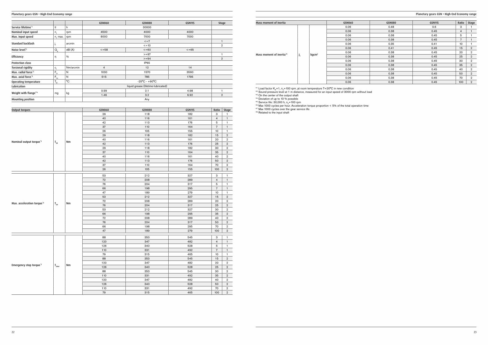
GSN060 GSN080 GSN115 StageService lifetime*1 tl h 30000
Nominal input speed n1 rpm 4500 4000 4000
Max. input speed n1 max. rpm 8000 7000 7000
Standard backlash jt arcmin<=7 1<=10 2
Noise level*2 Qg dB (A) <=58 <=60 <=65
Efficiency ƞ %>=97 1>=94 2
Protection class IP65
Torsional rigidity ct Nm/arcmin 4 12 14
Max. radial force*3 F2r N 1030 1570 3590
Max. axial force*3 F2a N 515 785 1795
Operating temperature TB °C -25°C - +90°C
Lubrication liquid grease (lifetime-lubricated)
Weight with flange*4 mg kg0.99 2.1 4.98 11.46 3.2 6.92 2
Mounting position Any
Output torques GSN060 GSN080 GSN115 Ratio Stage
Nominal output torque*5 T2B Nm
29 118 182 3 140 116 161 4 142 113 176 5 137 110 164 7 126 105 155 10 129 118 182 15 240 116 161 20 242 113 176 25 229 118 182 30 237 110 164 35 240 116 161 40 242 113 176 50 237 110 164 70 226 105 155 100 2
Emergency stop torque*7 T2Not Nm
88 353 545 3 1120 347 482 4 1126 340 528 5 1110 331 492 7 179 315 465 10 188 353 545 15 2
120 347 482 20 2126 340 528 25 288 353 545 30 2110 331 492 35 2120 347 482 40 2126 340 528 50 2110 331 492 70 279 315 465 100 2
Max. acceleration torque*6 T2N Nm
53 212 327 3 172 208 289 4 176 204 317 5 166 198 295 7 147 189 279 10 153 212 327 15 272 208 289 20 276 204 317 25 253 212 327 30 266 198 295 35 272 208 289 40 276 204 317 50 266 198 295 70 247 189 279 100 2
Mass moment of inertia GSN060 GSN080 GSN115 Ratio Stage
Mass moment of inertia*8 J1 kgcm2
0.06 0.48 0.6 3 10.06 0.38 0.45 4 10.06 0.38 0.45 5 10.06 0.38 0.45 7 10.06 0.35 0.41 10 10.06 0.41 0.45 15 20.06 0.38 0.45 20 20.06 0.38 0.45 25 20.06 0.38 0.45 30 20.06 0.38 0.45 35 20.06 0.38 0.45 40 20.06 0.38 0.45 50 20.06 0.38 0.45 70 20.06 0.38 0.45 100 2
*1 Load factor KA=1, n2=100 rpm ,at room temperature T=20°C in new condition*2 Sound pressure level at 1 m distance, measured for an input speed of 3000 rpm without load*3 On the center of the output shaft*4 Deviation of up to 10 % possible*5 Service life: 30,000 h, n2=100 rpm*6 Max 1000 cycles per hour. Acceleration torque proportion < 5% of the total operation time*7 Max 1000 cycles over the gear service life*8 Related to the input shaft
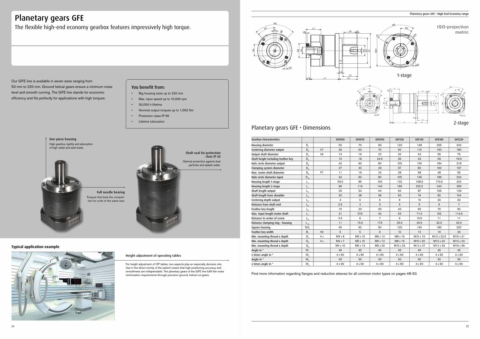
Planetary gears GFEThe flexible high-end economy gearbox features impressively high torque.
Our GFE line is available in seven sizes ranging from 50 mm to 220 mm. Ground helical gears ensure a minimum noise level and smooth running. The GFE line stands for economic efficiency and fits perfectly for applications with high torques.
You benefit from:• Big housing sizes up to 220 mm
• Max. input speed up to 10,000 rpm
• 30,000 h lifetime
• Nominal output torques up to 1,562 Nm
• Protection class IP 65
• Lifetime lubrication
Height adjustment of operating tables
For height adjustment of OP tables, two aspects play an especially decisive role. Use in the direct vicinity of the patient means that high positioning accuracy and smoothness are indispensable. The planetary gears of the GFE line fulfill the noise minimization requirements through precision ground, helical cut gears.
Typical application example
One-piece housingHigh gearbox rigidity and absorption of high radial and axial loads.
Full needle bearingTorques that beat the competi-tion for units of the same size.
24
Planetary gears GFE • High-End Economy range
25
Planetary gears GFE • Dimensions
Gearbox characteristics GFE050 GFE070 GFE090 GFE120 GFE145 GFE180 GFE220
Housing diameter D1 50 70 93 122 148 205 242
Centering diameter output D2 h7 35 50 70 90 110 160 180
Output shaft diameter D4 h6 13 16 22 32 40 55 75
Shaft height including feather key D5 15 18 24.5 35 43 59 79.5
Hole circle diameter output D6 42 60 80 105 130 184 218
Clamping system diameter D8 27 40 49 67 80 100 107
Max. motor shaft diameter D9 F7 11 19 24 28 38 48 55
Hole circle diameter input D10 42 60 80 105 145 186 224
Housing length 1-stage L1 59.5 85 100 132 168.5 173.5 202
Housing length 2-stage L1 86 119 140 186 232.5 243 289
Shaft length output L2 25 34 44 60 87 106 129
Shaft length from shoulder L3 20 28 36 50 74 82 104
Centering depth output L4 4 5 6 8 10 20 20
Distance from shaft end L5 2.5 4 3 5 5 6 7
Feather key length L6 15 20 30 40 65 70 90
Max. input length motor shaft L7 21 27.5 42 53 71.5 102 114.5
Distance to center of screw L8 4.5 6 7 9 10.5 11 11
Distance clamping ring - housing L13 11 15.5 17.5 25.5 25.5 32.5 32.5
Square housing SQ1 45 62 90 120 145 180 220
Feather key width B1 h9 5 5 6 10 12 16 20
Min. mounting thread x depth G1 4 x M4 x 8 M5 x 10 M6 x 12 M8 x 16 M10 x 16 M12 x 22.5 M16 x 31
Min. mounting thread x depth G2 4 x M4 x 7 M5 x 10 M6 x 12 M8 x 16 M10 x 20 M12 x 24 M12 x 24
Min. mounting thread x depth G3 M4 x 10 M5 x 13 M6 x 20 M10 x 23 M12 x 27 M14 x 33 M16 x 36
Angle in ° W1 45 45 45 45 45 45 45
x times angle in ° W2 4 x 90 4 x 90 4 x 90 4 x 90 4 x 90 4 x 90 4 x 90
Angle in ° W3 30 30 30 30 30 30 30
x times angle in ° W4 4 x 90 4 x 90 4 x 90 4 x 90 4 x 90 4 x 90 4 x 90
Find more information regarding flanges and reduction sleeves for all common motor types on pages 48-50.
D5
B1
W2
W1
D6
G1
L8L7
SQ1
D1
D8
L1L13 L2L3
L4
D2
G3
D4
L5L6
W4W3
D10
G2
D9
G1
B1
D5
D6
W2
W1L6 L5
G3
D4
D2
D1
L2
L3
L4
L1L13
L7L8
D9D8
G2
SQ1
D10
W3
W4
1-stage
2-stage
ISO-projectionmetric
Shaft seal for protection class IP 65
Optimal protection against dust particles and splash water.
Planetary gears GFE • High-End Economy range
26
Planetary gears GFE • High-End Economy range
27
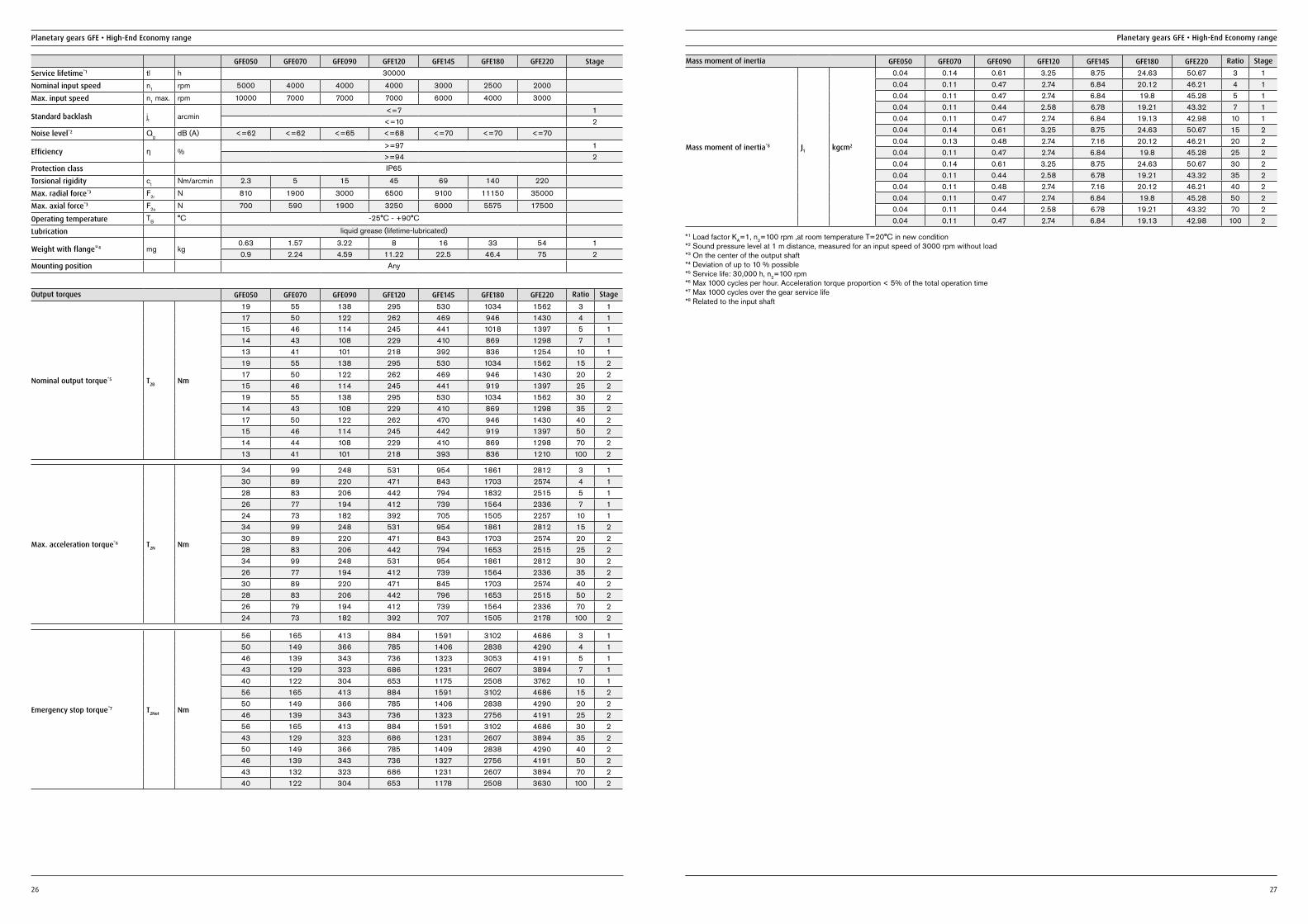
GFE050 GFE070 GFE090 GFE120 GFE145 GFE180 GFE220 StageService lifetime*1 tl h 30000
Nominal input speed n1 rpm 5000 4000 4000 4000 3000 2500 2000
Max. input speed n1 max. rpm 10000 7000 7000 7000 6000 4000 3000
Standard backlash jt arcmin<=7 1<=10 2
Noise level*2 Qg dB (A) <=62 <=62 <=65 <=68 <=70 <=70 <=70
Efficiency ƞ %>=97 1>=94 2
Protection class IP65
Torsional rigidity ct Nm/arcmin 2.3 5 15 45 69 140 220
Max. radial force*3 F2r N 810 1900 3000 6500 9100 11150 35000
Max. axial force*3 F2a N 700 590 1900 3250 6000 5575 17500
Operating temperature TB °C -25°C - +90°C
Lubrication liquid grease (lifetime-lubricated)
Weight with flange*4 mg kg0.63 1.57 3.22 8 16 33 54 10.9 2.24 4.59 11.22 22.5 46.4 75 2
Mounting position Any
Output torques GFE050 GFE070 GFE090 GFE120 GFE145 GFE180 GFE220 Ratio Stage
Nominal output torque*5 T2B Nm
19 55 138 295 530 1034 1562 3 117 50 122 262 469 946 1430 4 115 46 114 245 441 1018 1397 5 114 43 108 229 410 869 1298 7 113 41 101 218 392 836 1254 10 119 55 138 295 530 1034 1562 15 217 50 122 262 469 946 1430 20 215 46 114 245 441 919 1397 25 219 55 138 295 530 1034 1562 30 214 43 108 229 410 869 1298 35 217 50 122 262 470 946 1430 40 215 46 114 245 442 919 1397 50 214 44 108 229 410 869 1298 70 213 41 101 218 393 836 1210 100 2
Emergency stop torque*7 T2Not Nm
56 165 413 884 1591 3102 4686 3 150 149 366 785 1406 2838 4290 4 146 139 343 736 1323 3053 4191 5 143 129 323 686 1231 2607 3894 7 140 122 304 653 1175 2508 3762 10 156 165 413 884 1591 3102 4686 15 250 149 366 785 1406 2838 4290 20 246 139 343 736 1323 2756 4191 25 256 165 413 884 1591 3102 4686 30 243 129 323 686 1231 2607 3894 35 250 149 366 785 1409 2838 4290 40 246 139 343 736 1327 2756 4191 50 243 132 323 686 1231 2607 3894 70 240 122 304 653 1178 2508 3630 100 2
Max. acceleration torque*6 T2N Nm
34 99 248 531 954 1861 2812 3 130 89 220 471 843 1703 2574 4 128 83 206 442 794 1832 2515 5 126 77 194 412 739 1564 2336 7 124 73 182 392 705 1505 2257 10 134 99 248 531 954 1861 2812 15 230 89 220 471 843 1703 2574 20 228 83 206 442 794 1653 2515 25 234 99 248 531 954 1861 2812 30 226 77 194 412 739 1564 2336 35 230 89 220 471 845 1703 2574 40 228 83 206 442 796 1653 2515 50 226 79 194 412 739 1564 2336 70 224 73 182 392 707 1505 2178 100 2
Mass moment of inertia GFE050 GFE070 GFE090 GFE120 GFE145 GFE180 GFE220 Ratio Stage
Mass moment of inertia*8 J1 kgcm2
0.04 0.14 0.61 3.25 8.75 24.63 50.67 3 10.04 0.11 0.47 2.74 6.84 20.12 46.21 4 10.04 0.11 0.47 2.74 6.84 19.8 45.28 5 10.04 0.11 0.44 2.58 6.78 19.21 43.32 7 10.04 0.11 0.47 2.74 6.84 19.13 42.98 10 10.04 0.14 0.61 3.25 8.75 24.63 50.67 15 20.04 0.13 0.48 2.74 7.16 20.12 46.21 20 20.04 0.11 0.47 2.74 6.84 19.8 45.28 25 20.04 0.14 0.61 3.25 8.75 24.63 50.67 30 20.04 0.11 0.44 2.58 6.78 19.21 43.32 35 20.04 0.11 0.48 2.74 7.16 20.12 46.21 40 20.04 0.11 0.47 2.74 6.84 19.8 45.28 50 20.04 0.11 0.44 2.58 6.78 19.21 43.32 70 20.04 0.11 0.47 2.74 6.84 19.13 42.98 100 2
*1 Load factor KA=1, n2=100 rpm ,at room temperature T=20°C in new condition*2 Sound pressure level at 1 m distance, measured for an input speed of 3000 rpm without load*3 On the center of the output shaft*4 Deviation of up to 10 % possible*5 Service life: 30,000 h, n2=100 rpm*6 Max 1000 cycles per hour. Acceleration torque proportion < 5% of the total operation time*7 Max 1000 cycles over the gear service life*8 Related to the input shaft
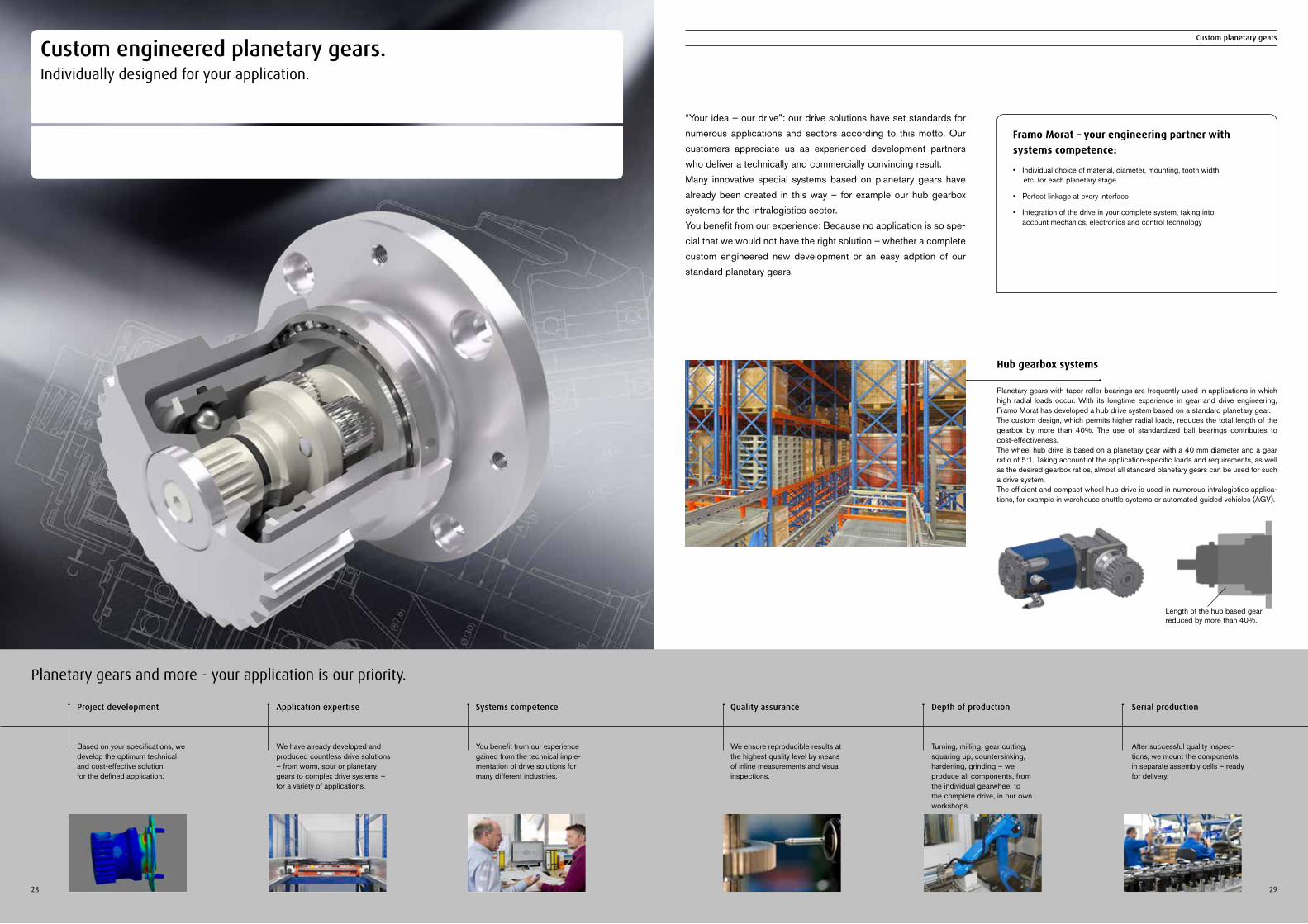
Project development
Based on your specifications, we develop the optimum technical and cost-effective solution for the defined application.
Application expertise
We have already developed and produced countless drive solutions – from worm, spur or planetary gears to complex drive systems – for a variety of applications.
Systems competence
You benefit from our experience gained from the technical imple-mentation of drive solutions for many different industries.
Planetary gears and more – your application is our priority.
Framo Morat – your engineering partner with systems competence:
• Individual choice of material, diameter, mounting, tooth width, etc. for each planetary stage
• Perfect linkage at every interface
• Integration of the drive in your complete system, taking into account mechanics, electronics and control technology
Custom planetary gears
Quality assurance
We ensure reproducible results at the highest quality level by means of inline measurements and visual inspections.
Depth of production
Turning, milling, gear cutting, squa ring up, countersinking, hardening, grinding – we pro duce all components, from the individual gearwheel to the complete drive, in our own workshops.
Serial production
After successful quality inspec-tions, we mount the components in separate assembly cells – ready for delivery.
28 29
Custom engineered planetary gears.Individually designed for your application.
“Your idea – our drive”: our drive solutions have set standards for numerous applications and sectors according to this motto. Our customers appreciate us as experienced development partners who deliver a technically and commercially convincing result. Many innovative special systems based on planetary gears have already been created in this way – for example our hub gearbox systems for the intralogistics sector. You benefit from our experience: Because no application is so spe-cial that we would not have the right solution – whether a complete custom engineered new development or an easy adption of our standard planetary gears.
Hub gearbox systems
Planetary gears with taper roller bearings are frequently used in applications in which high radial loads occur. With its longtime experience in gear and drive engineering, Framo Morat has developed a hub drive system based on a standard planetary gear. The custom design, which permits higher radial loads, reduces the total length of the gearbox by more than 40%. The use of standardized ball bearings contributes to cost-effectiveness.The wheel hub drive is based on a planetary gear with a 40 mm diameter and a gear ratio of 5:1. Taking account of the application-specific loads and requirements, as well as the desired gearbox ratios, almost all standard planetary gears can be used for such a drive system.The efficient and compact wheel hub drive is used in numerous intralogistics applica-tions, for example in warehouse shuttle systems or automated guided vehicles (AGV).
Length of the hub based gear reduced by more than 40%.
30 31
Custom planetary gears
30 31
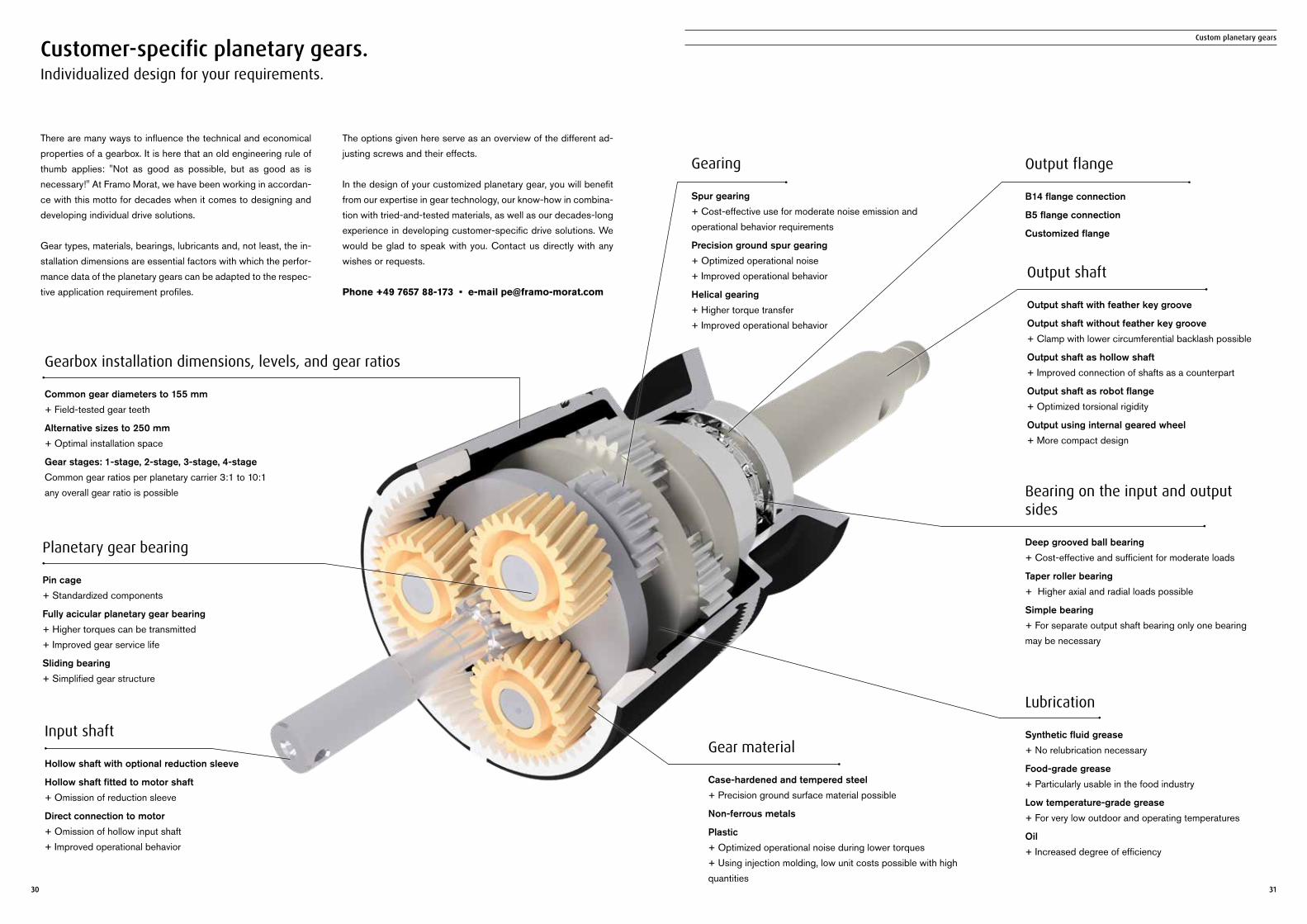
Customer-specific planetary gears.Individualized design for your requirements.
Gearbox installation dimensions, levels, and gear ratios
Common gear diameters to 155 mm + Field-tested gear teeth
Alternative sizes to 250 mm + Optimal installation space
Gear stages: 1-stage, 2-stage, 3-stage, 4-stage Common gear ratios per planetary carrier 3:1 to 10:1 any overall gear ratio is possible
Input shaft
Hollow shaft with optional reduction sleeve
Hollow shaft fitted to motor shaft + Omission of reduction sleeve
Direct connection to motor + Omission of hollow input shaft + Improved operational behavior
Output flange
B14 flange connection
B5 flange connection
Customized flange
Gearing
Spur gearing + Cost-effective use for moderate noise emission and operational behavior requirements
Precision ground spur gearing + Optimized operational noise + Improved operational behavior
Helical gearing + Higher torque transfer+ Improved operational behavior
Lubrication
Synthetic fluid grease + No relubrication necessary
Food-grade grease + Particularly usable in the food industry
Low temperature-grade grease + For very low outdoor and operating temperatures
Oil + Increased degree of efficiency
Bearing on the input and output sides
Deep grooved ball bearing + Cost-effective and sufficient for moderate loads
Taper roller bearing + Higher axial and radial loads possible
Simple bearing + For separate output shaft bearing only one bearing may be necessary
Planetary gear bearing
Pin cage + Standardized components
Fully acicular planetary gear bearing + Higher torques can be transmitted + Improved gear service life
Sliding bearing + Simplified gear structure
Output shaft
Output shaft with feather key groove
Output shaft without feather key groove + Clamp with lower circumferential backlash possible
Output shaft as hollow shaft + Improved connection of shafts as a counterpart
Output shaft as robot flange + Optimized torsional rigidity
Output using internal geared wheel + More compact design
Gear material
Case-hardened and tempered steel + Precision ground surface material possible
Non-ferrous metals
Plastic + Optimized operational noise during lower torques + Using injection molding, low unit costs possible with high quantities
There are many ways to influence the technical and economical properties of a gearbox. It is here that an old engineering rule of thumb applies: "Not as good as possible, but as good as is necessary!" At Framo Morat, we have been working in accordan-ce with this motto for decades when it comes to designing and developing individual drive solutions.
Gear types, materials, bearings, lubricants and, not least, the in-stallation dimensions are essential factors with which the perfor-mance data of the planetary gears can be adapted to the respec-tive application requirement profiles.
The options given here serve as an overview of the different ad-justing screws and their effects.
In the design of your customized planetary gear, you will benefit from our expertise in gear technology, our know-how in combina-tion with tried-and-tested materials, as well as our decades-long experience in developing customer-specific drive solutions. We would be glad to speak with you. Contact us directly with any wishes or requests.
Phone +49 7657 88-173 • e-mail [email protected]
32 33
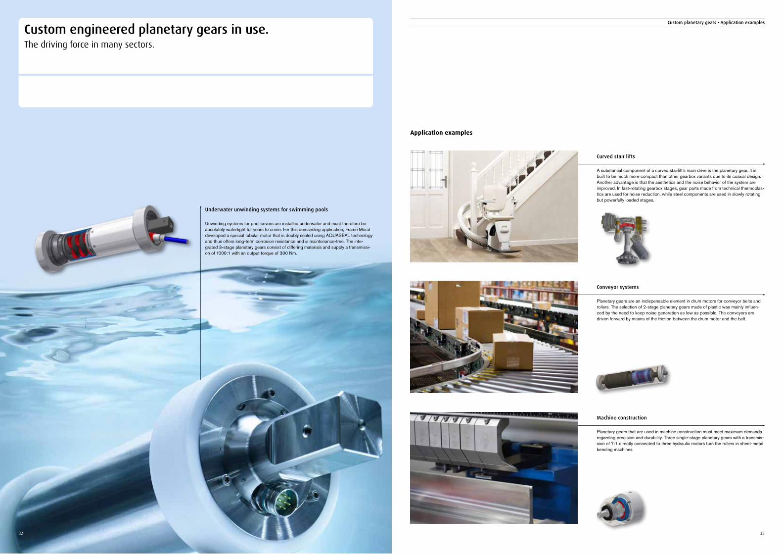
Underwater unwinding systems for swimming pools
Unwinding systems for pool covers are installed underwater and must therefore be absolutely watertight for years to come. For this demanding application, Framo Morat developed a special tubular motor that is doubly sealed using AQUASEAL technology and thus offers long-term corrosion resistance and is maintenance-free. The inte-grated 3-stage planetary gears consist of differing materials and supply a transmissi-on of 1000:1 with an output torque of 300 Nm.
Curved stair lifts
A substantial component of a curved stairlift’s main drive is the planetary gear. It is built to be much more compact than other gearbox variants due to its coaxial design. Another advantage is that the aesthetics and the noise behavior of the system are improved. In fast-rotating gearbox stages, gear parts made from technical thermoplas-tics are used for noise reduction, while steel components are used in slowly rotating but powerfully loaded stages.
Machine construction
Planetary gears that are used in machine construction must meet maximum demands regarding precision and durability. Three single-stage planetary gears with a transmis-sion of 7:1 directly connected to three hydraulic motors turn the rollers in sheet-metal bending machines.
Application examples
Conveyor systems
Planetary gears are an indispensable element in drum motors for conveyor belts and rollers. The selection of 2-stage planetary gears made of plastic was mainly influen-ced by the need to keep noise generation as low as possible. The conveyors are driven forward by means of the friction between the drum motor and the belt.
Custom planetary gears • Application examples
Custom engineered planetary gears in use.The driving force in many sectors.
34 35
Custom planetary gears • Application examples Custom planetary gears • Application examples
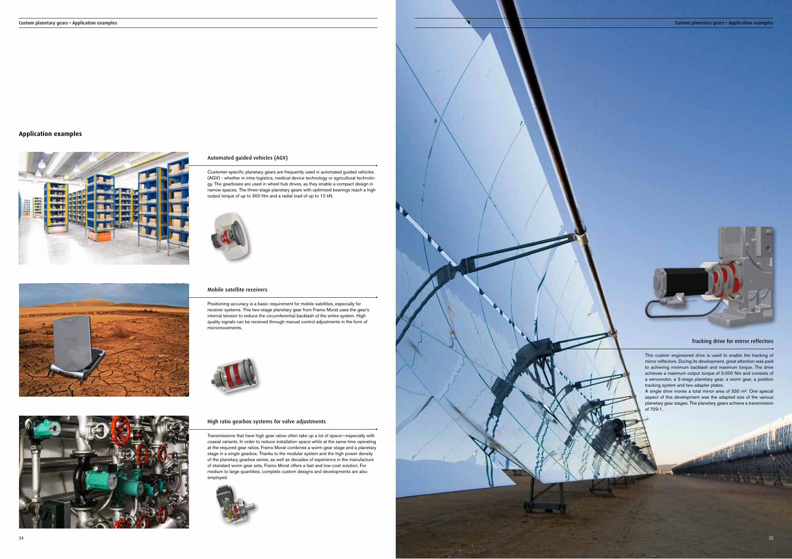
Automated guided vehicles (AGV)
Customer-specific planetary gears are frequently used in automated guided vehicles (AGV) - whether in intra-logistics, medical device technology or agricultural technolo-gy. The gearboxes are used in wheel hub drives, as they enable a compact design in narrow spaces. The three-stage planetary gears with optimized bearings reach a high output torque of up to 300 Nm and a radial load of up to 12 kN.
High ratio gearbox systems for valve adjustments
Transmissions that have high gear ratios often take up a lot of space—especially with coaxial variants. In order to reduce installation space while at the same time operating at the required gear ratios, Framo Morat combines a worm gear stage and a planetary stage in a single gearbox. Thanks to the modular system and the high power density of the planetary gearbox series, as well as decades of experience in the manufacture of standard worm gear sets, Framo Morat offers a fast and low-cost solution. For medium to large quantities, complete custom designs and developments are also employed.
Application examples
Mobile satellite receivers
Positioning accuracy is a basic requirement for mobile satellites, especially for receiver systems. This two-stage planetary gear from Framo Morat uses the gear's internal tension to reduce the circumferential backlash of the entire system. High quality signals can be received through manual control adjustments in the form of micromovements.
Tracking drive for mirror reflectors
This custom engineered drive is used to enable the tracking of mirror reflectors. During its development, great attention was paid to achieving minimum backlash and maximum torque. The drive achieves a maximum output torque of 5.000 Nm and consists of a servomotor, a 3-stage planetary gear, a worm gear, a position tracking system and two adapter plates. A single drive moves a total mirror area of 330 m². One special aspect of this development was the adapted size of the various planetary gear stages. The planetary gears achieve a transmission of 729:1.
36 37
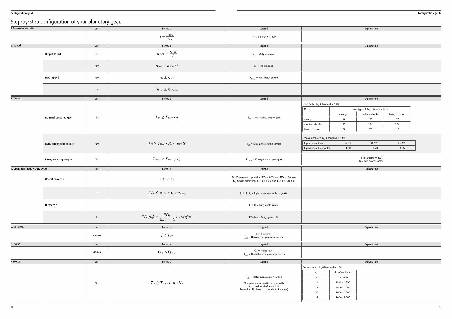
1. Transmission ratio Unit Formula Legend Explanation
i = n 2(A)
n1(A)i = transmission ratio
5. Backlash Unit Formula Legend Explanation
arcmin j t # j t(A)jt = Backlash
jt(A) = Backlash of your application
2. Speed Unit Formula Legend Explanation
Output speed rpm n 2(A) =i
n1(A)n2 = Output speed
rpm n1(A) = n 2(A) : i n1 = Input speed
Input speed rpm n1 $ n1(A) n1 max. = max. Input speed
rpm n1max. $ n1(A)max.
4. Operation mode / Duty cycle Unit Formula Legend Explanation
Operation mode S1 or S5 S1: Continuous operation: ED > 60% and ED > 20 min S5: Cyclic operation: ED <= 60% and ED <= 20 min
min ED(t) = ta + tc + td(min.) tb, tc, td, te = Cyle times see table page 47
Duty cycle ED (t) = Duty cycle in min
% ED(%) =ED(t) + te
ED(t) : 100(%) ED (%) = Duty cycle in %
3. Torque Unit Formula Legend Explanation
Nominal output torque Nm T2N $ T2N(A) : h T2N = Nominal output torque
Load factor KA (Standard = 1.0)
Drive Load type of the driven machine
steady medium shocks heavy shocks
steady 1.0 1.25 1.75
medium shocks 1.25 1.5 2.0
heavy shocks 1.5 1.75 2.25
Max. acceleration torque Nm T2B $ T2B(A) : K a : b B : S T2B = Max. acceleration torque
Operational ratio bB (Standard = 1.0)
Operational time 4-8 h 8-12 h >=12h
Operational time factor 1.00 1.20 1.35
Emergency stop torque Nm T2NOT $ T2max.(A) : h T2 NOT = Emergency stop torque S (Standard = 1.0) ƞ = see power tables
Step-by-step configuration of your planetary gear.
Configuration guide Configuration guide
6. Noise Unit Formula Legend Explanation
dB (A) Q g #Q g(A)Qg = Noise level
Qg(A) = Noise level of your application
7. Motor Unit Formula Legend Explanation
Nm T2B $ T mB : i : h : K S
TmB = Motor-acceleration torque
Compare motor shaft diameter with input hollow shaft diameter
Exception: PL line (< motor shaft diameter)
Service factor KS (Standard = 1.0)
KS No. of cycles / h
1.0 0 - 1000
1.1 1000 - 1500
1.3 1500 - 2000
1.6 2000 - 3000
1.8 3000 - 5000
Configuration guide Configuration guide
38 39
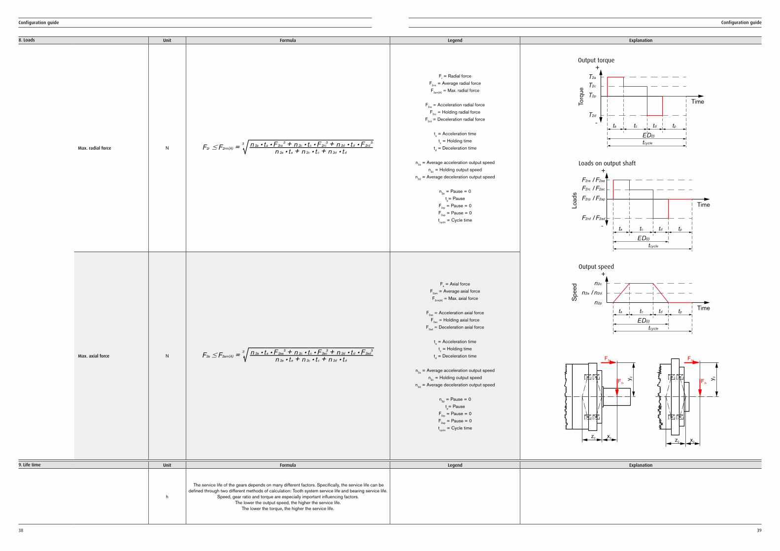
8. Loads Unit Formula Legend Explanation
Max. radial force N F2r # F2rm(A) =n 2a : ta + n 2c : tc + n 2d : td
n 2a : ta : F 2ra3 + n 2c : tc : F 2rc
3 + n 2d : td : F 2rd33
Fr = Radial force F2rm = Average radial force F2am(A) = Max. radial force
F2ra = Acceleration radial force
F2rc = Holding radial forceF2rd = Deceleration radial force
ta = Acceleration time
tc = Holding timetd = Deceleration time
n2a = Average acceleration output speed
n2c = Holding output speedn2d = Average deceleration output speed
n2p = Pause = 0
tp= PauseF2rp = Pause = 0F2ap = Pause = 0tcycle = Cycle time
T2a
+
-
T2c
T2p
T2d
ta tc
tcycle
td tp
Time
Output torque
Torq
ue
ED(t)
F2ra / F2aa
+
-
F2rc / F2ac
F2rp / F2ap
F2rd / F2ad
ta tc
tcycle
td tp
Time
Loads on output shaft
Load
s
ED(t)
+n2c
n2p
n2a / n2d
ta tc
tcycle
td tpTime
Output speed
Spe
ed
ED(t)
F2a
F2r
z2 x2
y2
F2a
F2r
z2 x2
y2
Max. axial force N F2a # F2am(A) =n 2a : ta + n 2c : tc + n 2d : td
n 2a : ta : F 2aa3 + n 2c : tc : F 2ac
3 + n 2d : td : F 2ad33
Fa = Axial force F2am = Average axial force F2rm(A) = Max. axial force
F2aa = Acceleration axial force
F2ac = Holding axial forceF2ad = Deceleration axial force
ta = Acceleration time
tc = Holding timetd = Deceleration time
n2a = Average acceleration output speed
n2c = Holding output speedn2d = Average deceleration output speed
n2p = Pause = 0
tp= PauseF2rp = Pause = 0F2ap = Pause = 0tcycle = Cycle time
9. Life time Unit Formula Legend Explanation
h
The service life of the gears depends on many different factors. Specifically, the service life can be defined through two different methods of calculation: Tooth system service life and bearing service life.
Speed, gear ratio and torque are especially important influencing factors. The lower the output speed, the higher the service life.
The lower the torque, the higher the service life.
40 41
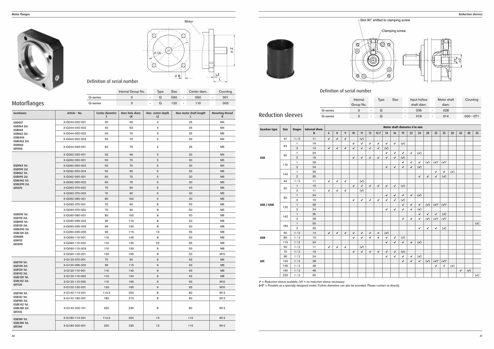
Motor flanges Reduction sleeves
Gearboxes Article - No. Center diameter Z
Bore hole diam. LK
Max. center depth LZ
Max motor shaft length L
Mounting thread B
GSD047 GSD064 2st. GSB044 GSB062 2st. GSBL044 GSBL062 2st. GSN060 GFE050
3-G044-030-001 30 46 4 25 M4
3-G044-040-002 40 63 4 25 M4
3-G044-050-002 50 70 3 25 M5
3-G044-050-004 50 70 3 30 M4
3-G044-060-001 60 75 4 25 M5
GSD064 1st. GSD090 2st. GSB062 1st. GSB090 2st. GSBL062 1st. GSBL090 2st. GFE070
3-G062-030-001 30 46 5 30 M4
3-G062-050-001 50 70 5 30 M5
3-G062-050-002 50 70 5 30 M4
3-G062-050-004 50 95 5 30 M6
3-G062-060-001 60 75 5 30 M6
3-G062-060-002 60 75 5 30 M5
3-G062-070-002 70 90 5 40 M6
3-G062-070-003 70 90 5 30 M5
3-G062-080-001 80 100 5 30 M6
GSD090 1st. GSD110 2st. GSB090 1st. GSB120 2st. GSBL090 1st. GSBL120 2st. GSN080 GSN115 GFE090
3-G090-070-001 70 90 8 50 M6
3-G090-070-002 70 90 8 50 M5
3-G090-080-001 80 100 8 50 M6
3-G090-095-002 95 115 8 50 M8
3-G090-095-003 95 130 8 50 M8
3-G090-095-006 95 115 13 55 M8
3-G090-110-001 110 145 8 50 M8
3-G090-110-002 110 145 22 65 M8
3-G090-110-003 110 130 8 50 M8
3-G090-130-001 130 165 8 50 M10
GSD110 1st. GSD140 2st. GSB120 1st. GSB142 2st. GSBL120 1st. GSBL142 2st. GFE120
3-G120-070-001 70 90 9 63 M6
3-G120-095-002 95 115 9 63 M8
3-G120-110-001 110 145 9 63 M8
3-G120-110-003 110 130 9 63 M8
3-G120-110-005 110 165 9 63 M10
3-G120-130-001 130 165 9 63 M10
GSD140 1st. GSB142 1st. GSB180 2st. GSBL142 1st. GSBL180 2st. GFE145
3-G142-114-001 114.3 200 8 80 M12
3-G142-180-001 180 215 8 80 M12
3-G142-200-101 200 235 8 80 M12
GSB180 1st. GSBL180 1st. GFE180
3-G180-114-001 114.3 200 13 115 M12
3-G180-200-001 200 235 13 115 M12
Definition of serial number
Internal Group No. Type Size Center diam. Counting
G-series 3 - G 090 - 090 - 001
G-series 3 - G 120 - 110 003 Motorflanges
Motor
Reduction sleeves
Gearbox type Size Stages Internal diam. D
Motor shaft diameter d in mm
6 8 9 10 11 12 12.7 14 16 19 22 24 28 32 35 38 42 48 55
GSD
47 1 / 2 11 ✓ ✓ ✓ (✓)
641 19 ✓ ✓ ✓ ✓ ✓ ✓ (✓)2 14 ✓ ✓ ✓ ✓ ✓ ✓ ✓ (✓)
901 24 ✓ ✓ ✓ ✓ (✓)2 19 ✓ ✓ ✓ ✓ ✓ ✓ (✓)
1101 28 ✓ ✓ ✓ (✓) (✓)* (✓)*2 24 ✓ ✓ ✓ ✓ (✓)
1401 38 ✓ ✓ (✓)2 35 ✓ ✓ ✓ (✓)
GSB / GSBL
44 1 / 2 11 ✓ ✓ ✓ (✓)
621 19 ✓ ✓ ✓ ✓ ✓ ✓ (✓)2 11 ✓ ✓ ✓ (✓)
901 24 ✓ ✓ ✓ ✓ (✓)2 19 ✓ ✓ ✓ ✓ ✓ ✓ (✓)
1201 28 ✓ ✓ ✓ (✓) (✓)* (✓)*2 24 ✓ ✓ ✓ ✓ (✓)
1421 35 ✓ ✓ ✓ (✓)2 28 ✓ ✓ ✓ (✓) (✓)* (✓)*
1801 55 (✓)2 35 ✓ ✓ ✓ (✓)
GSN
60 1 / 2 14 ✓ ✓ ✓ ✓ ✓ ✓ ✓ (✓)80 1 / 2 19 ✓ ✓ ✓ ✓ ✓ ✓ (✓)
115 1 / 2 24 ✓ ✓ ✓ ✓ (✓)
GFE
50 1 / 2 11 ✓ ✓ ✓ (✓)70 1 / 2 19 ✓ ✓ ✓ ✓ ✓ ✓ (✓)90 1 / 2 24 ✓ ✓ ✓ ✓ (✓)
120 1 / 2 28 ✓ ✓ ✓ (✓) (✓)* (✓)*145 1 / 2 38 ✓ ✓ (✓)180 1 / 2 48 ✓ (✓)220 1 / 2 55 (✓)
✓ = Reduction sleeve available; (✓) = no reduction sleeve necessary;(✓)* = Possible as a specially designed model. Further diameters can also be provided. Please contact us directly.
d
Definition of serial number
Internal Group No.
Type Size Input hollow shaft diam.
Motor shaft diam.
Counting
G-series 3 - G - 035 - 028
G-series 3 - G - 019 - 014 000 - 071
Slot 90° shifted to clamping screw
Clamping screw
42 43
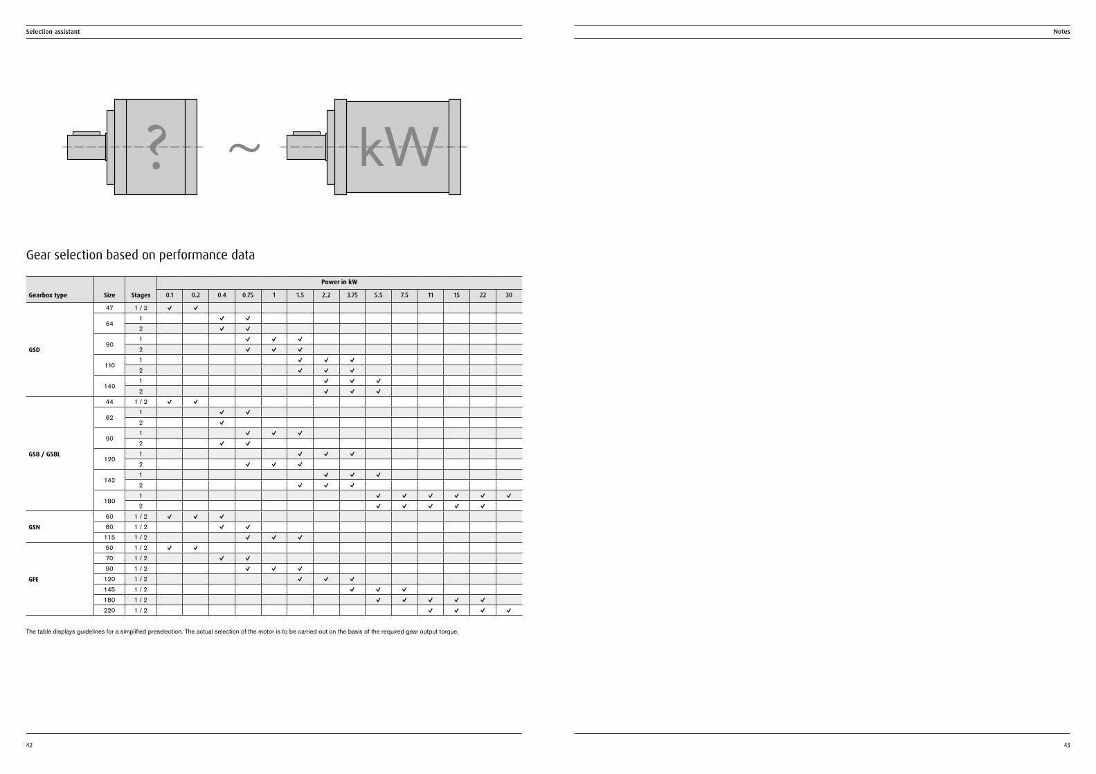
Gear selection based on performance data
Gearbox type Size Stages
Power in kW
0.1 0.2 0.4 0.75 1 1.5 2.2 3.75 5.5 7.5 11 15 22 30
GSD
47 1 / 2 ✓ ✓
641 ✓ ✓2 ✓ ✓
901 ✓ ✓ ✓2 ✓ ✓ ✓
1101 ✓ ✓ ✓2 ✓ ✓ ✓
1401 ✓ ✓ ✓2 ✓ ✓ ✓
GSB / GSBL
44 1 / 2 ✓ ✓
621 ✓ ✓2 ✓
901 ✓ ✓ ✓2 ✓ ✓
1201 ✓ ✓ ✓2 ✓ ✓ ✓
1421 ✓ ✓ ✓2 ✓ ✓ ✓
1801 ✓ ✓ ✓ ✓ ✓ ✓2 ✓ ✓ ✓ ✓ ✓
GSN
60 1 / 2 ✓ ✓ ✓80 1 / 2 ✓ ✓
115 1 / 2 ✓ ✓ ✓
GFE
50 1 / 2 ✓ ✓70 1 / 2 ✓ ✓90 1 / 2 ✓ ✓ ✓
120 1 / 2 ✓ ✓ ✓145 1 / 2 ✓ ✓ ✓180 1 / 2 ✓ ✓ ✓ ✓ ✓220 1 / 2 ✓ ✓ ✓ ✓
The table displays guidelines for a simplified preselection. The actual selection of the motor is to be carried out on the basis of the required gear output torque.
Selection assistant Notes
~? kW
With 100+ years of experience in the areas of gearwheel technology, worm gear sets and drive systems, Framo Morat supplies a comprehensive range of products that cover a wide spectrum of applications. In addition to our complete rangeof standard products, we also design and implement custom engineered drive solutions.
Framo Morat is your reliable partner for worm, spur or planetary gears; complete gearmotors; and complex drive systems – and for your drive concept too!
Your idea – Our drive.For us, everything revolves around you.
Gear technology
Gearwheels with internal or external tooth systems, rotor shafts, pinions and chain pulleys according to individual customer requirements.
Worm gear sets
Framo Morat is a leading international supplier – manufacturing over 1 million gear sets a year, a major proportion of which are produced to customer specifications.
Plastic injection molding technology
In the field of precision injection molding technology, we produce gear parts, plastic/metal connections or technical parts for individual tasks.
Framo Morat GmbH & Co. KGFranz-Morat-Str. 679871 EisenbachGermanyPhone +49 7657 88-0Fax +49 7657 88-333E-Mail [email protected]
Drive technology
Our innovative standard drives such as planetary gears, linear or rotary actuators, as well as complete custom engineered drive solutions, are in use in numerous applications.
PLG-EN-2018-03-01