Embed Size (px)
Citation preview

Augusta Public Works Plan Preparation Guidelines& Engineering Department January 2001
PLAN PRESENTATION GUIDE
TABLE OF CONTENTS
INTRODUCTION
• Chapter 1 . . . . . . . . . .Sequence of Plans Preparation • Chapter 2 . . . . . . . . . .Project Plan Information • Chapter 3 . . . . . . . . . .Typical Sections • Chapter 4 . . . . . . . . . .Quantities and Estimates • Chapter 5 . . . . . . . . . .Roadway Plans • Chapter 6 . . . . . . . . . .Drainage • Chapter 7 . . . . . . . . . .Erosion and Sediment Control Plans • Chapter 8 . . . . . . . . . .Roadway Profiles • Chapter 9 . . . . . . . . . .Roadway Cross Sections • Chapter 10 . . . . . . . . .Intersections and Interchanges • Chapter 11 . . . . . . . . .Utilities • Chapter 12 . . . . . . . . .Maintenance of Traffic, Sequence of Operations, and Staging • Chapter 13 . . . . . . . . .Signing and Pavement Marking • Chapter 14 . . . . . . . . .Signalization • Chapter 15 . . . . . . . . .Highway Lighting • Chapter 16 . . . . . . . . .Landscaping • Chapter 17 . . . . . . . . .Bridges and Structures • Chapter 18 . . . . . . . . ."Georgia Standard Drawings" and Special Details • Chapter 19 . . . . . . . . .Special Provisions • Chapter 20 . . . . . . . . .Right-of-Way Plans • Chapter 21 . . . . . . . . .Documentations of Design and Quantities • Chapter 22 . . . . . . . . .Checklists

Augusta Public Works Plan Preparation Guidelines& Engineering Department January 2001
CHAPTER 1SEQUENCE OF PLANS PREPARATION
I. GENERALThe construction plans and the specifications are the key documents on which the contractorbases his bid for a construction project. These documents are used in the construction of theproject. Hence, it is imperative that the construction plans and specifications set forth thework to be done in a logical, concise, and consistent manner to avoid misinterpretation.The construction plans should be prepared and coordinated to complement the Department'sPlan Development Process, which provides a sequence of events, while systematicallyundergoing various stages of review and revision to ensure technically correct and clearplans.
II. REQUIRED INFORMATION FOR CONSTRUCTION DESIGN PLANSA. Preliminary Roadway Plans
Conceptual Layout - Initial design begins with a conceptual alignment. In mostcases an initial concept layout will be provided by the Department. Any alternateconcept layouts prepared shall ensure a buildable, cost effective project. Theseconcept alternatives shall be submitted to the Department for approval. Afterapproval has been issued, a Concept Report shall be prepared.
Database Preparation - After a conceptual alignment has been approved, databasepreparation should begin. The plan preparer will furnish mapping. Required surveyswill then be performed and additional information within the project limits will begathered to develop accurate and up-to-date base mapping. These required surveysshall include detailed right-of-way and property surveys, drainage surveys, andadditional location surveys as needed (see the "Scope and Procedure" andappendices in the Consultant Services Agreement).
Plan Sheet Preparation - Prepare preliminary plans using the approved concept planalong with the completed database. Upon 30%completion of preliminary plans,submit plans to the Department for review. Incorporate review comments into thePreliminary Plans and resubmit for 60% review.
B. Right-of-Way Plans
Plan Sheet Preparation - Prepare right-of-way plans based on the developedpreliminary plans and according to the requirements for preparation of right-of-wayplans as found in the Consultant Services Agreement. Preliminary right-of-wayplans shall be submitted with the 60% complete submittal of the construction plans.Upon completion of right-of-way plans, submit plans along with 90% complete

Augusta Public Works Plan Preparation Guidelines& Engineering Department January 2001
construction plans to the Department for review and approval. Incorporatecorrections into the right-of-way plans and resubmit for approval.
C. Final Roadway Plans
Plan Sheet Preparation - Base final plans on the developed preliminary plans, andaccording to the requirements for preparation of construction plans per theDepartment's guidelines. Upon 90% completion of final plans and specifications,submit the plans to the Department for a Final Field Plan Review (FFPR). A FinalField Plan Review (FFPR) will then be scheduled by the Department where theplans will be reviewed for completeness and uniformity of presentation per theguidelines set forth in the Plan Presentation Guide. After all review comments fromthe FFPR have been incorporated into the final plans, the Department shall declarethe construction plans adequate for submission as final plans.
III. SHEET LAYOUT1. When the plans are completed, assemble the sheets in the following
sequence (This plan assembly is to be used as a general guide and may bechanged to better fit and, or to include any sheets not listed herein):CoverIndexRevision Summary Typical SectionsSummary of Quantities (Roadway and Signing & Marking)Detailed EstimateConstruction Layout SheetPlan and Profile Sheets (mainline/profile can be on same or separate sheet)Plan and Profile Sheets (crossroads, side roads, local service roads anddetours)Interchange Plan SheetsProfile of Ramps or SidestreetsDriveway Profiles (as required)Retaining Wall EnvelopesDrainage MapDrainage ProfilesStaging and Detour Plans (with cross sections, if needed)Special Grading SheetsWetland Mitigation SheetsUtility PlansSigning & Marking Plans and DetailsTraffic Signal Plans and DetailsLighting Plans and DetailsSound Barrier Plans and DetailsErosion and Sediment Control PlansEarthwork Cross Sections

Augusta Public Works Plan Preparation Guidelines& Engineering Department January 2001
Borrow Pit Location and NotesConstruction Details
Special Design CulvertsGeorgia StandardsRetaining Wall Plans and DetailsBridge Plans and Details
2. After the sheets have been assembled in order, number each sheetconsecutively beginning with the cover sheet as No. 1 and continuingthrough the plan set. Make an index listing all sheets by number anddescription thus far. At this point make a thorough check of the plans listingall of the construction details, special design culverts, and Georgia StandardDrawings numerically. The index may now be completed and the latestrevision dates shown for construction details, special design culverts, andGeorgia Standards.
3. The total number of sheets in the plans should be shown immediately belowthe index. This number will not necessarily be the same number as the lastsheet in the plans and may be shown in pencil since it is subject to changeeach time sheets are added to or omitted from the plans.
4. If a sheet is added after the final sheets are numbered and the final plansapproved, place the sheet in the appropriate location and assign it an alphadesignation.
5. If a revision is made after the final plans have been let to contract, then markthe original sheet "VOID" and insert a new sheet with the applicable revisionand an alpha character included in the sheet listing. Make any subsequentrevisions to the new sheet included in the plans. The voided sheet remains inthe plans.

Augusta Public Works Plan Preparation Guidelines& Engineering Department January 2001
CHAPTER 2PROJECT PLAN INFORMATION
I. GENERALProject plan information should be included in the construction plans utilizing a generalnote sheet. This sheet would include construction notes that are project specific and are notcovered under the current Standard Specifications and Supplemental and/or Special Details.Notes that are needed in the construction contract may be included in the General Notes ifspecial attention is necessary to eliminate a possible source of errors or conflict, or toexpedite the work.
II. COVER SHEETA cover sheet is required for each set of construction plans. The cover sheet is extremelyimportant for contract purposes and for project identification. The cover sheet shouldinclude but is not limited to information pertaining to the project name, project number,project identification number, county, congressional district, and a standard note that directsattention to the GDOT Standard Specification book. In addition to information on the coversheet to identify the project, information about the project should be shown including aproject location map, project limits (shown in a large scale), boxes containing length ofproject, design traffic, and if room is available, a legend of items used in the plans and asheet layout diagram. Final items that must be shown on the cover sheet include a signaturebox for the Public Works Director with an area for the date the plans are completed and theProfessional Engineer's stamp. This sheet should be the first sheet in the set of plans. Acover sheet of similar nature is also required for the right-of-way plans.
III. INDEX SHEETAn index is required for each set of construction drawings to help the user in identifyingplan contents. The index can be included on the cover sheet on smaller projects with fewsheets, but normally will be included as a separate sheet directly following the cover sheet.The index should include a description of each type of drawing with the correspondingsheet numbers. A column or area should be available on the sheet for later additions ordeletions of sheets and a total of all sheets should be shown. The sheet should be labeled"INDEX SHEET."
IV. REVISION SUMMARY SHEETRevisions to a set of construction plans should be detailed for the purpose of keeping arecord of changes to the construction plans after final plans have been submitted. For thisreason, a revision summary sheet will be required for each set of construction plans. Therevision summary sheet will consist of three columns (in addition to the normal projectinformation in the title blocks). The first column describes the date on which the revisionwas made; the second column locates the revision in the plan set; and the third columncontains a description of the revision, described in enough detail to quickly understand thenature of the revision. The revision summary sheet will typically be the second or third

Augusta Public Works Plan Preparation Guidelines& Engineering Department January 2001
sheet in the set of plans following directly behind the Index Sheet, or the cover sheet if itcontains the index, and should be labeled "REVISION SUMMARY SHEET."

Augusta Public Works Plan Preparation Guidelines& Engineering Department January 2001
CHAPTER 3TYPICAL SECTIONS
1. GENERALTypical sections depict the design elements of the proposed roadway and shall be drawn inthe form of cross sectional views depicting the work which is standard or typical withincertain station-to-station limits. Typical sections for a project are established duringconceptual and early preliminary design by the engineer. Typical sections should be drawnto scale and vertical dimensions exaggerated for clarity. Typical sections should showtypical conditions only. Conditions that prevail for short distances may be shown as apartial section with its appreciable limits specifically defined. When more than one typicalsection is necessary for a project, show the station limits of each section below each typicalsection title. Include transitions from one typical section to another in the stationing of oneor the other typical section. Number typical sections consecutively. When partial sectionsare necessary to cover the details, show these sections near the main typical section towhich they apply. If space is not available, they may be grouped on a separate sheet.
II. REQUIRED INFORMATIONA. Pavement - Include paving and base elements on typical sections. Exaggerate the
vertical scale to clearly indicate individual courses. The base and paving elementsshall comply with the pavement design provided by the design engineer. Label eachlayer as to thickness or spread rate, and type of material to be used. Show a levelingcourse on typical sections where the existing pavement is to be retained andoverlaid. If milling is required provide a note to define the limits and intent ofremoval.
B. Cross Slopes - Express the cross slopes of roadway pavement, shoulder surfaces,sidewalks, and bridge decks as percentages. Show the outer slopes by ratio,horizontal to vertical (e.g., 4:1, 2:1). Show feathering details and/or notes whenresurfacing in urban gutter areas is specified. For rural shoulders, specify slope ratesfor high side and low side shoulders.
C. Lane and Shoulder Widths - Provide lane and shoulder widths on typical sections.Widths shall comply with the latest edition of AASHTO's "A Policy on GeometricDesign of Highways and Streets" and the AASHTO Roadside Design Guide for theclass and type or classification of roadway shown in the design data, topographicalclassification, projected traffic data, and as specified by the design engineer. Showminimum to maximum dimensions for variable widths.
D. Guardrail - For projects with guardrail, show a typical guardrail section withadditional shoulder width required for guardrail and anchorage placement.
E. Right-of-Way - Show ranges of widths where applicable.
Augusta Public Works Plan Preparation Guidelines& Engineering Department January 2001
F. Curbs - Label the curb and gutter on typical sections per the Department's standard.Show the curb and gutter "spilling out", or sloped in the same direction and rate asthe superelevation, when the curb & gutter is on the high side.
G. Sidewalks - Provide sidewalk information on typical sections at locations or stationsrequired by the design engineer. Specify the width and cross slope of the sidewalks.
H. Stations - Show station ranges on typical sections applicable to each typical sectionnumber. Place typical sections in order as they will be used along the alignment.Flag the profile grade line (PGL) and "Superelevation (S.E.) Rotation Point."
I. Easements - Show utility or other easements, if typical in width.
III. SHEET LAYOUT1. Draft typical sections to scale. Exaggerate the vertical dimensions for clarity.
2. Include a typical section that shows resurfacing and widening.
3. Include a typical section for cross streets and list all applicable streets.
4. Include a superelevated typical section when there are curves in thehorizontal alignment. Show the shoulder cross slope rates and direction onthe high and low sides of the S.E. and show the curb and gutter "spilling out"on the high side of the S.E..
5. Include a pavement material schedule.
6. Include a "Slope Controls" table specifying the front and back slopes to usefor corresponding cuts and heights of fill.
7. Include partial sections noting application of special features such asguardrail, retaining walls, treatment of turn lanes, special shoulder or gradingsections, etc.
IV. MISCELLANEOUS NOTES & OTHER INFORMATIONInclude the following notes, when applicable, on the typical section sheets:
1. For superelevation rates and locations, see roadway plans.
2. Location of existing pavement varies with respect to the proposedconstruction centerline.
3. See roadway plans for location of curb & gutter section. Shoulder may begraded away from roadway to facilitate the slope tie to existing ground. Seex-sections for location.

Augusta Public Works Plan Preparation Guidelines& Engineering Department January 2001
4. In excavated areas confined between existing pavement and proposed curband gutter, Class "B" concrete shall be placed in lieu of the base and pavingspecified on the typical section as appropriate. Payment will be made at theunit price bid for Class "B" Concrete Base and Pavement Widening. Seeconstruction detail.
5. The "Allowable Range Table" will be shown when an overlay of existingpavement is required.
6. A detail showing underdrain pipe at curbed medians (grassed) - located at thelowest end of the median - should be shown, when required.
7. A detailed drawing showing the application of a pavement reinforcing matshould be shown for an overlay or widening project as required.
8. Show indentation rumble strips if required.
Augusta Public Works Plan Preparation Guidelines& Engineering Department January 2001
CHAPTER 4QUANTITIES AND ESTIMATES
I. SUMMARY OF QUANTITIES All items of construction indicated on the plan and profile sheets are to be reflected on thesummary sheets unless it is stated that an item is included in the cost of another item.Another exception would be on small bridge replacement projects where quantities aresmall and pay items very limited. In this case, placing quantities only on the DetailedEstimate will suffice.
Summarize all items by one of the following four groups:1. Sheet by Sheet: Lumping all quantities required on each individual sheet
together. Example: Paving Quantity Box, Temporary Silt Fence, ErosionCheck Fence and "As Directed By Engineer Quantities."
2. Station by Station: Listing quantities that will be required from a givenbeginning station to a given ending station. Example: Ditch Protection.
3. Exact Station: Listing quantities that will be required at a specific location.Example: Drainage Structure, Sediment Basin, Spring Box and Summary ofDriveway Quantities.
4. Lump: Quantities that will be required for the complete project. Example:Grassing, Traffic Control and Erosion Control. Actual quantities for lumpsum items are to be listed in the plans.
All quantities are to be checked and verified for compliance with all design memos anddirectives currently in use by the Department and that quantity recommendations in theField Plan Review Report are applicable and incorporated into the plans. Add references tostandard details to boxes as appropriate; such as Standard 9032B for curb or curb and gutter.Refer construction details and special designs by sheet number in the appropriate boxes.
II. DETAILED ESTIMATECheck to see that all items on the Summary of Quantities, which are pay items, are reflectedon the Detailed Estimate sheet. (Note: If there are any items in the contract that are not to bepaid for by the Department, they need to be listed in a separate column labeled "Non-Participatory Items." Example: a sidewalk quantity in the plans but paid for by the County,City, etc.) Do not list in the Detailed Estimate items not paid for individually, such as itemsremoved as clearing and grubbing or items included with other item payments. Perform thefinal verification between Summary of Quantities and Detailed Estimate sheets using twopeople. Copies of this checkoff should be made part of the summary file.

Augusta Public Works Plan Preparation Guidelines& Engineering Department January 2001
Show the pay item number, description, and units verbatim from the GDOT "Pay ItemIndex." If the item does not appear in the "Pay Item Index," contact the appropriate personat the Department for assignment of a number and description.
Quantities should be shown on the detailed estimate as whole units. Rounding up ofquantities from Summary of Quantities to Detailed Estimate is appropriate. Do not roundany quantities furnished by other disciplines (such as Bridge Design) or quantities that aremeasured "per each." See the appendices in the Consultant Services Agreement forrounding information.
III. SHEET LAYOUTSummary of Quantities - Prepare individual summary boxes for items such as PavingQuantities, Guardrail, Fence, Sodding, Grassing, Ditch Pavement, and Permanent ErosionControl. "Lump Sum" Items such as Grassing Complete, Clearing and Grubbing, andTemporary Erosion Control are to have quantity calculations, but listed in separatedquantity boxes as lump sum items. Individual summary boxes are also to be set up for itemssuch as Underdrain Pipe and Aggregate Surface Course for which quantities cannot bedetermined from the plans but are to be used by the Engineer as an estimation, which variesaccording to the size of the project. For storm sewers and drainage structures, tabulate theSummary of Drainage Quantities on a separate sheet by structure number (numerical order)and by system, providing station, location, size, length, type, and incidental quantities. Onsmaller projects, the Summary of Quantities and the Summary of Drainage Quantities maybe accommodated on one sheet. Box culverts are not to be included in the Summary ofDrainage Quantities but are to be included in a separate table in the Summary of Quantities.Summarize quantities for storm drain and side drain flared-end sections in separatecolumns. Place items which are relative to each other together in the same box. Forexample, spillways adjacent to approach slabs should have the slope drain, pipe, andconcrete aprons in the same box as the area of approach slab.
Temporary erosion control items should be summarized in accordance with GDOT's"Guidelines" for Soil Erosion and Control Plans" and the Construction Detail sheetsidentified as "Uniform Code System for Soil Erosion and Sediment Control." Trafficcontrol is lump sum, but some relative items are paid for separately, such as GuardrailAnchors, Temporary Attenuators, and Temporary Concrete Barriers and Barricades, etc.The method and pick-up/drop-off location for temporary barrier is to be specified. Also check for detour drainage structures, pavement widening for lane shifts, and aggregatespecified for use at driveways or cross roads. Summary boxes for guardrail should containseparate columns for each type of beam and guardrail anchorage. Fence summary boxes areto include material and sizes for gates and fencing.

Augusta Public Works Plan Preparation Guidelines& Engineering Department January 2001
Detailed Estimate - The Detailed Estimate sheet(s) are to be placed in the plans immediatelyfollowing the Summary of Quantities sheets.Space and divide line items so as to provide a clear and legible detailed estimate.The normal sequence of items in making the Detailed Estimate is as follows:
1. Roadway Items 2. Erosion Control - Permanent 3. Erosion Control - Temporary 4. Signing and Marking/Signal Items 5. Concrete Bridge Culvert Items (each culvert listed separately) 6. Bridge Items7. Retaining Walls and Alternates
IV. MISCELLANEOUS NOTES & OTHER INFORMATIONNotes, if required, are to be placed under the corresponding quantity boxes. Each note shallconsist of special requirement regulations, or directions prepared to cover the work which isnot covered by the Standard Specifications or for general information.Use the following standard notes on the Summary of Quantities Sheets as applicable:1. (Under Summary of Guardrail) "Guardrail limits and locations along the project may
be varied based on actual project conditions at the time of construction."
2. (Under Summary of Underdrains and Ditch Pavement) "Stationing shown above isapproximate. Exact stations to be determined by the Engineer during construction."
3. Construction layout will be required. All costs for this item shall be included in theprice bid for other contract items.
4. Place notes under the summary boxes for concrete box culvert/bridge culvert whichrequires inlet beveling per Georgia Standard No. 2332 and which allows precast boxculvert alternates with no change in payment.
5. See the Signing and Marking plans for location of curb cut ramps.
6. Include salvageable items and note how they will be handled and delivered.Use the following Department guidelines and materials to assist in the preparation ofSummary of Quantities.
a. Pay Item Indexb. Standard Specifications (latest edition)

Augusta Public Works Plan Preparation Guidelines& Engineering Department January 2001
CHAPTER 5ROADWAY PLANS
I. GENERALRoadway plan sheets depict all details of the project's horizontal alignment. They may alsobe presented in conjunction with the corresponding profile on the lower half of the sheet(split plan/profile sheet).
Existing features and roadway design elements such as pavement and shoulder widths,medians, curbs, drainage elements, tapers, turning provisions, and intersecting roadways areshown on these sheets. All horizontal geometry is depicted and labeled to fully define thedesign intent. Separate plan sheets may be required for details which cannot be adequatelyshown on the roadway plan sheets.
Roadway Plans shall be prepared on standard plan sheets (or combined with profiles on asplit plan/profile sheet). Use scales and text sizes such that plans are easily readable whenreproduced at half scale.
II. REQUIRED INFORMATIONA. Preliminary Plans
Existing Topography - Show and label all existing topography except contours.Show planimetric features including existing roads, streets, driveways (with existingmaterial), lanes, alleys, buildings (type and no. of stories), storm drain pipes andstructures, above ground utility features, retaining walls, curbs, paved areas, gravelsurfaces, fences, railroads, bridges, and similar items and label as appropriate.Streams, ponds, lakes, wooded areas, ditches and other physical features shall alsobe shown and labeled. Existing underground storage tanks within the limits of thetopographic survey are also to be shown and labeled. Show line weights, line styles,feature labels, text sizes and styles per the Department's requirements.
Screen existing topographic and planimetric features in contrast to the proposedwork. The degree of screening to be utilized is a matter of discretion since thecontrast in the final prints is dependent on individual plotter characteristics, theplotting media and the reproduction process. Screening shall be such thattopography remains fully legible when plans are reproduced by the diazo (blue-line)process and when plans are reduced to half size, but is less prominent and readilydistinguishable from the proposed work.
Reference Data - Show proposed construction centerline and label bearings for allmainline tangent sections and sideroads; show bearings in the direction of stationing.Show station equivalencies, and angles between mainline construction centerlineand sideroad centerlines for all road and street intersections. Use sideroad

Augusta Public Works Plan Preparation Guidelines& Engineering Department January 2001
construction centerline if sideroad construction is proposed; if no realignment ofsideroad is proposed, use existing centerline. Cross-reference additional sideroadsheets where applicable.
Construction and Project Limits - Show the project limits at the beginning andending of the proposed mainline construction and at the beginning and ending ofsideroad construction. It is not necessary to label the beginning point of constructionfor sideroads where that point falls within the mainline construction. For the "BeginProject" and "End Project" labels, include the station to the nearest 100th (i.e.12+345.67), and the Northing and Easting coordinate. Stations typically progressfrom west to east and from south to north.
If the begin and end construction limits are different than the project limits, label thebeginning and ending of construction as well as the beginning and ending of theproject.
B. Final Plans
• Existing Topography - Provide all information as required for Preliminary Plans.
• Reference Data - Provide all information as required for Preliminary Plans.
• Construction and Project Limits - Provide all information as required forPreliminary Plans.
• Drainage Structures and Bridges - Provide all information as required forPreliminary Plans.
• Horizontal Curves - Provide all information as required for Preliminary Plans.
III. SHEET LAYOUTA. Format/Sheet Setup
• Construction centerline - Center in the plan portion of the sheet withincreasing stationing running from left to right. In horizontal curve sections,position the construction centerline on the sheet to avoid breaks or match linesother than at normal sheet breaks.
• North Arrow - Place a north arrow on each Plan Sheet at the upper part of thesheet, regardless of orientation.
• Title Block - Provide a complete title block on each sheet. Layout and content oftitle block shall generally be as shown on the sample plan sheet included at the endof this Chapter. Place blocks for plan preparer name, address and logo along thebottom or right side of the plan sheet.
• Graphic Scale - Provide a numeric graphic scale.

Augusta Public Works Plan Preparation Guidelines& Engineering Department January 2001
B. Sheet Size & Scales
All full-sized Plan sheets shall conform to the "D"english series size. Constructionplans for roadways, bridges, walls, drainage, and utilities, except cross sections,shall be ink drawings on 3 mil thick mylar with matte finish on both sides, ofreproducible quality, having outside dimensions of 24" by 36" with 1-1/2" marginon the left and 1/2" margin elsewhere. Plan sheets can be prepared as separate orcombined plan/profile sheets. Plan sheet scales shall be 1:40 or 1:20. Plan sheetswith a rural type shoulder should be shown at a scale of 1:40 while plan sheets withan urban type shoulder should be shown at a 1:20 scale. Level Schedules; text sizes,styles and weights; and line weights and types, shall be per the GDOT guidelines.
For a plan scale of 1:40, place match lines between sheets at even 800 foot intervals.For a plan scale of 1:20, place match lines at even 400 foot intervals. The first andlast plan sheets may be exceptions in each case.
Place primary tick marks at even 100 foot stations and place secondary tick marks ateven 50 foot stations for rural areas and even 25 foot stations for urban areas. Centerprimary tick marks on the construction centerline and place secondary tick marksabove the centerline. Label station numbers for even 100 foot stations. Place stationlabel above the construction centerline. Show station numbers to the even station,with no zeros to the right of the decimal, i.e. 12+50, not 12+50.00.
Use State of Georgia, State Plane Coordinate System for coordinate base and note basis for horizontal and vertical datum.
IV. MISCELLANEOUS NOTES & OTHER INFORMATIONA. Preliminary Plans
1. Refer to the appendices in the Consultant Services Agreement for requirements forelectronic data including, level schedules, line weights and types, and text sizes andtypes.
2. Show and label all existing and proposed right-of-way and property lines, land lotlines and numbers, GMD lines and numbers, City limits, and County boundaries.
3. Show property owner's names and parcel numbers.
4. Show all existing street names, including U.S. and state route designations, countyroad numbers and local street names.
5. For Plan Sheets prepared at a scale of 1:40, provide separate intersection detail plansif necessary to show intersection details. On the Plan Sheets, label the constructioncenterline intersection station equivalencies.
Augusta Public Works Plan Preparation Guidelines& Engineering Department January 2001
6. Dimension pavement lane widths and median widths on each Plan Sheet for each roadway. Dimension is from edge of pavement to edge of pavement, excludinggutter and curb widths.
7. Show all proposed curb and gutter, sidewalks, sidewalk ramps, retaining walls,driveways, driveway aprons, guardrail, and the edge of pavement.
8. Provide separate sheets for retaining walls as required per GDOT guidelines.
9. Label beginning and ending stations for guardrail and anchors and for retainingwalls; label station at center of median crossovers where median crossovers occur atother than at sideroad/mainline intersections. Label curb to curb width of mediancrossover.
10. Label the beginning and or ending points of urban section, where project includes both urban and rural sections.
11. Label radii at street intersections. Radii are to edge of outermost travel lane.
12. Station the end of curb and gutter on side streets, when the ending is not at a radius return point or at the end of construction.
13. Label limits of paving and resurfacing for sideroads.
14. Label existing groundwater wells and indicate if they are to be plugged or toremain in service.
15. Show and label matchlines. Show the matchline station and reference the appropriate sheet number.
16. Label stations for superelevation as follows: normal crown, zero crown("level"), begin superelevation, begin full superelevation, end full superelevation,end superelevation, normal crown.
17. Flag and label stations where the mainline construction centerline crosses county boundaries.
18. Label beginning and ending stations of special ditches and treatments.19. Label sediment basins.
20. Label limited access break points (BLA and ELA); show stations and offsets.
21. Show survey reference points and benchmarks.
22. Label all equations with back and ahead stations. Show all equations at P.T.'s.
Augusta Public Works Plan Preparation Guidelines& Engineering Department January 2001
23. Label full station and offsets of all points on required right-of-way and easements, including P.C. and P.T. stations. This may be shown in tabular format.
24. Show and label proposed right-of-way markers.
25. Label full station and offset for all driveway easement points.
B. Final Plans
In addition to the above:
1. Review the construction plans for any right-of-way revisions made.

Augusta Public Works Plan Preparation Guidelines& Engineering Department January 2001
CHAPTER 6DRAINAGE
I. GENERALThis chapter includes the preparation of the drainage study, drainage map, drainage profilesand special details. Preparation of a drainage study is necessary for documenting the pre-and post-project conditions. The drainage study includes a description of existing conditionsfollowed by a summary of post-project and future developed conditions. Designcalculations shall be in accordance with, but not limited to, the latest edition of the GDOT"Manual on Drainage Design for Highways," AASHTO's "Highway Drainage Guidelines,"and the ARC Development Manual.
A drainage map shall be prepared and included in the drainage report. Inclusion of adrainage map in the plans set is optional at the Department's discretion but is required whenthe disturbed area is greater than 5 acres. Locations, drainage areas, outflows, and sizes arerequired for all cross structures, regardless of size.
Drainage profile sheets include, profiles of all drainage structures and pipe systems,(existing or proposed); slopes of pipes; flowline elevations of all weirs, slots, pipes andstructures; top of grates and top of drainage structure elevations; height of structure; indexnumbers of standard details used, and similar data. Drainage profiles also show the verticalrelationships of the entire drainage system and possible conflicts with utilities.
II. REQUIRED INFORMATIONDrainage Study - Include in the drainage study a description of existing conditions followedby a summary of post-project conditions. Prepare a table to summarize existing andproposed conditions at each outfall for the required design periods along with anyassumptions made. Hydraulic Study - Include all data as mentioned in the latest edition ofthe GDOT "Manual on Drainage Design for Highways." A Hydraulic Study is required onall cross drain structures greater than or equal to 36 inches. Also include output from thecomputer programs HY-8 and WSPRO if required.
Drainage Area Map - Prepare and include the drainage map in the drainage report. Includelocations, drainage areas, outflows, and sizes for all cross structures regardless of size.Show proposed scope of improvements for existing structures (extend cross drain, replace,etc.) Include the following items in the drainage map:
1. All necessary information required for permitting.
2. Label by name and direction of flow the physical land features affecting drainage,such as lakes, streams, swamps and wetlands. Show past high water elevations anddate of occurrence, if available, and present water elevations along with the readingdates.

Augusta Public Works Plan Preparation Guidelines& Engineering Department January 2001
3. Show existing road numbers and street names, drainage structures, and includetype, size, flow line elevations, flow arrows and any other pertinent data. Refer tothe GDOT’s standard legend for correct symbols for existing drainage facilities.Compile all data relating to existing drainage structures and pipes, and representclearly on the sheet. Should the space limitations be such that a table would not fitwithin the plan view, prepare a supplemental drainage data sheet.
4. Show drainage divides and information where applicable, to indicate the overlandflow of water. Show drainage areas on maps in acres. Use Insets to show areas thatare of such magnitude that the boundaries cannot be plotted at the selected scale.
5. Show and note by structure number proposed drainage structures, pipes, outfallstructures, and retention/detention pond locations.
6. Include a north arrow in the upper right corner and graphic scale in the lower rightcorner.
7. Show applicable flows for 25, 50, or 100 year storms, the overtopping flood, anddrainage areas.
8. Show the name of the receiving waters.
• Retention or Detention Pond - Delineate the retention or detention pond, if required, includingthe outlet structure and the end point of the drainage system for a particular project. Show theretention/detention pond detail sheet in plan view with proposed contours, side slopes, fencelocations, right-of-way, pond drainage structures with their locations and profiles and any othernecessary data pertaining to the pond. Include typical pond sections on the same plan sheet.Show the retention or detention pond detail on 1:250 scale detail sheets if adequate detail can beshown.
• Interchange Drainage Map - If projects involve interchanges, prepare a supplemental drainagemap on a 1:1000 or 1:2000 scale. The purpose of this detail is to show the small areas needed tocalculate pipe sizes for the tabulation of drainage structures within these special areas. Shouldmajor drains pass through one of these areas, make a cross reference note to indicate the propersheet which reflects the drainage area for that structure.
• Drainage Profiles - Use the same horizontal scale for the profile sheet as that used for the plansheet. Make the station callouts for drainage structures on the profile sheet correspond to thoseof the plan sheet. Place station numbers across the bottom of the drainage profile. Developdrainage profiles along the centerline of the pipe and show the existing and proposed groundlines above the pipe. Show drainage profiles on separate drainage profile sheets. Showculverts in cross section on the profiles with the structure size indicated along with 25 year and50 year headwater elevations noted. Show drainage profiles and their vertical relationships tothe entire drainage system. Show the vertical and horizontal scale in the lower right corner ofthe sheet.

Augusta Public Works Plan Preparation Guidelines& Engineering Department January 2001
Show station equations and exceptions. Also, show beginning and ending stations of project,construction, bridge, and bridge culverts.
Do not designate allowable materials on the profiles, simply designate "storm drain", "sidedrain", "slope drain", etc. Refer to the note regarding type of material on the drainage summarysheet.
Draft sections for skewed cross drains along the centerline of the pipe or culvert structure.Ensure adequate right-of-way and easements are available for maintenance and construction forall drainage structures and erosion control items.
For each drainage profile, show all necessary information by note, including, as appropriate:size, length, end treatments and flow lines. Place the note as close to the structure as possible,close or below the plotted structure. Show GDOT standard numbers for endwalls, inlets, andother accessory structures and details. Give top elevations for manhole tops and inlet grates.Show grate elevations for shoulder gutters and curb and gutter inlets if not controlled by typicalsection. Show flow directions.
Do not locate catch basins on the return radii. Do not locate inlets or catch basins in the way ofcrosswalks and curb cut ramps. Locate inlets and catch basins far enough from driveways totransition curb height.
Show all breaks in the direction of the pipe system. If possible, place these sections on the sheetwithout interrupting the continuity of presentation.
For urban projects, show structures for storm sewer mains along the project in proper sequenceand without interruption. Assign a unique identification number - in ascending order from thebeginning of the project - to each drainage structure within a system, for example: A-1, A-2,etc., for closed drainage system "A."
Plot underground utilities which are in close proximity to drainage structures in conjunctionwith the drainage profiles so that conflicts may be detected, and to alert construction forces ofclose conflicts. See section IV, "Miscellaneous Notes and Other Information", for additionaldetails.
Show profiles of outlet structures for ponds on the drainage profile sheets.
• Special Features - For road/railroad under bridge situations, show the cross-section template ofthe road/railroad under the bridge at the appropriate location in profile.
III. SHEET LAYOUT• Drainage Map - Show stationing every 100 feet for all scales less than 1:1000. Show stationing
every 1000 feet for scales greater than 1:1000. Flag the centerline of project with beginning and

Augusta Public Works Plan Preparation Guidelines& Engineering Department January 2001
ending project stations, station equations, beginning and ending stations for exceptions andbridge/bridge culverts.
• Drainage Profiles - Show drainage profiles on standard cross section sheets, preferably at 1:500or 1:250 horizontally and 1:100 or 1:50 vertically, depending on project conditions. Verticalelevation datum selected shall be such that the profile will not crowd either the upper or lowerlimits of the profile format. Show all elevation datum on both the left and right sides of thesheet.
IV. MISCELLANEOUS NOTES & OTHER INFORMATIONDuring the process of preparing the drainage profiles, identify and resolve potentialconflicts with existing or proposed utilities, thereby avoiding impacts during theconstruction phases. It is mandatory that you take the following actions to ensure resolutionof utility conflicts:
1. Procure all utility as-builts from the Department, complete with a review by AugustaUtilities personnel to ensure their accuracy.
2. Accurately plot all utilities on the plans to ensure that potential utility conflicts areidentified.
3. Determine areas of potential conflicts through a detailed review of the plans.
4. Resolve all conflicts to ensure a mutually beneficial solution has been accomplished.This may involve the actual field verification of the conflict by the utility company.(Additional construction costs for drainage system rework will be paid by the utilitycompany).

Augusta Public Works Plan Preparation Guidelines& Engineering Department January 2001
CHAPTER 7EROSION and SEDIMENT CONTROL PLANS
I. GENERALThe Erosion Control Plan contains the recommended types and general locations forpermanent and temporary erosion control items. Location and types of other items are basedon guidelines included on the "Uniform Code System for Soil Erosion and SedimentControl" sheets found in the GDOT’s "Construction Details". The types of temporary itemsthat should be shown on the plans included silt control gates, sediment basins, temporaryslope drains and sediment barriers, or any other items deemed necessary and designated as"Temporary Erosion Control" on the uniform code sheets.
II. REQUIRED INFORMATION FOR URBAN AND ROADWAY DESIGN PLANSA. Preliminary Plans
If the total project disturbs greater than 1.1 acres prepare and include ErosionControl Plans which indicate both temporary and permanent erosion control items.As reference material sources, use the most recent Department's Uniform CodeSystem For Soil Erosion And Sediment Control Design Guidelines, theDepartment's Manual On Drainage Design For Highways, the Department'sStandard Specifications Construction of Roads and Bridges, the Department'sConstruction Details, and the Georgia State Soil And Water ConservationCommission Manual For Erosion And Sediment Control in Georgia.
Include the following minimum requirements on the Preliminary Erosion andSediment Control Plans:
Indicate the construction centerline with stationing, all edges of pavement, theconstruction limits, the Right of Way, all easements and the location of all drainagestructures, streams, lakes, wetlands and rivers.
Show the following in bold format with the proper code for the item as shown on theGDOT's Uniform Code System For Soil Erosion And Sediment Control, which islocated in the GDOT’s Construction Details:
1. Sediment Basins - Include Construction Detail "Sediment Basin Type-1 withcompleted chart for determining appropriate sizes. Show sufficienttemporary easement required for the basin and access for clean out.
2. Silt fence types "A", "B", "C" and baled straw as required.
3. Silt control gates types "1", "2", "3" and "4" at inlets of drainage structures.
4. Storm drain outlet protection such as rip rap or outlet headwalls, as required.

Augusta Public Works Plan Preparation Guidelines& Engineering Department January 2001
5. Rip Rap slope protection.
6. Any other form of slope protection.
7. All down drain structures such as concrete flumes or pipe slope drain,temporary or permanent.
8. Any other item that may be required for proper erosion control and anythingthat is directed by another agency.
9. The following notes shall be on all erosion control plans.
A. A note to the effect that "All drainage easements and disturbed areasmust be grassed and/or rip-rapped as required to control erosion."
B. A note to the effect that "All silt barriers must be placed immediatelyfollowing clearing. No grading shall be done until adequate ErosionControl Best Management Practices have been installed."
B. Final PlansIn addition to the items listed above include the following information in the finalplans in accordance with Chapter 9 of the GDOT's "Manual on Drainage Design."
1. All ditches that have protection of any type, temporary or permanent,indicating the width of the ditch, the type of protection and the depth ofprotection.
2. Silt retention barriers or any other additional erosion and sediment controldevices or measures.
3. Provide details for all erosion and sediment control measures.
III. SHEET LAYOUT1. Set up sheets with the same scale and matchlines as the construction plans.
2. Show the title block with large letters "EROSION and SEDIMENTCONTROL PLANS" along with the same project identification informationas shown in the title block of the construction plans.
3. Place this note on the first erosion control sheet in bold type: "The Erosionand Sediment Control Plan provided is a suggested plan for performing thework. The Contractor is responsible for supplementing this plan as necessaryto include their actual proposed construction activities. The Contractor shalldevelop and submit for approval detailed schedules, staging plans andspecific site plans required under Section 161 - Control of Soil Erosion andSedimentation."

Augusta Public Works Plan Preparation Guidelines& Engineering Department January 2001
4. Label all these sheets as erosion and sediment control sheets, place togetherin the plans and note in the index.
5. Use the following chart, "Georgia Department of Transportation UniformCode System For Soil Erosion And Sediment Control" for determining theappropriate codes to use on the Erosion Control Plans. This chart is alsolocated in the GDOT’sConstruction Details and is periodically updated.
IV. MISCELLANEOUS NOTES & OTHER INFORMATION1. When a lake is downstream from the project, within 1000 feet of the Right of
Way line, place a large note stating that a lake is downstream.
2. Provide erosion control as required by the latest guidelines for erosioncontrol.

Augusta Public Works Plan Preparation Guidelines& Engineering Department January 2001
CHAPTER 8ROADWAY PROFILES
I. GENERALThe Roadway profile sheets depict the existing ground (or profile grade) and the proposedprofile grade for the mainline, ramps, side roads or streets, and driveways. Along with thetypical sections, the required vertical curve information on the profile drawings shouldcontain all the data necessary to determine elevations for the project.
II. REQUIRED INFORMATIONMainline, Ramps and Side Roads or Streets - Prepare the profile sheet with the reader inmind. Show all necessary data in the simplest manner for ease of interpretation. The mostimportant data is the proposed profile or the "profile grade line" (PGL), which is typicallyalong the centerline of the horizontal alignment or as shown on the typical section. Labelthe "Beginning Construction" and "End Construction" locations clearly including stationing.
Show the grades for all tangents along the PGL in percentage to four (4) decimal placeaccuracy. Denote each Point of Vertical Intersection (PVI) with a triangle pointing towardsthe curve and label it with station and elevation along a leader line which is orientedvertically.
For curves, denote the Point of Vertical Curvature (PVC) and the Point of VerticalTangency (PVT) with circles where they occur on the PGL, and label them with station andelevation in the same manner as the PVI. Label the PVI on the outside of the curve and thePVC and PVT on the inside of the curve. Show the curve length along the dimension linedrawn horizontally between the leader lines for the PVC and PVT. Label the "K" factor forthe curve and the curve length. Label the high point and the low point in the same manneras the PVC and PVT.
Avoid equalities if at all possible, but when they are necessary, label them clearly. Label theback and ahead station and elevation along lines oriented vertically and in a larger andbolder text than the other information shown on the profile sheet. Show the word "equality"prominently, so that it will stand out to the reader of the plans.
Label all intersecting streets on the plans for orientation to the project. Label the streetname, station on the mainline, and station on the intersecting street along a line orientedvertically and placed at the correct station along the mainline.
Show the existing ground profile along the same horizontal alignment as the PGL. Thisprofile should depict the ground as it existed prior to the proposed construction, includingditches, creeks, structures, etc. which may be intersected by the horizontal alignment.

Augusta Public Works Plan Preparation Guidelines& Engineering Department January 2001
Show all significant existing and proposed structures. Show the existing structures, andlabel the size if known. Label proposed bridges with the beginning and end stations andproposed culverts with the station where it crosses the horizontal alignment and the angle atwhich it crosses. Show proposed cross drains, and label them with their size. Show the 25,50 and 100 year headwater elevations for all major cross drains on the drainage profiles.
Label the stations along the bottom of the grid with elevations every 50 feet at 1:20 scaleand every 100 feet at 1:40 scale. Label elevations at PVI's to three decimal places. Show theexisting ground elevation on the top of the vertical grid - or to the left of the station label -and the proposed on the bottom -or to the right - but parallel to the vertical station line.Show the proposed elevations in a bolder and larger text. Label index elevations along theleft and right side of the profile sheet.
Use the same horizontal scale for the profile as that used for the plan sheets. The verticalscale is dependent on the horizontal scale. Typically, the vertical scale is exaggeratedcompared to the horizontal at a factor of 2:1 or greater. Place the horizontal and verticalscales either in the title block or in the bottom right corner of the sheet.
The ideal layout for the profile sheets is to arrange the station ranges for them to match theplan sheets. In some instances where relief for the project is not very significant, it isacceptable to "stack" the profile sheets with two lines of profiles to represent the profile fortwo plan sheets. If the sheet is stacked, the lowest station range should be on the top of thesheet. Once a determination whether to go with single or stacked profiles has been made fora project, all the sheets should be in the same format.
Driveways - Prepare a driveway profile along the centerline of the driveway showing theexisting ground and the proposed grade. The scales are typically 1:20 for horizontal and1:10 for vertical. Start the stationing for the driveway profile with 1+00 at the centerline ofthe roadway which the driveway intersects. Label the roadway station where the driveway islocated and the direction (right or left) from the roadway under the profile. Label thestations along the bottom of the profile and the index elevations along both sides. Arrangeas many profiles as practical on each sheet with the lowest station value in the lower lefthand corner continuing up the sheet and, if there is space still available, "stack" the nextadjacent column of profiles in the same manner.
Special Ditch Profiles - If utilized, show special ditch profiles separately or on the drainageor mainline profiles and supported by the cross sections.

Augusta Public Works Plan Preparation Guidelines& Engineering Department January 2001
CHAPTER 9ROADWAY CROSS SECTIONS
I. GENERALCross sections depict the existing ground conditions, including all manmade features, assections perpendicular to the construction centerline or baseline. The proposed cross-sectional outline of the new facility with all its functional elements is also shown on thecross sections. Standard cross section sheets shall be used for showing roadway crosssections. The recommended scale is 1:5 or 1:10. If the entire cross section cannot be shownon one sheet, more sheets may be utilized and appropriate match lines shall be shown withreferenced sheet numbers.
II. REQUIRED INFORMATIONShow existing ground lines with a dashed line. Note the existing ground line elevation at theprofile grade line (PGL) just below the ground line. The station number of the section shallbe indicated in heavy numerals immediately below or to the right of the section at minimum50 foot intervals.
Show the surface and subgrade of existing construction such as pavements, curbs, andsidewalks with a dashed line.
If required, show the limits of unsuitable material.
Show the proposed roadway template with a solid line. Place the proposed profile gradeelevation vertically just above the profile grade line. Show special ditch elevations.
Show all station equations, and include a cross section at that point. Show equivalentmainline stations for ramp cross sections.
Show symbolically the existing and proposed right-of-way limits at each cross section asrequired.
Show the begin and end stations for project, construction, exceptions, bridge/bridge culvertand the toe of slope under the bridge.
Assemble the cross sections in the plans set in the following order:MainlineCross StreetsSide StreetsRampsMajor Driveways
III. SHEET LAYOUT

Augusta Public Works Plan Preparation Guidelines& Engineering Department January 2001
1. Show cross sections on a standard cross section format with stations increasing fromthe bottom to the top of the sheet.
2. When right-of-way is narrow enough, two columns of cross sections may be placedon a sheet. Cross section placing progresses from the left to the right as well as fromthe bottom to the top of the sheet. Usually, access roads, channel relocations, andlateral ditches can be plotted in this manner.
3. When one column is used, center cross sections on the sheet with the constructioncenterline placed vertically in the center. In cases where additional lanes are to beconstructed adjacent to existing lanes, centering the sections will depend upon thelocation of the survey line and the side on which the new construction is to beplaced. Orient sections such that the complete ultimate section will be approximatelycentered on the sheet. Show profile grade elevations vertically along theconstruction centerline axis.
4. Place as many sections as possible on a sheet with sections being spaced to avoidoverlapping. The soil profile should be checked for possible unsuitable materialbelow existing ground which may cause overlapping of sections.

Augusta Public Works Plan Preparation Guidelines& Engineering Department January 2001
CHAPTER 10INTERSECTIONS and INTERCHANGES
I. GENERALThese plan sheets provide specific layout and details for intersections and interchangesinvolving turning and weaving movements of vehicular traffic. These areas are designedwith special attention to channelization, tapers, turn lanes, special drainage, grading, andgeometry calling for a higher degree of descriptive information for construction. Sheetsshall be prepared in a standard plan format at an appropriate scale to define details clearlyand legibly at both full size and half scale.
II. REQUIRED INFORMATIONA. Intersection Detail Sheets
Intersection detail sheets are required if additional details necessary for properconstruction of items at road intersections cannot be clearly shown on the regularroadway plan sheets. In limited cases, it may be possible to show necessaryintersection details as an inset on the regular roadway plan sheet in lieu ofpreparation of a separate sheet.Typical information that may be found on the detail sheets includes edges ofpavement, locations or elevations, dimensions, channelizing curbs and raised medianlocations along with location of handicap ramps, drainage structures, traffic signalpoles and utility poles, if critical and not otherwise detailed in the plan set. Indicateelevation along edges of pavements in the area of the intersection by listing theelevations at regular intervals or by using contour lines. Prepare intersection gradingplans where necessary to properly detail cross slope transitions and drainagerequirements. Existing topographic features would not normally be shown on thedetail sheets, unless necessary to clarify the intent of construction in the intersectionor if to be retained during construction. Completely dimension and station theintersection details, including pavement widths, curb and median radii, radiusreturns, horizontal location of raised medians, center of median and/orchannelization openings, lane tapers, etc. For projects with interchanges, thefollowing interchange detail sheets, as a minimum, shall be required:Interchange Stakeout Plan - Prepare interchange stakeout plan on standard plansheets to a scale that allows the complete interchange to be shown on one plan sheet,with care taken to retain clarity and legibility. Complex interchange systems mayrequire multiple sheets with match lines. As a minimum, include the followinginformation on the stakeout sheet:
1. North arrow and scale.
2. Complete centerline alignment data for the mainline, crossroads, access andfrontage roads, and ramps.

Augusta Public Works Plan Preparation Guidelines& Engineering Department January 2001
3. Station equalities at intersecting points.
4. Bridge outline with begin and end stations for bridge.
5. Temporary and permanent survey control monuments with coordinateslisted.
6. Coordinate listing for alignment data, with point no., northing and easting.
B. Interchange Grading and Drainage Plan - Prepare interchange grading and drainageplan sheets to clarify intended grades of the interchange overall, especially betweenramps and the mainline, cross roads, or frontage/access roads. Contours should beshown at intervals not exceeding 10 feet. Clearly label drainage structures, limits ofpaving, and limits of curbing (if any).
C. Interchange Cross Section Pattern Sheet - Prepare cross section pattern sheet onstandard plan sheets to a scale that allows the complete interchange to be shown onone plan sheet, with care taken to retain clarity and legibility. The intent of this sheetis to show location and extent of cross sections of the interchange as a whole. As aminimum, include the following information on the cross section pattern sheet:
1. North arrow and scale.
2. Complete interchange layout, including any access and frontage roads.
3. Complete centerline alignment data, with stationing along mainline,crossroads, ramps, access and frontage roads.
4. Bridge outlines, with begin and end stations for bridges.
5. Cross section pattern.
D. Ramp Terminal Details - Prepare separate detail sheets of ramp terminal areas withmainline, crossroads, and any access or frontage roads. Make the plan scale as largeas practical to allow the maximum detail to be shown. Information on the rampterminals sheet shall include, as a minimum:
1. Curve data.
2. Station equality to mainline, crossroad, or frontage/access road at criticalramp locations.
3. Turning radii, taper/transition lengths, curb/curb & gutter (if any).
4. Channelization (if any).5. Ramp and crossroad intersection station and angle.

Augusta Public Works Plan Preparation Guidelines& Engineering Department January 2001
6. Median nose detail (if any).
7. Limits of construction.
8. Right-of-way, limited access right-of-way, and fence locations.
9. Drainage structures.
10. Spot elevations or contours as necessary to clarify drainage patterns.
11. Roadway dimensions.
12. Station pluses and offsets to relevant features.
13. Location of guardrail, barriers and attenuators.
E. Ramp Profiles - Prepare separate sheets indicating the profile along the baseline ofeach ramp. Data required shall be similar to information shown on mainline profilesheets. Label equality stations at intersections with mainline, crossroads andfrontage/access roads.Ramp Cross Sections - Prepare ramp cross sections for the sections indicated on thecross section pattern sheet. Data required shall be similar to information shown onthe mainline cross section sheets.
III. SHEET LAYOUTPrepare intersection and interchange detail sheets in accordance with the guidelines set forthin the General Plan Information chapter.Normally prepare drawings in accordance with the scales listed in the chapter on GeneralPlan Information and the Metric Design Guide. Different scales may be warranted, asapproved by the Department, to ensure clarity and legibility when reduced to half scale.
IV. MISCELLANEOUS NOTES & OTHER INFORMATIONMiscellaneous notes may be required on both the intersection and interchange detail sheetsto clarify the intent of the design. List the notes directly on the detail sheets using textheights suggested in the General Plan Information chapter. Notes should be carefullyworded and checked so as not to conflict with the general notes, specifications,supplemental specifications, special provisions or other information located elsewhere inthe plans.References to Standard Details may be necessary in order to clarify the intent of the design.
Augusta Public Works Plan Preparation Guidelines& Engineering Department January 2001
CHAPTER 11UTILITIES
I. GENERALUtility plans are used primarily to facilitate coordination between the constructioncontractor and utility companies having facilities in the roadway corridor, with theexception applying to Augusta Utilities water and sewer. Any new relocation adjustment orbetterment to Augusta Utilities owned facilities will be designed as a part of theconstruction plans unless otherwise specified by the Department. These plans show thecontractor the approximate locations of existing, relocated, and proposed new utilitiesaiding the designer and contractor in identifying and/or avoiding conflicts or damage tofacilities. Information is typically obtained from either field survey and/or the affectedutility owner. Base utility plan sheets may be mylar sepias of the completed preliminaryroadway plan sheets but will contain more detailed information featuring existing andproposed utility facilities.
II. REQUIRED INFORMATIONA. Preliminary Plans
Prepare preliminary utility plans and profile sheets showing existing location of allavailable utilities as furnished by mapping, field surveys and information providedby the Department, including data provided by the One Call Service. The One CallService is a joint effort by utilities for verifying and providing the horizontal andvertical location of existing facilities for design analysis of road improvement andwidening projects.
Plans with mapping features, property lines, existing right-of-way, and appropriatelimits will be submitted immediately for early utility coordination. The consultantshall submit these plans to the various affected privately, publicly, or cooperativelyowned utility companies and request the utility companies to mark-up existing,relocated, abandoned, retained, and added utility facilities.
B. Final PlansPrepare final Utility Plans for all utilities in conflict with the Project. Transfer theutility owner's information as provided by the Utilities on the preliminary markedplans. It is the responsibility of the preparer of the Utility Plans to review the utilityowner's marked preliminary plans for possible errors, omissions and deletions.Clearly show all existing, proposed and relocated utilities on the plans and clearlyindicate the disposition of all existing utilities: for example, "To be removed", "Tobe Adjusted", "To be Relocated", etc. Upon completion of the preliminaryconstruction plans, furnish the Department with one full set of plans with cross-sections and existing utilities for relocations.The Department will make distribution to the various affected utility owners andwill request final review and comments. All additional changes, additions,

Augusta Public Works Plan Preparation Guidelines& Engineering Department January 2001
corrections as deemed necessary by the utility owners and the Department are to beincorporated into the final utility plans. Provide additional sepia of all changedsheets to the Department for distribution to the utility owners.
III. SHEET LAYOUTPrepare the utility plans on the same format, base information, and scale as that of the plansheets. Topography need not be shown, however, planimetric information shall be shown.Show all existing, proposed and relocated utilities using standard utility symbology asdesignated by the Department.
IV. MISCELLANEOUS NOTES & OTHER INFORMATION1. State on the Utility Plans whose responsibility it is for utility adjustment. If the
contractor is to adjust utilities, those items are to be summarized and the appropriatepay items are to be included on the detailed estimate.
2. If bridge plans are included in the project plans, make sure the plans have madeaccommodations for utility crossings, if applicable.
3. Do not make any commitments with the utility owners which are binding upon theDepartment. The Department will conduct all negotiations with the utilities andauthorities. However, be prepared to participate in such negotiations at the request ofthe Department.

Augusta Public Works Plan Preparation Guidelines& Engineering Department January 2001
CHAPTER 12MAINTENANCE of TRAFFIC, SEQUENCE of OPERATIONS, and STAGING
I. GENERALThe Traffic Control Plan consists of the plans and specifications developed for eachconstruction project supplemented by such detailed plans as required by the Department.The Traffic Control Plan shall consider the complexity and necessary staging of the projectand shall complement the Traffic Control specifications and the MUTCD.Special attention shall be given to constructibility, traffic handling, detours, restrictions totraffic, hours of closure/blockage, and responsibility of the contractor. Signing andmarkings for Traffic Control Plans are required for special conditions, such as off-sitedetours and projects of unusual complexity. For routine projects it is not necessary toidentify specific construction signs, markings, and other devices ordinarily required by theSpecifications and Standard Drawings. However, applicable pay items (both Lump Sum andUnit Cost) shall be provided for use on the project by the Engineer.
II. REQUIRED INFORMATIONA. Preliminary Plans
Prepare specific Traffic Control Plan sheets for each stage of construction usinginformation from the plan sheets and intersection and interchange layout sheets.Show the following details on the staging plan sheets: Construction centerline,existing and proposed pavement edges, proposed curb lines, access openings,intersections, and existing and proposed storm drainage and culverts. For eachconstruction stage, show clearly on the plan the roadway areas and major drainagestructure to be constructed, along with traffic flow patterns, including lane widths,for the stage. Indicate on the plan areas of temporary pavement, locations oftemporary barriers, and any temporary drainage structures.Include on the plan sheet a narrative of the sequence of construction and of thehandling of traffic for each stage. Where necessary, prepare cross sections of thestage indicating the area to be constructed along with the area to be used to maintaintraffic. Show on the cross sections any areas of temporary pavement and anytemporary barriers.If an on-site detour is required, prepare plans of the detour showing detourcenterline/baseline with curve and alignment data, detour profile, pavement edges,pavement width, construction limits of the detour, required right-of-way andeasements, temporary drainage, and temporary barriers if necessary. Prepare crosssections of the detour which indicate the construction to be completed during thestage in which the detour is in use.If a road closing and an off-site detour is required, prepare a plan showing a layoutof the local roads with the road closure points and the detour route indicated.Indicate any load-limited bridges or other traffic restrictions and applicable specialdirectional signs.

Augusta Public Works Plan Preparation Guidelines& Engineering Department January 2001
B. Final PlansPrepare specific Traffic Control Plan sheets for each stage of construction showingthe information identified as required for preliminary plans. In addition, include thefollowing items in the final Traffic Control Plan:
Traffic control general notes outlining the responsibilities of the contractor,identifying restrictions to traffic, and indicating restrictive hours of work and/orhours of closure/blockage. If temporary barriers are used, include a note as tomethod of payment and for location of pick-up and delivery if Method 2 is used.Applicable pay items and quantities required for Traffic Control. If necessary,prepare final detour plans, profiles, and cross sections indicating the items identifiedfor preliminary detour plans. In addition, include all notes necessary for constructionof the detour, signing and pavement marking for complex detours, and all requiredquantities and pay items for the detour. If a road closing and an off-site detour isrequired, prepare a plan showing a layout of the local roads with the road closurepoints and the detour route indicated. Show all signing and barricades required forthe road closure and for the detour. Include notes indicating the times ofclosure/blockage and the restrictions to traffic. As a note, include the quantities forany detour or haul road reconstruction on the summary of quantities sheet.
III. SHEET LAYOUTPrepare Traffic Control Plans on standard plan sheets with a scale such that all details areclear and legible at half-size reduction of plans. For urban design projects use a scale nosmaller than 1:40. For roadway design project use a scale no smaller than 1:20. For simple,uncomplicated projects, or sections of a project, "stack" two plans on one sheet, one belowthe other, preserving clarity and legibility. Prepare Staging Cross Sections, if necessary, onstandard cross section sheets at the same scale as the Roadway Cross Sections.Prepare on-site Detour Plans and profiles on standard plan sheets or standard plan andprofile sheets at a horizontal scale no smaller than 1:20 and a vertical scale no smaller than1:10. Prepare Detour Cross Sections on standard cross section sheets at a scale no smallerthan 1:20.Prepare off-site Detour Plans on standard plan sheets with a scale such that the entire detourroute is shown and all details are clear and legible. If the entire detour can not legibly fit onone sheet, use multiple sheets and indicate and label match lines between sheets.On all Traffic Control Plan sheets, include a north arrow and graphic scale. If "stacked"plans are used, show a north arrow and graphic scale for each plan portion.

Augusta Public Works Plan Preparation Guidelines& Engineering Department January 2001
CHAPTER 13SIGNING and PAVEMENT MARKING PLANS
I. GENERALPrepare signing and marking plans in accordance with the "Manual of Uniform TrafficControl Devices" and any applicable AASHTO or Department standards.Prepare plan sheets to show all permanent roadway signs and pavement markings as theyappear upon completion of the project. Place emphasis on designing clear directionalsignage, identifying roadway names, and coordinating sign placement with signal or utilitypoles, roadway features, structures, sight distances, and driver awareness.
II. REQUIRED INFORMATIONPavement Marking Requirements - Depict and label all required pavement markings toindicate color, width, and spacing as appropriate. Provide call-outs to adequately identifythe type of each line on each sheet. Show required arrows and hatching in accordance withGDOT standards. While it is not necessary to label each arrow, at least one note referencingthe applicable standard should be included on each sheet.
• Stop Bars - Show the location of stop bars at each intersection with a public roadway.
• Crosswalks - Provide crosswalks in accordance with the MUTCD and the GDOT's
• Guidelines for the use of Pedestrian Considerations. Coordinate wheelchair ramplocations with the location of crosswalks.
• Signing Requirements - Show the location of required signs symbolically and give arepresentation of the sign face. Orient the sign face to correspond to the direction oftravel of the motorists for which they are intended. Reference the standard designationand size of each sign.
• Major Generators - Conduct research as necessary to identify nearby land uses that mayrequire the additional placement of signing and marking that may not be otherwiseobvious from reviewing the roadway plans. Examples would include schools, hospitals,fire stations, railroad crossings, etc.
• Special Signs - Projects such as limited or controlled access roadways, or InterstateHighways may require special signs.
For each special sign include a Special Sign Detail that shows the complete message layoutwith spacing, margins, border widths and corner radii.
For overhead signs, show the location on the signing and marking plan sheet and prepare asign cross section sheet to give the dimensions of the sign structure, the clearance above the

Augusta Public Works Plan Preparation Guidelines& Engineering Department January 2001
roadway, and the distance from the edge of roadway to the support columns. Design thesupport structure and the foundation with details shown on the sign cross section sheet.
III. SHEET LAYOUTPrepare the signing and pavement marking plan sheets in the same general format as theroadway plans. Prepare all signing and marking plans in metric at a scale of 1:20 for bothurban and rural designs. For urban plans that generally consist of roadway plans at a 1:40scale, ensure text from the roadway design file is large enough to remain legible whenplotted at half size.
Show a north arrow and a graphical scale on each plan sheet. Include base information fromthe roadway design file to allow adequate depiction of required signing and marking.Coordinate signing and marking items with utilities, right-of-way, and drainage structures. Include the following list of base data on each sheet.
1. Edge of Pavement
2. Driveways
3. Project Center-line w/ stationing text
4. Existing and Proposed right of way
5. Property boundaries
6. Names of intersecting roads
7. Any sidewalks, guardrail, or barrier walls
8. Drainage structures
IV. MISCELLANEOUS NOTES & OTHER INFORMATIONTabulation of Quantities and Standard Notes - Prepare separate tabulations on standard planformat sheets for all signing and pavement marking quantities. Show these on the Summaryof Quantities and on the Detailed Estimate. Include in the quantities standard sign numbersand pay item numbers. Show all notes pertaining to signing and pavement markings on theplan sheet. Address as a minimum the following items:
1. Ensure that all signs and pavement markings conform to the requirements of theManual on Uniform Traffic Control Devices, latest edition.
2. If raised pavement markers are used, specify and give the requirements forinstallation relating to spacing and placement.
3. Specify all pavement markings to be hot applied, thermoplastic unless otherwisespecified.

Augusta Public Works Plan Preparation Guidelines& Engineering Department January 2001
4. Specify the type of sheeting, backing and post for all signing.
5. Specify which existing signs will be removed by the Contractor and the dispositionof those materials.

Augusta Public Works Plan Preparation Guidelines& Engineering Department January 2001
CHAPTER 14SIGNALIZATION
I. GENERALWhen signal design is included in the consulting engineering contract, the signalizationplans shall show the complete site layout, equipment details, electrical circuitry, signalphasing, and other relevant data. Coordination shall include, intersection capacitycalculations, lane assignments, interconnect systems, hardware, software, and possiblyprogression analysis. When signal design is not included but signal additions or modifications are required withthe project, the proposed and existing planometric feature shall be included with the 60%design submittal in electronic format. Upon completion of design by the Department'sTraffic Engineer, the signal plans shall be provided to the Engineering ConsultantIncorporated by the 90% design submittal as a part of the overall construction plan set.
II. REQUIRED INFORMATIONA. Preliminary Plans
Prepare separate signal plan sheets for each intersection in a project. Provide thefinal plan in the electronic format as specified by the Department.Prepare a preliminary plan that depicts the following information:
1. The proposed signal phasing (including pedestrian movements and phasesfor which emergency vehicle or railroad pre-emption may be proposed).
2. Detector type, location and any special features used (i.e., call delay, callextend, etc.).
3. Type (pole, pedestal, base, etc.) and location of the controller cabinet to beused.
4. Type of traffic signal head support (wood poles with down guys, pedestalpoles, concrete or steel strain poles or mast arms). Coordinate pole locationswith roadway features, right-of-way, and clear zone requirements. Indicateon the preliminary plan any known utility conflicts or right-of-wayrequirements. If desired by the reviewing agency, show existing traffic signalequipment on the plan sheet. If existing poles are to be reused, identify thepole and pole owner on the plan. Place unique general notes, specific to theintersection being designed, on the preliminary plan.
Include a list of the type of equipment to be used at the intersection - consistent withDepartment "Standard Specifications" and "Summary of Quantities" - which will form thebasis of the summary of quantities on the preliminary plan.

Augusta Public Works Plan Preparation Guidelines& Engineering Department January 2001
If wood poles are used, show the type of guy (sidewalk, direct, or aerial), the location of theguy, and the right-of-way line.
Depict - on the base sheet - the information necessary for the computation of clearanceintervals (speed limit and grade) for each approach. Identify the street which is to bedesignated as main street for phase assignment purposes. The preliminary plan does nothave to be in electronic format. The information required for a preliminary plan sheet maybe sketched on an intersection base sheet. After the preliminary plan has been reviewed andapproved by the reviewing agency, the final plan shall be developed.
B. Final PlansInclude the following information:
1. Signal head locations with the associated NEMA phase number. Whenmultiple signal heads are necessary on an approach, use the same NEMAnumber to number the other heads on that approach used for that phase.When the signal head for a given approach has a different headconfiguration, make repetitive use of the NEMA phase designation (i.e., 1sthead configuration is 2, 2nd head configuration is 22). Number signal headsused for protected-permissive phasing with the NEMA number for the left-turn movement. Number pedestrian heads using the NEMA number for thephase to which they are assigned.
2. A detail of all signal heads (by type) showing the head configuration andsize. Show this information on all sheets.
3. The locations of all signal poles. Show the ground elevation, the elevation ofthe roadway crown, and the station and offset in a pole detail if metal polesor poles with mast arms are used. The detail should also show the location ofall signal heads relative to the support poles.
4. A signal phasing diagram that shows vehicular and pedestrian movementsassociated with each phase and the pre-emption and pre-emption clearancephases, if applicable.
5. The location of all detectors. Depict graphically on the plan sheet thelocations of the detectors and the lead-ins. Show on a "detector table" thefollowing information:
a. The detector number (corresponding to the phase it is controlling)and the phase(s) the detector is assigned to.
b. If applicable, the dimensions of the loop detector and the number ofwire turns.

Augusta Public Works Plan Preparation Guidelines& Engineering Department January 2001
c. Special features being used (e.g., call delay, etc.) and their proposedsettings.
d. The operating mode (e.g., lock, non-lock, etc.) of the detector.
6. The location and type of traffic signal controller cabinet and location ofelectric service.
7. The location of pedestrian pushbuttons, pedestrian signal heads, crosswalksand any pedestrian related signing.
8. A wiring detail that shows the location of all junction boxes, the size andnumber of conduits being used for underground wiring, and the number ofcables being installed for the traffic signal. Indicate on the plan that at leastone spare conduit entrance be provided into all concrete pad, base-mountedcabinets. Identify the size and location of all risers being used. Place cableused for traffic signal interconnect in a separate conduit from otherintersection wiring.
9. A timing chart that shows the interval settings, by signaling phase, for allphases being used. Indicate on the timing chart any recall functions and/orpre-emption features that may be used for any phase.
10. The location and MUTCD designation of any signs proposed at theintersection.
11. A legend that identifies all existing and proposed equipment shown on theplan.
12. Pavement markings (e.g. stopbars, lane use arrows, etc.) that may beinstalled in conjunction with the traffic signal. Note existing pavementmarkings that are to be reused (and those that are to be removed) on the plan.
13. A pole foundation data table, if necessary.
14. General notes.
15. Department Standard Drawings and Construction Details for Traffic Signals.
16. A quantities summary table. Provide a quantity summary for eachintersection in the project. In the table, show the name of the item, themethod of measurement and the quantity of the item used for this trafficsignal in conformance with the Department's traffic signal specifications.
III. SHEET LAYOUT

Augusta Public Works Plan Preparation Guidelines& Engineering Department January 2001
Prepare traffic signal plans in standard plan sheet format at a minimum scale of 1:40 . Showall intersection approaches a distance of at least 150 feet back from the stopbar. Showadditional area as necessary to depict detection and/or signage. If possible, the signal planshould fit on one plan sheet. If multiple pages are used, the intersection should beapproximately centered in the middle of the first sheet. "Cut" lines may be used to show thelocation of pulse detectors located in advance of the intersection. If "cut" lines are used, adimension from the detector to the stopbar should be provided on the plan sheet. Preparethe base sheets used for the traffic signal plans in an electronic format and include thefollowing information, where applicable:
1. Roadway geometrics including the edge of pavement (or curb line), medians,channelizing islands and the location of any driveways in the vicinity of theintersection.
2. Street names
3. Construction stationing
4. Curb and gutter, or ditch locations
5. Drainage inlets
6. Bridge decks
7. Guardrail
8. Sidewalks, crosswalks, and wheelchair ramps
9. A north arrow and graphic scale
10. A title block showing the name of the intersection, its location (City and County)and date
11. Right-of-way lines and monuments
12. Pavement markings
13. Signing
Show underground and overhead utilities, and roadway lighting structures that may causeconstruction conflicts with the signal equipment. Show the locations of existing utility polesand signing on the base sheets.If desired by the reviewing agency, show existing traffic signals and equipment.
IV MISCELLANEOUS NOTES & OTHER INFORMATION

Augusta Public Works Plan Preparation Guidelines& Engineering Department January 2001
Develop communication cable plans for traffic signal interconnect as directed by the agencyfor which the signalization plan is being prepared.

Augusta Public Works Plan Preparation Guidelines& Engineering Department January 2001
CHAPTER 15HIGHWAY LIGHTING
I. GENERALHighway lighting plans will be required when a project involves extensive lightingimprovements. Prepare the lighting plans to provide a comprehensive set of pertinentconstruction details, electrical circuit tabulations, pole data summaries, conduit descriptions,service point locations, luminaire type and intensity, foundations and details, and all otherspecific data relevant to the construction of all lighting related features and components. Allprojects which have lighting will be required to have a complete set of highway lightingplans. All lighting projects which have high mast lighting towers will be required to have asoil survey and foundation design.
II. REQUIRED INFORMATIONInclude basic information pertaining to roadway geometrics and project limits which aresimilar to the requirements on the roadway construction plan sheets. Topography andconstruction details need not be shown, but show planimetric information. Check utilities,drainage, signal structures, overhead signs, sidewalks, driveways, etc. for conflicts. Identifyon the plans only those features which may cause conflicts with the lighting design andconstruction.Indicate and label all components of the lighting design or lighting layout and labeled on theplans. Creation of a comprehensive construction plan shall be accomplished through the useof symbols which are used to represent poles, conduits, and service points. Include adesignation of a specifically unique and graphically identifiable symbol for each particularconstruction item. Reference each symbol consistently throughout the plans. Use a flag ornote to identify each conduit run with conductor size or values which may be different orvary from those typical values indicated on the pole data sheet legend.Locate all pole symbols on the plans using correct placement reference to the baselinestationing for the project and the approximate offset from the roadway, centerline, edge ofpavement or curb & gutter.Flag the poles and show specific information for each pole. Indicate the pole number,baseline station, circuit number and offset from baseline for high mast arm poles.Show all service point locations on the plan sheets as determined through utilitynegotiations. Show the service point at the approximate location where it is to be installed.Identify the utility owner by name, address and contact person along with specificconnection information, requirements or coordination required for each unique location.Lighting Data Sheet - Prepare the pole data sheet for the purpose of providing acomprehensive tabulation of information describing each pole installation. Prepare the poledata sheet on a standard plan format and provide a listing of each required pole installationby pole number. In addition to these requirements, show the following information for eachpole included in the highway lighting plans:
1. Circuit number
Augusta Public Works Plan Preparation Guidelines& Engineering Department January 2001
2. Roadway station and offset (if ground mounted o/s shown to edge of pavement)
3. Arm length
4. Luminaire Wattage and type
5. Mounting height
6. Mounting arrangement
7. Bolt circle
Show the design values for light intensities and uniformity ratios together with a legend anddescription of the symbols used on the plan sheets. Document all design computations.Preparation of a comprehensive and final set of highway lighting plans shall include thefollowing sheets:
1. Pole Data and Legend Sheet
2. Plans Sheet or Layout Sheet
3. Foundation Details (High Mast)
4. Boring Data Sheets (High Mast) to be furnished for design of foundations
5. Any pertinent details needed to construct the project
III. SHEET LAYOUTPrepare the plan sheets on a standard plan format. The scale shall be such that all details areclear and legible at half-size reduction of plans. However, the scale shall not be smaller than1:200. For simple, uncomplicated projects, or for narrow sections of a project, it may bepossible to "stack" two plans on one sheet, one below the other. However, preserve clarityand legibility in the plan preparation process for all cases.A north arrow and graphic scale shall be shown at a point of maximum visibility on thesheet. If two plans are "stacked" on one sheet, then each plan portion shall contain a northarrow and graphic scale.Number lighting poles sequentially (preferably up-station) in a logical numerical order andreferenced based on the assigned number in the Lighting Data Sheet. Identify each electricalservice point with an alphanumeric character designation. Include the height and class ofwood poles and the circuit breaker size for each circuit in the service point information.
Designate the associated circuits with the service point letter and a corresponding number(e.g. Service Point "A" would have circuits A-1, A-2, A-3, etc.).

Augusta Public Works Plan Preparation Guidelines& Engineering Department January 2001
Show standard details of the lowering device, foundations and other necessary features onplan sets which include "High Mast" lighting structures. "Cross-out" details on standarddrawings which don't apply.
IV. MISCELLANEOUS NOTES & OTHER INFORMATIONSummary of Quantities Sheet - Itemized quantities and locations shall be shown on theSummary of Quantities Sheet. Show item numbers and project totals on the DetailedEstimate Sheet.On contracts with multiple project numbers or Federal-aid and non-Federal-aid quantities,make provisions to tabulate and summarize their respective quantities.

Augusta Public Works Plan Preparation Guidelines& Engineering Department January 2001
CHAPTER 16LANDSCAPING
I. GENERALThe majority of projects which require extensive landscaping may require a separate set ofplans, at the Department's direction. These plans may be included in the roadway contract orin a stand-alone set of plans. Coordination with drainage facilities, signage, structures,sound barriers, pedestrian facilities, sight distances, and required maintenance activitiesshould be elements of an acceptable design.
II. REQUIRED INFORMATION1. An overall site plan and an area map depicting the roadway corridor in relation to
the surrounding environment. Note general microclimates including sun orientation,wetland areas, existing vegetation and slopes.
2. The scale of the drawing should be the same scale as the roadway drawing,generally 1:40. If a smaller scale drawing is required for clarity, then create enlargedplans depicting the work to be done in the right-of-way.
3. Locate all property lines, zoning classification, type of business and the names of theproperty owners adjacent to Department right-of-way.
4. The distance from the centerline of the highway or road to the right-of-way line.Ambiguous statements such as "Right of Way Varies" are unacceptable.
5. Show the names of Route Numbers, U.S., State, and County Road including thenames of highway and roads on the plan. Do not use generic names such as "CountyRoad", "Cross Road", etc.
6. Final topography and elevations should be adequate to depict the natural andproposed drainage features within the property to be landscaped.
7. Depict a north arrow and scale on every sheet.
8. Note the proposed speed limit in the area of site development.
9. Depict all existing signs within the frontage being developed.
10. Note the dimensions of roadway pavements and direction of travel within the lanes.
11. Determine the location, size, species and condition of any plant material whichexists in the roadway right-of-way.

Augusta Public Works Plan Preparation Guidelines& Engineering Department January 2001
12. Determine the location and size of swales, detention ponds, culverts, catch basinsetc. and the direction of water flow.
13. All plant material will be drought and sun tolerant and be able to survive the USDAhardiness zone rating.
III. SHEET LAYOUT1. Site Map - depicting topography, existing vegetation, sun orientation and wetlands
etc.
2. Planting Plan - generally a 1:40 scale drawing showing the species, location, size,quantity of the new plant material.
3. Planting Plan Details - information regarding planting instructions, staking of trees,tree protection etc. would be included on this sheet.
4. Irrigation Plan - in urban areas and under special conditions, an irrigation designmay be necessary for the plant material to survive.
IV. MISCELLANEOUS NOTES & OTHER INFORMATION1. See specifications or special provisions for the optimal time of year for installation
of plant material.
2. See specifications or special provisions for fertilizer application rates andpercentages of nutrients.
3. Mulch material, thickness and quality.
4. Pruning techniques and watering schedule for contractor.
5. See Specifications or Special Provisions for maintenance requirements.

Augusta Public Works Plan Preparation Guidelines& Engineering Department January 2001
CHAPTER 17BRIDGES and STRUCTURES
I. GENERALBridge and wall plan sheets show necessary information to locate the structure horizontallyand vertically, determine quantities of materials, and to construct the structure. Design dataused will be shown. Bridge superstructure and substructure details will be shown in the planand elevation views of each major component. General notes will be used to highlightsignificant information not requiring a specific construction detail.
II. REQUIRED INFORMATIONThe information presented herein is meant to serve as a guide to the design engineerresulting in uniformity and consistency in the preparation of construction plans for bridges.It is hoped that this information will not restrict, hinder, stifle, or in any way prevent thedevelopment of new ideas or improved methods. On the contrary, hopefully it will be astimulus for the designer s imagination and innovation.
A. Preliminary Bridge PlansThe preliminary bridge layout drawings are used to convey the engineer s ideas andconcepts regarding the type, size and location of the structure. If the bridge layoutdrawings accurately convey the required design information, delays and extra workdue to backtracking to correct errors and or deficiencies can be avoided.The development of a preliminary bridge layout drawing is dependent on theaccurate and thorough study of the location, size and type of the structure. In manycases the designer relies on experience and engineering judgment to establish allthree items.As a minimum, the preliminary bridge plans should contain the followinginformation:
1. Plan view of the proposed structure including:a. Begin and end bridge stationsb. Centerlines of bents, BFPR's, and skew anglesc. Width gutter to gutter and out to outd. Width of sidewalks and parapets and/or barrierse. Width of roadways beneath structuref. Intersection stations and angles of roadways beneath
g. Flow direction or ebb & flood tide directions and approximate edgeof bank lines at normal flow
h. Milepost numbers, stations, and intersection angles at railroadsi. Location of point of minimum vertical clearancej. Horizontal clearances from edges of travelway beneath to nearest proposed faces of substructurek. North arrow
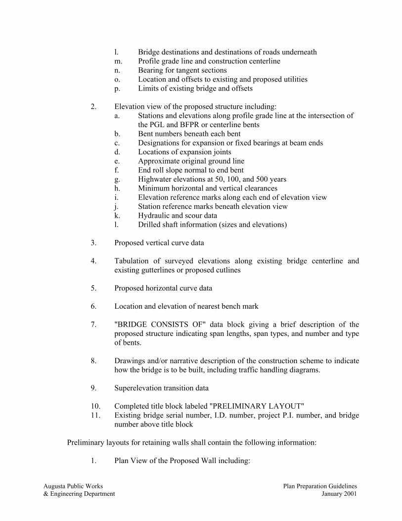
Augusta Public Works Plan Preparation Guidelines& Engineering Department January 2001
l. Bridge destinations and destinations of roads underneathm. Profile grade line and construction centerlinen. Bearing for tangent sectionso. Location and offsets to existing and proposed utilitiesp. Limits of existing bridge and offsets
2. Elevation view of the proposed structure including:a. Stations and elevations along profile grade line at the intersection of
the PGL and BFPR or centerline bentsb. Bent numbers beneath each bentc. Designations for expansion or fixed bearings at beam endsd. Locations of expansion jointse. Approximate original ground linef. End roll slope normal to end bentg. Highwater elevations at 50, 100, and 500 yearsh. Minimum horizontal and vertical clearancesi. Elevation reference marks along each end of elevation viewj. Station reference marks beneath elevation viewk. Hydraulic and scour datal. Drilled shaft information (sizes and elevations)
3. Proposed vertical curve data
4. Tabulation of surveyed elevations along existing bridge centerline andexisting gutterlines or proposed cutlines
5. Proposed horizontal curve data
6. Location and elevation of nearest bench mark
7. "BRIDGE CONSISTS OF" data block giving a brief description of theproposed structure indicating span lengths, span types, and number and typeof bents.
8. Drawings and/or narrative description of the construction scheme to indicatehow the bridge is to be built, including traffic handling diagrams.
9. Superelevation transition data
10. Completed title block labeled "PRELIMINARY LAYOUT"11. Existing bridge serial number, I.D. number, project P.I. number, and bridge
number above title block
Preliminary layouts for retaining walls shall contain the following information:
1. Plan View of the Proposed Wall including:

Augusta Public Works Plan Preparation Guidelines& Engineering Department January 2001
a. Beginning and ending wall stations and offsets. The station and offsetshall also be given at every break point along the horizontalalignment of the wall.
b. Limits of the right-of-way shall be indicated by station and offset.c. Location and size of any utilities, drainage pipes, noise barriers, light
standards, and overhead signs.
2. Elevation View of the Proposed Wall includinga. Elevations on top of the wall (parapet or traffic barrier) at the
beginning and ending of the wall and at profile break points.b. The existing and proposed ground elevations at the bottom and top of
the wall as well as a footing envelope which shall indicate the highestelevation the footing for an earth wall can be located.
c. Location and size of any utilities, drainage pipes, noise barriers, lightstandards, and overhead signs
3. Narrative of any construction staging which may be required to erectthe wall.
B. Final Bridge PlansThe final plans represent the continued development of the structure conceptas it was presented in the preliminary drawings. During the preparation ofthese plans, the engineer must assess every aspect and component of thebridge and adequately convey his or her design thoughts through descriptivedrawings of each element.Construction plans shall contain all dimensions, notes, and details necessaryfor a contractor to prepare a bid and construct the structure. Constructionplans for the bridges usually contain some or all of the following sheets.
a. Plan and Elevation Sheetsb. General Notes Sheetsc. Construction Sequence Sheetsd. Deck Plan Sheetse. Deck Section Sheetsf. Framing Plan Sheetsg. Steel Beam Sheets
h. Prestressed Concrete Beam Sheetsi. Neoprene Bearing Sheetsj. Miscellaneous Details Sheetsk. Intermediate Bent Sheetsl.. End Bent Sheetsm. As-Built Foundation Information Sheetsn. Bar Reinforcement Details Sheets

Augusta Public Works Plan Preparation Guidelines& Engineering Department January 2001
Required information for each of the above sheets is given in the following section.Additional sheets should be provided as necessary to show the details required forconstruction. This may include plans for the provision of utilities, pier protection,special bridge deck joints, overhead signs and roadway lighting on the bridges.Several of these sheets may be incorporated into the roadway plans. Coordinatepreparation with the roadway designers.
III. SHEET LAYOUTPrepare bridge and structural plans either electronically on a CAD system or using pencil orink on mylar. Draw plans to scale whenever possible.
Use standard "D" sized plan sheets. Use Department standard title blocks placed at the lower right corner of each plan sheetincluding standard revision block, header block, scale, date, and initial blocks. Size, label,and format according to current Department practice. Place the sheet designation (title) firstin the main body of each title block followed by the structural description in terms ofnumerical road designations. List the county and project number along the bottom edge ofthe main body.
Place "BRIDGE SHEET _ OF _" or other structural sheet number designations directly tothe left of the title block and along the bottom edge of drawing area.
Use Department standard roadway sheet designation blocks placed at the upper right cornerof each plan sheet. Size, label, and format according to current Department practiceshowing state, project number, roadway sheet number, and total number of plan sheets.Information about specific plan sheets is as follows:A. Plan and Elevation Sheets
All bridge and structural plans are required to have plan and elevation sheets.As a minimum, the plan and elevation sheets for bridge plans should containthe following information:
1. Plan view of the proposed structure including:a. Begin and end bridge stationsb. Centerlines of bents, BFPR's, and skew anglesc. Length of spans and full length of bridged. Width gutter to gutter and out to oute. Width of sidewalks and parapets and/or barriersf. Width of roadways beneath structureg. Intersection stations and angles of roadways beneathh. Flow direction or ebb & flood tide directions and approximate edge
of bank lines at normal flowi. Milepost numbers, stations, and intersection angles at
railroadsj. Location of point of minimum vertical clearancek. Horizontal clearances from edges of travelway beneath to nearest
proposed faces of substructure

Augusta Public Works Plan Preparation Guidelines& Engineering Department January 2001
l. North arrowm. Bridge destinations and destinations of roads underneathn. Profile grade line and construction centerlineo. Bearing for tangent sectionsp. Location and offsets to existing and proposed utilitiesq. Wingwalls with pile blocks if applicabler. Removal lines for wideningss. Temporary barrier and/or shoringt. Limits of slope paving and/or rip rapu. Limits of existing bridge and offsets
2. Elevation view of the proposed structure including:
a. Stations and elevations along profile grade line at the intersection ofthe PGL and BFPR or centerline bents
b. Bent numbers beneath each bentc. Designations for expansion or fixed bearings at beam endsd. Locations of expansion jointse. Approximate original ground linef. End roll slope normal to end bentg. Highwater elevations at 50, 100, and 500 yearsh. Minimum horizontal and vertical clearancesi. Footings and seals with elevationsj. Piles in intermediate pile footings (note end bent piles not shown)k. Pile encasements and elevations where required
3. Proposed vertical curve data
4. Tabulation of surveyed elevations along existing bridge centerline andexisting gutterlines or proposed cutlines
5. Proposed horizontal curve data
6. Superelevation transition data
7. Slope paving details and/or rip rap details8. Completed title block labeled "PLAN AND ELEVATION"
9. Existing bridge serial number, I.D. number, project P.I. number, and bridgenumber above title block
B. General Notes Sheets
Use General Notes sheets following plan and elevation sheets. Use standardGa.D.O.T. format.
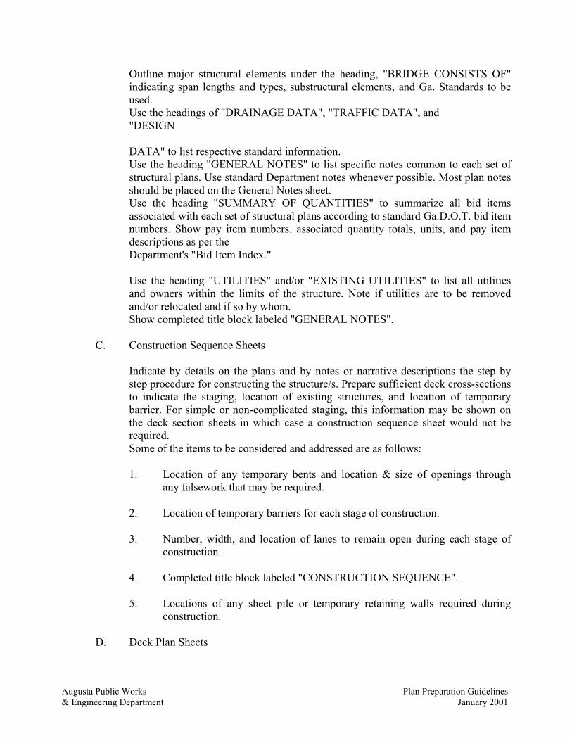
Augusta Public Works Plan Preparation Guidelines& Engineering Department January 2001
Outline major structural elements under the heading, "BRIDGE CONSISTS OF"indicating span lengths and types, substructural elements, and Ga. Standards to beused.Use the headings of "DRAINAGE DATA", "TRAFFIC DATA", and "DESIGN
DATA" to list respective standard information.Use the heading "GENERAL NOTES" to list specific notes common to each set ofstructural plans. Use standard Department notes whenever possible. Most plan notesshould be placed on the General Notes sheet.Use the heading "SUMMARY OF QUANTITIES" to summarize all bid itemsassociated with each set of structural plans according to standard Ga.D.O.T. bid itemnumbers. Show pay item numbers, associated quantity totals, units, and pay itemdescriptions as per the Department's "Bid Item Index."
Use the heading "UTILITIES" and/or "EXISTING UTILITIES" to list all utilitiesand owners within the limits of the structure. Note if utilities are to be removedand/or relocated and if so by whom.Show completed title block labeled "GENERAL NOTES".
C. Construction Sequence Sheets
Indicate by details on the plans and by notes or narrative descriptions the step bystep procedure for constructing the structure/s. Prepare sufficient deck cross-sectionsto indicate the staging, location of existing structures, and location of temporarybarrier. For simple or non-complicated staging, this information may be shown onthe deck section sheets in which case a construction sequence sheet would not berequired.Some of the items to be considered and addressed are as follows:
1. Location of any temporary bents and location & size of openings throughany falsework that may be required.
2. Location of temporary barriers for each stage of construction.
3. Number, width, and location of lanes to remain open during each stage ofconstruction.
4. Completed title block labeled "CONSTRUCTION SEQUENCE".
5. Locations of any sheet pile or temporary retaining walls required duringconstruction.
D. Deck Plan Sheets

Augusta Public Works Plan Preparation Guidelines& Engineering Department January 2001
Follow General Notes sheets and if used, Construction Sequence sheets with DeckPlan sheets for bridge plans. As a minimum, deck plan sheets should contain thefollowing information:
1. Plan view of each unique span including:a. Handrails and/or barriers & joint spacingb. Endpostsc. Endwalls, diaphragms, & edgebeams and sizesd. Diaphragm spacing (layout) unless shown on Beam Chord Layoutsheete. Beams and beam centerlinesf. Paving restg. BFPR & Centerline Bentsh. Profile Grade Line & Construction Centerlinei. Length of spans measured along inside face of barrier or parapetj. Width of bridge gutter to gutter & out to outk. Skew angles between tangent to Construction Centerline &
Centerline Bent or BFPRl. Transverse dimensions labeled radial for curvem. Expansion & construction jointsn. Longitudinal deck & barrier rebar and lap lengthso. Fanned deck rebar in acute corners for skewed spansp. Continuity of steel to each side of centerline for continuous bent (use
continuous or lapped 600 bar)
2. Quantity Table (prefer quantity block to lower right) showing correct class ofconcrete, bar reinforcing steel, and labeled for each span or pour.
3. Expansion and/or construction joint details (label "req'd" as necessary)
4. Barrier transition details
5. Sections thru endwalls, diaphragms, and edgebeams
6. "T" dimensions for reinf. conc. deck girder bridges
7. Completed title block labeled "DECK PLAN
E. Deck Section Sheets
Follow Deck Plan sheets with Deck Section sheets for all bridge structures. Showsection views cut across the structure indicating all horizontal dimensions necessaryto construct the bridge. As a minimum, the Deck Section sheets should contain thefollowing information:

Augusta Public Works Plan Preparation Guidelines& Engineering Department January 2001
1. Sections thru deck slab and at edgebeams, diaphragms, and endwalls and/orcrossframes including:a. Deck reinforcement near midspan and if different, at intermediate
bentsb. Reinforcement in edgebeams, diaphragms, and endwallsc. Reinforcement in beam stems of reinf. conc. deck girdersd. Connection details, member & plate sizes of crossframese. Correct welding symbolsf. Centerline bridge, const. centerline and profile grade lineg. Width gutter to gutter & out to outh. Width of barrier and/or sidewalk & parapeti. Depth of sidewalk at parapet face & at gutterlinej. Tie pour dimensions, cutlines, & const. jointsk. Beam spacings and overhang dimensionsl. Deck slab thicknesses and cross-slopem. Drip bead details along overhangsn. Top of deck to top of beam dimensions at centerline bearingso. Beam stem depth & width for reinf. conc. deck girdersp. Bearings and preformed joint filler under endwallsq. Preformed "foam" joint filler between brng. pads and endwallsr. Utilities and utility opening details thru edgebeams, diaphragms, and
endwallss. Conduit details thru slab or barrierst. Special deck pouring sequences and/or pour rates
2. Crown ordinate detail
3. Longitudinal & section details of beam reinforcement & dimensions forreinforced concrete deck girder stems
4. Barrier and/or sidewalk & parapet details
5. Deck drain or scupper details
6. Utility hanger details7. Completed title block labeled "DECK SECTIONS"
F. Framing Plan Sheets
Provide framing plans for bridges with curved alignments or variable widths.Prepare drawings to show a single, concise graphical representation of all thegeometric control necessary for the location and detailing of beam or girdersuperstructure framing.Show sufficient information to permit the verification or determination of allcalculated, detailed dimensional or noted information on the drawings related to thebeam or girder layout as well as other work related or dependent upon the layout.

Augusta Public Works Plan Preparation Guidelines& Engineering Department January 2001
Show completed title block labeled "FRAMING PLAN".
G. Steel Beam SheetsAs a minimum, steel beam sheets should contain the following information:
1. Elevation view of each unique beam including:
a. Overall length of beamb. Dimensions to centerline of bearings and bents and/or BFPRc. Sizes of plates or rolled beam designationsd. Location and spacing of stiffeners and shear connectors
2. Beam grade and camber ordinate diagram
3. Dead load deflections
4. Stiffener details
5. Shear connector details
6. Welding and/or bolting details
7. Safety handrail detail
8. Notes as follows:
a. Type of steel required for each memberb. Main load carrying members subject to tensile stress and Charpy V-
notch test requirementsc. Camber grades are measured at bottom of top flanged. Camber compensates for total dead load deflection and effects of
vertical curve
9. Completed title block labeled "STEEL BEAM DETAILS - SPAN"H. Prestressed Concrete Beam Sheets
The Department has developed standard prestressed concrete beam sheets. Use thesesheets or a similar format whenever possible. As a minimum, prestressed concretebeam sheets should contain the following information:
1. Elevation view of beams placed at upper left of sheet including:
a. Overall length of each beam and spanb. Dimensions to centerline of bearings and bents and/or BFPRc. Non-composite and composite dead load deflectionsd. Location of diaphragm holes

Augusta Public Works Plan Preparation Guidelines& Engineering Department January 2001
e. Location of low friction hold down/sf. Shear stirrup spacings & bursting reinforcingg. Prestressing steel
2. Section views at midpoint and end of beam (place at same height andimmediately to the right of elevation view) including:a. Flange and web dimensionsb. Strand pattern, raised distance and/or sheathingc. Bar reinforcing and cover requirements
3. Individual bar reinforcement details
4. Recess detail for diaphragm rods
5. Flange clip detail when necessary
6. Notes as follows:a. Beam handling and pick-up requirementsb. Chamfer edges of beams 1/2" or 3/4"c. Horizontal dimensions are in place dimensions and are to be adjusted
for grade and fabrication effectsd. Location of fixed & exp. joints and bearing chase sizese. Finishing requirements along top flangef. Composite & non-composite deflection criteriag. Strand requirements and specificationsh. Prestressing data (Number of strands, type, prestress force per strand,
release strength of concrete, total jacking force, and net prestressforce after losses)
i. Concrete design strength (f'c)
7. Completed title block labeled "PSC BEAM (type) - SPAN _"
I. Neoprene Bearing SheetsThe Department has developed standard bearing sheets for neoprene bearing pads.Use these sheets or a similar format whenever possible. As a minimum, neoprenebearing sheets should contain the following information:
1. Plan view of bearing pad and beveled shim plates including:a. Beam and pad centerlinesb. Overall dimensions and dimensions to centerlinesc. Hole for dowel bar
2. Plan and section view of bearing pad under beam including:a. Beam, pad, and bent capb. Edge clearancec. Preformed foam and preformed joint filler
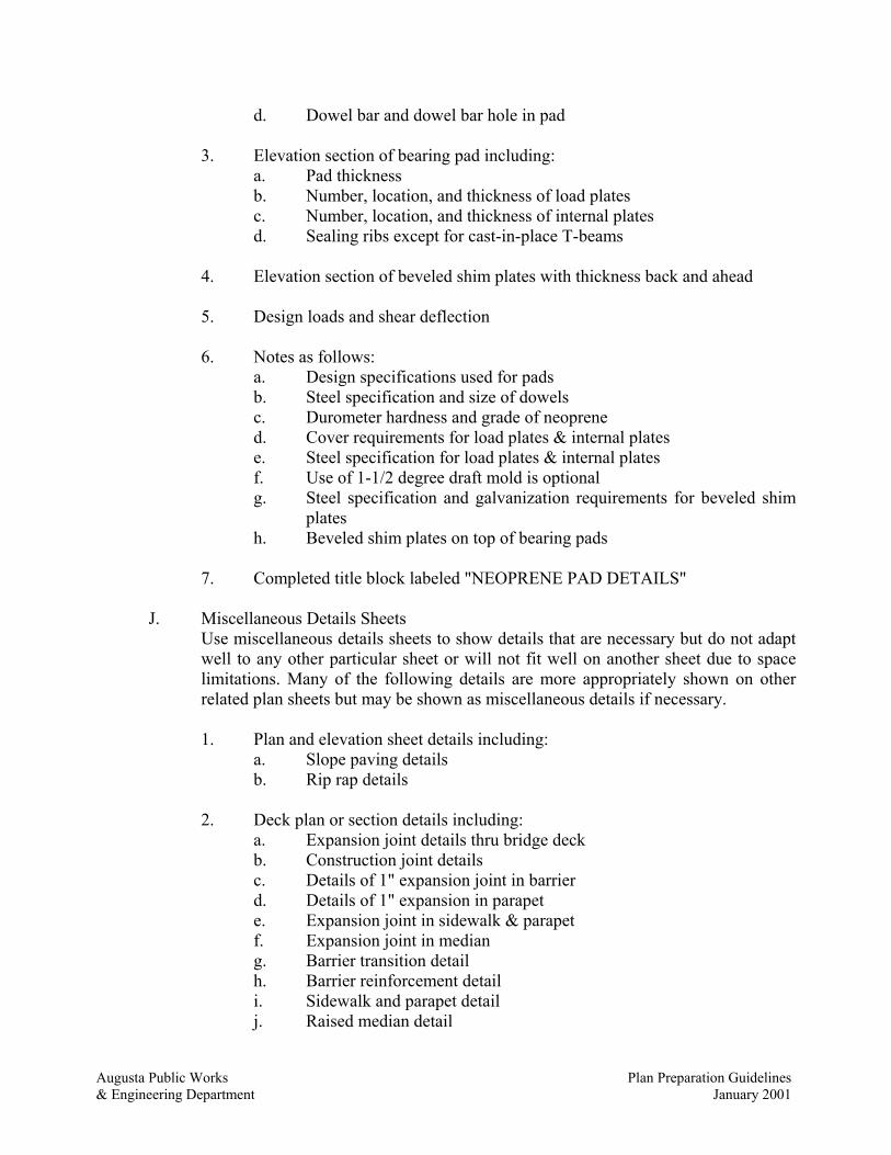
Augusta Public Works Plan Preparation Guidelines& Engineering Department January 2001
d. Dowel bar and dowel bar hole in pad
3. Elevation section of bearing pad including:a. Pad thicknessb. Number, location, and thickness of load platesc. Number, location, and thickness of internal platesd. Sealing ribs except for cast-in-place T-beams
4. Elevation section of beveled shim plates with thickness back and ahead
5. Design loads and shear deflection
6. Notes as follows:a. Design specifications used for padsb. Steel specification and size of dowelsc. Durometer hardness and grade of neoprened. Cover requirements for load plates & internal platese. Steel specification for load plates & internal platesf. Use of 1-1/2 degree draft mold is optionalg. Steel specification and galvanization requirements for beveled shim
platesh. Beveled shim plates on top of bearing pads
7. Completed title block labeled "NEOPRENE PAD DETAILS"
J. Miscellaneous Details SheetsUse miscellaneous details sheets to show details that are necessary but do not adaptwell to any other particular sheet or will not fit well on another sheet due to spacelimitations. Many of the following details are more appropriately shown on otherrelated plan sheets but may be shown as miscellaneous details if necessary.
1. Plan and elevation sheet details including:a. Slope paving detailsb. Rip rap details
2. Deck plan or section details including:a. Expansion joint details thru bridge deckb. Construction joint detailsc. Details of 1" expansion joint in barrierd. Details of 1" expansion in parapete. Expansion joint in sidewalk & parapetf. Expansion joint in mediang. Barrier transition detailh. Barrier reinforcement detaili. Sidewalk and parapet detailj. Raised median detail
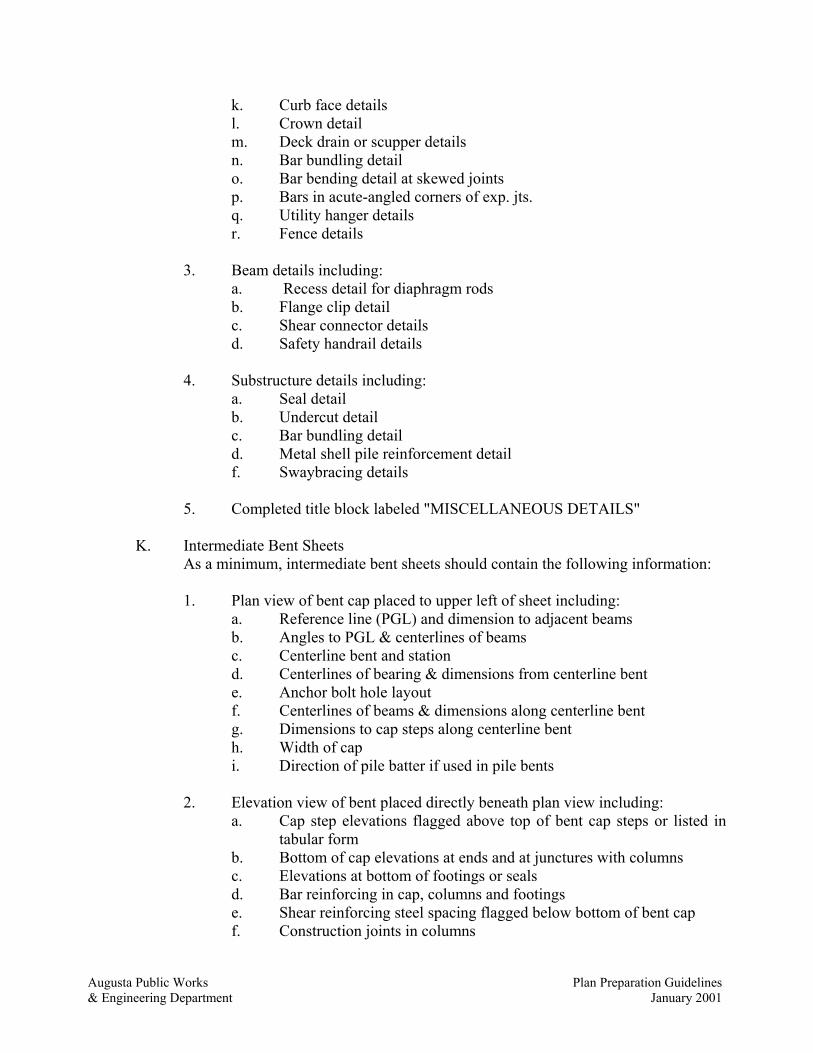
Augusta Public Works Plan Preparation Guidelines& Engineering Department January 2001
k. Curb face detailsl. Crown detailm. Deck drain or scupper detailsn. Bar bundling detailo. Bar bending detail at skewed jointsp. Bars in acute-angled corners of exp. jts.q. Utility hanger detailsr. Fence details
3. Beam details including:a. Recess detail for diaphragm rodsb. Flange clip detailc. Shear connector detailsd. Safety handrail details
4. Substructure details including:a. Seal detailb. Undercut detailc. Bar bundling detaild. Metal shell pile reinforcement detailf. Swaybracing details
5. Completed title block labeled "MISCELLANEOUS DETAILS"
K. Intermediate Bent SheetsAs a minimum, intermediate bent sheets should contain the following information:
1. Plan view of bent cap placed to upper left of sheet including:a. Reference line (PGL) and dimension to adjacent beamsb. Angles to PGL & centerlines of beamsc. Centerline bent and stationd. Centerlines of bearing & dimensions from centerline bente. Anchor bolt hole layoutf. Centerlines of beams & dimensions along centerline bentg. Dimensions to cap steps along centerline benth. Width of capi. Direction of pile batter if used in pile bents
2. Elevation view of bent placed directly beneath plan view including:a. Cap step elevations flagged above top of bent cap steps or listed in
tabular formb. Bottom of cap elevations at ends and at junctures with columnsc. Elevations at bottom of footings or sealsd. Bar reinforcing in cap, columns and footingse. Shear reinforcing steel spacing flagged below bottom of bent capf. Construction joints in columns

Augusta Public Works Plan Preparation Guidelines& Engineering Department January 2001
g. Column spacing dimensioned along centerline benth. Width of columns and footingsi. Thickness of footingsj. Piles for pile footings and embedment into footingsk. Pile batter if usedl. Drilled shaft information (sizes and elevations)
3. Cap and column section views for each different cross-section placed toupper left of sheet including:a. Vertical and horizontal dimensionsb. Main reinforcing steel layouts in cap sections and columnsc. Distribution reinforcement along vertical face of capd. Vertical shear reinforcement stirrups in cape. Horizontal tie reinforcement in columnsf. Anchor bolt holes with dimensionsg. Reinforcement steel cover
4. Pile layout for pile footings including:a. Footing outline with dimensionsb. Longitudinal and transverse pile spacings and dimensions to edges of
footingc. Dimensions referenced to centerline column and centerline bentd. Direction of traffice. Direction of pile batter if used
5. Quantity table (prefer quantity table to lower right) with correct class ofconcrete, bar reinforcing steel, and labeled for each individual bent
6. Plan Driving Objective noting pile size & type, required driving resistance,and minimum tip elevation
7. Allowable bearing capacity note & key detail if spread footing
8. Seal detail if required and assumed water surface elevation note
9. Undercut detail if required
10. Metal shell pile reinforcement detail if required11. Completed title blocklabeled "BENT _"
L. End Bent SheetsAs a minimum, end bent sheets should contain the following information:
1. Plan view of bent cap placed to upper left of sheet including:a. Reference line (PGL) and dimension to adjacent beamsb. Angles to PGL, centerlines of beams, and wingwalls

Augusta Public Works Plan Preparation Guidelines& Engineering Department January 2001
c. BFPR and stationd. Centerlines of bearing & dimensions from centerline bente. Anchor bolt hole layoutf. Centerlines of beams & dimensions along centerline bentg. Dimensions to cap steps & piles along front face of caph. Width and length of capi. Width and length of wingwallsj. Dimensions of wing fillets and pile blocks if usedk. Bar reinforcing in cap, wingwalls, and pile blocksl. Direction of pile batter if used
2. Elevation view of bent placed directly beneath plan view including:a. Cap step elevations flagged above top of bent cap steps or listed in
tabular formb. Bottom of cap elevations at junctures with inside face of wingwallsc. Elevations at back and ahead top face of wingwalld. Construction joints and rebar lapse. Main reinforcing in capf. Stirrup or tie spacingg. Pile spacing dimensioned along front face of caph. Piles embedded into bent capi. Pile batter if usedj. Drilled shaft information (sizes and elevations)
3. Cap section views for each different cross-section placed to upper left ofsheet including:a. Vertical and horizontal dimensionsb. Main reinforcing steel layoutsc. Distribution reinforcement along vertical face of capd. Vertical stirrups or tiese. Reinforcement steel coverf. Anchor bolt holes with dimensionsg. Piles and pile embedment into cap
4. Notes as follows:a. Clearance of reinforcement is 5 cm unless otherwise notedb. Pour cap and wing monolithicallyc. Bottom of wing is leveld. Wing piles not shown in elevation view
5. Quantity table (prefer quantity table to lower right) with correct class ofconcrete, bar reinforcing steel, and labeled for each individual bent
6. Plan Driving Objective noting pile size & type, required driving resistance,and minimum tip elevation

Augusta Public Works Plan Preparation Guidelines& Engineering Department January 2001
7. Metal shell pile reinforcement detail if required
8. Completed title block labeled "BENT _"
M. As-Built Foundation Information SheetsAs-built foundation information sheets are required in all sets of bridge plans. Theyprovide a blank form for the project engineer to fill in as the foundation workprogresses so an as-built record of footing, seal, and pile tip elevations can beobtained. Place this sheet/s at the end of each set of bridge plans just prior to the barreinforcing details sheets.As a minimum, as-built foundation information sheets should contain the following:
1. Plan views of each different footing including:a. Pile or caisson layoutb. Piles or caissons labeled left to right, back to ahead, starting over
with each individual footingc. Piles or caissons labeled by beam number for piles in end bents and
pile bentsd. Wingwall piles labeled "Right" and "Left", "Back" and "Ahead"
2. Table of "AS-BUILT FOUNDATION INFORMATION"a. Bent numbersb. Pile or caisson numbersc. Pile or caisson tip elevationsd. Elevations at bottom of footings or bottom of seals
3. Elevation view of concrete footings
4. Standard as-built note, (NOTE - THIS "AS-BUILT FOUNDATIONINFORMATION" SHEET IS TO BE FILLED IN BY THE PROJECTENGINEER AND THE ENTIRE SHEET FORWARDED TO THEBRIDGE OFFICE UPON COMPLETION OF FOOTINGCONSTRUCTION FOR POSTING TO THE PLANS AS A PERMANENTRECORD OF THE BRIDGE CONSTRUCTION) placed directly above titleblock
5. Completed title block labeled "AS-BUILT FOUNDATIONINFORMATION"
N. Bar Reinforcement Details SheetsThe Department has developed a standard sheet format (table) for showing barreinforcing details based on GA STD 3901 and computer generated output. Use thisstandard sheet format. Use the Department's computer program, "RBAR", togenerate the standard bar reinforcement tables and quantities whenever possible.Organize the rebar tables by grouping bars according to bar location (span, pour,bent, etc.) first, then by bar mark in ascending order. Show span or pour bars first
Augusta Public Works Plan Preparation Guidelines& Engineering Department January 2001
starting at the beginning of the structure and working toward the end. Follow withsubstructure bars in a like manner.As a minimum, leave one blank line between each group of bars of a different sizeand leave two blank lines between each location group.Show special bar details of bar types not shown on GA STD 3901 in the blank areagenerally located along the right side of each sheet (above title block). Label thesespecial bars "Type 60", "Type 61", etc. as needed and dimension them appropriatelyin the bar tables.Show completed title block labeled "BAR REINFORCEMENT DETAILS".
O. Retaining Wall PlansIn addition to the information shown on the preliminary wall layout drawings, thefollowing information shall be included in the final plans:
1. Final location and size of any feature which may effect the construction ofthe wall including: noise walls, overhead signs, drainage structures, androadway lighting.
2. Indicate the final superelevation of the roadway(s) associated with thewall(s) construction.
3. A narrative of any construction staging which may be required to erect thewall.
4. The top of footing elevation based on a minimum cover.5. Complete structural details showing a sufficient number of plans, elevations
and sections with all dimensions necessary to construct the wall.
6. A table of quantities listing all of the pay items and their quantities that arenecessary to bid the wall.
7. Completed title block.
IV. MISCELLANEOUS NOTES & OTHER INFORMATIONAll construction plans and documents designed, detailed, and furnished by consulting firmsfor Department use shall bear a valid Professional Engineer stamp. All plans submitted tothe Department for review shall have been checked by the plan preparer prior tosubmission.

Augusta Public Works Plan Preparation Guidelines& Engineering Department January 2001
CHAPTER 18"GEORGIA STANDARD DRAWINGS" and SPECIAL DETAILS
I. GENERAL"Georgia Standard Drawings" are generalized construction drawings that are applicable tomost construction projects. Special detail sheets are usually included in the plans set if theproject involves areas which require special attention to some construction elements. Showconstruction details that are not included in the GDOT's Standards and Construction Detailson the special details sheet. This sheet shall be prepared on standard plan format. Anyconvenient scale may be used, provided the information shown is clear and legible at halfsize reduction of plans. Details shown shall be clear, legible, labeled, complete in allrespects and should be adequately cross-referenced to the plans in the plans set.
Typical special details by the Department or other entities may be used if approved and asshown as special details.
Standard Drawings and Standard Construction Details - Copies or computer diskscontaining all of the GDOT's standards and standard construction details may be acquiredfrom the GDOT's "Office of Road Design" during normal business hours.Special Construction Details - Special construction detail drawings should include alldimensions, details, clearances, and components clearly presented. No sole-sourcecomponents can be made a part of the detail. Represent all manufacturers' components asspecific models "or equal." Show, or document in the special provisions for each item, themethod of payment, general detail notes, specific methods of construction, finishes, etc.

Augusta Public Works Plan Preparation Guidelines& Engineering Department January 2001
CHAPTER 19SPECIAL PROVISIONS
I. GENERALA Special Provision is a modification to the current "Standard (or applicablesupplemental) Specifications for Construction of Roads and Bridges." A SpecialProvision will be required on any project where proposed work is not covered underthe current specifications, or is being modified. Include in the Special Provision thedescription of work, materials, construction, measurement and payment. In general,use the same format as that used for the Standard Specifications.

Augusta Public Works Plan Preparation Guidelines& Engineering Department January 2001
CHAPTER 20RIGHT-OF-WAY PLANS
I. GENERALRight-of-Way plans are necessary for the acquisition of the required right-of-way andeasements for the project.Proper representation of the right of way and easements are required to ensure their properlegal interpretation for property acquisition and deed description as well as limits ofconstruction activities and potential environmental and property concerns.Prepare preliminary right-of-way plans after addressing the comments from the 30% PlanReview.
II. REQUIRED INFORMATIONThe following requirements are considered as a minimum for the preparation of right-of-way plans. Additional information may be required to be included on the plans over andabove that hereinafter outlined due to the nature of the Project.
A. Delineation - Important features of the Right-of-Way plans must be clearly shown.These include right-of-way lines, easement limits, property lines, improvements,parcel identification numbers, and dimensions. Place these and other pertinentmatters on the plans so that they are readily distinguishable and easily read andidentified.
B. Size of Plans - Prepare the detail plans and cover sheets on mylar using the samesize and scale requirements as for the construction plans.
C. Property Lines - Locate and depict the property lines accurately and concisely on theplans with adequate ties to the centerline and required right-of-way so that a legaldescription can be drawn for the deeds and condemnations. Clearly show the nameof the owner or owners for each parcel. Dimensions and bearings on property linesoutside the right-of-way are not to be shown except by plotting to scale; however,dimensions and bearings on property lines within the right-of-way shall be clearlyand accurately shown in area tables for each parcel. If the property line is comprisedof a horizontal curve, then show the arc length, chord length, chord bearing andradius of curve for the property line in the tables as well. Show the back propertylines on all parcels on the cover sheet. Provide coordinates for a minimum of twopoints only on the centerline, baseline or tangent, on each sheet.
D. Improvements and Culture Indicate all pertinent data that may affect the cost of theright-of-way on the plans. Some of these include structures, roads, streams, ponds,city limits, orchards, fences, wells, septic tanks, sewage field lines, springs,commercial signs on or near the required right-of-way and various improvements.

Augusta Public Works Plan Preparation Guidelines& Engineering Department January 2001
Show any improvements located outside the Right-of-Way that might have aninfluence on the appraised value to scale on the plan sheet.
E. Right-of-Way - Place all permanent structures and facilities which requiremaintenance by the Department on right-of-way or permanent easements. Sufficientright-of-way will be acquired to allow for necessary construction and maintenance,and every effort should be made to make the right-of-way as uniform as possible.Exceptions to this requirement will be considered pending approval by theDepartment.
F. Easements - Show required easements accurately on the plans. Adequatelydimension easements in the area tables utilizing station and offsets so that they canbe precisely located on the ground. Show the areas of all easements, exceptdriveway easements in square feet and. Large easements (over 1 acre) in rural areasmay be shown in acres.Clearly label the easement as to use, such as for slopes, drainage, or as a detour, asappropriate. Label easements for a type of construction that does not requiremaintenance by the Department as: "Easement for the construction of____________" with the actual purpose of the easement being specified on theplans. Examples of this type of construction are channel changes, driveways, yarddrains, tree wells, steps and sidewalks leading into residences or places of business,and to provide a working area outside of the right-of-way where constructionactivities require it. This type of easement will expire upon completion and finalacceptance of the project for which acquired.Label easements for a type of construction that will require future maintenance bythe Department as: "Easement for the construction and maintenance of_________________". An example of this type of construction is a retaining wall tieback system.
G. Subdivisions - In subdivisions, show the remaining property to scale. In cases wherethe back of the lots cannot be shown to scale, a break may be shown on the propertylines with the distance to the back of the lot shown approximately in meters. It maybe necessary, in some instances, to include inserts on the right-of-way detail plan toadequately show information pertinent to the individual lots. The subdivision maybe shown on the cover sheet as an outline of the entire subdivision with a notation asto the parcels included. Show all roads or streets, including names, on the detail planor cover sheet.
H. Railroad Crossings - Tie the intersections with the centerline of railroads into theroadway centerline by station and angle. Show the width of the right-of-way, nameof railroad, each track by symbol and distance, and direction along the railroad right-of-way to the nearest mile post number.
I. Intersecting Roads and Existing Streets - Tie the intersection of all paved andmaintained public roads by station and angle and equated to the station of the surveyof the intersected road. Show the name of the road, state and federal routes, if any,

Augusta Public Works Plan Preparation Guidelines& Engineering Department January 2001
and the right-of-way width of the road. Provide details of private roads and accessroads to parking lots and commercial centers on the Right-of-Way plans. A thoroughinvestigation shall be made to establish accurately the existing right-of-way of allintersecting roads and the existing Right-of-Way of roads parallel to the proposedproject. If no record of the existing right-of-way can be found, then show the area being maintained as the existing right-of-way.
J. Limited Access - On limited access projects, including partial limited access, showthe access control lines by the conventional limited access symbols. In areas wherethe limited access line and the right-of-way lines are in the same location indicateboth. Indicate the exact beginning and ending of limited access at interchanges orcrossroads with an arrow and the symbols E L/A or B L/A and the station and offsetas appropriate. Clearly indicate any intermediate breaks in the limited access. Wherethe Right-of-Way and limited access lines coincide, label as "Required right-of-way& Limit of Access."
K. Parcel Numbers - Assign a parcel number to each parcel for which right-of-way,easement (any type) or access rights is being acquired starting with parcel one at thebeginning of right-of-way acquisition and numbering consecutively through the endof right-of-way acquisition. Assign a separate parcel number for adjoining parcelsunder the same ownership. If it is necessary later to split a parcel or anotherownership is found, additional parcels may be shown by adding a suffix of A, B, etc.to the number of an adjacent parcel. Parcel numbers are usually assigned during thepreliminary plans phase. These numbers cannot change after the preliminary plansubmittal. Parcel numbers may be added or deleted as described herein but notchanged or rearranged. Where additional right-of-way is to be acquired in the nameof a utility company for relocating its facilities, use the right-of-way parcel numberwith a suffix designating the utility company (such as 39 GP for Georgia Power or18 SB for Southern Bell). If an additional land owner is involved, solely forrelocating the utility facility, then use an individual parcel with the proper suffix. Onurban projects involving city blocks, the numbering of parcels for some projectsmay be facilitated by giving each block an alphabetical designation and thennumbering each parcel in the block numerically. The use of this alphabeticaldesignation procedure shall be determined on an individual project basis. Foradvertising signs which are to be purchased, relocated, or damaged identify with thesame parcel number as the tract upon which they are located followed by the letter"S". If more than one sign is located on a parcel, then identify as follows: 17-S-1,17-S-2, etc.
L. Areas - The areas of required right-of-way, the remainder on the left, and theremainder on the right shall be shown in the right-of-way tables for each parcel. Usethe symbols: RR = Area Remaining on the Right of the Right-of-Way Line and RL= Area remaining on the Left of the Right-of-Way Line. In preparing right-of-wayplans, do not refer to area taken as "take" or the letter "T" but refer to as "RequiredRight-of-Way" or "Req'd right-of-way". Show the area for each tract of requiredright-of-way for a parcel in square feet and square meters and also in acres and
Augusta Public Works Plan Preparation Guidelines& Engineering Department January 2001
hectares. Compute the needed area in acres to the third decimal with the remainingareas to be shown to the nearest one hundredth (0.01) acre for areas under one acre,to the nearest tenth (0.1) acre for areas between one acre and ten acres, and to thenearest acre for areas in excess of ten acres. During the appraisal review process, if adetermination is made by the Department that a parcel remainder is an uneconomicremnant, the plans shall be revised as follows:Required right-of-way remains the same.Label the property lines of the remnant "Limit of Property Acquisition".Identify the remnant area using the subject parcel number with an "R" suffix. If aparcel has more than one remnant then use the "R" suffix with a number. Forexample: Parcel 35 has two remnants. Therefore, indicate each remnant as 35-R1and 35-R2.The area breakdown of such a parcel could be shown as follows:Area Required.Rem.35.15.375 Ac. (right-of-way) 29 Ac. (RL)35-R1 0.662 Ac.35-R20.300 Ac. 16.337 Ac. (Total)
M. Cover Sheet - Prepare cover sheets for right-of-way plans using the samerequirements as for construction plans. Include a "Length of Project" box on thesheet. The length of the right-of-way project is not necessarily the same as theconstruction project length, but is to be the actual length of the right-of-way project.When the beginning or ending stations are different, left or right, then the greaterlength shall always be used; and in every case it is the beginning and ending of therequired right-of-way and/or easements. Provide a revision block on the cover sheetso all revisions on the detail sheets can be listed on the cover sheet. The cover sheetrevision block is to indicate revision date and sheet numbers only. Include on thecover sheet beginning and ending stations of the right-of-way project includinglimits of right-of-way acquisition on all side roads, parcel numbers, existing andrequired right-of-way lines and labels, project termini of construction contracts, anorth arrow, graphic scale of cover sheet, date of plan completion, project locationsketch, signature block for State Highway Right-of-Way Engineer, note stating theplans were prepared under the supervision of the Department's liaison and, ifavailable, land lot lines and numbers, Land Districts or Georgia Militia Districts. Seethe detailed check list in Chapter 22 for additional requirements.
N. Property Map - Typically the property map is a part of the cover sheet. If a separateproperty map is required, then prepare a right-of-way property map or propertymaps at a scale that adequately reflects property lines, roads, streets, and otherappropriate culture after the sheet is reduced to letter size or legal size. Show on theproperty map the full property lines of large property holdings, and if property lineswould extend beyond the limits of the map, broken property lines may be shown. Itis usually necessary to indicate the entire property so that all access roads to theproperty can be shown for the benefit of the appraiser and reviewing appraiser.Show the parcel number for each parcel having required right-of-way and/oreasements. Show the right-of-way project number in the title block and at the topright corner of the sheet. Provide a north arrow in the upper right corner and agraphic scale near the lower right corner of the drawing.

Augusta Public Works Plan Preparation Guidelines& Engineering Department January 2001
III. PLAN LAYOUTA. General Information for Plan Sheets - Include the following information on each
plan sheet, in addition to that previously mentioned:
1. The construction centerline and any other related centerlines, clearly labeledwith street mainline, State Route and U.S. No.'s), stations, bearings andcurve numbers.
2. The construction limits (labeled or provide legend, include cut (c) and fill (f) symbols), based upon approved preliminary plan, profile, andcross sections.
3. Title Block. The project number and date in each title block with sheetsnumbered.
4. Edges of pavement (existing and proposed), median locations and drivewaylocations.
5. North arrow and scale.
6. Revision blocks with space for dates and brief description of revision.
7. Right-of-way legends.
8. Curve data tables.
9. Major drainage such as culverts, channel changes; particularly all outfallsthat affect right-of-way and/or require easements.
10. Survey control points.
11. Owner's names, parcel numbers, construction limits, existing and requiredright-of-way lines and labels, easement lines and labels, right-of-way andeasement point numbers used in area computations.
12. Land Lot Numbers and lines (shown and labeled); Land District Numbersand lines (shown and labeled); G.M.D. Numbers and lines, if applicable(shown and labeled).Also, indicate the Land Lot and Land District No.'s thatoccur on each individual sheet at the lower right corner of the sheet abovethe title block.
13. Full stations and offsets for driveway easement points. If a drivewayeasement point occurs where there is already a right-of-way or othereasement point that has a point number shown on the plans and therefore hasthe station and offset shown in an area table, then the station and offset need

Augusta Public Works Plan Preparation Guidelines& Engineering Department January 2001
not be shown on the plan. Also, if more than one centerline is used, statewhich centerline the information is taken from or provide a general note.
14. Existing and required limits of access labeled or provide legend. ProvideBLA and ELA with station and offset at access break points.
15. Show begin/end each project for dual project plans.
16. Begin and end right-of-way acquisition.
17. "Legend" for L/A, Existing and Required right-of-way, Property Lines,Construction Limits, Easements and any other symbols used on the plans, asrequired in Memo No. 12 dated 8/12/89.
18. Angles and stations where centerlines cross streets.
19. Equality stations (if any).
20. Any utility relocation.
21. Dual County projects - Show only the County pertaining to that individualsheet in the title block. Flag the County line station on the centerline.
22. Show City limits if applicable.
23. Provide coordinates for two points only on the centerline for each plan sheet.These points should be reference points such as PC's, PT's, side streetcenterline intersections or railroad intersections. If reference points are notavailable, use even stations.
24. Right-of-Way from railroads should be referenced from both the centerlineand to the nearest railroad milepost. Provide coordinates. See the latestDepartment RR MOG.
25. Locating the railroad milepost applies to all areas of right-of-way andeasement which are not contiguous.
26. Label all property line with the "pl" symbol.
27. Label all buildings if data is available.
28. Show all signs, gas pump islands, gas tanks, septic tanks, sewage field linelocations and permanent light fixtures. Locate and annotate signs within therequired right-of-way.

Augusta Public Works Plan Preparation Guidelines& Engineering Department January 2001
29. Reference parcel numbers to other plan sheet(s) necessary to cover the entireparcel.
30. When more than one tract of required right-of-way exists for a parcel, labeleach as Tract 1, Tract 2, etc... on the plan sheet(s) where the tract occurs.
31. Label all easements and hatch according to the legend. Do not placeeasements closer than 15 feet from the centerline of the tracks on railroadparcels.
B. General Information for Area Tables - Include the following information in theright-of-way and easement area computation tables, in addition to that previouslymentioned. If sufficient space is available, then place the required area tables on theright-of-way plan sheets. If space is not available on the right-of-way plan sheetsthen provide a separate sheet immediately following the plan sheet containing thearea tables for the parcels on the preceding plan sheet. Provide references on theplan sheets that indicate the location of the sheet where the tables can be found andvice versa.
1. Provide point number, English offset, station and alignment taken from foreach point needed to compute the area of required right-of-way or easement(excluding driveway). Provide English distance and bearing between eachpoint described above. A separate area computation will be provided for eachtract of required right-of-way and easement (excluding driveway).
2. Provide arcs, radii, chord length and chord bearing for all curved linesbetween points in feet and meters. Exception: Bearings are not required onexisting right-of-way lines.
3. Indicate the area of required right-of-way in square feet and acres and squaremeters and hectares.
4. Indicate the area of required easements (excluding driveway) in square feetand square meters.
5. Show separate areas for each remainder for parcels with remainders on eachside of the project or cross street. Provide a remainder or the total lot size forparcels with easement acquisition only (except driveway).
6. For parcels with access rights only, no required right-of-way nor easements,provide parcel number, owner, linear feet of access rights and parcelremainder (total area).
7. If a parcel has more than one tract of required right-of-way then each tractshall be labeled as Tract 1, Tract 2, etc. Provide the above information for alltracts. In the area table for the last tract indicate the required area for that

Augusta Public Works Plan Preparation Guidelines& Engineering Department January 2001
tract, the total area of required right-of-way for the parcel and the remainderleft and right.
8. If a parcel has more than one tract of required easement area then indicatethe required easement area for all tracts. Indicate the type of easement. In thearea table for the last tract indicate the required area for that tract, the totalrequired easement for the parcel for each type easement (except driveway).Note: Do not assign a tract number for easements.
9. Keep all the separate tract areas for an individual parcel grouped together.
IV. MISCELLANEOUS NOTES & OTHER INFORMATIONA. Other Requirements - The following are additional items which the plan preparer
shall follow in the preparation of right-of-way plans:
1. Make sure that linework and text on plans are dark enough to show onblueline prints and on a reduced letter size print. Property lines andconstruction lines should clearly stand out.
2. Full station and plus shall be used on all right-of-way, easement, andproperty lines rather than the plus only.
3. Do not shade right-of-way plans.4. Do not begin or end (if possible) projects in the middle of a parcel if there is
to be a Future project.
5. Do not show the linear feet or meters of access rights on parcels where thereis required right-of-way.
6. Do not use the same symbol for driveway easement and constructioneasement.
7. Do not leave off the North Arrow, Remainders, Construction Limits, orStations and Offsets.
8. When plan sheet is revised, revision block shall include date, initials ofresponsible engineer, and brief description of the revision.
9. Describe tracts in a clockwise direction to facilitate deed writer's description.
B. Sources of Information - The sources of information that should be utilized incompiling data for the preparation of right-of-way plans are numerous. Some of theinformation required for right-of-way plans cannot be economically obtained byregular survey parties. It may be necessary to research additional sources to obtainthe needed information to complete the right-of-way plans. It may be necessary tocheck with the Clerk of Court's Office, Planning and Zoning, and/or Development

Augusta Public Works Plan Preparation Guidelines& Engineering Department January 2001
and Inspections, for information in regard to subdivisions, commercialdevelopments, and property transactions. Ownership shall be formally determinedfrom the preliminary title check. Aerial mapping furnished by the Department andthose available at the County Agent's Office are often valuable in locating propertylines, land lot lines, access roads, streams, ponds, and various other improvements.County Engineers and the City Engineers may have reference maps which provideadditional data. The U.S. Geological Survey, the U.S. Forest Service, and the U.S.Coast and Geodetic Survey maps can furnish pertinent information. In preparingplans for urban projects, city tax maps shall be examined. The railroad evaluationmaps shall be obtained and compared if railroad company right-of-way limits appearto be within the required project right-of-way. Utility company maps shall becompared for data concerning their easements. Right-of-way plans are a legaldocument and sometimes end up in court, so the information must be as accurate aspossible. The plan preparer is responsible for utilizing whatever data necessary toprepare an accurate set of right-of-way plans
C. Number of Copies Submitted - Submit two sets of blueline prints to the Departmentfor preliminary review. The Department will review the plans for conformance withthe criteria set forth herein. Upon receipt of the Department's review commentsmake all necessary corrections. Then, resubmit one sets of mylar prints, two set ofblueline prints and the original marked review set from the Department for furtherreview and approval by the Department. After all corrections resulting from reviewsare made and the right-of-way plans are ready for approval, submit the originalcover sheet to the Department for approval.
D. Revisions - Revisions to the right-of-way plans are noted on the plans only after theplans have been approved and signed by the Department. Revisions will bedocumented as follows:
1. In the revision block on the sheet where the revision occurs note the date ofeach revision and a brief description of each revision.
2. On the cover sheet in the revision block note the date of the revision and thesheet number(s) where the revision(s) occurs.
Sometimes a revision will require an additional sheet to the plans. When thishappens, the date on the additional sheet must match the "Plans Completed" date onthe cover sheet. On the cover sheet in the revision block note the date the sheet wasadded and the new sheet number. In the revision block on the additional sheet notethe date the sheet was added to the plans and indicate in the description that this isan additional sheet.
E. Requirements for Exhibit Plats - When required, exhibit plats shall be prepared foreach individual parcel involving required right-of-way and/or required easementsnecessary to construct the project. These plats shall be for the County's use in

Augusta Public Works Plan Preparation Guidelines& Engineering Department January 2001
preparing legal deed descriptions and agreements for right-of-way acquisition. Thescale for exhibit plats shall be the same as the right-of-way plans.The plat size shall be not larger than 11x17 (8½ 14 preferred if readable), and shallinclude the following:
1. Station and offsets at all points
2. Metes and bounds defining required right-of-way and permanent easementsand temporary easements
3. North arrow
4. Area for required right-of-way
5. Easements labeled (temporary construction, utility, guardrail, driveways,others as directed by the Department)
6. Easement areas in square feet (with temporary and permanent denotedseparately)
7. Parcel number
8. Owner
9. Building labeled
10. Access rights
11. Access breaks (also show dimension of access breaks and driveways)
12. Signs, fences
13. Gas islands, pump tanks, and permanent light fixtures at service stations, anyimprovements
14. Scale
15. Sealed by a registered land surveyor in the State of Georgia
16. Sources of property information (i.e., field surveys, tax maps, deed booknumber and page number)
17. Land lot and tax map parcel numbers.
F. Required Line Weights and Text Sizes - The basic format for the right-of-way planswill be same as for the roadway plans. There are, however, elements that appear on

Augusta Public Works Plan Preparation Guidelines& Engineering Department January 2001
the right-of-way plans that are not found on the roadway plans, such as metes andbounds. For easement cross hatch patterns and line codes, refer to the standardlegend placed on each right-of-way plan sheet.The minimum text size for right-of-way plans is 3.5 mm (1.75 m on a 1:500 scale).Standard pen and text sizes for right-of-way plans are as follows:Element Pen/Text Size---------------------------------------------------------------Construction Baseline Wt. 4 / solid Existing right-of-way Wt.3 / long dash - short dash Proposedright-of-way Wt. 4 / solid Proposed Edges of Pavement Wt. 2 / solid ExistingTopo/Background Per the Department's Guidelines Property Line Wt.3 / long dash -short dash Easement Line Wt. 2 / solid Easement Cross Hatch Wt. 0 / varies Construction Limits Wt. 2 / longDash Street Names, 500' Stations, Wt. 3 / 5.2 mm (2.6 m @ 1:500 scale) Begin andEnd Project Stations, Equalities Property Owner, Parcel Number Wt. 2 / 5.2 mm (2.6m @ 1:500 scale) Land Lot, District, Tax Map Parcel No.Stations and Offsets,Metes and Wt. 1 / 3.5 mm (1.75 @ 1:500 scale) Bounds, Bearings, Area Required,

Augusta Public Works Plan Preparation Guidelines& Engineering Department January 2001
CHAPTER 21DOCUMENTATION of DESIGN and QUANTITIES
I. GENERALPrepare documentation of all design calculations and quantity takeoffs in design booklets.Organize quantity takeoffs, with subtotals, by plan sheet for easy transfer to the "Summaryof Quantity" sheets. Show the total quantity for each pay item on the last takeoff sheet forthat pay item. Record all design computations and computer printouts neatly on letter sizesheets. Fully title, date, number and index all sheets.Prepare hydraulic study reports consistent with DGOT drainage manual guidelines. Includethe roadway drainage analysis and any computer printouts that document the size ofdrainage structures.Prepare separate volumes for quantity takeoffs, roadway design calculations, bridge designcalculations and hydraulic studies for submittal. Each of these volumes may be broken outinto separate columns if required by the number of pages.
II. SUGGESTED FORMAT FOR QUANTITY TAKEOFFSAll design calculations and quantity takeoffs shall be documented in a design booklet.Calculations shall be checked and verified for applicability to the proper pay item, andsigned off by both the originator and reviewer. Quantity takeoffs should be organized on aper plan sheet format for easy transfer to the "Summary of Quantity" sheets. Side streetquantities, if shown separately, should include all quantities to the normal outside edge ofpavement of the mainline roadway. Separate sheets should be used for each item and thetotal quantity for each pay item shall be tallied and shown on the last takeoff sheet for thatpay item.The use of spreadsheets for tabulating quantity takeoffs is recommended. Electronicspreadsheets can reduce math errors and can be linked to CAD drawings for ease of inputinto the "Summary of Quantity" sheets.Use the following forms, or some similar form approved by the Department, to tabulatequantities. Separate forms are provided based upon the type of units involved with thedifferent pay items.

Augusta Public Works Plan Preparation Guidelines& Engineering Department January 2001
CHAPTER 22CHECKLISTS
I. GENERALUse checklists to ensure the completeness of the design and to ensure the designer's intent isproperly represented. Checklists should be utilized not only for formal or intermediatesubmittals but throughout the design process. Included herein are examples of checkliststhat could be used.
The goal of the project team shall be to produce a set of plans for construction that is ofhigh quality and containing ZERO DEFECTS. Using checklists in conjunction with astandard checking procedure will minimize production costs and reduce technical problems,construction Change Orders and the occurrence of liability claims.
Quality cannot be added on at the end, it must be built into the overall development of theproject and must be attended to throughout the entire life of the project.