Embed Size (px)
Citation preview
STRUCTURAL DESIGN
PLAN. DESIGN. SUSTAIN.
Seero is a professional multi- disciplinary firm that provides design, engineering, consultancy, and construction management services
Our Services
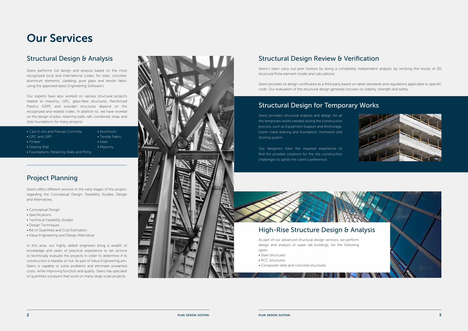
Seero performs full design and analysis based on the most
recognized local and international codes, for steel, concrete,
aluminum elements, cladding, pure glass and tensile fabric
using the approved latest Engineering Software’s.
Our experts have also worked on various structural projects
related to masonry, GRC, glass-fiber structures, Reinforced
Plastics (GRP), and wooden structures depend on the
recognized and related codes. In addition to, we have worked
on the design of piles, retaining walls, raft, combined, strap, and
strip foundations for many projects.
Seero’s team carry out peer reviews by doing a completely independent analysis, by verifying the results of 3D
structural finite element model and calculations.
Seero provides its design certificated as a third party based on latest standards and regulations applicable to specific
code. Our evaluation of the structural design generally focuses on stability, strength and safety.
Seero offers different services in the early stages of the project,
regarding the Conceptual Design, Feasibility Studies, Design
and Alternatives,
• Conceptual Design
• Specifications
• Technical Feasibility Studies
• Design Techniques
• Bill of Quantities and Cost Estimation
• Value Engineering and Design Alternative
In this area, our highly skilled engineers bring a wealth of
knowledge and years of practical experience to set actions
to technically evaluate the projects in order to determine if its
construction is feasible or not. As part of Value Engineering aim,
Seero is capable to solve problems and eliminate unwanted
costs, while improving function and quality. Seero has specialist
of quantities surveyors that work on many large-scale projects.
In this area, our highly skilled engineers
bring a wealth of knowledge and
years of practical experience to set
actions to technically evaluate the
projects in order to determine if its
construction is feasible or not.
As part of Value Engineering aim,
Seero is capable to solve problems
and eliminate unwanted costs, while
improving function and quality.
Seero has specialist of quantities
surveyor that work on many
Structural Design & Analysis Structural Design Review & Verification
Project Planning
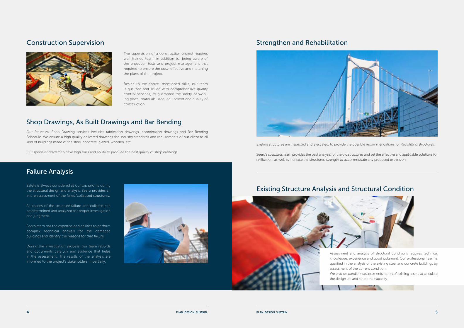
As part of our advanced structural design services, we perform
design and analysis of super tall buildings, for the following
types:
• Steel structures
• RCC structures
• Composite steel and concrete structures.
High-Rise Structure Design & Analysis
Structural Design for Temporary WorksSeero provides structural analysis and design for all
the temporary works needed during the construction
process, such as Equipment Support and Anchorage,
tower crane bracing and foundation, formwork and
shoring system.
Our designers have the required experience to
find the possible solutions for the site construction
challenges to satisfy the client’s preference.
• Cast in situ and Precast Concrete • Aluminum
• GRC and GRP • Tensile Fabric
• Timber • Steel
• Glazing Wall • Masonry
• Foundations, Retaining Walls and Piling
PLAN. DESIGN. SUSTAIN. PLAN. DESIGN. SUSTAIN.2 3
Strengthen and Rehabilitation
Existing Structure Analysis and Structural Condition
Construction Supervision
Failure Analysis
The supervision of a construction project requires
well trained team, in addition to, being aware of
the producer, tests and project management that
required to ensure the cost- effective and matching
the plans of the project.
Beside to the above- mentioned skills, our team
is qualified and skilled with comprehensive quality
control services, to guarantee the safety of work-
ing place, materials used, equipment and quality of
construction.
Existing structures are inspected and evaluated, to provide the possible recommendations for Retrofitting structures.
Seero’s structural team provides the best analysis for the old structures and set the effective and applicable solutions for
ratification, as well as increase the structures’ strength to accommodate any proposed expansion.
Assessment and analysis of structural conditions requires technical
knowledge, experience and good judgment. Our professional team is
qualified in the analysis of the existing steel and concrete buildings by
assessment of the current condition.
We provide condition assessments report of existing assets to calculate
the design life and structural capacity.
Safety is always considered as our top priority during
the structural design and analysis. Seero provides an
entire assessment of the failed/collapsed structures.
All causes of the structure failure and collapse can
be determined and analyzed for proper investigation
and judgment.
Seero team has the expertise and abilities to perform
complex technical analysis for the damaged
buildings and identify the reasons for that failure.
During the investigation process, our team records
and documents carefully any evidence that helps
in the assessment. The results of the analysis are
informed to the project’s stakeholders impartially.
Our Structural Shop Drawing services includes fabrication drawings, coordination drawings and Bar Bending
Schedule. We ensure a high quality delivered drawings the industry standards and requirements of our client to all
kind of buildings made of the steel, concrete, glazed, wooden, etc.
Our specialist draftsmen have high skills and ability to produce the best quality of shop drawings
Shop Drawings, As Built Drawings and Bar Bending
PLAN. DESIGN. SUSTAIN. PLAN. DESIGN. SUSTAIN.4 5
Scope:Structural design for B+G+F+P VVIP villa with a plot limit area 1522.1 m2, in Doha, Qatar.
Private Villa
Description:
Highness Engineering Consultants have assigned Seero Engineering Consulting to prepare the structural design and
Quantities surveying for a unique villa consists of basement, Ground floor, first floor, and penthouse, the villa has a
top roof swimming pool and GYM.
CLIENTHighness Engineering
Consultants
LOCATIONDoha, Qatar
GFA1522.1 sqm
SERVICEStructural Design
Al Wakra Beach Renovation North and South
Description:
Bin Omran Trading and Contracting (BOTC), has assigned Seero Engineering Consulting to carry out a Structural
design for all the main beach facilities on Al Wakra Beach, including Cafeterias, Toiles, Generator Rooms, Guard
Rooms, and Water Tanks Room.
In addition to design the light poles and wooden Sun-Shades’ foundations to resist the expected high wind load.
Scope:Structural Design for all the beach facilities including the
cafeterias, toilets, generator rooms, water tank rooms,
Guard rooms, wooden Sun Shades and septic tanks.
CLIENTBin Omran Trading and Contracting (BOTC)
LOCATIONAl Wakra, Qatar
SERVICEStructural Design
PLAN. DESIGN. SUSTAIN. PLAN. DESIGN. SUSTAIN.6 7
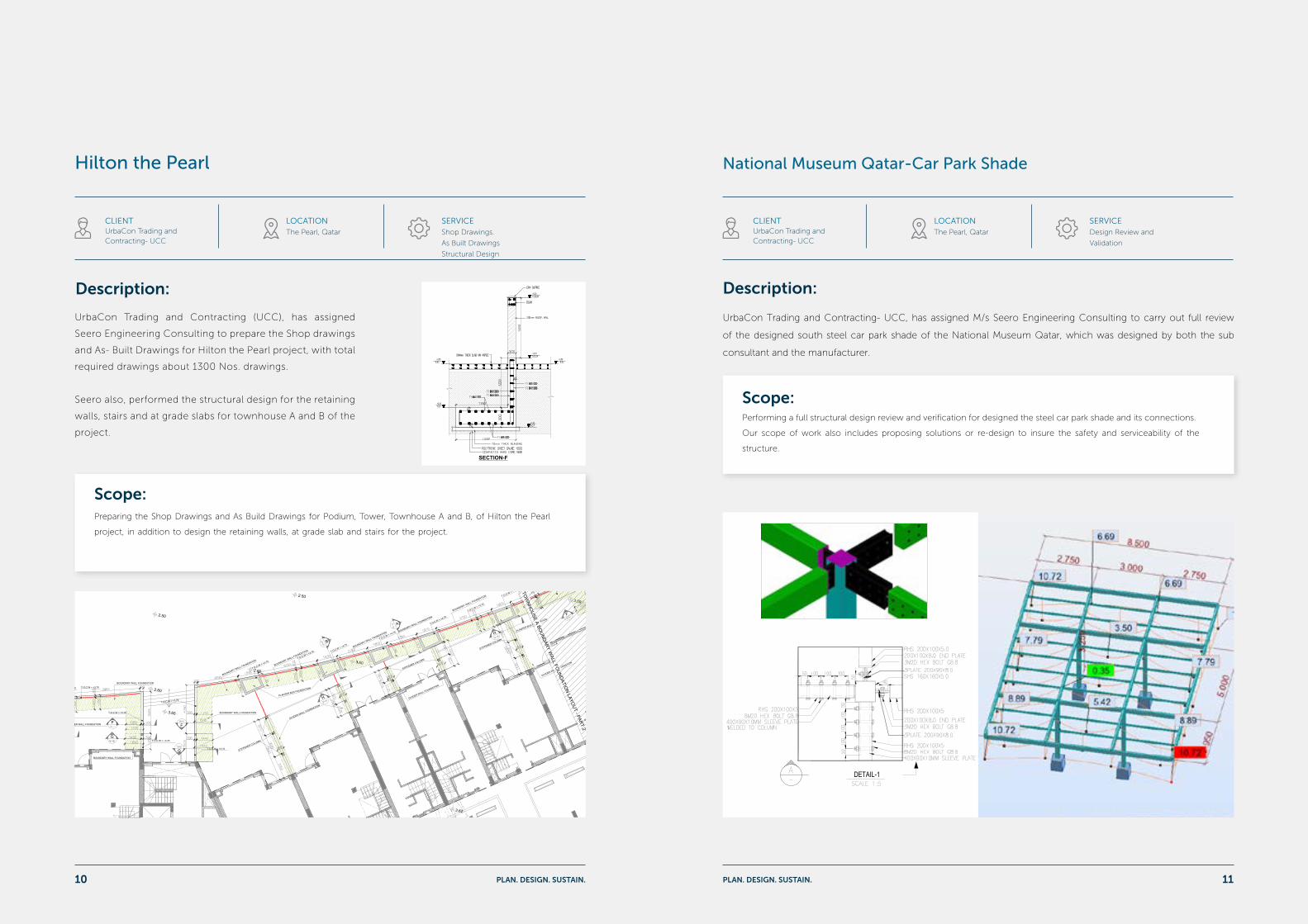
Scope:Structural design for a Commercial Building (B+G2+F) with a plot limit area 1011 sqm, in Nuaija, Qatar.
Mixed Use & Commercial Building
Description:
Ismail Bin Ali Group (IBA) has appointed Seero Engineering Consulting to carry out the structural design, quantities
surveying, Specifications, and drafting for a commercial building in Nuaija, Qatar.
The building consists of Basement, and ground floor for rental shops, beside 2 typical floors divided into apartments
for rent.
CLIENTIsmail Bin Ali Group (IBA)
LOCATIONNuaija, Qatar
GFA1011 sqm
SERVICEStructural Design
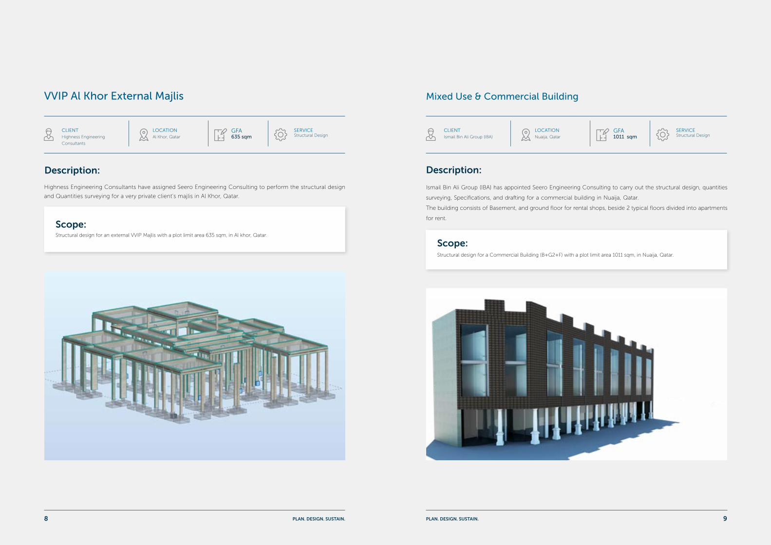
CLIENTHighness Engineering
Consultants
LOCATIONAl Khor, Qatar
GFA635 sqm
SERVICEStructural Design
VVIP Al Khor External Majlis
Description:
Highness Engineering Consultants have assigned Seero Engineering Consulting to perform the structural design
and Quantities surveying for a very private client’s majlis in Al Khor, Qatar.
Scope:Structural design for an external VVIP Majlis with a plot limit area 635 sqm, in Al khor, Qatar.
PLAN. DESIGN. SUSTAIN. PLAN. DESIGN. SUSTAIN.8 9
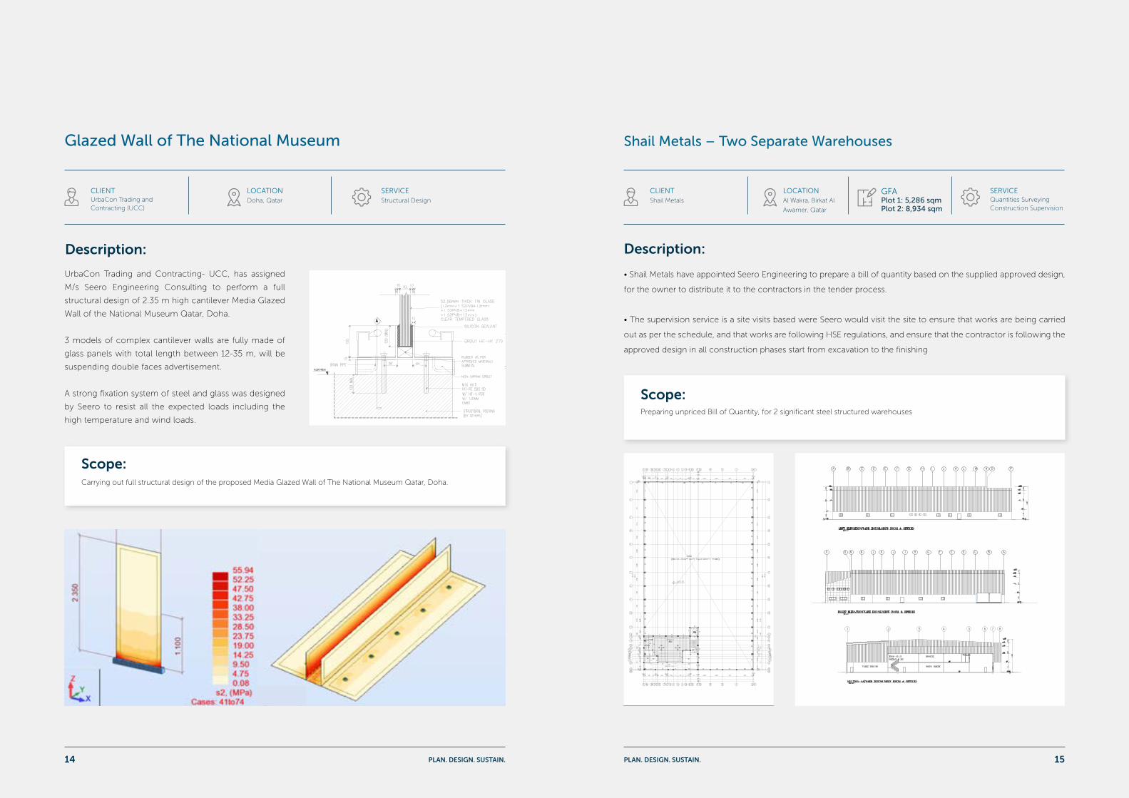
Scope:Performing a full structural design review and verification for designed the steel car park shade and its connections.
Our scope of work also includes proposing solutions or re-design to insure the safety and serviceability of the
structure.
National Museum Qatar-Car Park Shade
Description:
UrbaCon Trading and Contracting- UCC, has assigned M/s Seero Engineering Consulting to carry out full review
of the designed south steel car park shade of the National Museum Qatar, which was designed by both the sub
consultant and the manufacturer.
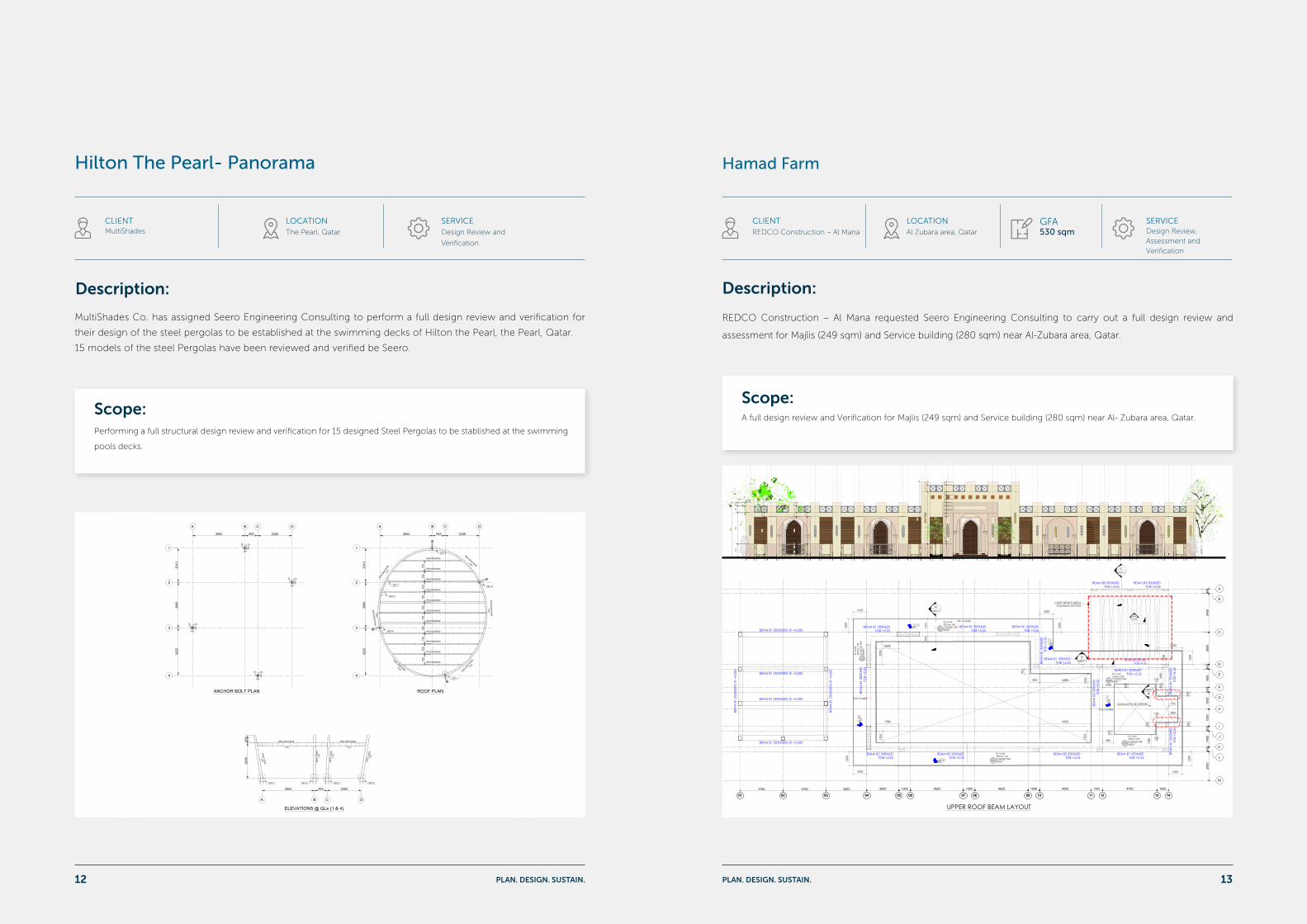
Hilton the Pearl
Description:
UrbaCon Trading and Contracting (UCC), has assigned
Seero Engineering Consulting to prepare the Shop drawings
and As- Built Drawings for Hilton the Pearl project, with total
required drawings about 1300 Nos. drawings.
Seero also, performed the structural design for the retaining
walls, stairs and at grade slabs for townhouse A and B of the
project.
Scope:Preparing the Shop Drawings and As Build Drawings for Podium, Tower, Townhouse A and B, of Hilton the Pearl
project, in addition to design the retaining walls, at grade slab and stairs for the project.
2.60
3.60
3.60
2.60
3.65
2.50
2.60
2.50
3.602.75
3.25
3.00
3.50
3.62
3.47 3.65 3.62
3.47
3.65
3.34
3.49
3.47
3.62
3.47
3.62
BOUNDARY WALL FOUNDATION
BOUNDARY WALL FOUNDATION
BOUNDARY WALL FOUNDATION
BOUNDARY WALL FOUNDATIONPLANTER BOX FOUNDATION
BOUNDARY WALL FOUNDATION
BOUNDARY WALL FOUNDATION
BOUNDARY WALL FOUNDATION
BOUNDARY WALL FOUNDATION
BOUNDARY WALL FOUNDATION BOUNDARY WALL FOUNDATION
BOUNDARY WALL FOUNDATION
BOUNDARY WALL FOUNDATION
PLANTER BOX FOUNDATION
PLANTER BOX FOUNDATION
T.O.C.W = +3.70
T.O.C.W = +3.70 T.O.C.W = +3.70T.O.C.W = +4.70 T.O.C.W = +4.70
T.O.C.W = +4.70
T.O.C.W = +4.70
T.O.C.W = +4.70
T.O.C.W = +4.70
T.O.C.W = +4.70
T.O.C.W = +3.70
T.O.C.W = +3.70
T.O.C.W = +3.70
T.O.C.W = +3.70
T.O.C.W = +3.70
T.O.C.W = +3.70
T.O.C.W = +3.70
T.O.C.W = +3.70
T.O.C.W = +3.70
T.O.C.W = +3.70
T.O.C.W = +3.70
STIFFENER COLUMN
STIFFENER COLUMN
A
C
B
D
E
A
B
FF
F
G
G
DIVIDER WALL FOUNDATION
DIVIDER WALL FOUNDATION
DIVIDER WALL FOUNDATION
DIVIDER WALL FOUNDATION
DIVIDER WALL FOUNDATION
STIFFENER COLUMN
STIFFENER COLUMN
STIFFENER COLUMN
H
H
H
3.623.62
3.65
3.60
2.55
2.60
2.60
3.60
3.60
3.65
2.60
3.60
BOUNDARY WALL FOUNDATION
BOUNDARY WALL FOUNDATION
BOUNDARY WALL FOUNDATION
BOUNDARY WALL FOUNDATION
BOUNDARY WALL FOUNDATION
BOUNDARY WALL FOUNDATION
PLANTER BOX FOUNDATION
T.O.C.W = +4.70T.O.C.W = +4.70
T.O.C.W = +4.70
T.O.C.W = +3.70
T.O.C.W = +3.70 T.O.C.W = +3.70
T.O.C.W = +3.70
T.O.C.W = +3.70
T.O.C.W = +3.70
T.O.C.W = +3.70
T.O.C.W = +3.70
T.O.C.W = +3.70
A
B
F F
DIVIDER WALL FOUNDATION DIVIDER WALL FOUNDATION
DIVIDER WALL FOUNDATION
STIFFENER COLUMN
STIFFENER COLUMN
STIFFENER COLUMN
H
H
GENERAL NOTES:
This document is property of KCT. Unilateral modification is prohibited. Partial or total use, the reproductionor conceding to third parties of this document require prior express authorisation by the authors.
HILTON - THE PEARLABRAJ QUARTIER, TOWER AQ-07 AND TOWNHOUSES
THE PEARL- QATAR
KEY PLAN
N
NORTH SIGN
K E O I n t e r n a t i o n a l C o n s u l t a n t sC R i n g R o a d , O p p A l m a n a B l d gP . O . B o x 1 8 1 0 8, D o h a , Q a t a rT 9 7 4 4 6 2 6 4 0 0
WZMH ARCHITECTS
ARCHITECTURALSTRUCTURALMECHANICAL
SUPERVISIONELECTRICAL
W L LTEL:44 363813-4 P.O.B: 5785-QATAR , 44 360764-5 FAX:44 363812
Quilligan ArchitectsArchitecture, Interior & Urban Designers56 Camden Street Lower, Dublin 2T: +353 1 4782800 F: +353 1 4782800 [email protected]
I N T E R N A T I O N A L A R C H I T E C T S
THE PEARL 9 7 4 4 3 5 5 2 1 9F 9 7 4 4 3 6 1 5 4 2TD o h a , Q a t a r
P . O B o x 7 2 5 6U n i t e d D e v e l o p m e n t C o m p a n y
O W N E R :
Project:
Client & Engineer
Original Designer - Concept Architect :
Original Designer - Architects & Engineering Of Record :
Supervision Consultant:
Consultant:
Local Architect
Main Contractor:
Project Management Consultancy PMC:
KCT532 SDS
Seero Engineering Consulting
Office No. 2 & 3,1st floor,Building 128Al Jazeera Al Arabia Street 362Madinat Khalifa (Zone 34)P.O. Box: 201257Doha, QATAR.Tel: (+974) 44866821Fax: (+974) 44866410Email: [email protected]: www.seeroeng.com
Scale 1:100
TOWNHOUSE A BOUNDARY WALL FOUNDATION LAYOUT (PART 1)1
Scale 1:100
TOWNHOUSE A BOUNDARY WALL FOUNDATION LAYOUT (PART 2)2
TOW
NH
OU
SE
A B
OU
ND
AR
Y W
ALL
FO
UN
DA
TIO
N L
AY
OU
T - P
AR
T 1
TOW
NHOUSE A BO
UNDARY WALL FO
UNDATION LAYO
UT - PART 2
1. THIS DRAWING IS TO BE READ WITH RELEVANT ARCHITECTURAL & STRUCTURAL DRAWINGS.
2. ALL DIMENSIONS ARE IN MILLIMETER AND LEVELS ARE IN METER UNLESS NOTED OTHERWISE.
3. BOUNDARY WALL , DIVIDER WALL & FOUNDATIONS HAVE BEEN DESIGNED FOR AN ASSUMED SAFE SOIL BEARING CAPACITY OF 150KN/m² ,
ANGLE OF SOIL TO BE 25° & BULK DENSITY OF SOIL IS 18 IF FOUND OTHERWISE,THE FOUNDATION SHALL BE REDESIGNED TO SUIT SITE
CONDITIONS. IT IS THE RESPONSIBILITY OF THE CONTRACTOR TO MAKE TRAIL PITS & OTHER TESTS AT HIS ON COST AND INFORM THE
CONSULTANTS ABOUT THE SITE CONDITIONS FOR TAKING NECESSARY ACTIONS.
4. A MINIMUM CUBE CRUSHING STRENGTH OF 35KN/mm² AND STEEL GRADE 500Mpa(N/mm²) FOR CONCRETE ABOVE & UNDER GROUND IS
REQUIRED.
5. COVER REINFORCEMENT FOR R.C BELOW AND ABOVE GROUND ARE AS MENTIONED:
BELOW GROUND (FOUNDATION) = 75mm
BELOW GROUND (GROUND BEAM) = 50mm
SLAB ON GRADE = 25mm
6. ALL EXPOSED FACES IN CONTACT WITH GROUND/EARTH ARE TO BE PAINTED WITH TWO COATS OF BITUMINOUS PAINT & SHALL BE
PROTECTED WITH A LAYER OF 1000G POLYTHENE SHEET.
7. MINIMUM LAP FOR TENSION & COMPRESSION REINFORCEMENTS CONFORMING TO ACI-318 SHALL BE PROVIDED.
8. MIN. THICKNESS OF SLAB ON GRADE 150mm , UNLESS OTHERWISE SPECIFIED.
9. TESTING OF CEMENT. FINE AGGREGATED, COARSE AGGREGATE, BLOCKS , ELECTRICAL, PLUMBING AND PERCOLATION TEST OF
CONCRETE ETC. SHALL BE CARRIED OUT BY THE CONTRACTOR AT HIS COST AS CARRIED BY THE CONSULTING ENGINEER.
10. CONCRETE SHALL ALWAYS BE READY MIXED AND NO CONCRETE SHALL BE USED WHICH HAS REMAINED UNPLACED FOR MORE THAN THE
SPECIFIED TIME BY THE MANUFACTURER. VIBRATION OF CONCRETE IS ESSENTIAL UNTIL THE APPEARANCE OF AIR BUBBLES ON THE
SURFACE OF CONCRETE CEASES. DURING THE FIRST.
11. ALL WORK SHOULD COMPLY WITH ACI-318 & QCS 2014 OR AS DIRECTED BY CONSULTING ENGINEER.
12. ALL MATTERS CONNECTED TO THIS WORK, THE DECISION OF CONSULTING ENGINEER IS FINAL AND BINDING ON THE CONTRACTOR.
13. THE CONTRACTOR SHALL COORDINATE ALL SERVICES PROVIDE NECESSARY INSERTS, CUTOUTS, SLEEVES , PIPES ETC. PRIOR TO ANY
PERMANENT WORK.
14. THE CONTRACTOR SHALL PROVIDE QUALIFIED STRUCTURAL ENGINEER FOR THE EXECUTION OF THE WORK.
15. FORM WORK FOR ALL CONCRETE SHALL BE WROUGHT FORM WORK AND TO THE APPROVAL OF THE ARCHITECT.
16. ALL PROPRIETARY PRODUCTS SHALL BE APPLIED AS PER MANUFACTURE'S INSTRUCTION.
17. THE CONTRACTOR SHALL DESIGN HIS TEMPORARY WORKS SUCH AS SCAFFOLDING AND SHUTTERING TO BE ADEQUATE STRENGTH AND
STABILITY AND SHALL SUBMIT HIS DESIGN CALCULATIONS WITH DETAILS TO THE ENGINEER.
18. BEFORE COMMENCING THE WORK THE CONTRACTOR SHALL VERIFY THE DRAWINGS AND IF ANY OMISSION OR DISCREPANCIES IS
NOTICED SHALL BRING THE NOTICE OF THE CONSULTANTS.
NOTES:
PART-1
PART-2
LEGENDS:B.O.F = BOTTOM OF FOUNDATION
T.O.F = TOP OF FOUNDATION
S.S.L = STRUCTURAL SLAB LEVEL
T.O.C.W = TOP OF CONCRETE WALL
T.O.B.W = TOP OF BLOCK WALL
= BOUNDARY WALL FOUNDATION
BOUNDARY WALL & FOUNDATION LAYOUTTOWNHOUSE - A (SHEET 1 OF 4)
1:100
DETAIL-1
SEC A-A
DETAIL-3
SEC C-C
DETAIL-2
SEC B-B
CONTRACTOR:
Drwg No.
THIS IS A CAD DRAWING AND MUST NOT BE ALTERED MANUALLY
NMOQ-SOUTH CARPARK,
DRAWING SCALE:
REV.
ARCHITECT:
CLIENT:
ORIG.DWG SIZE: A1
Ateliers Jean Nouvel10 CITÉ D'ANGOULÊME 75011 PARIS
Client's Representative / PM:
Key Plan:
QATAR MUSEUMS AUTHORITY
ASTADPROJECTMANAGEMENT
PROJECT NAME:
DRAWING TITLE:
N
MECCA (107.3°)
REFERENCE DRAWINGS
GENERAL NOTES:
CC02
CONTROL ROOMGH1223
TOILETGH1224
DGH02.02
DGH02.01
CONTROL CABINET
CONTROL CABINET CC06
CC02 CONTROL CABINET
bolards controled by guard house
barrier contolled by CARD READER & INTERCOM
ws
ws
ws
ws
ws
ws
ws
ws
ws
ws
ws
ws
ws
ws ws
ws ws
ws
ws
ws
ws
ws
ws
ws
ws
ws
ws
ws
ws
ws
ws
ws
ws ws
ws ws
ws
ws
ws
ws
ws
ws
ws
ws ws
ws
ws
ws
ws
ws
ws
ws
ws
ws
ws
ws
ws
ws
ws
ws
ws
ws
ws
ws
ws
ws
ws
ws ws
ws
ws
ws
ws
ws
ws
ws
ws
ws
ws ws
ws ws
ws
ws
ws
ws
ws
ws
ws
ws
ws
ws
ws
ws ws
ws
ws ws
ws
ws
ws
ws
ws
ws
ws
ws
ws
ws
ws
ws
ws
ws
ws ws
ws ws
ws
ws
ws
ws
ws
ws
ws
ws
ws
ws
ws
ws ws
ws
ws
ws
ws
ws
ws
ws
ws
ws
ws
ws
ws
ws
ws
ws
ws
ws
ws
ws
ws
ws
ws
ws
ws
ws
ws
ws ws
ws
ws
ws
ws
ws
ws
ws
ws
ws
ws
ws ws
ws
ws
ws
ws
ws
ws
ws
ws
ws
ws
ws
ws
ws
ws
ws
ws
ws
ws
ws
ws
wsws
wsws
ws
ws
ws
ws
ws
ws
ws
ws
ws
ws
wsws
ws
ws
ws
ws
ws
ws
ws
DETECTOR LOOP
DETECTOR LOOP
DETECTOR LOOP
DETECTOR LOOP
DETECTOR LOOP
ROAD BLOCKERDETECTOR LOOP
DETECTOR LOOP
ROAD BLOCKER
DETECTOR LOOP
DETECTOR LOOP
DETECTOR LOOP
DETECTOR LOOP
DETECTOR LOOP
DETECTOR LOOP
DETECTOR LOOP
DETECTOR LOOP
ROAD BLOCKER
DETECTOR LOOP
DETECTOR LOOP
DETECTOR LOOP
DETECTOR LOOP
DETECTOR LOOP
ws
ws
ws
ws
ws
ws
ws
ws
ws
ws
ws
ws
ws ws
ws ws
ws
ws
ws
ws
ws
ws
ws
ws
ws
ws
ws
ws
ws
ws
ws
ws
ws
ws
ws
ws
ws
ws
ws
ws
ws
ws
ws
ws
ws
ws
ws
ws ws
ws
ws
ws ws
ws
ws
ws
ws
ws
ws
ws
ws
ws
ws ws
ws ws
ws
ws
ws
ws
ws
ws
ws
ws
ws
ws
ws
ws
ws
ws
ws
ws
ws
ws
ws
ws
ws
ws
ws
ws
ws
ws
ws
ws
ws
ws
ws
ws
ws
ws ws
ws
ws
ws
ws
ws
ws
ws
ws
ws
ws
ws
ws
ws ws
ws ws
ws
ws ws
ws
ws
ws
ws
ws
ws
ws
ws
ws
ws
ws
ws
ws
ws
ws
ws
ws
ws
ws
ws
ws
ws
ws
ws
ws
ws
ws
ws ws
ws
ws
ws
ws
ws
ws
ws
ws
ws
ws
ws
ws
ws
ws ws
ws ws
ws
ws
ws
ws
ws
ws
ws
ws
ws
ws
ws
ws
ws
ws
ws
ws
ws
ws
ws
ws
ws
ws
ws
ws
ws
ws
ws
ws
ws
ws
ws
ws
ws
ws
ws
ws
ws
ws
ws
ws
ws
ws
ws
ws
ws
CC04 CONTROL CABINET
CONTROL CABINET
CC05
IL = 4.905
IL = 4.670
IL = 4.872
2000
DETECTOR LOOP
DETECTOR LOOP
DETECTOR LOOP
DETECTOR LOOP
DETECTOR LOOP
DETECTOR LOOP
CC07CONTROLCABINET
SITE BOUNDARY
SITE
BOU
NDAR
Y
SITE BOUNDARY
SITE BOUNDARY
NEW SITE BOUNDARY
SITE BOUNDARY
SITE BOUNDARY
SITE BOUNDARY
SITE BOUNDARY
SITE BOUNDARY
NEW SITE BOUNDARY
NEW SITE BOUNDARY
NEW SITE BOUNDARY
PUBLIC CAR PARK BOUNDARY LIMIT
PUBLIC CAR PARK BOUNDARY LIMIT
PUBLIC CAR PARK BOUNDARY LIMIT
209.266 m²0.101
9.045 m²-1.201 LIFT 09
9.883 m²-1.200
LIFT 08
71.103 m² 0.102AHU PLANT ROOM 01
6000
E09E10
500 11150 500
6000 6000
11950
5950
1500 1500
L09
L08
S13
25000
REQUIRED WORKINGSPACE-CONSTRUCTIONSITE
INDICATIVE GROUT FORVOID MITIGATION LINE
CREST OF EXCAVATION
KIOSKS AND LANDSCAPING WORKS
CONSULTANT
ARCHITECTS, ENGINEERS, PROJECT MANAGERS & CONSULTANTS
QATAR DESIGN CONSORTIUM
h
W.L.LYear s
1977- 2017
SUB-CONTRACTOR:
Company Name Job Title Date
Company Name Job Title Date
ENDORSED by:
B2012I-ST-SD-3006
1:20
CAR PARK STEEL STRUCTURE
2012-9259-1012012-9259-102
( TYPE-A )
A- ApprovedSD DRAWING APPROVAL STATUS
B- Approved with commentsC- Revised revision and resubmissionD- RejectedReviewed by:
This document is confidential to and the property of QATAR MUSEUMS. Copyright and allintellectual property right ownership is reserved by QATAR MUSEUMS and the document isissued on the condition that it is not copied, reproduced, retained, or disclosed to anyunauthorized person, either wholly or in part without the prior written consent ofQATAR MUSEUMS.
NEW DETAILS
A 01.02-18ISSUED FOR APPROVAL MIMIMI
B 21.04.18ISSUED FOR APPROVAL MIMIMI
MIMIMI
CLIENTUrbaCon Trading and Contracting- UCC
LOCATIONThe Pearl, Qatar
SERVICEShop Drawings.
As Built Drawings
Structural Design
CLIENTUrbaCon Trading and Contracting- UCC
LOCATIONThe Pearl, Qatar
SERVICEDesign Review and
Validation +2.60
EXT. G.F.L
+3.70T.O.C.W
+1.90B.O.F
+5.80T.O.B.W
+3.60
SECTION-E
+3.70T.O.C.W
+1.90B.O.F
+5.25T.O.B.W
+3.55S.S.L
+3.55S.S.L
SECTION-F
+2.40T.O.F
+2.40T.O.F
+3.70T.O.C.W
+1.90B.O.F
+5.80T.O.B.W
+3.55S.S.L
+3.55S.S.L
SECTION-G
+2.40T.O.F
GENERAL NOTES:
This document is property of KCT. Unilateral modification is prohibited. Partial or total use, the reproductionor conceding to third parties of this document require prior express authorisation by the authors.
HILTON - THE PEARLABRAJ QUARTIER, TOWER AQ-07 AND TOWNHOUSES
THE PEARL- QATAR
KEY PLAN
N
NORTH SIGN
K E O I n t e r n a t i o n a l C o n s u l t a n t sC R i n g R o a d , O p p A l m a n a B l d gP . O . B o x 1 8 1 0 8, D o h a , Q a t a rT 9 7 4 4 6 2 6 4 0 0
WZMH ARCHITECTS
ARCHITECTURALSTRUCTURALMECHANICAL
SUPERVISIONELECTRICAL
W L LTEL:44 363813-4 P.O.B: 5785-QATAR , 44 360764-5 FAX:44 363812
Quilligan ArchitectsArchitecture, Interior & Urban Designers56 Camden Street Lower, Dublin 2T: +353 1 4782800 F: +353 1 4782800 [email protected]
I N T E R N A T I O N A L A R C H I T E C T S
THE PEARL 9 7 4 4 3 5 5 2 1 9F 9 7 4 4 3 6 1 5 4 2TD o h a , Q a t a r
P . O B o x 7 2 5 6U n i t e d D e v e l o p m e n t C o m p a n y
O W N E R :
Project:
Client & Engineer
Original Designer - Concept Architect :
Original Designer - Architects & Engineering Of Record :
Supervision Consultant:
Consultant:
Local Architect
Main Contractor:
Project Management Consultancy PMC:
KCT532 SDS
Seero Engineering Consulting
Office No. 2 & 3,1st floor,Building 128Al Jazeera Al Arabia Street 362Madinat Khalifa (Zone 34)P.O. Box: 201257Doha, QATAR.Tel: (+974) 44866821Fax: (+974) 44866410Email: [email protected]: www.seeroeng.com
PART-1
PART-2
BOUNDARY WALL & FOUNDATION SECTIONSTOWNHOUSE - A (SHEET 3 OF 4)
1:20
1. THIS DRAWING IS TO BE READ WITH RELEVANT ARCHITECTURAL & STRUCTURAL DRAWINGS.
2. ALL DIMENSIONS ARE IN MILLIMETER AND LEVELS ARE IN METER UNLESS NOTED OTHERWISE.
3. BOUNDARY WALL , DIVIDER WALL & FOUNDATIONS HAVE BEEN DESIGNED FOR AN ASSUMED SAFE SOIL
BEARING CAPACITY OF 150KN/m² , ANGLE OF SOIL TO BE 25° & BULK DENSITY OF SOIL IS 18 IF FOUND
OTHERWISE, THE FOUNDATION SHALL BE REDESIGNED TO SUIT SITE CONDITIONS. IT IS THE RESPONSIBILITY
OF THE CONTRACTOR TO MAKE TRAIL PITS & OTHER TESTS AT HIS ON COST AND INFORM THE CONSULTANTS
ABOUT THE SITE CONDITIONS FOR TAKING NECESSARY ACTIONS.
4. A MINIMUM CUBE CRUSHING STRENGTH OF 35KN/mm² AND STEEL GRADE 500Mpa(N/mm²) FOR CONCRETE
ABOVE & UNDER GROUND IS REQUIRED.
5. COVER REINFORCEMENT FOR R.C BELOW AND ABOVE GROUND ARE AS MENTIONED:
BELOW GROUND (FOUNDATION) = 75mm
BELOW GROUND (GROUND BEAM) = 50mm
SLAB ON GRADE = 25mm
6. ALL EXPOSED FACES IN CONTACT WITH GROUND/EARTH ARE TO BE PAINTED WITH TWO COATS OF
BITUMINOUS PAINT & SHALL BE PROTECTED WITH A LAYER OF 1000G POLYTHENE SHEET.
7. MINIMUM LAP FOR TENSION & COMPRESSION REINFORCEMENTS CONFORMING TO ACI-318 SHALL BE
PROVIDED.
8. MIN. THICKNESS OF SLAB ON GRADE 150mm , UNLESS OTHERWISE SPECIFIED.
9. TESTING OF CEMENT. FINE AGGREGATED, COARSE AGGREGATE, BLOCKS , ELECTRICAL, PLUMBING AND
PERCOLATION TEST OF CONCRETE ETC. SHALL BE CARRIED OUT BY THE CONTRACTOR AT HIS COST AS
CARRIED BY THE CONSULTING ENGINEER.
10. CONCRETE SHALL ALWAYS BE READY MIXED AND NO CONCRETE SHALL BE USED WHICH HAS REMAINED
UNPLACED FOR MORE THAN THE SPECIFIED TIME BY THE MANUFACTURER. VIBRATION OF CONCRETE IS
ESSENTIAL UNTIL THE APPEARANCE OF AIR BUBBLES ON THE SURFACE OF CONCRETE CEASES. DURING THE
FIRST.
11. ALL WORK SHOULD COMPLY WITH ACI-318 & QCS 2014 OR AS DIRECTED BY CONSULTING ENGINEER.
12. ALL MATTERS CONNECTED TO THIS WORK, THE DECISION OF CONSULTING ENGINEER IS FINAL AND BINDING
ON THE CONTRACTOR.
13. THE CONTRACTOR SHALL COORDINATE ALL SERVICES PROVIDE NECESSARY INSERTS, CUTOUTS, SLEEVES ,
PIPES ETC. PRIOR TO ANY PERMANENT WORK.
14. THE CONTRACTOR SHALL PROVIDE QUALIFIED STRUCTURAL ENGINEER FOR THE EXECUTION OF THE WORK.
15. FORM WORK FOR ALL CONCRETE SHALL BE WROUGHT FORM WORK AND TO THE APPROVAL OF THE
ARCHITECT.
16. ALL PROPRIETARY PRODUCTS SHALL BE APPLIED AS PER MANUFACTURE'S INSTRUCTION.
17. THE CONTRACTOR SHALL DESIGN HIS TEMPORARY WORKS SUCH AS SCAFFOLDING AND SHUTTERING TO BE
ADEQUATE STRENGTH AND STABILITY AND SHALL SUBMIT HIS DESIGN CALCULATIONS WITH DETAILS TO THE
ENGINEER.
18. BEFORE COMMENCING THE WORK THE CONTRACTOR SHALL VERIFY THE DRAWINGS AND IF ANY OMISSION
OR DISCREPANCIES IS NOTICED SHALL BRING THE NOTICE OF THE CONSULTANTS.
NOTES:
LEGENDS:B.O.F = BOTTOM OF FOUNDATION
T.O.F = TOP OF FOUNDATION
S.S.L = STRUCTURAL SLAB LEVEL
T.O.C.W = TOP OF CONCRETE WALL
T.O.B.W = TOP OF BLOCK WALL
Scale 1:20
TOWNHOUSE A BOUNDARY WALL & FOUNDATION SECTIONS1
PLAN. DESIGN. SUSTAIN. PLAN. DESIGN. SUSTAIN.10 11
Scope:A full design review and Verification for Majlis (249 sqm) and Service building (280 sqm) near Al- Zubara area, Qatar.
Hamad Farm
Description:
REDCO Construction – Al Mana requested Seero Engineering Consulting to carry out a full design review and
assessment for Majlis (249 sqm) and Service building (280 sqm) near Al-Zubara area, Qatar.
CLIENTREDCO Construction – Al Mana
LOCATIONAl Zubara area, Qatar
GFA530 sqm
SERVICEDesign Review, Assessment and Verification
Hilton The Pearl- Panorama
Description:
MultiShades Co. has assigned Seero Engineering Consulting to perform a full design review and verification for
their design of the steel pergolas to be established at the swimming decks of Hilton the Pearl, the Pearl, Qatar.
15 models of the steel Pergolas have been reviewed and verified be Seero.
Scope:Performing a full structural design review and verification for 15 designed Steel Pergolas to be stablished at the swimming
pools decks.
CLIENTMultiShades
LOCATIONThe Pearl, Qatar
SERVICEDesign Review and
Verification
ROOF PLAN
3
4
2
1
A B C D
3553 853 2325
2313
3065
3222
RHS100X60X5
RHS100X60X5
RHS100X60X5
RHS100X60X5
RHS 20
0X10
0X6
TYP.
RHS 200X100X6TYP.
RH
S 200X
100X6
TYP
.
RHS 200X
100X
6TY
P.
RHS 200X100X6TYP.
RH
S 20
0X10
0X6
TYP.
DET-2
DET-4
DET-4
DET-4
DET-4
2400
500
RHS 200X100X6
TYP.
RHS 200X100X6
TYP.
PIPE
120
X8TY
P.
PIPE
120
X8TY
P.
PIP
E 1
20X
8TY
P.PIPE 120X8
TYP.
3553 853 2325
ELEVATIONS @ GLs (1 & 4)
DET-3DET-3DET-3 DET-3
A B C D
ANCHOR BOLT PLAN
700
700
700
700
700
700
700
700
700
700
RHS100X60X5
RHS100X60X5
RHS120X80X5
RHS120X80X5
RHS120X80X5
RHS120X80X5
RHS120X80X5
3
4
2
1
A B C D
3553 853 2325
2313
3065
3222
100100
200
200
100100
200
200
100100
200
200
100100
200
200
DET-1
NO: SIZE TOP
B1 300X600 2T16 4T16
B2 300X600 2T16 4T20
B3 300X550 2T12 4T16
T10@150 STIRRUPS
T10@150 STIRRUPS
T10@150 STIRRUPS
BOTTOM SIDE BARS STIRRUPS
-
-
-
04 05 06 07 08 09 10 11 12 13 14030201 04 05 06 07 08 09 10 11 12 13 14030201
BEAM B1 (300X500) @ +4.200
BEAM B1 (300X500) @ +4.200
BEAM B1 (300X500) @ +4.200
BEAM B1 (300X500) @ +4.200
BEA
M B
1 (3
00X5
00) @
+4.
200
BEA
M B
1 (3
00X5
00) @
+4.
200
UPPER ROOF BEAM LAYOUT
A
B
C
D
E
F
G
H
I
J
K
L
M
2500
400
1400
400
400
1500
400
400
1600
1500
2800
3400
2800 1000 4625 1000 4625 1000 4500 1000 4750 1000355337503750
BEAM B1 300X600TOB +5.25
BEAM B1 300X600TOB +5.25
BEA
M B
1 30
0X60
0TO
B +5
.25
BEA
M B
1 30
0X60
0TO
B +5
.25
BEA
M B
1 30
0X60
0TO
B +5
.25
BEA
M B
1 30
0X60
0TO
B +5
.25
BEAM B2 300X600TOB +5.25
BEAM B2 300X600TOB +5.25
BEAM B2 300X600TOB +5.25
BEAM B1 300X600TOB +5.25
BEAM B1 300X600TOB +5.25
BEAM B1 300X600TOB +5.25
BEAM B1 300X600TOB +5.25
BEAM B3 300X550TOB +4.05
BEAM B3 300X550TOB +4.05
BEAM B3 300X550TOB +4.05
01
SHEET-1
SHEET-1
02
03
SHEET-1
1200
1400
1200
500
04
SHEET-1
BEA
M B
2 30
0X60
0TO
B +5
.25
1200
12001200
1200
1200
1200
800
420
1200
2200
1200
1200
T12@200 T&BMESH
T12@200 T&BMESH
T12@
200
T&B
MES
H
T12@200 T&BMESH
T12@200 T&BMESH
1000
1980
2000
2000
1000
4500
300
980100
1080
100
350
350
800
3001020
100
300
350
795
12004480
RC SLAB200mm THK
RC SLAB200mm THK
RC SLAB200mm THK
RC SLAB200mm THK
RC S
LAB
200m
m T
HK
TYPICAL
A-A
LIGHT WEIGHT METAL ALUMINUM SECTION
SLAB LIMIT TO BE VERIFIED
PRE CAMBER
PRE CAMBER
PRE CAMBER
550
TOB (+)4.05
BEAM B3300X550
OPENING
COLUMN F2BEYOND
300
600
TOB (+)5.250
TOB (+)4.050 1750
RC SLAB200 mm THK
COLUMN C2
BEAM B1300X600 55
0
BEAM B3300X550
CJ
CJ
600
600
1200
600
1200300
1750
S.S.L (+)5.250
TOB (+)4.050
550
1400
200
200
RC SLAB200 mm THK
BEAM B1 300X600
COLUMN C2BEYOND
BEAM B3 300X550
600 COLUMN C2
BEYOND
600
BEAM B1300X600
500 300 1200
200
S.S.L (+)5.250
RC SLAB200 mm THK
COLUMN F5BEYOND
AS PER ARCHITECTURAL
550LIGHT WEIGHT
METAL ALUMINUMSECTION
NOTE
* BEAMS & SLAB TO BE CAST MONOLITHICALLY* NO OPENINGS ARE ALLOWED IN SLAB OR BEAM* PRE CAMBER OF 20 mm AT MID SPAN IS REQUIRED
DWNREV. DESCRIPTION DATE APPDCHKD
DWNREV. DESCRIPTION DATE APPDCHKD
DWNREV. DESCRIPTION DATE APPDCHKD
DWNREV. DESCRIPTION DATE APPDCHKD
DWNREV. DESCRIPTION DATE APPDCHKD
DWNREV. DESCRIPTION DATE APPDCHKD
DWNREV. DESCRIPTION DATE APPDCHKD
DWNREV. DESCRIPTION DATE APPDCHKD
ATR. 2018
SECTION-"1"
SECTION-"2"
SECTION-"3"
UPPER ROOF BEAM LAYOUT & SECTION DETAILS
SECTION-"4"
SECTION-"A-A"TYPICAL
FCU = 35MPaFY = 500MPa
2831 200 1300 200 2483 200 2614 200 1300 200 2506 200 2607 200 1300 200 2607 200 824 200 1300 200 2154 200 1300 200 441 200 2483 200 1300 200 2584 200
200
2353
200
500
2753
150
200
150
700 1020 700 2733 700 1020 694 1020 777 2733 777 1017 700 1017 824 2733 823 1017 700 1016 777 2733 774 1020 700 1017 700 2733 700 1017 700
200 394 1020 700 200 2333 200 700 1017 250200250 1017 777 200 2333 200 777 1017 250200250 1017 823 200 2333 200 824 1017 250200250 1016 777 200 2333 200 777 1016 250200250 1017 700 200 2333 200 700 1017 350 200
200 696 197 620 200 824 200 266 350 1101 350 266 200 824 200 620 197 700 196 620 200 777 200 300 1733 300 200 777 200 620 200 697 200 620 197 700 200 300 1733 300 200 700 200 620 197 700697 200 620 200 700 200 300 1733 300 200 700 197 620 200 697 200 620 200 777 200 300 1733 300 200 777 200 620
697 1020 700 2733 700 1017 700 1016 777 2733 777 1020 697 1016 824 2733 824 1017 700 1016 777 2733 777 1020 697 1020 697 2733 700 1020 697
13890 7811 13886
35588
299
500
2503
1000
500
350
2153
800
200
300
500
350
2153
5037
537
520
0
500
350
2153
800
200
4303
300
500
4153
1000
5953
300
500
288
300
288
262
300
262
300
1953
200
1000
350 2505 350 1101 350 2358 350 2411 350 1101 350 2458 350 2481 350 1101 350 2482 350 692 350 1101 350 2078 350 1101 350 297 350 2357 350 1101 350 2459 275
35410
5013
2513
7820
010
015
0
3053
1800
MR.HAMAD MAJLIS
SETTING OUT PLAN
MAIN FACADE
INTERNAL ELEVATION
Kitchen StoreROOM
w.c HALLROOM w.c Maid
roomw.c
PLAN. DESIGN. SUSTAIN. PLAN. DESIGN. SUSTAIN.12 13
Scope:Preparing unpriced Bill of Quantity, for 2 significant steel structured warehouses
Shail Metals – Two Separate Warehouses
Description:
CLIENTShail Metals
LOCATIONAl Wakra, Birkat Al
Awamer, Qatar
GFAPlot 1: 5,286 sqmPlot 2: 8,934 sqm
SERVICEQuantities Surveying Construction Supervision
Glazed Wall of The National Museum
Description:
UrbaCon Trading and Contracting- UCC, has assigned
M/s Seero Engineering Consulting to perform a full
structural design of 2.35 m high cantilever Media Glazed
Wall of the National Museum Qatar, Doha.
3 models of complex cantilever walls are fully made of
glass panels with total length between 12-35 m, will be
suspending double faces advertisement.
A strong fixation system of steel and glass was designed
by Seero to resist all the expected loads including the
high temperature and wind loads.
Scope:Carrying out full structural design of the proposed Media Glazed Wall of The National Museum Qatar, Doha.
CLIENTUrbaCon Trading and Contracting (UCC)
LOCATIONDoha, Qatar
SERVICEStructural Design
11 1210987654321
B
C
D
E
F
G
H
B
C
D
E
F
H
A A
11 1210987654321
G
Plo
t Dat
e:2/
18/2
019
6:38
:51
PMY:
\20
Awar
ded
Proje
cts\S
1104
-UCC
-Glaz
ed W
all\6
0 De
sign\
61 D
esign
\61.
2 CI
VIL\
61.2
.5 C
AD\2
0190
218\
EXT-
HAND
RAIL
.dwg
File
Nam
e:Na
vas S
ulaim
anLo
gin:
This
draw
ing ha
s bee
n pre
pare
d for
the u
se of
SEER
O's c
lient
. It m
ay no
t be u
sed,
mod
ified,
repr
oduc
ed or
relie
d upo
n by t
hird p
artie
s, ex
cept
as ag
reed
by SE
ERO
or as
requ
ired b
y law
. S
EERO
acce
pts n
o res
pons
ibilit
y, an
d den
ies an
y liab
ility w
hatso
ever
, to a
ny pa
rty th
at us
es or
relie
s on t
his dr
awing
with
out S
EERO
's ex
pres
s writ
ten c
onse
nt.
Do
not s
cale
this
docu
men
t.
All m
easu
rem
ents
mus
t be o
btain
ed fr
om th
e sta
ted d
imen
sions
.
REV DATE ISSUE DESCRIPTION PREPARED REVISED ISSUED DRAWING SCALE
Office No. 5, Building 38 Al Hedab Street 787 Al Garrafa Area (51) P.O. Box: 201257 Doha, QATAR. Tel: (+974) 44866821 Fax: (+974) 44866410 Email: [email protected] Website: www.seeroeng.com
Seero Engineering Consulting
TRANSPORTATION CONSULTANT DESIGNER CLIENT REPRESENTATIVE CLIENT
SCALE
DRAWING TITLE
PROJECT TITLE
REVPROJECT / DRAWING No.DRAWING STATUS(A1)(A3)
00 mm200 400 600 800 1000
SCALE 1:20 @ A1; 1:40 @ A3
0S1104-SEC-03SG-DWG-01-SH02-00FOR APPROVAL1:20 1:40
NATIONAL MUSEUM QATARDOHA QATAR
SECTION AND DETAILS
0 19-02-2019 ISSUED FOR APPROVAL NAVAS.A.S MOHAMMED ALFARRA B.M.KAMAL HOSSAIN
SECTION-BSc: 1/5
FLOOR FINISH
DETAIL-1Sc: 1/5 DETAIL-2
Sc: 1/5
A
FLOOR FINISH
SECTION-A Sc: 1/20
FLOOR FINISH
PLAN (L=12000)Sc: 1/20
ELEVATION (L=12000)Sc: 1/20
FLOOR FINISH
PLAN
2000 TO 2500
1500 TO 2000
1000 TO 1500
UPTO 1000
T8 @ 150 c/c
T8 @ 150 c/c
T8 @ 125 c/c
T8 @ 125 c/c
4-T16
4-T14
3-T14
2-T12
200x350
200x300
200x250
200x200
4-T14
4-T12
3-T14
2-T10
OPENING SIZESTIRRUPSBOTT.R/F(BxD)
LINTEL SIZETOP.R/F
LINTEL REINFORCEMENT
TYPICAL LINTEL DETAILS
STIRRUPS
BOTT.R/F.
D
TOP.R/F.
BLOCK WORK
TYP. DETAIL FOR 400 HORDY SLAB (S1)
B1 200X400 2T16 2T16
B3 200X600
4T16
3T16
B4 200X600
AT MID. SPANTYPE SIZE in mmBOTTOM
SCHEDULE OF BEAMS
AT SUPPORT STIRRUPSTOPTOP BOTTOM
REINFORCEMENT
2T16 2T16
4T16
3T16
T8@150 c/c
T8@150 c/c
REMARKS
2 nosT12@150 c/c BOTH SIDE BAR
B2 200X500 3T16 3T16 T8@150 c/c
T10@150 c/c
2 nosT12@150 c/c BOTH SIDE BAR
2T16 2T16
3T16 3T16
3T16 3T16
B4a 200X600 4T16 4T164T16 4T162 nosT12@150 c/c BOTH SIDE BAR
T10@150 c/c
Long
T12@150c/c
T10@175c/c
Bottom Steel
Short
S1
S2
150mm
160mm T12@150c/c
T10@175c/c
Type
SCHEDULE OF SLABS
ThicknessShort Long
T12@150c/c
T10@175c/c
T12@150c/c
T10@175c/c
Support SteelRemarks
S3 T14@150c/cT14@150c/c T14@150c/cT14@150c/c200mm
TWO LAYER
TWO LAYER
TWO LAYER
XZ
X
Z
1.0150 300 (MIN.) BLOCK RIB BLOCK RIB BLOCK RIB
D
T (TOP SLAB)
BLOCK
• Shail Metals have appointed Seero Engineering to prepare a bill of quantity based on the supplied approved design,
for the owner to distribute it to the contractors in the tender process.
• The supervision service is a site visits based were Seero would visit the site to ensure that works are being carried
out as per the schedule, and that works are following HSE regulations, and ensure that the contractor is following the
approved design in all construction phases start from excavation to the finishing
PLAN. DESIGN. SUSTAIN. PLAN. DESIGN. SUSTAIN.14 15
/seeroeng