Embed Size (px)
Citation preview
Chemical Engineering and Processing 43 (2004) 1037–1045
Placement of flow-corrective elements in a moving granularbed with louvered-walls
S.S. Hsiaua,∗, J. Smidb, F.H. Tsaia, J.T. Kuoc, C.S. Choud
a Department of Mechanical Engineering, National Central University, Chung-Li 32054,Taiwan, ROCb Faculty of Mechanical Engineering, Czech Technical University in Prague, 16607 Prague 6, Czech Republic
c Department of Mechanical Engineering, National Taiwan University, Taipei10617, Taiwan, ROCd Department of Mechanical Engineering, National Pingtung University of Science and Technology, Pingtung 91207, Taiwan, ROC
Received 25 August 2003; received in revised form 2 September 2003; accepted 28 October 2003
Available online 19 December 2003
Abstract
The existence of stagnant zones in granular moving bed systems with louvered-walls cause major technical problems, especially in thefiltration and adsorption processes. In this paper, we proposed the method of placement of flow-corrective elements in the moving bed todiminish the stagnant zones near the louvers. We experimentally studied the flow patterns and the velocity fields of filter granules in symmetriclouver-walled moving bed systems with placement of a series of flow-corrective elements. The white PE beads were used as filter granulesand colored PE beads served as tracer particles. Filter granules were discharged from and circulated to the bed. The image processing systemwas used to record the granular flow. A mixing experiment was performed to show that the moving bed can be processed in two separatedparts with different filter granules. The observations of flow patterns showed that the placement of the flow-corrective elements diminishesthe stagnant zone efficiently. The velocity fields in the moving bed were also measured.© 2003 Elsevier B.V. All rights reserved.
Keywords:Moving granular bed; Flow-corrective element; Insert; Louvered-walls; Gas filtration; High temperature gas clean-up
1. Introduction
Granular moving bed filters and adsorbers for hot gasclean-up continue to be developed as a key component ofcurrent integrated gasification combined cycle (IGCC) andadvanced pressurized fluidized bed combustion (PFBC)power generation systems, which are based on the combus-tion and gasification of coal. Effective particulate removalprotects downstream heat exchanger and gas turbine com-ponents from fouling and erosion while cleaning the gasstream to meet environmental emission requirements. Ad-ditional benefits include the potential for improved IGCCefficiency and the elimination of large and expensive atmo-spheric pressure flue gas treatment systems.
Although IGCC with cold gas clean-up is more efficientthan the traditional coal fired plants, further gains in effi-ciency are possible if the syngas can be cleaned at high
∗ Corresponding author. Tel.:+886-3-426-7341;fax: +886-3-425-4501.
E-mail address:[email protected] (S.S. Hsiau).
temperatures greater than 550◦C. Texaco Inc. and the U.S.Department of Energy have conducted a joint 5-year co-operative research program to investigate high temperaturedesulfurization and hot gas clean-up. Recent economic stud-ies [1], with a fully integrated Texaco based IGCC plant,show that a 3% reduction in the heat rate, a 6% decrease incapital cost, and a 6% decrease in the levelized cost of elec-tricity are possible if hot gas clean-up with high temperaturedesulfurization is used instead of cold gas clean-up.
Bag filters or fiber fabric filters and ceramic porous fil-ters, for example, are fairly effective in removing solid con-taminants from gaseous streams. However, such filters soonbecome clogged with the gas-entrained particles which arecollected, resulting in an unacceptable increase in pressuredrop across the filter and necessitating the use of some meansto clean the surface of the filters. One means, for example,to provide continuous filtering capability is to have a dualsystem, such that the gas can be diverted to one filter whilethe other is being back-flushed or cleaned. Another meansis to provide a short pulse of pressure in a direction reverseto the normal flow. Still another means is to rap or shake
0255-2701/$ – see front matter © 2003 Elsevier B.V. All rights reserved.doi:10.1016/j.cep.2003.10.006

1038 S.S. Hsiau et al. / Chemical Engineering and Processing 43 (2004) 1037–1045
the filter. When ceramic fibers are used to form a filter suit-able for high temperature operation, the back flow pressurepulse and/or vibration used to clean them result in a break-age of the ceramic fibers and a substantially shorter life forthe filter.
Another technique utilized to remove gas-entrained par-ticulates and chemical impurities is to pass a contaminatedgas through a bed of granular material such as sand or granu-lar adsorbent[2]. In case of filtration, the gas-entrained par-ticulates are collected on the upstream surface of and withinthe granular bed. The fixed bed suffers from the same disad-vantage as the fiber or porous type filters discussed before,i.e., gas flow must be stopped for cleaning. The fluidizedbed is continuous in operation but is less effective in remov-ing small particles than a fixed or dense packed moving bed.Furthermore, it requires a substantially uniform flow of gas.More particularly, any sudden surge of gas going throughthe fluidized bed can result in not only the previously con-tained particulates passing through the bed but also a por-tion of the bed itself being entrained in the gas, thus addingeven more to the particulate loading of the gas stream.
In moving bed cross-flow operations, the filter bed is avertical layer of granular material held in place by retaininggrids or louvered-walls. The gas passes horizontally throughthe granular layer while filter granules move downwardsand are removed from the bottom of the moving bed filter.To avoid plugging problems in a moving granular bed fil-ter, it is necessary to keep the filter media in uniform flowconditions without stagnant zones inside the bed. There-fore, the understanding of flow patterns and velocity fieldsof granules in filter bed is important. Reese[3], Ishikawaet al. [4], and Avco Co.[5] have characterized the mov-ing filter bed by the average granular velocity and the massflow rate of filter granules. Reese[3] found that the filtermedium was continuously, but slowly (1–3 cm/min) moveddownwards in plug flow between annular louvered-walls.Ishikawa et al.[4] described the equipment with a movingbed reactor and a moving bed regenerator. In the moving bedreactor, the filter/sorbent granules flow with average veloc-ity of 1.67 cm/min. In the moving bed regenerator, the sor-bent granules flow rate is 0.023 m3/h. In the final report ofAvco Co. [5], the Consolidation Coal Company Filter wasdescribed. The granules flow rate was 24 tonnes/h in full sizeinstallation.
Kuo et al.[6] and Hsiau et al.[7,8] studied the flow be-haviors of PE granules in a moving granular bed systemwith different configurations of louvered-walls. They con-cluded several general rules for designing the moving gran-ular bed system from their studies. First, from point of viewof granular flow, the louver angles should be small (10 or20◦) to produce the mass flow condition in the bed. Second,from point of view of filter operation, the louvers shouldbe long to ensure the contact free surface of filter granuleswith flue gas is large enough and resisting to plugging withdust particles. It is obvious that the two rules are contradic-tions. As solution, the free surface of filter granules should
be kept large for continuous filter operation. At last, insteadof long louvers, they proposed the larger louver-angled sys-tems (about 40◦) for the successful filter design. A task forengineers is to reduce stagnant zones of filter media closeto louvers.
The problem of stagnant zones with reduced filter mediumexchange in the moving bed filters exists in the flue gascleaning processes. This problem primarily occurs in movingbed filters through which the hot gas flows in a transversemanner (cross-flow) and which louver-like gas inlet and gasoutlet walls are provided[9–17].
The stagnant zones of poor filter medium exchange lie inthe area of the louvers. Problems of wall corrosion, plaques,cakings, and agglomerations of filter medium can occur inthese stagnant zones. It means that a permanent increase ofthe gas pressure drop in filter continues over time. However,the problem of stagnant zones can generally be controlled.
Flow-corrective inserts in granular flows are effectivemeans influencing the flow patterns and diminishing stag-nant zones in hoppers[18–20]. However, the placement andsize of such elements are critical. If they are too small, theflow pattern will not be changed. If they are too large, flowmay stop completely.
2. Design of flow-corrective inserts
Flow-corrective insert and louver form two convergentchannels. Considering the wall stress distribution in the con-vergent channel between insert wall and silo wall[21] at thegranular flow, beginning from the narrowest cross-section,it can be seen that the wall normal stress increases propor-tionally with distance from this narrowest horizontal. It canbe concluded from this proportionality that the radial stressfield governs the flow of granular solid between insert andwall in a similar way to that in the hopper.
Jenike[22] gives a numerical solution for the radial stressfield in hoppers. Johanson[18,19], Johanson and Kleysteu-ber[20] proposed a method of sizing and placement of con-ical inserts hoppers. The method is based on the granularsolids flow properties and hopper geometry.
In this work, the geometry of convergent channel betweenlouvers is considered as the wedge-shaped hopper geometryFig. 1(a)and flow properties of granular solids were mea-sured in the Jenike shear tester[23]; for PE beads 6 mm, aneffective angle of internal frictionδmax = 33◦ and δmin =30◦; and angle of wall frictionφ′
max = 13◦ andφ′min = 12◦
for PE beads 6 mm and a smooth steel surface.The stagnant zones are fully developed in the system with-
out flow corrective elements, as indicated in the shadow re-gions inFig. 1(a).
The saddle roof insertFig. 1(b,c) forms two longslot openings of convergent channel between louvers. Aplain-strain wedge-shaped hopper is closely approximatedin the area around the insert and the louver. Since flowwill occur along the walls of wedge-shaped hoppers at

S.S. Hsiau et al. / Chemical Engineering and Processing 43 (2004) 1037–1045 1039
Fig. 1. The schematic drawings of the moving bed (a) without and (b, c) with flow-corrective elements.
relatively shallow slopes, an insert in critical placement canchange funnel flow patterns with stagnant zones close tolouversFig. 1(b)into the granular flow along the louvers orat least in the region influenced by the insert as shown inFig. 1(c).
Our system of louvers and inserts is characterized by angleθ1 = 40◦ andθ2 = 30◦, as shown inFig. 1(b,c). A lengthof the louverL = 200 mm; the lengthl of insert will becalculated. The width of the moving bedw = 374 mm.
Following Johanson’s method[19], we received(W/R)cr =0.35 for θ1 = 40◦ and φ′ = 15◦, δ = 30◦, as shownin Fig. 7 of Johanson’s paper[19]. In addition, follow-ing Fig. 8 in Johanson’s paper[19], we obtained angleαcr = 25
◦for δ = 30◦ and θ1 + θ2 = 70◦, as shown
in Fig. 1(c). Then, an angleπ/2 − αcr − θ2 = 35◦ andH = (w/2)tan(π/2 − αcr − θ2) = 131 mm.
The lengthl of the insert is calculated with help of angleα, as follows from Johanson’s equation tanα= tanθ1/[1 +(W/R)cr], as shown inFig. 1(c), whereα ∼= 32◦ and l =212 mm.
3. Experimental set-up and procedures
This study used a two-dimensional experimental movingbed as experimental apparatus, as shown inFig. 2. It con-sists of a narrow layer of particulate material sandwichedbetween two transparent panels with louver-like side walls.The height of the channel is 1000 mm. The channel widthwis adjustable (maximum width is 400 mm) and is fixed at thevalue of 374 mm. The channel depth is 48 mm. The configu-ration of the louvers can be changed (louver spacing, louver
1040 S.S. Hsiau et al. / Chemical Engineering and Processing 43 (2004) 1037–1045
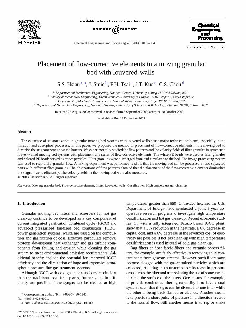
Fig. 2. The schematic drawing of the two-dimensional experimental mov-ing bed apparatus.
angle, and length). In this paper, the louver angleθ1 of 40◦ isused and the louver pitch (LP) is fixed as 350 mm. The lengthof the vertical part of the louver is 40 mm and the lengthof the inclined part is 200 mm. There are three louver-insertsections in the moving bed. Each flow-corrective element isformed by two steel plates with length 210 mm and internalangle (2θ2) of 60◦. The three flow-corrective elements wereconnected by a thin steal rod and placed in the vertical axisof moving bed.
The flow of granular solids is induced and controlled bya moving belt underneath the granular bed. Granules arefed into the vertical channel from a top hopper which has arectangular discharge slot of the same cross-section as thevertical channel. The front and the rear walls were cleanedcarefully before each experiment in order to reduce the wallfriction effect on the granular flows. Nevertheless, from theobservation of the inlet and the outlet granules positionsalong the path of 1 m (the total channel height), it was foundthat the granules close to the front wall were about 4 cmbehind the granules in the center of the moving bed. We canroughly say that the wall friction effect of the front and backwalls was limited within 4% of the granule path.
We have selected 6 mm diameter PE spheres with a den-sity of 964 kg/m3 as granular solids for the experiments.Packing of the spheres was characterized by the bulk densitymeasurements. Two bulk densities were measured: a pouredbulk density of 582 kg/m3 (porosity 0.396) and a tappedbulk density of 600.5 kg/m3 (porosity 0.377). Both densitieswere measured in a graduated glass cylinder. The mass flowrate measurements were made by continuous collection ofthe discharged granules in a tarred bucket. Weighing of fullbuckets was made with an electronic balance.
There were two parts of experimental tests. The first isthe observations on the flow patterns of filter granules inthe whole moving bed channel[7,24]. The moving bed wascirculated for two hours to reach the steady state condi-tions (meaning the steady bulk density distribution and flow
patterns). Then the space between the second pair of lou-vers under the top hopper was filled with colored granulesto observe the flow patterns of the moving bed. A SonyDCR-TRV 900 digital video camera recorder was used torecord the development of the flow of colored granulesuntil the colored granules left the granular bed completely.The camera was supported on a sturdy tripod and activatedseveral seconds before the flow of granules was started. Theimages can be transferred to a personal computer for futureanalyses.
The second part of experiments was the velocity mea-surements. For the velocity measurements, a volume of20% differentially colored granules uniformly dispersed inthe moving bed were used as tracers[7,8]. The Sony digitalvideo camera recorder was used to record the steady flowof the colored granules in one louver section for about onehour. It was believed that the moving bed had reached thesteady state conditions. The flow images could then be trans-ferred to and stored in a personal computer. By identifyingthe positions of every tracer particle in the consecutive im-ages, the granule displacements could be measured. Divid-ing the displacements by the time between two images, theindividual granule velocity could be found. The flow regionwas divided into approximate 500–600 subregions depend-ing on the louver configurations. The mean velocity in eachsubregion was calculated from averaging the whole tracerparticles’ velocities found within the subregion. Hence thevelocity field of the granular flow could be plotted. The ve-locity field results were taken by averaging flows for over 2 h.
4. Experimental results
4.1. Flow pattern observations and velocity fieldmeasurements
Kuo et al.[6] perform the flow pattern test using similarconfiguration but without the placement of flow-correctiveelements, and with smaller louver pitch. The test parametersare shown inTable 1. Fig. 3 shows the flow history of thecolored granules in 18 frames in the moving bed withoutflow-corrective elements[6], which is mostly used in indus-trial granular moving bed filters for hot gas clean-up. Thestagnant zones close to louver walls characterize the movingbed flow behavior.
Table 1Test conditions
Test parameter Test withflow-correctiveelements
Test withoutflow-corrective elements(Kuo et al. [6])
Louver length (mm) 200 200Louver spacing (mm) 350 200Number of louver pairs 3 4Mass flow rate (g/s) 3.52 3.51Refreshing rate (g/s) 1.58 0.4

S.S. Hsiau et al. / Chemical Engineering and Processing 43 (2004) 1037–1045 1041
Fig. 3. Flow patterns of filter granules in the moving bed without flow-corrective elements. Frames 1–11, time interval 2 min; frames 12–13, time interval4 min; frame 14, time 49 min; frame 15, time 89 min; frame 16, time 129 min; frame 17, time 169 min; frame 18, time 209 min[6].
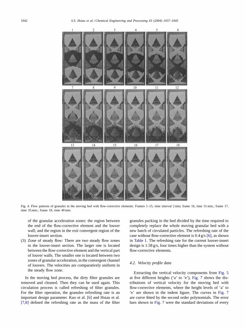
Fig. 4shows the flow history of the colored granules in 18frames in the moving bed with placement of flow-correctiveelements according to the calculation mentioned above.Frame 1 shows the beginning of the experiment. The timeinterval for frames 1–15 is 120 s. The frames followingframe 13 have progressively longer time intervals. FromFigs. 3 and 4, the times for the whole tracer particlesleaving the moving bed were 209 min for system withoutflow-corrective elements, while only 40 min in moving bedwith flow-corrective elements. The time for the whole tracerparticles leaving the bed is only for characterizing the stateof the “refreshment” of the moving bed. For measuring thetime of tracer particles leaving the moving bed, we watchedthe particles on the belt conveyer (Fig. 2) to make sure thatthere were no black particles in the outgoing particles fromthe moving bed.
Comparing the system configuration parameters shown inTable 1, the louver pitch in the current experiment is largerthan that in Kuo et al.’s[6] test. In the current system, thereare 45% more filter granules (deducting the free space un-der inserts) involved in the circulation, therefore the time
for exchange the old filter granules by new ones should belonger. Nevertheless, with the placement of flow-correctiveelements, the time for refreshing granules decreases signifi-cantly. It demonstrated that the placement of flow-correctiveelements could diminish the stagnant zones efficiently.
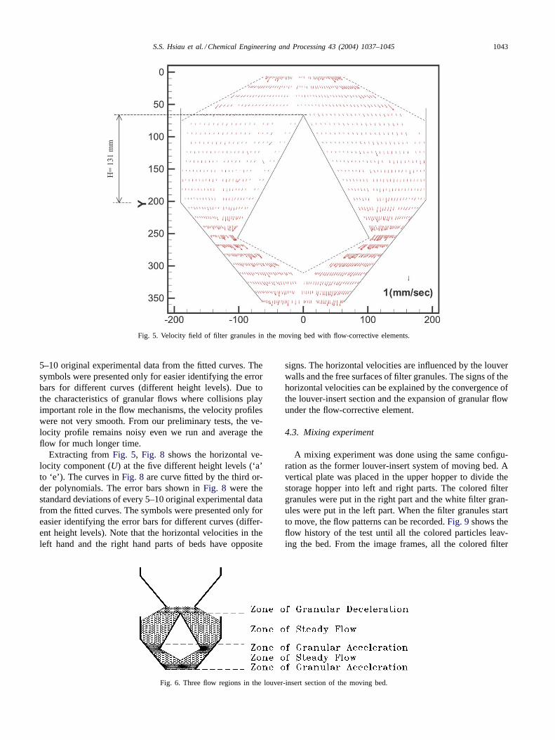
Fig. 5 shows the velocity field of the filter granules inthe louver-insert moving bed, the same system as it used inFig. 4. The symbols ofX andY represent the horizontal andvertical coordinates.
From Figs. 4 and 5, there existed three different flowregions in the louver-insert section, as shown inFig. 6,schematically:
(1) Zone of granular deceleration: This zone is located be-yond the exit of the upper louver-insert section. Sincethe granules move out from the louver-insert section andthe cross-sectional area of the flow expands with freesurfaces, the filter granules decrease their speed.
(2) Zone of granular acceleration: Opposite of the decelera-tion zone, the flow accelerates when the cross-sectionalarea of the flow decreases. There are two locations
1042 S.S. Hsiau et al. / Chemical Engineering and Processing 43 (2004) 1037–1045
Fig. 4. Flow patterns of granules in the moving bed with flow-corrective elements. Frames 1–15, time interval 2 min; frame 16, time 31 min.; frame 17,time 35 min.; frame 18, time 40 min.
of the granular acceleration zones: the region betweenthe end of the flow-corrective element and the louverwall; and the region in the exit convergent region of thelouver-insert section.
(3) Zone of steady flow: There are two steady flow zonesin the louver-insert section. The larger one is locatedbetween the flow-corrective element and the vertical partof louver walls. The smaller one is located between twozones of granular acceleration, in the convergent channelof louvers. The velocities are comparatively uniform inthe steady flow zone.
In the moving bed process, the dirty filter granules areremoved and cleaned. Then they can be used again. Thiscirculation process is called refreshing of filter granules.For the filter operation, the granules refreshing rate is animportant design parameter. Kuo et al.[6] and Hsiau et al.[7,8] defined the refreshing rate as the mass of the filter
granules packing in the bed divided by the time required tocompletely replace the whole moving granular bed with anew batch of circulated particles. The refreshing rate of thecase without flow-corrective element is 0.4 g/s[6], as shownin Table 1. The refreshing rate for the current louver-insertdesign is 1.58 g/s, four times higher than the system withoutflow-corrective elements.
4.2. Velocity profile data
Extracting the vertical velocity components fromFig. 5at five different heights (‘a’ to ‘e’),Fig. 7 shows the dis-tributions of vertical velocity for the moving bed withflow-corrective elements, where the height levels of ‘a’ to‘e’ are shown in the indent figure. The curves inFig. 7are curve fitted by the second order polynomials. The errorbars shown inFig. 7 were the standard deviations of every
S.S. Hsiau et al. / Chemical Engineering and Processing 43 (2004) 1037–1045 1043
Fig. 5. Velocity field of filter granules in the moving bed with flow-corrective elements.
5–10 original experimental data from the fitted curves. Thesymbols were presented only for easier identifying the errorbars for different curves (different height levels). Due tothe characteristics of granular flows where collisions playimportant role in the flow mechanisms, the velocity profileswere not very smooth. From our preliminary tests, the ve-locity profile remains noisy even we run and average theflow for much longer time.
Extracting fromFig. 5, Fig. 8 shows the horizontal ve-locity component (U) at the five different height levels (‘a’to ‘e’). The curves inFig. 8 are curve fitted by the third or-der polynomials. The error bars shown inFig. 8 were thestandard deviations of every 5–10 original experimental datafrom the fitted curves. The symbols were presented only foreasier identifying the error bars for different curves (differ-ent height levels). Note that the horizontal velocities in theleft hand and the right hand parts of beds have opposite
Fig. 6. Three flow regions in the louver-insert section of the moving bed.
signs. The horizontal velocities are influenced by the louverwalls and the free surfaces of filter granules. The signs of thehorizontal velocities can be explained by the convergence ofthe louver-insert section and the expansion of granular flowunder the flow-corrective element.
4.3. Mixing experiment
A mixing experiment was done using the same configu-ration as the former louver-insert system of moving bed. Avertical plate was placed in the upper hopper to divide thestorage hopper into left and right parts. The colored filtergranules were put in the right part and the white filter gran-ules were put in the left part. When the filter granules startto move, the flow patterns can be recorded.Fig. 9shows theflow history of the test until all the colored particles leav-ing the bed. From the image frames, all the colored filter

1044 S.S. Hsiau et al. / Chemical Engineering and Processing 43 (2004) 1037–1045
Fig. 7. The vertical velocity distributions (second-order curve fitting) atfive vertical height levels for the test in the moving bed with flow-corrective elements. The error bars shown in the figure were the standarddeviations of every 5–10 original experimental data from the fitted curves.
Fig. 9. Flow patterns of different colored granules mixing in the moving bed with flow-corrective elements. Frames 1–8, time interval 6 min; frame 9,time 70 min.; frame 10, time 84 min.; frames 11–17, time interval 6 min., frame 18, time 138 min.
Fig. 8. The horizontal velocity distributions (third-order curve fitting)at five vertical height levels for the test in the moving bed with flow-corrective elements. The error bars shown in the figures were the standarddeviations of every 5–10 original experimental data from the fitted curves.

S.S. Hsiau et al. / Chemical Engineering and Processing 43 (2004) 1037–1045 1045
granules remain in the right part of the moving bed duringthe whole process. It indicates that there is no mixing be-tween the left and the right channel. Therefore, the currentdesign apparatus can be run with two different processes ortwo different filter media, in the left and the right parts ofmoving bed independently.
5. Conclusions
The current study performed the test in a granular mov-ing bed with 40◦ louvered-walls and with a series offlow-corrective elements placed in the bed. Comparing withour earlier results without placement of flow-corrective ele-ments, the quasi-stagnant zones are effectively diminishedwith the current new design. The velocity fields and profileswere also analyzed in this paper.
The mixing experiment performed in this paper alsoshows the capability of the moving bed with louvered-wallsand with flow-corrective elements to run two different pro-cesses or two different filter media, in two sides of themoving bed simultaneously.
Acknowledgements
The authors gratefully acknowledge the financial supportfrom the National Science Council of the ROC for thiswork through project NSC 90-2211-E-008-034 and NSC90-2211-E-008-035. J.S. was financially supported in partsby grant no. GACR 101/01/0955 of the Research Project ofGrant Agency of the Czech Republic.
Appendix A
NomenclatureLP louver pitch, (mm)L length of the inclined part of the louvers, (mm)l length of the flow-corrective element, (mm)U horizontal velocity, (mm/s)V vertical velocity, (mm/s)w channel width, (mm)X horizontal co-ordinate, (mm)Y vertical co-ordinate, (mm)
Greek lettersθ1 louver inclined angle (◦)θ2 a half of the internal angle of
flow-corrective element (◦)
References
[1] A.M. Robin, D.Y. Jung, J.S. Kassman, T.F. Leininger, J. K. Wolfen-barger, P.P. Yang, Integration and testing of hot desulfurization andentrained flow gasification for power generation systems, R. A. John-son, S.C. Jain (Eds.), in: Proceedings of the 12th Annual Gasifica-
tion and Gas Clean-up Systems Contractors Review Meeting 1 1992pp. 95–104.
[2] J.R. Longanbach, Preparing advanced coal-based power systemsfor the 21st century at the power systems development facility inWilsonville, Alabama, in: Proceedings of the 23rd International Tech-nical Conference on Coal Utilization and Fuel Systems, Clearwater,Florida, USA., 1998, pp. 69–78.
[3] R.G. Reese, The application of a dry scrubber to exhaust gas clean-up,Tappi (J. Tech. Assoc. Pulp and Pap. Ind.) 60 (1977) 109–111.
[4] K. Ishikawa, N. Kawamata, K. Kamei, Development of a simulta-neous sulfer and dust removal process for IGCC Power GenerationSystem, in: R. Clift and J.P.K. Seville (Eds.), Gas Cleaning at HighTemperature, Blackie Academic and Professionals, London, 1993,pp.419–435.
[5] Avco Co., Evaluation of granular bed devices. Final Report, ContractNo. PH-86-67-51, Phase III, AVATD-0107-67-RR, U.S. Departmentof Commerce, Publication PB 185561, June 1969. Submitted by Ad-vanced Chemical Process Section, Avco Applied Technology Divi-son, Lowell, Massachusetts 01851, USA. 1969, pp. 8–9, 48, 67–68.
[6] J.T. Kuo, J. Smid, S.S. Hsiau, C.Y. Wang, C.S. Chou, Stagnant zonesin granular moving bed filters for flue gas clean-up, Filtr. Sep. 35(1998) 529–534.
[7] S.S. Hsiau, J. Smid, C.Y. Wang, J.T. Kuo, C.S. Chou, Velocityprofiles of granules in moving bed filters, Chem. Eng. Sci. 54 (1999)293–301.
[8] S.S. Hsiau, J. Smid, F.H. Tsai, J.T. Kuo, C.S. Chou, Velocities inmoving bed filters, Powder Technol. 114 (2001) 205–212.
[9] W. Thielen, G. Thomas, Vorrichtung zur Aufnahme von voneinem Gasstrom durchströmten rieselfähigen Schüttgut, Ger. Patent3817685, 1988.
[10] W. Lindner, Leitblechanordnung für Schüttschichtfilter- und/oderReaktoren, Ger. Patent 4030896, 1990.
[11] N. Priefer, F. Wittenmeier, K. Weckerle, Reaktor zum Reinigen vonIndustrieabgasen, Ger. Patent 3830618, 1988.
[12] Lufttechnik Bayreuth Rüskamp GmbH, Bayreuth, Kern-forschungszentrum Karlsruhe GmbH, Karlsruhe, Einrichtung zurHalterung und Führung von Schichten, Ger. Patent 3526426, 1985.
[13] K. Furuyama, Y. Ito, Reactor of moving bed type, U.S. Patent4,670,226, see also European Patent Application EP 0 198 133, 1985.
[14] G. Nöth, Verfahren und Vorrichtung zum Entfernen von Schadstoffenaus Rauch- und Abgasen mit integriertem Wärmetauschersystem,Ger. Patent 4002462, 1990.
[15] V.I. Chumarnyi, D.A. Sushchinskii, E.V. Reshetova, V. P. Ilchenko,A.A. Vorfolomeev, A.N. Rekhtman, Dvukhsloinyi zernistyi radialnyifiltr s podvizhnoi nasadkoi, S.U. Patent 904746, 1980.
[16] Chemiebau Dr. A. Zieren, GmbH and Co. KG, Adsorption apparatus,U.K. Patent Specification 1,318,622, 1970.
[17] F. Johswich, W. Schindelbeck, Adsorption method and apparatus fortreating polluted gas streams, U.S. Patent 3,708,981, 1970.
[18] J.R. Johanson, The use of flow-corrective inserts in bins, Trans.ASME Ser. B J. Eng. Ind. 88 (1966) 224–230.
[19] J.R. Johanson, The placement of insert to correct flow problems,Powder Technol. 1 (1967/68) 328–333.
[20] J.R. Johanson, W.K. Kleysteuber, Flow-corrective inserts in bins,Chem. Eng. Progressing 62 (1966) 79–83.
[21] J. Strusch, J. Schwedes, B. Hardow, M. Kaldenhoff, Insert loads andwall stress distributions in silos with inserts, in: proceedings of thePreprints third European Symponium Storage and Flow of ParticulateSolids, Nuremberg, 1995, pp. 163-172.
[22] A.W. Jenike, Gravity flow of bulk solids, Bulletin No. 108, Engng.Exp. Station, Univ. of Utah, Salt Lake City, 1961.
[23] Jenike Shear Tester (1998), Model FT-5STEH, Jenike Shear Testerand Consolidating Bench Operating Instructions, (Revised) Jenikeand Johanson, Inc., Westford, MA, USA, January 1998.
[24] S.S. Hsiau, J. Smid, H.H. Tsai, J.T. Kuo, C.S. Chou, Flow patternsand velocity fields of granules in Dorfan Impingo filters for gasclean-up, Chem. Eng. Sci. 55 (2000) 4481–4494.


![Rheem Commercial Classic Series Package Heat Pump · Outdoor Sound Rating (dB)3 76 76 76 Outdoor Coil—Fin Type Louvered Louvered Louvered ... [7.03-14.07 kW] See Page 10 for Notes](https://img.pdfslide.us/doc/110x75/5f72b476a8e4734f724f3d92/rheem-commercial-classic-series-package-heat-pump-outdoor-sound-rating-db3-76.jpg)