Embed Size (px)
DESCRIPTION
pole in road
Citation preview
Policy Statement 1
Policy Statement
Subject Placement of Distribution Poles Along Roads With Speed Limits Not Exceeding 70km/h
Approved by Robert Rogerson Distribution Standards and Policy Manager
Signature & Date
Authorised by Mark Wilshusen Manager Standards, Policy & Data Quality
Signature & Date
Issue Date 14 August 2006 Issue Initial
Objective To position frangible poles, used for streetlights, a safe distance from the road to minimise the likelihood of them being accidentally hit by vehicles.
Context It is not uncommon for vehicles to leave the carriageway and collide with solid structures, including frangible poles. Even though frangible poles are less likely than rigid poles to cause serious injury or death, they still have to be positioned at a certain distance from the road to minimise this hazard.
References and Supporting Documentation http://www.mainroads.wa.gov.au/internet/standards/rtems/roadside/services/guiderelocprotserv.asp -
Main Roads website – Guide to the Relocation or Protection of Services.
http://www.mainroads.wa.gov.au/internet/standards/rtems/roadside/barriers.asp - Main Roads website – Guide to the Design of Road Safety Barriers.
http://www.mainroads.wa.gov.au/NR/rdonlyres/0B774C88-78A5-44F6-850B-F012E9A1F265/0/utility.pdf - Main Roads website – Utility Providers Code of Practice.
AS/NZS 3845:1999, Road safety barrier.
Section 17 of the Rural Road Design, published by Austroads.
Section 14 of the Urban Road Design, published by Austroads.
Appendix B, AS1158.1.3-1997, Guidelines for the use and placement of rigid and frangible road lighting poles.
Policy Statement 2
Introduction Main Roads WA defines its requirements for the placement of poles in the Guide to the Relocation or Protection of Services, Section 4.3, as follows:
Where practical:
Services should be placed on the alignment given in Appendix B of the Utility Providers Code of Practice.
Above-ground services should be placed outside the Clear Zone, as detailed in the Guide to the Design of Road Safety Barriers, so as not to pose a hazard to motorists.
The Guide to the Design of Road Safety Barriers Section 2, states that the Clear Zone should be determined in accordance with Austroads’ Urban Roads Design – Guide to the Geometric Design of Major Urban Roads and Rural Road Design – Guide to the Geometric Design of Rural Roads. The Clear Zone is defined in AS/NZS 3845:1999, Section 1.4.9, as “the horizontal width of space available for the safe use of an errant vehicle which consists of the verge area and is measured from the nearside edge of the left-hand traffic lane. In the case of a divided road, it is also measured from the offside edge of the right-hand traffic lane to the edge of the pavement for opposing traffic”.
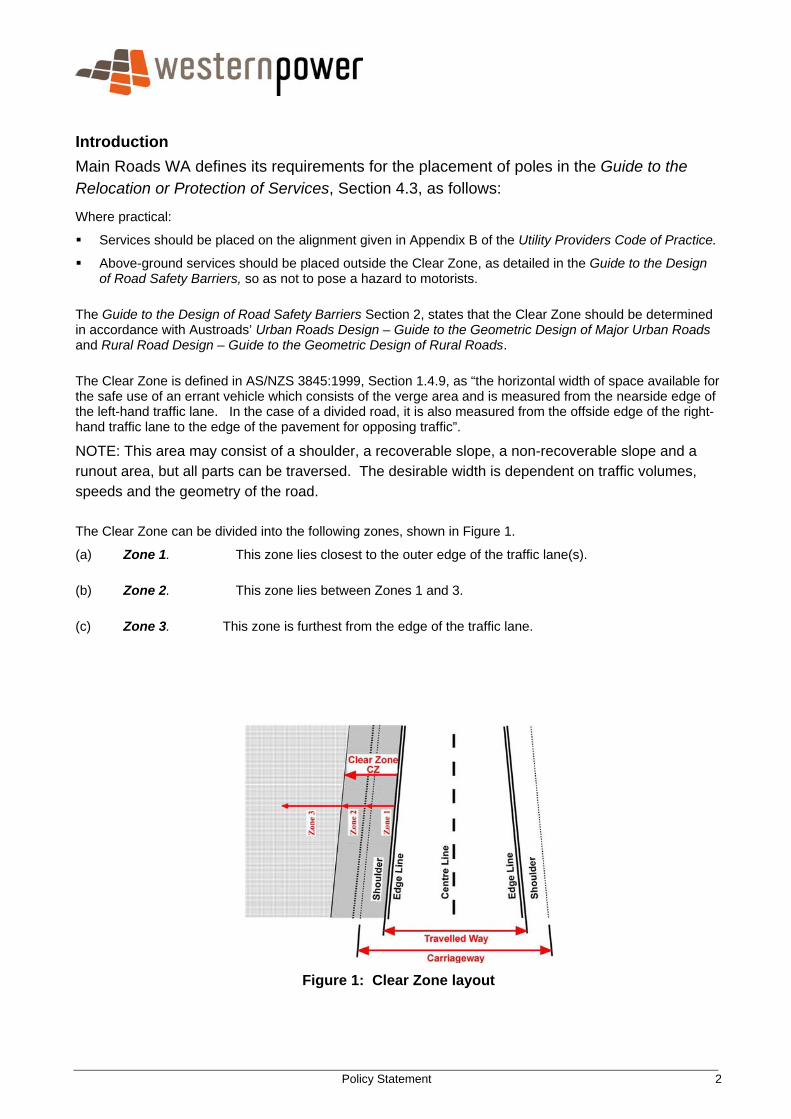
NOTE: This area may consist of a shoulder, a recoverable slope, a non-recoverable slope and a runout area, but all parts can be traversed. The desirable width is dependent on traffic volumes, speeds and the geometry of the road. The Clear Zone can be divided into the following zones, shown in Figure 1.
(a) Zone 1. This zone lies closest to the outer edge of the traffic lane(s). (b) Zone 2. This zone lies between Zones 1 and 3. (c) Zone 3. This zone is furthest from the edge of the traffic lane.
Figure 1: Clear Zone layout
Policy Statement 3
According to the Austroads guides, the minimum width of the Clear Zone is 3m. However, in urban low-speed areas, where it can be difficult to achieve a 3m width, the Urban Roads Design Guide states that a reduced Clear Zone of 1m may be acceptable. This applies only to established residential areas. In the case of greenfield sites, a Clear Zone of 3-4m should always be considered.
The Austroads guides do not provide any more details on this reduction. However, the Australian Standard AS1158.1.3–1997, Appendix B - Guidelines for the Use and Placement of Rigid and Frangible Road Lighting Poles - also deals with this subject. It does not make any direct reference to the Austroads guides, but is consistent with them and, consequently, is used as a basis for this policy. Policy Statement Poles (both frangible and rigid) may not be located within Zone 1. Frangible poles are acceptable for use within Zone 2 except for slip-base poles, which should not be used in areas with high pedestrian activity.
Rigid poles are not recommended but are acceptable within Zone 2. If rigid poles are installed then they should be placed to achieve the maximum distance from traffic lanes. All poles can be installed in Zone 3, except for slip-base poles, which should not be used in areas with high pedestrian activity. Policy Details Slip-base frangible poles are used by Main Roads. Western Power installs only impact-absorbing frangible poles. The widths of Zones 1 and 2 vary depending on road configuration. For example, straight sections are different from intersections, islands, roundabouts and bends. Zone widths also depend on the type of embankment and whether there are safety barriers and/or other obstructions. When calculating the width of Zones 1 and 2, remember:
The widths of Zones 1 and 2 should add up to at least 3m - that is, the Clear Zone.
Zone 1 starts at the inside edge of the kerb or at the edge of the traffic lane (for roads without kerbs).
If there is a kerb, the minimum width of Zone 1 is 0.7m.
If there is no kerb, the minimum width of Zone 1 is 1m.
In the vicinity of intersections, islands, roundabouts and bends the minimum width of Zone 1 is 1m.
The restrictions associated with placing poles in Zone 1 or Zone 2 do not apply when existing poles are being replaced with new poles in the same vicinity and this replacement does not increase the existing risk level to road users. The new poles may be taller but their diameter should be similar to the old poles. Along straight sections of a road, the widths of Zones 1 and 2 vary depending on whether there is a kerb, shoulder or parking lane next to the traffic lane. However, Zone 1 should be a minimum of 0.7m wide. There are three possible combinations of these factors:
Case 1 Roadway with a kerb but without a shoulder or parking lane
Policy Statement 4
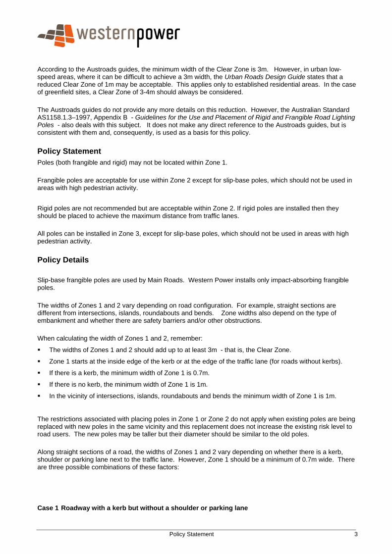
Zone 1 is 0.7m wide and Zone 2 is 2.3m wide, as shown in Figure 2. The Clear Zone extends 3m from the edge of the roadway.
Figure 2: Road with a kerb, but without shoulder or parking lane. Case 2 Roadway with a kerb and shoulder or parking line, in a straight road section
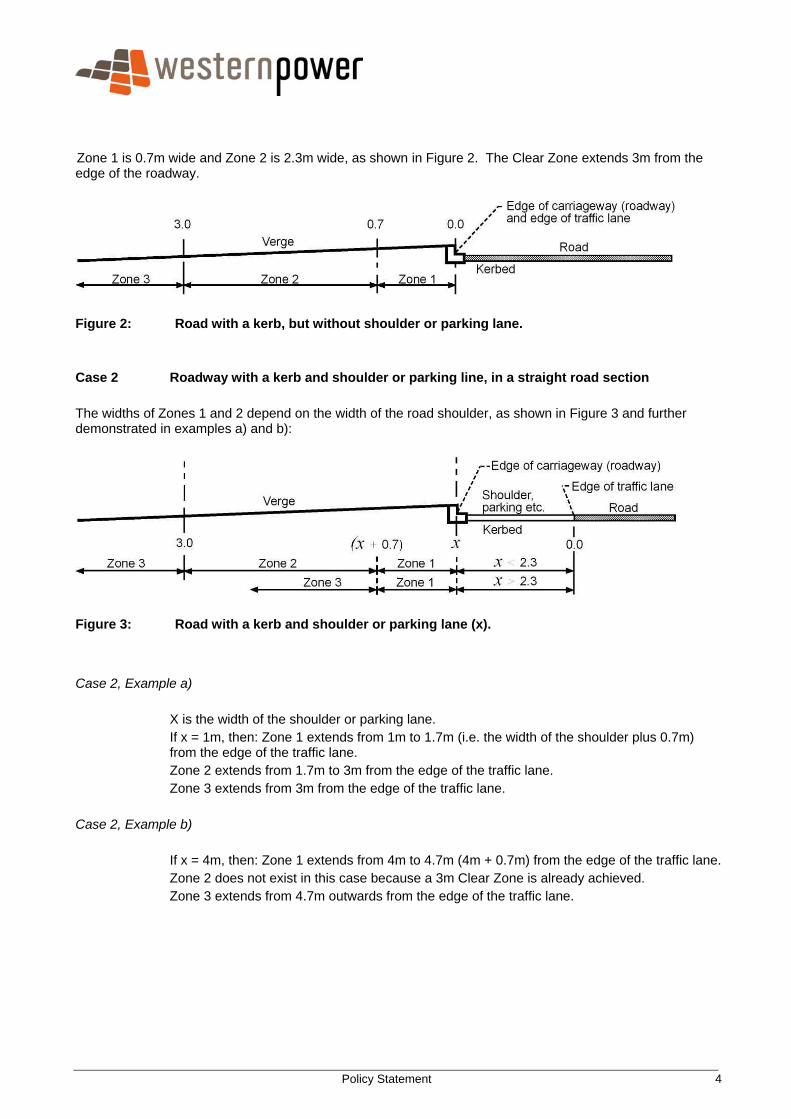
The widths of Zones 1 and 2 depend on the width of the road shoulder, as shown in Figure 3 and further demonstrated in examples a) and b):
Figure 3: Road with a kerb and shoulder or parking lane (x).
Case 2, Example a)
X is the width of the shoulder or parking lane. If x = 1m, then: Zone 1 extends from 1m to 1.7m (i.e. the width of the shoulder plus 0.7m) from the edge of the traffic lane. Zone 2 extends from 1.7m to 3m from the edge of the traffic lane. Zone 3 extends from 3m from the edge of the traffic lane.
Case 2, Example b)
If x = 4m, then: Zone 1 extends from 4m to 4.7m (4m + 0.7m) from the edge of the traffic lane. Zone 2 does not exist in this case because a 3m Clear Zone is already achieved. Zone 3 extends from 4.7m outwards from the edge of the traffic lane.
Policy Statement 5
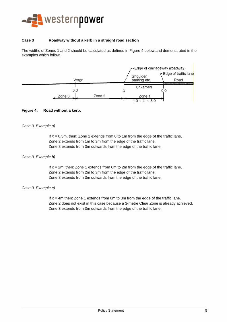
Case 3 Roadway without a kerb in a straight road section
The widths of Zones 1 and 2 should be calculated as defined in Figure 4 below and demonstrated in the examples which follow.
Figure 4: Road without a kerb.
Case 3, Example a) If x = 0.5m, then: Zone 1 extends from 0 to 1m from the edge of the traffic lane. Zone 2 extends from 1m to 3m from the edge of the traffic lane. Zone 3 extends from 3m outwards from the edge of the traffic lane.
Case 3, Example b)
If x = 2m, then: Zone 1 extends from 0m to 2m from the edge of the traffic lane. Zone 2 extends from 2m to 3m from the edge of the traffic lane. Zone 3 extends from 3m outwards from the edge of the traffic lane.
Case 3, Example c)
If x = 4m then: Zone 1 extends from 0m to 3m from the edge of the traffic lane. Zone 2 does not exist in this case because a 3-metre Clear Zone is already achieved. Zone 3 extends from 3m outwards from the edge of the traffic lane.
Policy Statement 6
Intersections, Islands, Roundabouts and Bends
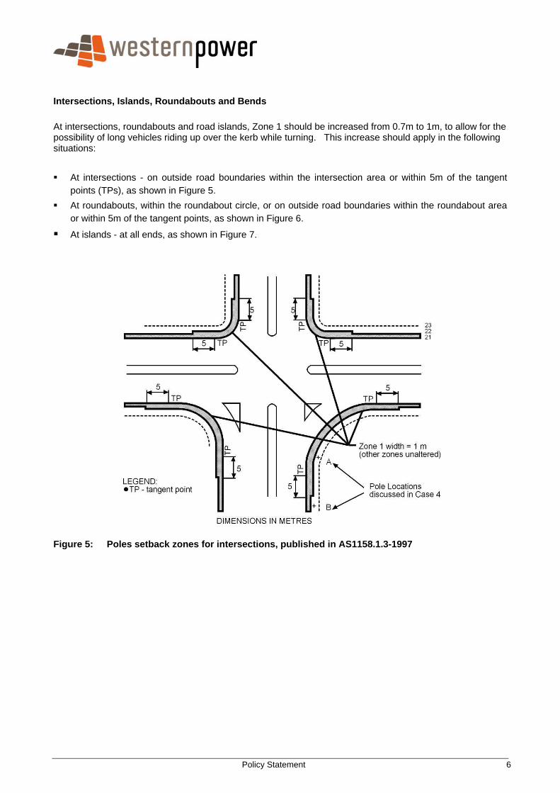
At intersections, roundabouts and road islands, Zone 1 should be increased from 0.7m to 1m, to allow for the possibility of long vehicles riding up over the kerb while turning. This increase should apply in the following situations:
At intersections - on outside road boundaries within the intersection area or within 5m of the tangent points (TPs), as shown in Figure 5.
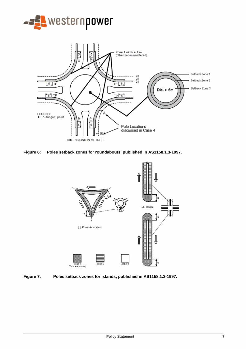
At roundabouts, within the roundabout circle, or on outside road boundaries within the roundabout area or within 5m of the tangent points, as shown in Figure 6.
At islands - at all ends, as shown in Figure 7.
Figure 5: Poles setback zones for intersections, published in AS1158.1.3-1997
Policy Statement 7
Figure 6: Poles setback zones for roundabouts, published in AS1158.1.3-1997.
Figure 7: Poles setback zones for islands, published in AS1158.1.3-1997.
Policy Statement 8
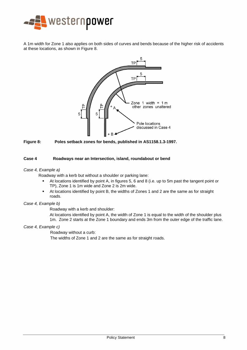
A 1m width for Zone 1 also applies on both sides of curves and bends because of the higher risk of accidents at these locations, as shown in Figure 8.
Figure 8: Poles setback zones for bends, published in AS1158.1.3-1997. Case 4 Roadways near an Intersection, island, roundabout or bend Case 4, Example a) Roadway with a kerb but without a shoulder or parking lane:
At locations identified by point A, in figures 5, 6 and 8 (i.e. up to 5m past the tangent point or TP), Zone 1 is 1m wide and Zone 2 is 2m wide.
At locations identified by point B, the widths of Zones 1 and 2 are the same as for straight roads.
Case 4, Example b) Roadway with a kerb and shoulder: At locations identified by point A, the width of Zone 1 is equal to the width of the shoulder plus 1m. Zone 2 starts at the Zone 1 boundary and ends 3m from the outer edge of the traffic lane.
Case 4, Example c) Roadway without a curb: The widths of Zone 1 and 2 are the same as for straight roads.
Policy Statement 9
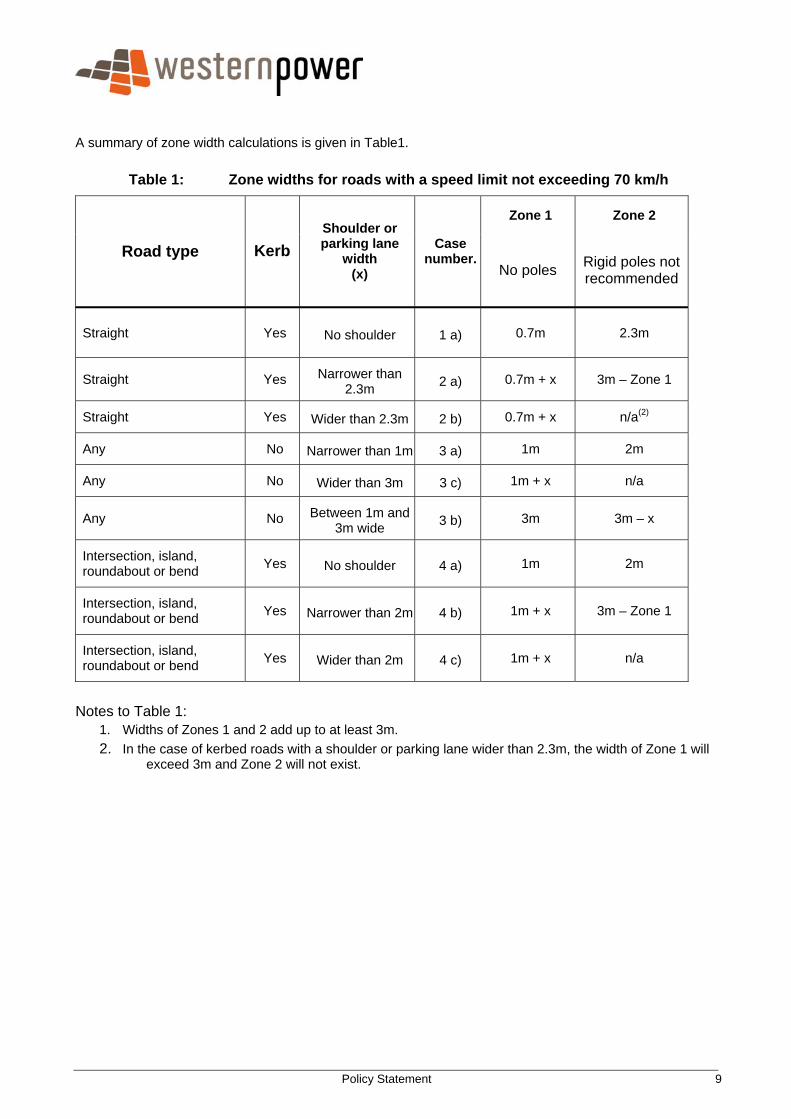
A summary of zone width calculations is given in Table1.
Table 1: Zone widths for roads with a speed limit not exceeding 70 km/h
Zone 1 Zone 2
Road type Kerb Shoulder or parking lane
width (x)
Case number.
No poles Rigid poles not recommended
Straight Yes No shoulder 1 a) 0.7m 2.3m
Straight Yes Narrower than 2.3m 2 a) 0.7m + x 3m – Zone 1
Straight Yes Wider than 2.3m 2 b) 0.7m + x n/a(2)
Any No Narrower than 1m 3 a) 1m 2m
Any No Wider than 3m 3 c) 1m + x n/a
Any No Between 1m and 3m wide 3 b) 3m 3m – x
Intersection, island, roundabout or bend Yes No shoulder 4 a) 1m 2m
Intersection, island, roundabout or bend Yes Narrower than 2m 4 b) 1m + x 3m – Zone 1
Intersection, island, roundabout or bend Yes Wider than 2m 4 c) 1m + x n/a
Notes to Table 1:
1. Widths of Zones 1 and 2 add up to at least 3m. 2. In the case of kerbed roads with a shoulder or parking lane wider than 2.3m, the width of Zone 1 will
exceed 3m and Zone 2 will not exist.
Policy Statement 10
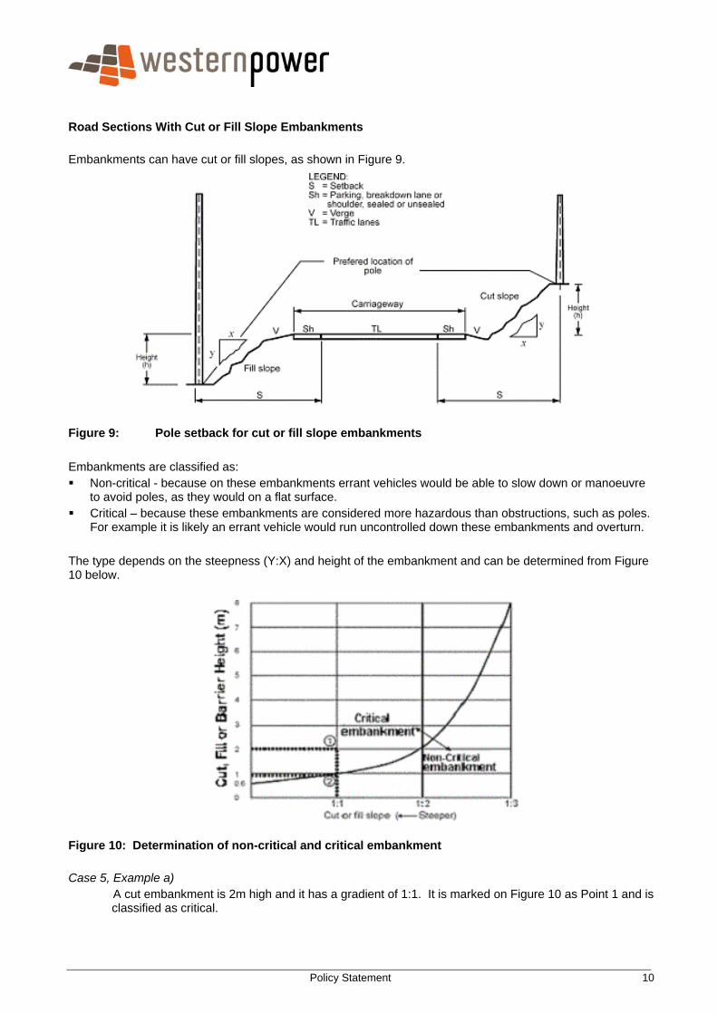
Road Sections With Cut or Fill Slope Embankments
Embankments can have cut or fill slopes, as shown in Figure 9.
Figure 9: Pole setback for cut or fill slope embankments Embankments are classified as: Non-critical - because on these embankments errant vehicles would be able to slow down or manoeuvre
to avoid poles, as they would on a flat surface. Critical – because these embankments are considered more hazardous than obstructions, such as poles.
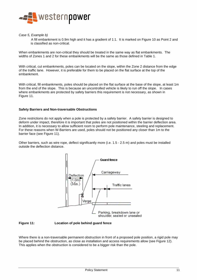
For example it is likely an errant vehicle would run uncontrolled down these embankments and overturn. The type depends on the steepness (Y:X) and height of the embankment and can be determined from Figure 10 below.
Figure 10: Determination of non-critical and critical embankment Case 5, Example a)
A cut embankment is 2m high and it has a gradient of 1:1. It is marked on Figure 10 as Point 1 and is classified as critical.
Policy Statement 11
Case 5, Example b) A fill embankment is 0.9m high and it has a gradient of 1:1. It is marked on Figure 10 as Point 2 and is classified as non-critical.
When embankments are non-critical they should be treated in the same way as flat embankments. The widths of Zones 1 and 2 for these embankments will be the same as those defined in Table 1.
With critical, cut embankments, poles can be located on the slope, within the Zone 2 distance from the edge of the traffic lane. However, it is preferable for them to be placed on the flat surface at the top of the embankment.
With critical, fill embankments, poles should be placed on the flat surface at the base of the slope, at least 1m from the end of the slope. This is because an uncontrolled vehicle is likely to run off the slope. In cases where embankments are protected by safety barriers this requirement is not necessary, as shown in Figure 11. Safety Barriers and Non-traversable Obstructions Zone restrictions do not apply when a pole is protected by a safety barrier. A safety barrier is designed to deform under impact, therefore it is important that poles are not positioned within the barrier deflection area. In addition, it is necessary to allow sufficient room to perform pole maintenance, steeling and replacement. For these reasons when W-Barriers are used, poles should not be positioned any closer than 1m to the barrier face (see Figure 11). Other barriers, such as wire rope, deflect significantly more (i.e. 1.5 - 2.5 m) and poles must be installed outside the deflection distance.
Figure 11: Location of pole behind guard fence
Where there is a non-traversable permanent obstruction in front of a proposed pole position, a rigid pole may be placed behind the obstruction, as close as installation and access requirements allow (see Figure 12). This applies when the obstruction is considered to be a bigger risk than the pole.

Policy Statement 12
Figure 12: Non-traversable permanent obstruction in front of pole.