Embed Size (px)
Citation preview
PL700Original instructions
Important!
It is essential that you read the instructions in this manual before assembling, operating and maintaining the product.
Subject to technical modifications.
11
111111Technical Data, Safety Instructions, Specified Conditions of Use,Declaration of Conformity, Mains connection, Maintenance, Symbols
Please read and savethese instructions! English
22
10
20
18
10
20
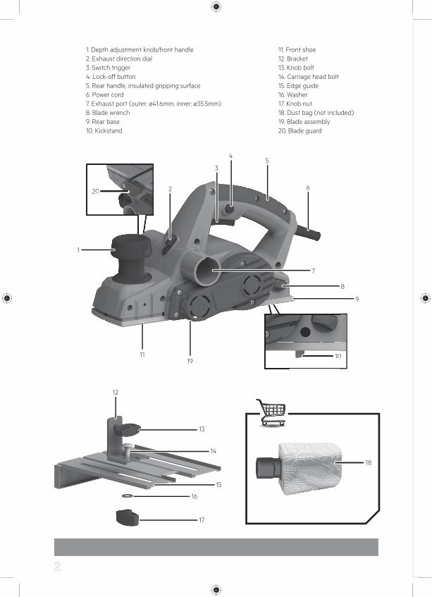
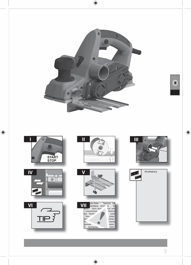
1. Depth adjustment knob/front handle2. Exhaust direction dial3. Switch trigger4. Lock-off button5. Rear handle, insulated gripping surface6. Power cord7. Exhaust port (outer: ø41.6mm, inner: ø35.5mm)8. Blade wrench9. Rear base10. Kickstand
11. Front shoe12. Bracket13. Knob bolt14. Carriage head bolt15. Edge guide16. Washer17. Knob nut18. Dust bag (not included)19. Blade assembly20. Blade guard
1
12
2
4
35
8
9
13
14
15
16
17
1119
7
6
33
I II
V
VIIVI
IV Accessory
III
44
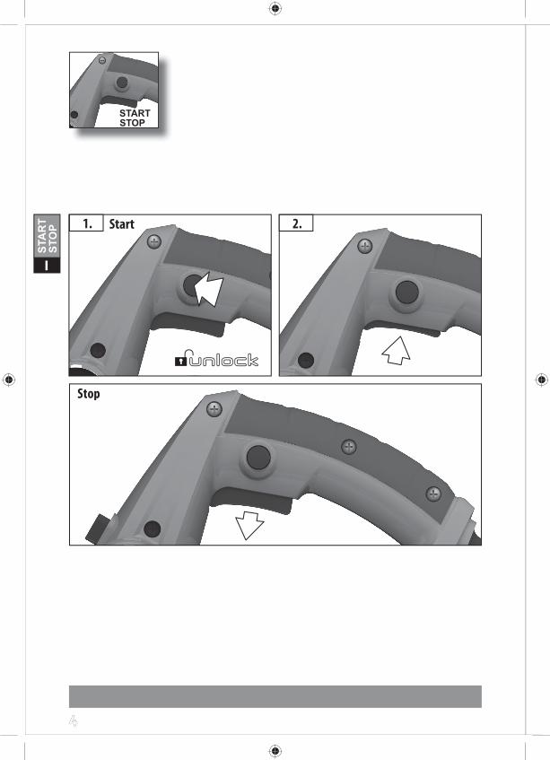
I
Start1. 2.
StopStop
55
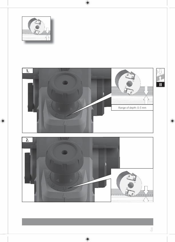
II
1.
2.22.2.
Range of depth: 0-3 mm
66
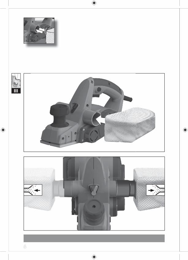
III
77
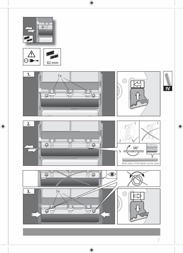
IV
1.
2. 1
2
3.
1x180°
3 x
3 x
1
82 mm
Both sides of the blade can be used
88
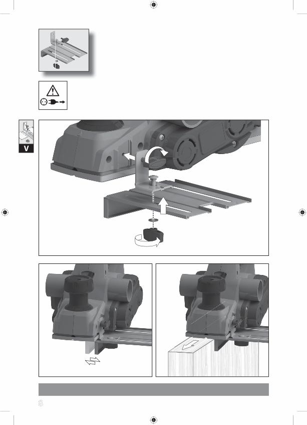
V
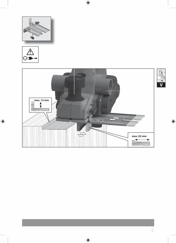
99
max. 82 mm
V
max. 12 mm
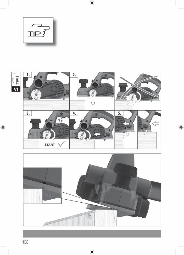
101010
3. 4. 5.
1. 2.
VI
111111
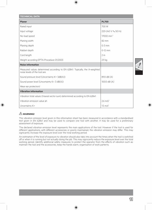
TECHNICAL DATA
Planer PL700
Rated input 700 W
Input voltage 220-240 V 50 Hz
No-load speed 17000 min-1
Planing width 82 mm
Planing depth 0-3 mm
Rabbet depth 0-12 mm
Cord length 2 m
Weight according EPTA-Procedure 01/2003 2.9 kg
Noise information
Measured values determined according to EN 62841. Typically, the A-weighted noise levels of the tool are:
Sound pressure level (Uncertainty K= 3dB(A)) 89.0 dB (A)
Sound power level (Uncertainty K= 3 dB(A)) 100.0 dB (A)
Wear ear protectors!
Vibration information
Vibration total values (triaxial vector sum) determined according to EN 62841
Vibration emission value ah 2.6 m/s2
Uncertainty K= 1.5 m/s2
WARNING!
The vibration emission level given in this information sheet has been measured in accordance with a standardised test given in EN 62841 and may be used to compare one tool with another. It may be used for a preliminary assessment of exposure.
The declared vibration emission level represents the main applications of the tool. However if the tool is used for diff erent applications, with diff erent accessories or poorly maintained, the vibration emission may diff er. This may signicantly increase the exposure level over the total working period.
An estimation of the level of exposure to vibration should also take into account the times when the tool is switched off or when it is running but not actually doing the job. This may signicantly reduce the exposure level over the total working period. Identify additional safety measures to protect the operator from the eff ects of vibration such as: maintain the tool and the accessories, keep the hands warm, organisation of work patterns.
121212
WARNING!
Read all safety warnings and all instructions. Failure to follow the warnings and instructions may result in electric shock, fire and/or serious injury. Save all warnings and instructions for future reference.
PLANER SAFETY WARNINGSWait for the cutter to stop before setting the tool down. An exposed rotating cutter may engage the surface leading to possible loss of control and serious Injury.
Hold the power tool by insulated gripping surfaces only, because the cutter may contact its own cord. Cutting a “live” wire may make exposed metal parts of the power tool live and could give the operator an electric shock.
Use clamps or another practical way to secure and support the workpiece to a stable platform. Holding the work by your hand or against the body leaves it unstable and may lead to loss of control.
ADDITIONAL SAFETY AND WORKING INSTRUCTIONS
Wear ear protectors. Exposure to noise can cause hearing loss. Always use the protective shields on the machine.
Use protective equipment. Always wear safety glasses when working with the machine. The use of protective clothing is recommended, such as dust mask, protective gloves, sturdy non-slip footwear, helmet and ear defenders.
The dust produced when using this tool may be harmful to health. Do not inhale the dust. Use a dust absorption system and wear a suitable dust protection mask. Remove deposited dust thoroughly, e.g. with a vacuum cleaner.
Do not use compressed air to blow dust or debris. This practice is dangerous and can cause dirt and grit to be blasted off and injure someone’s eyes.
Chips and splinters must not be removed while the product is running.
Do not drill the housing, as the protective insulation would be rendered ineff ective. Use adhesive labels.
Only plane with sharp blades and avoid metal (nails, screws).
Always disconnect the plug from the socket before carrying out any work on the product.
SPECIFIED CONDITIONS OF USEThe planer can plane surfaces and rabbets, and bevel and chamfer edges.
Do not use this product in any other way as stated for normal use.
RESIDUAL RISKSEven when the product is used as prescribed, it is still impossible to completely eliminate certain residual risk factors. The following hazards may arise and the operator should pay special attention to avoid the following:
■ Injury caused by dust and debris
● Considerable dust and debris will be produced, always connect dust bag to the product.
● Wear eye protection at all times.
● Wear respiratory protection masks containing filters appropriate to the materials being worked. Ensure adequate workplace ventilation.
● Do not eat, drink or smoke in the work area.
■ Injury caused by noise and vibration
● Wear ear protection during operation. Do not operate the product for long periods of time. See “Risk reduction”.
■ Injury from contact with the cutting blades
● The accessories are sharp and will become hot during use.
● Wear gloves when changing blades.
● Keep hands away from the cutting area at all times.
RISK REDUCTIONIt has been reported that vibrations from handheld tools may contribute to a condition called Raynaud’s Syndrome in certain individuals. Symptoms may include tingling, numbness and blanching of the fingers, usually apparent upon exposure to cold. Hereditary factors, exposure to cold and dampness, diet, smoking and work practices are all thought to contribute to the development of these symptoms. There are measures that can be taken by the operator to possibly reduce the eff ects of vibration:
Keep your body warm in cold weather. When operating the unit wear gloves to keep the hands and wrists warm. It is reported that cold weather is a major factor contributing to Raynaud’s Syndrome.
After each period of operation, exercise to increase blood circulation.
Take frequent work breaks. Limit the amount of exposure per day.
If you experience any of the symptoms of this condition, immediately discontinue use and see your doctor about these symptoms.
WARNING Injuries may be caused or aggravated by prolonged use of a tool. When using any tool for prolonged periods, ensure you take regular breaks.
131313
WORKING INSTRUCTIONSNever reach into the danger area of the plane when it is running.
Place the front side of the product on to the workpiece and switch on, before the planer blade touches the workpiece and then guide evenly over the workpiece.
The v-shape notch in the front of the supporting plate ensures safe chamfering of edges.
MAINS CONNECTIONConnect only to a single-phase AC current supply and only to the mains voltage specified on the rating plate. Must only be used from sockets with earth wire.
Appliances used at many diff erent locations including wet room and open air must be connected via a residual current device (FI, RCD, PRO) of 30mA or less.
Keep mains lead clear from working range of the machine. Always lead the cable away behind you.
MAINTENANCEThe ventilation slots of the machine must be kept clear at all times.
If the power supply cord is damaged, it must be replaced only by the manufacturer or by an authorised service centre to avoid a safety hazard. Contact authorised service centre.
Important note! If the carbon brushes are worn, In addition to exchanging the brushes the tool should be sent to after-sales service. This will ensure long service life and top performance.
Use only AEG accessories and spare parts. Should components need to be replaced which have not been described, please contact one of our AEG service agents (see our list of guarantee/service addresses).
If needed, an exploded view of the tool can be ordered. Please state the machine type printed as well as the six-digit No. on the label and order the drawing at your local service agents or directly at:
Techtronic Industries Australia Pty Ltd
PO Box 1065Mount Waverley VIC 3149Tel. no. 1300 234 797Australia
Techtronic Industries N.Z. Limited
PO Box 12-806Penrose AUCKLAND 1642Tel. no. 0800 234 797New Zealand
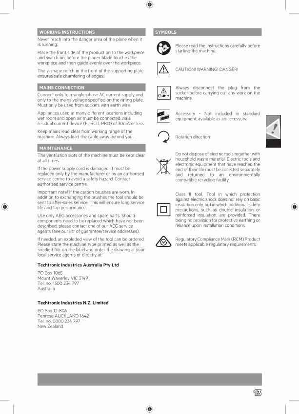
SYMBOLS
Please read the instructions carefully before starting the machine.
CAUTION! WARNING! DANGER!
Always disconnect the plug from the socket before carrying out any work on the machine.
Accessory - Not included in standard equipment, available as an accessory.
Rotation direction
Do not dispose of electric tools together with household waste material. Electric tools and electronic equipment that have reached the end of their life must be collected separately and returned to an environmentally compatible recycling facility.
Class II tool. Tool in which protection against electric shock does not rely on basic insulation only, but in which additional safety precautions, such as double insulation or reinforced insulation, are provided. There being no provision for protective earthing or reliance upon installation conditions.
Regulatory Compliance Mark (RCM).Product meets applicable regulatory requirements.

Techtronic Industries Australia Pty Ltd31 Gilby Road, Mount Waverley, VIC 3149Australia
Techtronic Industries N.Z. Limited2 Landing Drive, MangereAuckland, 2022, New Zealand
www.aegpowertools.com.auwww.aegpowertools.co.nz
AEG is a registered trademark used under license from AB Electrolux (publ).