Embed Size (px)
Citation preview

PREMIUM WIRED ALARM SYSTEM (PL4)
Contents Section 1 – Overview of System
1.1 Safety statement
1.2 Kit Contents
1.3 Tools Required
1.4 System Features
Section 2 – Planning your Installation 2.1 Location of components
2.2 Planning the location for the system components
Section 3 – Installing the System 3.1 Control Unit
3.2 Movement Detector/PIR
3.3 Door/Window Contact Detector
3.4 External Siren & Strobe
3.5 Testing the System
Section 4 – Using the System 4.1 User PIN
4.2 Changing the User PIN
4.3 Set / Clear chime Zones
4.4 Set / Clear Home-Bypass Zones
4.5 Set / Clear bypass Zones
4.6 Display bypass Zones
4.7 Display Zones with faulty devices
4.8 Display Home-Bypass Zones
4.9 Set delay time
4.10 Set siren & strobe duration time
4.11 Walk Test command
4.12 Clear the Alarm Hold Indications
4.13 Panic alarm
4.14 Silencing the System
4.15 Arm (set) the Alarm System while Exiting the House
4.16 Disarm (unset) the Alarm System while Entering the House
4.17 Arm (set) the Alarm System when you are Inside the House
4.18 Summary of the zones in different mode
4.19 Summary of Factory Settings
4.20 Status LED indications
Section 5 – Maintenance
Section 6 – Extending the System
Section 7 – Troubleshooting
Section 8 – Specifications
APPENDIX
- 2 -
SECTION 1 – OVERVIEW OF SYSTEM
The Response Premium Wired Alarm system is an indoor alarm system based on patent technology to
give exceptional levels of protection and reliability. It is a fuseless system with special electronic
circuitry for short-circuit protection. It is simple to use, easy to install, no special tools or training is
required.
IMPORTANT – Please read this manual carefully, in full, before commencing Installation. You will find
installation easier if you follow these steps in the sequence shown.
1.1 Safety
Before proceeding with the installation, please note the following safety warnings:
DO NOT connect the mains supply directly to the products, this will cause permanent damage to the
products. Control panel, Adaptor, Movement Detector and Door/Window contact are for indoor use only. Avoid
mounting location which can expose these product to splashing or dripping liquid.
Do not remove cover of the external siren when the strobe is flashing, do not touch the PCB zenon circuitry
in the external siren to avoid shock.
Always follow the manufacturer’s advice when using power tools and wear suitable Protective equipment
(e.g. safety goggles) when drilling holes, etc. The use of ear defenders is advisable when working in close
proximity to the Siren due to high sound level.Before drilling holes in walls, check for hidden electricity
cables and water pipes. The use of a cable/pipe locator is advisable if in doubt. Batteries (battery pack or
batteries installed) shall not be exposed to excessive heat such as sunshine, fire or the like; danger of
damage if battery is incorrectly replaced. Replace only with the same or equivalent type. (Do not mix
batteries type).
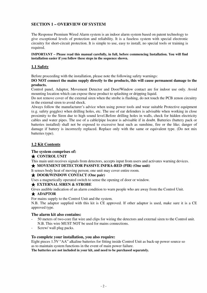
1.2 Kit Contents
The system comprises of: ★★★★ CONTROL UNIT
This main unit receives signals from detectors, accepts input from users and activates warning devices. ★★★★ MOVEMENT DETECTOR PASSIVE INFRA-RED (PIR) (One unit)
It senses body heat of moving person; one unit may cover entire room. ★★★★ DOOR/WINDOW CONTACT (One pair)
Uses a magnetically operated switch to sense the opening of door or window. ★★★★ EXTERNAL SIREN & STROBE
Gives audible indication of an alarm condition to warn people who are away from the Control Unit. ★★★★ ADAPTOR
For mains supply to the Control Unit and the system.
N.B. The adaptor supplied with this kit is CE approved. If other adaptor is used, make sure it is a CE
approved type.
The alarm kit also contains: - 50 meters of two-core flat wire and clips for wiring the detectors and external siren to the Control unit.
N.B. This wire MUST NOT be used for mains connections.
- Screw/ wall plug packs.
To complete your installation, you also require: Eight pieces 1.5V “AA” alkaline batteries for fitting inside Control Unit as back-up power source so
as to maintain system functions in the event of main power failure. The batteries are not included in your kit, and need to be purchased separately.

- 3 -
1.3 Tools Required The following tools are required for installation: ★ Large & small flat bladed screwdrivers and cross point screwdrivers ★ Hammer ★ Power drill ★ Drill bits – 4mm & 6mm ★ Wire cutters and wire stripper ★ Eye protection (recommended when using a power drill or hammer)
1.4 System Features ★ Simple and effective Four-zone system with the new two-wire technology. ★ All system components (sensors, sirens) are connected to the Control Unit via two-core
non-polarity flat wires. Wiring and installation of the system is extremely simple and easy. ★ Control Unit has built-in keypad with status LEDs and zone indicators. Low battery and
tamper attempts will be indicated by the status LEDs. ★ Push-button “HOME”, “OUT” and “OFF” three mode operation. ★ “HOME” and “OUT” modes are pre-programmed for user convenience. ★ At “OFF” mode, door chime function is available. ★ All sensors, sounders are 24 hour line-protected and fully supervised. Any attempt to interfere
with the system, such as cutting the connecting wires or opening any of the PIR detectors,
will trigger the alarm and be identified by flashing LEDs and zone indicator. ★ No fuse to burn. Short-circuit tamper attacks to any zone sensor will trigger the alarm and be
identified by flashing LEDs and zone indicator, but the operation of the rest of the system is
protected. ★ Two User PINs allocated for disarming (unsetting) the system. ★ Individual zones can be set to “HOME-BYPASS” or “BYPASS”; for example, the up-stairs
detectors can be set to “HOME-BYPASS” at night. ★ Two PIR motion detectors can be connected to one zone, therefore the system can be
expanded to have four PIRs plus many magnetic contacts.
MOVEMENT DETECTOR
PASSIVE INFRA-RED (PIR)
CONTROL UNIT
DOOR/WINDOW
CONTACTS
EXTERNAL SIREN & STROBE 15VAC ADAPTOR

- 4 -
SECTION 2 – PLANNING YOUR INSTALLATION If you are replacing an old Wired Alarm System, it is possible to re-use the existing installed wiring
for the Detector to save installation time. However ensure the cores of these existing cables are at
least 26AWG. When re-using, ensure each pair of cores are correctly marked up when connecting a
detector to the Control Panel unit.
2.1 Location of components Control Unit – Location In choosing a suitable location you should bear in mind: ★ The user needs to reach the Control Unit easily within the allocated time, when entering and
leaving the premises. ★ The Control Unit should not be visible from the exterior of the protected premises. ★ All detectors and the external siren must be wired to the Control Unit. ★ The Control Unit needs to be connected to an AC main via a CE approved adapter.
Having chosen the location do not mount at this stage.
Movement/Passive Infra Red Detector (PIR) – Location
★ The detector should not be mounted near to large metal objects or on metal surfaces. It needs
to be mounted on a wall or in a corner at a height of approximately 2 to 2.5meters for the best
general coverage in an average room. The detector has been designed to avoid false alarms,
nevertheless, it is best to avoid looking directly at sources of heat such as fires and boilers,
and always try to keep away from a window. A PIR can look at a radiator but should not be
sited above one.
★ Do not site a PIR where its field of view may be obstructed (e.g. by curtains). Also note that
PIRs work best when sensing movement across rather than along their detection beams. You
need to consider the need to wire these units back to the Control Unit.
Detection Area of PIR
Having chosen the location do not mount at this stage.
- 5 -
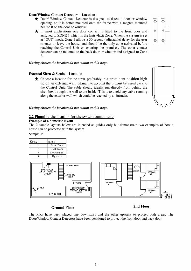
Door/Window Contact Detectors – Location ★ Door/ Window Contact Detector is designed to detect a door or window
opening, so it is better mounted onto the frame with a magnet mounted
next to it on the door or window.
★ In most applications one door contact is fitted to the front door and
assigned to ZONE 1 which is the Entry/Exit Zone. When the system is set
at “OUT” mode, Zone 1 allows a 30 second (adjustable) delay for the user
to enter or leave the house, and should be the only zone activated before
reaching the Control Unit on entering the premises. The other contact
detector can be mounted to the back door or window and assigned to Zone
2.
Having chosen the location do not mount at this stage.
External Siren & Strobe – Location
★ Choose a location for the siren, preferably in a prominent position high
up on an external wall, taking into account that it must be wired back to
the Control Unit. The cable should ideally run directly from behind the
siren box through the wall to the inside. This is to avoid any cable running
along the exterior wall which could be reached by an intruder.
Having chosen the location do not mount at this stage.
2.2 Planning the location for the system components Example of a domestic layout The 2 sample layouts below are intended as guides only but demonstrate two examples of how a
house can be protected with the system.
Sample 1:
Zone Area1 Front Door2 Back Door3 Downstairs4 Upstairs
The PIRs have been placed one downstairs and the other upstairs to protect both areas. The
Door/Window Contact Detectors have been positioned to protect the front door and back door.
Ground Floor 2nd Floor

- 6 -
Sample 2:
Zone Area1 Front Door2 Back Door3 Living Room4 Bedroom
The Zone 3 PIR has been placed in the Dining/Living room to protect this general area. The Zone 4
PIR has been placed in Bedroom #1 (Master Bedroom) to protect the personal valuables there. Zone 4
is set as “Home-Bypass zone” so that the zone 4 PIR is disabled when the system is set at “HOME”
mode. The Door/Window Contact Detectors have been positioned to protect the front door and back
door.
DOOR / WINDOW
CONTACT DETECTOR
(ZONE 1)
ENTRANCE HALL
ZONE 3
DOOR / WINDOW
CONTACT
DETECTOR
(ZONE 2)
ZONE 4

- 7 -
SECTION 3 – INSTALLING THE SYSTEM
3.1 Control Unit ★ Remove and retain the two holding screws from front cover of Control Unit and carefully
hinge off the front cover.
★ Disconnect the battery snap connecting the battery holder. Take out the battery holder.
(Illustration 1)
★ Place the Control Unit Mounting Template Sheet on the wall at the chosen location. Mark and
drill holes for the three mounting screws. Put in the wall plugs and have the two mounting
screws at the top (the hanging screws) inserted, leaving the two screws to protrude by about
5mm.
★ Aligning the Control Unit with the mounting guidelines on the template sheet and hang the
Control Unit onto the two hanging screws. (Illustration 2)
N.B. Do not put in the third mounting screw (the final fixing screw at the lower part of the
Control Unit) until after all the wirings to the Control Unit have been done, because you may
need to take the Control Unit off the hanging screws to facilitate the wiring.
Illustration 1 Battery holder
Illustration 2
CONTROL UNIT
Remove holding screws and hinge off front cover

- 8 -
★ Have all the sensors (Magnetic Contacts, PIRs) and accessories (External siren & strobe,
dialer, if fitted) wired up (as per Section 3.2, 3.3 and 3.4 that follows) and connected to the
corresponding terminals in the Control Unit (Illustration 3). Also wire up the Main Power
Adaptor to the Control Unit, but DO NOT plug in the adaptor to the main supply until all
connections are completed and all units properly mounted and front cover of Control Unit
closed and secured.
Note : The control unit has a 2 minute warm-up period after it is powered up.
WARNING: All connection to the mains should be made in accordance with all relevant
wiring regulations. The Control Unit must never be operated from the mains with the front
cover removed.
Illustration 3: Part Identification (wiring reference) * All connections are simply by 2 non-polarity flat wires only.
NOTE 1: For connecting two pieces Magnetic Contacts to any of Zone 1 or Zone 2, see Illustration 10
on page 11.
NOTE 2: The Illustration shows one piece of 2-wire PIR detector is connected to each of Zone 3 and
Zone 4; and therefore the PIR zone slide switches opposite the two PIR zone (Zone 3 and
Zone 4) terminals are put in position 1.
For connecting two pieces PIR to the same zone, you need to put the corresponding slide
switch to position 2. See Illustration 7 on page 10 for wiring.

- 9 -
Connect the two
wires to these
two switch terminal
Illustration 6 Illustration 6
★ After all the wirings are done, put in the final fixing screw (at the lower part of the Control
Unit) to secure the mounting. ★ Plug in 8 pieces AA alkaline battery into the battery holder and put it back into the Control
Unit connecting it with the battery snap. ★ Put back the front cover carefully and secure it with the two holding screws, complete with
the screw covers (plugs). Tear off the mounting template sheet.
3.2 Movement Detector/PIR ★ Remove and retain the screw from the bottom of the PIR and lift off the cover. ★ Carefully remove the electronic module from its retaining clips, ensuring not to touch the
pyroelectric sensor (Illustration 4).
Illustration 4 Illustration 5
★ Use mounting points “A”, if you are fitting the detector in a corner. Use mounting points “B”,
if you are fitting the detector on a flat surface. Use a small drill to create two fixing holes at
the mounting points (Illustration 5). ★ Hold the base of the PIR in the chosen position, ensuring that the front of the PIR will face
towards the center of the protected area, mark and drill two fixing holes in the wall. Choose
one of the cable entry holes “C” and make a third hole in the detector base. Put one end of the
2-core wire through this hole “C”, then secure the PIR to the wall using two screws and wall
plugs provided. ★ Replace the electronic module into the retaining clips, ensuring that it is correctly positioned
and firmly seated. ★ If required, select the PIR LED “ON” or “OFF” option and the sensitivity (pulse count) by
setting the corresponding jumpers on the electronic module. Note that Pulse 1 option is more
sensitive than the pulse 4 option. Pulse 1 option is used when it is necessary to activate an
alarm on the first detected pulse, or in high security installations – where fast “catch”
performance is of greatest importance. Pulse 2 or 4 settings provides improved protection
against false alarms caused by all types of environmental disturbances. (Illustration 6)
Pulse Count
Pulse 1
Pulse 2
Pulse 4
PYROELECTRIC
SENSOR

- 10 -
★ Connect the 2 wires to the PIR, polarity is not important. ★ Run the cable back to the Control Unit, fixing the cable with cable clips and enter the wire
into the back of the Control Unit through any convenient cable hole. ★ Connect to zone 3 or zone 4 terminals in the Control Unit as required, connection polarity is
not important. See Illustration 3 on page 8 ★ In the Control Unit, against each of the two PIR connection terminals (zone 3 and zone 4),
there is a 3-position (0,1,2) slide switch. These switches are factory pre-set at position “0”
when no PIR is connected. When connecting one piece of PIR to the zone, you need to set the
corresponding switch to position “1”. When connecting 2 pieces of PIR to the same zone
terminals, put the corresponding switch to position “2”. The wiring to connect two pieces of
PIR to one same zone terminals are as Illustration 7.
� When the two PIRs are running in the same direction:
� When the two PIRs are running in opposite directions:
Illustration 7 ★ Replace cover on PIR and refit the retaining screw.
3.3 Door/Window Contact Detector ★ Choose the location for each magnetic contact (remembering the need to wire them back to
the Control Unit). Each contact consists of a magnetically-operated switch (with screw
terminals at the back) and a magnet in an identical housing. ★ The switch (the part with screw terminals and cable) should be mounted on the frame. The
magnet should be mounted on the door or window itself directly opposite the switch, no more
than 8mm apart when the door or window is closed (Illustration 8). Mark two mounting holes
for the magnet on the door or window and two mounting holes for the switch on the frame.
Illustration 8
(Switch at
Position 2)
(Switch at
Position 2) (Switch at Position 2)
WINDOW FRAME

- 11 -
★ Choose a convenient entry point for the cable on the switch housing and carefully remove
part of the plastic using a sharp knife to create a hole (Illustration 9). Connect the 2 wires to
the two screw terminals.
Illustration 9
★ Fixed the contact and magnet in position using the four mounting screws provided. ★ Run the cable back to the Control Unit. Remove the jumper pre-connected to the
corresponding terminals at the zone 1 and/or 2. ★ Connect to zone 1 or zone 2 terminals of the Control Unit as required. Connection polarity is
not important. See Illustration 3 on page 8. ★ If two magnetic contacts need to be wired to one same zone (zone 1 or zone 2), wire them up
in serial connection as Illustration 10.
Illustration 10
3.4 External Siren & Strobe ★ Remove the cover retaining screws from the side of the siren cover (Illustration 11). Take off
the cover from the siren baseplate.
★ Use the siren baseplate as a template to mark and drill two fixing holes (Illustration 11) in the
wall at the chosen position. For mounting the siren outside the house, drill a further hole
through the wall directly behind the siren for the 2 x 2 cores of cables to run through from the
Control Unit to the Siren. ★ Mount and fix the siren with the screws and wall plugs provided. ★ The siren duration can be selected with jumper to approximately 1/3/10 minutes, whilst the
strobe will flash continuously. Summary of siren/strobe duration as below:
Illustration 11
Fixing Holes Jumper Setting
for Siren Duration
Terminal
Connection

- 12 -
★ Different timer settings for the strobe/siren can be programmed (ref Section 4.10) ★ Connect the two x 2 cores cable (2 for signal, 2 for tamper) to the terminals inside the siren,
ensure you mark up one of the 2 core sets so you know which one corresponds to the tamper
and which one to the power (DC IN) terminals in the control panel, then pass through the 2 x
2 core cables through the wall, and connect the other end of the cable to the corresponding
terminals in the Control Unit. See Illustration 3 on page 8. ★ Remove the pre-link jumper at TAMP terminal in control panel to activate the tamper
function for external siren. ★ Replace cover on siren and refit retaining screw.
3.5 Testing the System ★ After installation is completed, plug in the main power supply adaptor. The “POWER”
indicator will illuminate and the “OFF” mode LED (green) will also light up, showing the
system is in “OFF” mode. Wait about two minutes for the system to get ready.
Testing the detectors
� With the system in “OFF” mode (“OFF” mode LED illuminated), press “*”, “6”, “1”, “#”.
Two short beeps acknowledge acceptance of command and walk test mode
activated. � Trigger all the detectors (magnetic contacts and PIRs) one by one. The corresponding zone
indicators on the Control Unit should light up.
� If the zone indicator does not light up, check the corresponding detector and wiring. Fix the
problem and test again.
� Exit walk test mode by pressing “*”, “6”, “#”. Two short beeps with zone indicators turned
off indicate walk test mode exited.
� Repeat the test periodically where necessary.
Testing the external siren & strobe � Use the Panic Alarm command (pressing “*” and “#” simultaneously) to trigger the alarm
for testing. The built-in siren in the Control Unit will sound immediately with all four zone
indicators illuminated and the external siren will sound 30 seconds later. The alarm sound
will stop automatically after 3 minutes (factory setting, alarm duration timer is adjustable).
To stop the alarm sound & flash, enter User PIN at the Control Unit. To clear the zone
indicators, enter “*”, “8”, “#”.
External Siren duration
Programming Key at
Control Unit (with
the system in
“OFF” mode)
Internal Siren
(in Control
Unit) duration
Strobe duration
Jumper Setting
on (1 Minute)
Jumper Setting
on (3 Minutes)
Jumper Setting
on (10 Minutes)
1.
Approx. 3
minutes
Flash continuously
until the User PIN
Code is entered at
the Control Unit
Approx.1
minute
Approx. 3
minutes
Approx. 10
minutes
2.
Approx. 1
minute
Approx.1
minute
Approx. 1
minute
Approx. 1
minute
Approx. 1
minute
3.
Approx. 3
minutes
Approx. 3
minutes
Approx. 1
minute
Approx. 3
minutes
Approx. 3
minutes
4.
Approx. 10
minutes
Approx. 10
minutes
Approx. 1
minute
Approx. 3
minutes
Approx. 10
minutes
Important: If the Security System has been reset to factory default settings (Reference: instruction manual page
17) please activate the above strobe/siren alarm hold duration timer command again.

- 13 -
0 2 3 4 5 6 7 8 *
9 8 9 0 6 7 8 9 *
1 *
SECTION 4 – USING THE SYSTEM ★ Note: If you enter an invalid command or the command is incomplete, the Control Unit will
give a long, low-pitched beep (“error” tone). For valid commands, the Control Unit will
acknowledge acceptance with two short beeps, and if the command is related to one of the
four detection zones, the corresponding zone indicator will also flash once for confirmation.
4.1 User PIN ★ User PIN can disarm the system and change to OFF mode. ★ Two user PINs are allocated for this system.
Note: The factory setting for the User PIN is 1234 and 7890.
4.2 Changing the User PIN ★ User is highly recommended to change both of the PINs numbers when using it for the first
time. The User PIN is set to 1234 and 7890 at the factory and you may change them to any
four-digit numbers of your choice. The User PIN will be changed back to their respective
default values “1234” and “7890” if the power of the Control Unit has been reset.
With the system in “OFF” mode,
����Change the 1st user PIN as follows:
Two short beeps indicate the command is successful and a long beep indicates the command is
rejected.
����Change the 2nd
user PIN as follows:
Two short beeps indicate the command is successful and a long beep indicates the command is
rejected.
4.3 Set / Clear chime Zones ★ The system can be set so that, when in “OFF” (Unset) mode, if a zone is triggered, the Control
Unit with give a chime tone. This can be done for any of the four zones.
With the system in “OFF” mode,
����Set chime flag for any Zone as follows:
Two short beeps and the corresponding zone indicator flashes once to confirm.
����Clear chime Zones as follows:
Two short beeps for confirmation.
Note: The chime Zone is Zone 1 at factory setting.
#
Default New PIN NO.
1
#
Default New PIN NO.
7
Zone No. (1~~~~4) #
* 1 #

- 14 -
2 *
3 *
4 1 #
4 2 #
4.4 Set /Clear Home-Bypass Zones ★ When the zone is set to Home-Bypass zone, the corresponding detector will not be activated
in HOME mode. However, when the system is put in “OUT” mode, the Home-Bypass zone
detector will be operative and, when triggered, will signal the Control Uint to alarm after 30
seconds (adjustable) delay time.
.
With the system in “OFF” mode,
����Set Home-Bypass Zone for any of Zone 2 to 4 as follows:
Two short beeps and the corresponding zone indicator flashes once to confirm.
����Clear Home-Bypass Zones as follows:
Two short beeps for confirmation.
Note: Zone 4 is set as Home-Bypass Zone at factory setting.
4.5 Set / Clear Bypass Zones ★ When a zone is set to Bypass Zone, the corresponding detector will not be activated in ANY
mode.
With the system in “OFF” mode,
����Set Bypass Zone for any of Zone 2 to 4 as follows:
Two short beeps and the corresponding zone indicator flashes once to confirm.
����Clear Bypass Zones as follows:
Two short beeps for confirmation.
4.6 Display Bypass Zones
With the system in “OFF” mode,
����Check which zones have been set as Bypass Zones as follows:
Two short beeps and the zone indicators for the Bypass Zones will illuminate for a few seconds.
4.7 Display Zones with faulty devices
With the system in “OFF” mode,
���� Check which, if any, zone detector in the system has any problem as follows:
Two short beeps and the Zone indicator for any zone with faulty devices will illuminate for a few
seconds.
Zone No. (2~~~~4) #
* 2 #
Zone No. (2~~~~4) #
* 3 #
****
****

- 15 -
5 1 N #
5 2 N #
4 3 #
6 *
4.8 Display Home-Bypass Zones
With the system in “OFF” mode,
���� Check which zones have been set as Home-Bypass Zones as follows:
Two short beeps and the zone indicators for the Home-Bypass Zones will illuminate for a few
seconds.
4.9 Set delay time ★ When the system is put in “OUT” mode, there is a 30 seconds (factory preset, can be changed
by user to 15 or 45 seconds) delay time before the alarm will be activated. The delay time is
to give the user enough time to exit or enter the premises before the alarm is activated. User
may select the delay timer as follows:
With the system in “OFF” mode,
����Set entrance / exit delay timer:
N =1 for 15 sec
N =2 for 30 sec
N =3 for 45 sec Two short beeps indicate the command is successful and a long beep indicates the command is
rejected.
4.10 Set siren & strobe duration ★ The siren & strobe is preset at the factory to a duration of 3 minutes. The alarm will stop by
itself after this preset duration and the alarm hold indication (illuminated zone indicator) will
be on. To change the duration, do as follows:
With the system in “OFF” mode,
����Set siren & strobe duration timer:
N =0 for continuously (set the siren duration by jumper selection, refer Section 3.4, page 12.)
N =1 for 1 min
N =2 for 3 min
N =3 for 10 min Two short beeps indicate the command is successful and a long beep indicates the command is
rejected.
4.11 Walk Test command
With the system in “OFF” mode,
����Enable walk test mode as follows:
Two short beeps confirm command is accepted and Walk Test mode is activated.
����Trigger all the zones and the corresponding zone indicators will illuminate.
����Exit walk test mode as follows:
Two short beeps and zone indicators will turn off, Walk Test mode is exited.
****
****
****
#
* 6 #
1

- 16 -
#
4.12 Clear the Alarm Hold Indications ★ To clear the alarm hold indications (illuminated zone indicators), do as follows:
With the system in “OFF” mode,
����Key in the following buttons:
Two short beeps and all zone indicators turn off.
4.13 Panic alarm ★ Should you need to attract attention, the full alarm signal can be activated at emergency by
pressing * and # together.
����Press & simultaneously, the system will sound immediately and all four zone
indicators will illuminate. The external sounder and the telephone dialer (if one is fitted) will be
triggered 30 seconds later.
4.14 Silencing the System ★ When the alarm is triggered, the user has to enter the PIN at the Control Unit to cancel the
alarm sound and flash. ★ If the alarm has not been cancelled, the alarm sound and flash will stop by itself after the
preset alarm duration timing (3 minutes at the factory setting, adjustable by user) and the
alarm hold indication (zone indicator) of the intruded zone will illuminate. ★ To clear the alarm hold indication; enter the PIN and the control panel will back to “OFF”
mode, then key in two short beeps and all indicators turn off.
4.15 Arm (set) the Alarm System while Exiting the House
����Press “OUT” key for a while.
The count down warning sound (exit delay) will start and the “Zone 1” indicator will illuminate
while the entry/exit zone (zone 1) is opened.
����Leave the house and close the door within the exit delay time (30 seconds at factory setting, user
adjustable). Both PIRs & Magnetic Switches are activated for protection after the exit time
expires.
Note: The system cannot enter OUT mode if zone 2 and/or 4 is triggered (Zone 2 and 4 indicators
illuminated).
4.16 Disarm (unset) the Alarm System while Entering the House When you open the entrance door of zone 1, the count down warning sound (entry delay time) will
be on.
����Enter your four-digit User PIN within the delay time (30 seconds at factory setting, user
adjustable). System changes to “OFF” mode (OFF mode status LED illuminated).
4.17 Arm (set) the Alarm System when you are Inside the House
���� Press “HOME” key for a while.
Both Magnetic Switches and PIRs are activated to protect your home except the Home-Bypass
zone.
����You may set Home-Bypass zone for the areas where you will be in.
Note: The system cannot enter Home mode if zone 1 or 2 are opened.
*
****
8 #
* # 8
- 17 -
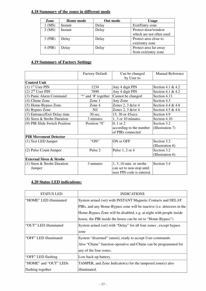
4.18 Summary of the zones in different mode
Zone Home mode Out mode Usage
1 (MS) Instant Delay Exit/Entry zone
2 (MS) Instant Delay Protect door/window
which are not often used
3 (PIR) Delay Delay Protect area close to
exit/entry zone
4 (PIR) Delay Delay Protect area far away
from exit/entry zone
4.19 Summary of Factory Settings
Factory Default Can be changed
by User to
Manual Reference
Control Unit
(1) 1st User PIN 1234 Any 4 digit PIN Section 4.1 & 4.2
(2) 2nd
User PIN 7890 Any 4 digit PIN Section 4.1 & 4.2
(3) Panic Alarm Command ‘*’ and ‘#’ together Cannot be changed Section 4.13
(4) Chime Zone Zone 1 Any Zone Section 4.3
(5) Home-Bypass Zone Zone 4 Zones 2, 3 &/or 4 Section 4.4 & 4.8
(6) Bypass Zone Nil Zones 2, 3 &/or 4 Section 4.5 & 4.6
(7) Entrance/Exit Delay time 30 sec. 15, 30 or 45secs Section 4.9
(8) Siren & Strobe Duration 3 minutes 1, 3 or 10 minutes Section 4.10
(9) PIR Slide Switch Position Position “0” 0, 1 or 2
according to the number
of PIRs connected
Section 3.2
(Illustration 7)
PIR Movement Detector
(1) Test LED Jumper “ON” ON or OFF Section 3.2
(Illustration 6)
(2) Pulse Count Jumper Pulse 2 Pulse 1, 2 or 4 Section 3.2
(Illustration 6)
External Siren & Strobe
(1) Siren & Strobe Duration
Jumper
3 minutes 1, 3 ,10 min. or strobe
can set to non-stop until
user PIN code is entered.
Section 3.4
4.20 Status LED indications:
STATUS LED INDICATIONS
“HOME” LED illuminated
System armed (set) with INSTANT Magnetic Contacts and DELAY
PIRs, and any Home-Bypass zone will be inactive (i.e. detectors in the
Home-Bypass Zone will be disabled, e.g. at night with people inside
house, the PIR inside the house can be set to “Home-Bypass”)
“OUT” LED illuminated System armed (set) with “Delay” for all four zones , except bypass
zone
“OFF” LED illuminated System “disarmed” (unset), ready to accept User commands.
Also “Chime” function operative and Chime can be programmed for
any of the four zones.
“OFF” LED flashing Low back-up battery.
“HOME” and “OUT” LEDs
flashing together
TAMPER, and Zone Indicator(s) for the tampered zone(s) also
illuminated.

- 18 -
SECTION 5 – MAINTENANCE Once every three months, ★ Test all detectors. ★ Test siren & strobe unit
Additionally, ★ Check backup batteries condition yearly to ensure no leakage, replace the alkaline batteries
when “OFF” status LED keeps on flashing, Do not mix batteries type.
SECTION 6 – EXTENDING THE SYSTEM
A number of accessories are available to expand your system to suit your exact requirements. ★ Wired PIR Accessory (PW2) – covers a large area, easy to wire. ★ Wired Door/Window Contact Accessory Pack (PW1) – small, robust and reliable. ★ Dummy Siren (PW3) – acts as an external visual deterrent.
SECTION 7 – TROUBLESHOOTING
Control Unit Possible causes & cures
Power Indicator and all status LEDs do not light
up – unit totally “dead”
No power supply to unit. Check connections to
mains and backup battery.
Power Indicator does not light up and one of the
status LEDs (“HOME” or “OUT” or “OFF”)
illuminated.
Main supply off, unit operating from backup
battery.
Check mains connections /adaptor.
When power is applied, siren sounds and “OFF”
status LED (green) illuminated, “HOME” (red)
and “OUT” (red) LEDs are flashing.
Tamper fault on PIR detectors or external siren.
Check the wiring of the PIR zones (Zones 3 and
4) to Control Unit. Check the PIR detector cover
is correctly fitted and securely fastened. Check
PIR switch is set at correct position. Check the
tamper terminal of external siren wiring to control
unit. Ensure the tamper cable and signal cable are
correctly connected to its corresponding terminals
in the control panel.
“OFF” status LED (green) flashing. Low backup battery condition in Control Panel,
replace batteries as soon as possible.
When “OUT” key is pressed, unit will not arm,
give “error” tone (one long beep) and zone 2
and/or zone 4 indicator(s) illuminates.
Indicated zone(s) open/triggered.
Check that zone 2 and/or 4 are cleared
(door/window closed, no movement near PIR),
and try again. Check PIR switch is set at correct
position.
When “HOME” key is pressed, unit will not arm,
give “error” tone (one long beep) and zone 1
and/or zone 2 indicator(s) illuminates.
Indicated zone(s) open.
Check that all magnetic contacts (zone 1 and zone
2) are closed, and try again.
PIR Detector Possible causes & cures
Does not detect movement (PIR’s LED does not
light up when triggered).
Is the PIR’s LED turned off?
PIR causes false “intruder” alarms. Check that PIR is not pointed at heat sources or
moving object, and is not mounted above a
radiator or other heater. Check PIR switch is set at
correct position.
PIR will not trigger alarm when the system is set
(armed).
PIR not yet warms up.
Wait for a couple of minutes and trigger the PIR
again.
PIR detects movement (LED light up) but control
panel does not response/no alarm.
Check the PIR switch is not set at 0. PIR switch
must set at correct position.

- 19 -
Magnetic Contact Detector Possible causes & cures
Does not detect opening of door or window
(corresponding zone indicator does not illuminate
when door/window is opened, whilst system is
armed or during walk test).
Check that magnet is correctly positioned.
Check that the jumper pre-connected to zone 1 &
2 terminals at control panel are removed
Leave the jumper on the terminals if no magnetic
contact is connected to the zone.
External Siren & Strobe Possible causes & cures
NO sound & flash goes off during test or full
alarm.
Check the wiring and connections of the unit.
Ensure the tamper cable and signal cable are
correctly connected to its corresponding terminals
in the control panel.
Remark: If you have any problem with the system, take off the battery and disconnect the
mains for couple of minutes. The system will reset to factory default settings.
SECTION 8 – SPECIFICATIONS
Control Unit
Type Microprocessor based control unit with new two-wire technology
Housing ABS
Zones 4 Alarm Zones (Expandable by connecting 2 PIRs to each of
Zones 3 and 4)
Entry/Exit Delay 15, 30, 45 seconds, programmable
Siren Duration 1, 3, 10 minutes, programmable
Siren/Strobe Outputs 12VDC
Operating Temperature -5oC to + 40
oC
PIR
Type Dual Pyroelectric element with hemispherical lens and new
two-wire technology
Housing ABS
Adjustments Pulse Count (1, 2 or 4)
Test LED Selectable (on/off)
Mounting height 2-2.5m
Detection Range Up to 12m
View Angle 110o
Operating Temperature -5oC to + 40
oC
Door/Window Contact Detector Type Magnetically - actuated switch
Housing ABS
Operating Temperature -5oC to + 40
oC
External Siren & Strobe Unit Type Piezo electronic external siren & Xenon Strobe Module
Housing ABS
Siren Output 110dB min. at 1m
Siren Cut-off Timer Jumper Selectable 1/3/10 minutes (approx)
Strobe Flash Rate Around 110 flashes/min.
Operating Temperature -10oC to + 50
oC
Rain Protection IP44

- 20 -
APPENDIX
Zone - Location Table :
Zone Number Location Location
1
2
3
4
Disposal and Recycling Batteries and waste electrical products should not be disposed of with household waste. Please
recycle where these facilities exist.
Check with your local authority or retailer for recycling advice.
Guarantee Novar ED&S undertakes to replace or repair at its discretion goods (excluding non
rechargeable batteries) should they become defective within 1 year solely as a result of faulty
materials and workmanship.
Understandably if the product has not been installed, operated or maintained in accordance
with the instructions, has not been used appropriately or if any attempt has been made to
rectify, dismantle or alter the product in any way the guarantee will be invalidated.
The guarantee states Novar ED&S entire liability. It does not extent to cover consequential
loss or damage or installation costs arising from the defective product. This guarantee does
not in any way affect the statutory or other rights of a consumer and applies to products
installed within UK and Eire only.
If an item develops a fault, the product must be returned to the point of sale with :
1. Proof of purchase.
2. A full description of the fault.
3. All relevant batteries (disconnected).
Novar Electrical Devices and Systems.
The Arnold Centre, Paycocke Road, Basildon, Essex SS14 3EA.
50044506 Rev.A
CUSTOMER HELPLINE
0844 736 9149 Most issues can be solved over the phone in a few minutes. Please contact
our Helpline Team on the above number for any installation and general
advice regarding our products
Lines open 9.00am to 5.00pm, Monday to Friday. Calls are charged at
service providers national rate.


![Exchange Ticketing Zenon[1]](https://img.pdfslide.us/doc/110x75/577d397a1a28ab3a6b99d3b6/exchange-ticketing-zenon1.jpg)