Embed Size (px)
Citation preview

PRL GLASS PANIC HANDLES
1
Panic handle installation instructions PL100-D
PRL Glass systems 251 Mason way
Phone: 800-433-7044 Fax: 626-968-9256 www.prlglass.com
City of industry, CA. 91746
DOOR MANUAL
PL100 PANIC HANDLE
PL100-D SERIES For all glass doors
Content of this manual:
DOOR FABRICATION ( panic handle installation ) - page 3
Parts list, tools & supplies required
Installation of handle to door
Actuator post alignment & nylon bushing selection
DOOR INSTALLATION - page 9
Door stop with manual strike
Header preparation for adjustable door stop with manual strike
Installation of panic strike & panic handle adjustment
Bolt adjustment for proper engaging with the strike
OPTIONAL—DOOR STOP WITH ELECTRIC STRIKE
Header preparation for adjustable door stop with electric strike
Installation & adjustment of door stop—strike
HANDLE CARE & MAINTENANCE
Care & cleaning
Stainless steel polished & brushed finish
Brass/bronze mirror polished & brushed (satin) finish
Oil rubbed bronze
Routine maintenance
Repair & replacement ( replacing lock cylinder )

PRL GLASS PANIC HANDLES
2
Panic handle installation instructions PL100-D
PRL Glass systems 251 Mason way
Phone: 800-433-7044 Fax: 626-968-9256 www.prlglass.com
City of industry, CA. 91746
Parts list
○Enclosed are the following parts:
○Flat head socket screw
○Actuator post with cylinder operating pin & handle return pin
with spring
○Nylon bushing
○Cylinder housing
○Adapter block with installation screws
○Threaded pin
○Exterior handle retainer with rubber bushing
○Exterior handle installation screw
Tools & supplies needed
○A set of allen wrenches
○A set of nylon bushings
○One 10 inch non marring channel lock pliers (optional)
○One spanner wrench

PRL GLASS PANIC HANDLES
3
Panic handle installation instructions PL100-D
PRL Glass systems 251 Mason way
Phone: 800-433-7044 Fax: 626-968-9256 www.prlglass.com
City of industry, CA. 91746
To begin installation, your door lite must be laid on a pair of saw horses with the exterior side of the door facing downward and the interior (panic side) facing upward.
Any and all applicable rails should be previously set, making sure to position the interior panic mounting hole in the rail towards the leading edge or strike side of the door.
!
Important information
Apply thread locker / Loctite
to all fasteners used on handles
interior & exterior
PRL GLASS PANIC HANDLES
4
Panic handle installation instructions PL100-D
PRL Glass systems 251 Mason way
Phone: 800-433-7044 Fax: 626-968-9256 www.prlglass.com
City of industry, CA. 91746
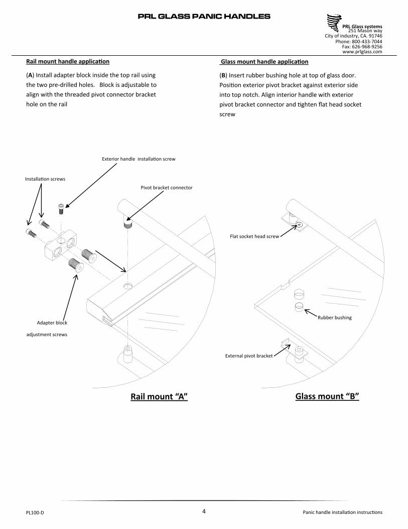
Rail mount handle application
(A) Install adapter block inside the top rail using
the two pre-drilled holes. Block is adjustable to
align with the threaded pivot connector bracket
hole on the rail
Glass mount handle application
(B) Insert rubber bushing hole at top of glass door.
Position exterior pivot bracket against exterior side
into top notch. Align interior handle with exterior
pivot bracket connector and tighten flat head socket
screw
Installation screws
Adapter block
adjustment screws
Flat socket head screw
External pivot bracket
Rubber bushing
Pivot bracket connector
Exterior handle installation screw
Rail mount “A” Glass mount “B”

PRL GLASS PANIC HANDLES
5
Panic handle installation instructions PL100-D
PRL Glass systems 251 Mason way
Phone: 800-433-7044 Fax: 626-968-9256 www.prlglass.com
City of industry, CA. 91746
Spanner wrench
Exterior handle retainer
Rubber bushing
Exterior handle
Triple hole bushing
1.– Insert the exterior horizontal handle retainer
with the rubber bushing through the interior side
into the horizontal handle & Hand tighten
2.– With adaptor block in place (see page 4) raise
exterior handle against face of glass & tighten
exterior installation screw with allen wrench
3.– Tightly secure exterior handle retainer with
spanner wrench
Spanner wrench
Exterior handle retainer
Rubber bushing
INSTALLING THE HANDLE
Triple hole bushing
Exterior handle
installation screw
Exterior handle
Installation screw
!
Important information
Apply thread locker / Loctite
to all fasteners used on handles
interior & exterior

PRL GLASS PANIC HANDLES
6
Panic handle installation instructions PL100-D
PRL Glass systems 251 Mason way
Phone: 800-433-7044 Fax: 626-968-9256 www.prlglass.com
City of industry, CA. 91746
4.– Position the interior panic handle over the pivoting
end of the exterior horizontal bar. Make sure to align
the hole on the pivoting projection. Insert the threaded
pin and tighten with an allen wrench
Please refer to actuator post alignment and
bushing configuration on page 7 & 8
This is a very important procedure.
( only one bushing to be used )
5.– Insert bushing into triple hole
6.– Lift the handle and insert actuator post containing cylinder
operating pin, return spring and return plunger into handle.
Place actuator base against glass over the triple hole bushing.
Cylinder housing
Triple hole bushing
Threaded pin
Cylinder operating pin
Plunger
Actuator post
Threaded pin
Allen wrench
Triple hole bushing

PRL GLASS PANIC HANDLES
7
Panic handle installation instructions PL100-D
PRL Glass systems 251 Mason way
Phone: 800-433-7044 Fax: 626-968-9256 www.prlglass.com
City of industry, CA. 91746
Hole
Center
418 Before proceeding to the actuator post
installation, it is now critical to verify the triple hole clamping alignment and assess which nylon bushing should be used. This hole alignment is important and to correct any misalignment holes, there are (4) different bushing inserts to choose from.
See below examples to help with your bushing selection to match what best suits your door.
A B C D
NYLON BUSHING SELECTION
Bushing “A” can be used if all holes at the top and center triple holes cutout line up
perfectly.
Bushing “B” can be used if the triple hole cutout is 1/16” off from left to right from edge of
door 4-1/8” required
Bushing “C” can be used when the height location of the triple
hole cut out is off 1/16” however the edge 4-1/8”
is correct
Bushing “D” can be used if both hole locations
are off by 1/16
4-1/8 from edge of door & vertical hole center
CRITICAL PROCEDURE
PRL GLASS PANIC HANDLES
8
Panic handle installation instructions PL100-D
PRL Glass systems 251 Mason way
Phone: 800-433-7044 Fax: 626-968-9256 www.prlglass.com
City of industry, CA. 91746
A
418
C
DB
actuator post
View from outside
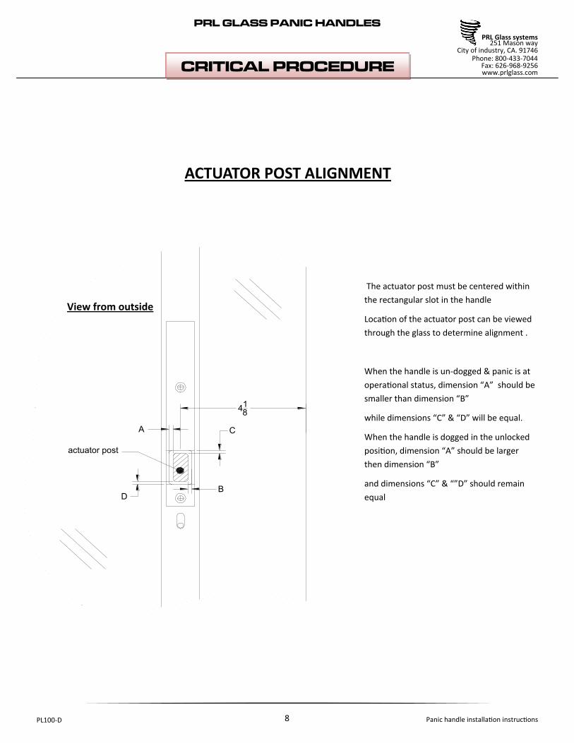
ACTUATOR POST ALIGNMENT
CRITICAL PROCEDURE
The actuator post must be centered within
the rectangular slot in the handle
Location of the actuator post can be viewed
through the glass to determine alignment .
When the handle is un-dogged & panic is at
operational status, dimension “A” should be
smaller than dimension “B”
while dimensions “C” & “D” will be equal.
When the handle is dogged in the unlocked
position, dimension “A” should be larger
then dimension “B”
and dimensions “C” & “”D” should remain
equal

PRL GLASS PANIC HANDLES
9
Panic handle installation instructions PL100-D
PRL Glass systems 251 Mason way
Phone: 800-433-7044 Fax: 626-968-9256 www.prlglass.com
City of industry, CA. 91746
DOOR INSTALLATION
To properly install the door you will find single or double adjustable door stops with screws & keys, which are supplied with the panic door installer manual. Make sure you have 1ea 1/8” allen wrench 1ea 1/4” allen wrench 1ea thread locker / Loctite
PARTS LIST
Single or double adjustable door stops with required installation screws. Keys, supplied with panic door installer manual.
PRL GLASS PANIC HANDLES
10
Panic handle installation instructions PL100-D
PRL Glass systems 251 Mason way
Phone: 800-433-7044 Fax: 626-968-9256 www.prlglass.com
City of industry, CA. 91746
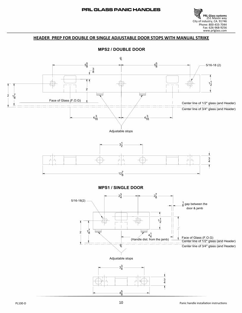
312
558
1278
CL
334
234
458
CL
112
Adjustable stops
Adjustable stops
34
34
MPS1 / SINGLE DOOR
MPS2 / DOUBLE DOOR
112
558
43
164
316
278
414
(Handle dist. from the jamb)
18
gap between the
door & jamb
2
Center line of 1/2" glass (and Header)
Center line of 3/4" glass (and Header)
178
2
Face of Glass (F.O.G)
Center line of 3/4" glass (and Header)
Center line of 1/2" glass (and Header)
2 178
5/16-18 (2)
5/16-18(2)
38
Face of Glass (F.O.G)
HEADER PREP FOR DOUBLE OR SINGLE ADJUSTABLE DOOR STOPS WITH MANUAL STRIKE
PRL GLASS PANIC HANDLES
11
Panic handle installation instructions PL100-D
PRL Glass systems 251 Mason way
Phone: 800-433-7044 Fax: 626-968-9256 www.prlglass.com
City of industry, CA. 91746
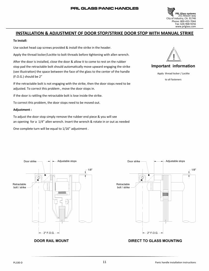
2" F.O.G. 2" F.O.G.
Door strike
Retractable
bolt / strike
1/8" 1/8"
Adjustable stops Door strike
Retractable
bolt / strike
Adjustable stops
DOOR RAIL MOUNT DIRECT TO GLASS MOUNTING
INSTALLATION & ADJUSTMENT OF DOOR STOP/STRIKE DOOR STOP WITH MANUAL STRIKE
!
Important information
Apply thread locker / Loctite
to all fasteners
To install:
Use socket head cap screws provided & install the strike in the header.
Apply the thread locker/Loctite to bolt threads before tightening with allen wrench.
After the door is installed, close the door & allow it to come to rest on the rubber
stop pad the retractable bolt should automatically move upward engaging the strike
(see illustration) the space between the face of the glass to the center of the handle
(F.O.G.) should be 2”
If the retractable bolt is not engaging with the strike, then the door stops need to be
adjusted. To correct this problem , move the door stops in.
if the door is rattling the retractable bolt is lose inside the strike.
To correct this problem, the door stops need to be moved out.
Adjustment :
To adjust the door stop simply remove the rubber end piece & you will see
an opening for a 1/4” allen wrench. Insert the wrench & rotate in or out as needed
One complete turn will be equal to 1/16” adjustment .

PRL GLASS PANIC HANDLES
12
Panic handle installation instructions PL100-D
PRL Glass systems 251 Mason way
Phone: 800-433-7044 Fax: 626-968-9256 www.prlglass.com
City of industry, CA. 91746
BOLT ADJUSTMENT FOR PROPER ENGAGING WITH THE STRIKE
2" F.O.G.
1/8" Door to header
or ceiling
clearance
DOOR RAIL MOUNT
Bottom of header
( Ceiling )
Factory set to
11/16- 3/4- for 1/8"
Door to header
or ceiling
clearance
A
C
B
If necessary, the retractable bolt can be adjusted. The centerline of the roller at the top of the retractable bolt should enter the
strike a minimum of 1/8”. The maximum upward adjustment is 3/4” when measuring from the top of the handle tubing to the top
of the bolt.
To adjust the retractable bolt
“A” remove the flat head screw at the top of the panic handle but do not remove the slotted head screw
“B” rotate the retractable bolt 360 degrees in either direction to obtain the desired height adjustment. Rotate bolt to align interior
threaded hole with countersunk hole in tubing.
“C” Replace flat head screw.
Note: if flat head screw is not securely replaced, the retractable bolt will randomly rotate, which will cause the bolt to improperly engage the strike.
!
Important information
DO NOT REMOVE THIS SCREW

PRL GLASS PANIC HANDLES
13
Panic handle installation instructions PL100-D
PRL Glass systems 251 Mason way
Phone: 800-433-7044 Fax: 626-968-9256 www.prlglass.com
City of industry, CA. 91746
SINGLE DOOR
71516
6
4
ADJUSTABLE STOPS
ADJUSTABLE STOPS
2332
2
558
558
558
11316
5/16-1 8 (3)
5/16-1 8 (2)
165
16
21
81
1414
718
DOUBLE DOOR
478
2332
OF DOOR OPENING
LEFT DOOR OPENING RIGHT DOOR OPENING
CL
HEADER PREP FOR DOUBLE DOOR & SINGLE ADJUSTABLE DOOR STOPS WITH ELECTRIC STRIKE

PRL GLASS PANIC HANDLES
14
Panic handle installation instructions PL100-D
PRL Glass systems 251 Mason way
Phone: 800-433-7044 Fax: 626-968-9256 www.prlglass.com
City of industry, CA. 91746
Header
FOLGER ADAM 310-1
Electric strike
with 3/4" straight keeper
87°Face of the strike keeper
factory preset @ 87°
Electric wires
Cover retaining screw
Door stop cover
Door stop
mounting bolts
Electric strike
mounting bolts
INSTALLATION & ADJUSTMENT OF DOOR STOP—STRIKE
DOOR STOP WITH ELECTRIC STRIKE
INSTALLATION
Remove cover retaining screw & door stop cover.
Install door stop—strike onto header using provided socket head cap screws
( Door stop mounting bolts shown on illustration). Apply thread locker / Loctite to
bolt threads prior to tightening with allen wrench. Replace door stop cover &
fasten with cover retaining screw.
!
Important information
Apply thread locker / Loctite
to all fasteners
Face of the strike keeper must be set @ 87degrees as illustrated
To replace strike
○ Turn off power to electric strike
○ Remove cover retaining screws & door stop cover
○ Remove door stop mounting bolts & gently lower door stop-latch keeper
Disconnect electrical wiring
○ Remove electric strike mounting bolts & install new strike
○ Reconnect wires to new electric strike using appropriate wire connectors
○ Apply thread locker / Loctite & tighten electric mounting bolts
○ Mount door stop / latch keeper in header & replace door stop cover
○ Turn on power to electric strike
○ Verify that the strike operates properly
IMPORTANT NOTE FOR ELECTRIC STRIKE REPLACEMENT

PRL GLASS PANIC HANDLES
15
Panic handle installation instructions PL100-D
PRL Glass systems 251 Mason way
Phone: 800-433-7044 Fax: 626-968-9256 www.prlglass.com
City of industry, CA. 91746
2" F.O.G. 2" F.O.G.
Retractable
bolt / strike
1/8"Adjustable stops
Retractable
bolt / strike
Adjustable stops
DOOR RAIL MOUNT DIRECT TO GLASS MOUNTING
FOLGER ADAM 310-1
Electric strike
with 3/4" straight keeper
1/8"
ADJUSTMENT OF DOOR STOP/STRIKE DOOR STOP WITH ELECTRICAL STRIKE
After door has been installed & comes to rest on door stop rubber
the retractable bolt should automatically move upward into the
strike as illustrated. The distance from the face of glass (F.O.G.) to
center of handle should be 2”
If retractable bolt is not fully engaging with the strike,
the door stops need to be moved in
if the door is rattling or the retractable bolt is lose inside the strike
door stops should be moved out.
Adjustment :
To adjust the door stop simply remove the rubber end piece & you
will see an opening for a 1/4” allen wrench. Insert the wrench &
rotate in or out as needed
One complete turn will be equal to 1/16” of adjustment .

PRL GLASS PANIC HANDLES
16
Panic handle installation instructions PL100-D
PRL Glass systems 251 Mason way
Phone: 800-433-7044 Fax: 626-968-9256 www.prlglass.com
City of industry, CA. 91746
COLLAR
KEY SLOT
CYLINDER HOUSING
SET SCREW
COLLAR
WAVE
WASHERS
CYLINDER
SET SCREWALLEN WRENCH
KEY CYLINDER
6 PIN A CORE
W/ 2 KEYS & CONTROL
LOCK CYLINDER
1-1/8" O.D. X 1-1/4"
LENGHT
COLLAR
SET SCREW TAILPIECE
CYLINDER
HOUSING
Look into large hole in exterior housing.
The visible cam should appear
to line up with centerline of hole. If not,
turn cylinder in or out one turn
so line up is accomplished. tighten set screw
Removable core can be extracted using the control key provided with
the panic handle or as an option the whole lock cylinder can be changed
following the same steps explained on steps 1 thru 5 (see page 18 & 19)
PRL PANIC HANDLE STANDARD REMOVABLE CORE
PRL GLASS PANIC HANDLES
17
Panic handle installation instructions PL100-D
PRL Glass systems 251 Mason way
Phone: 800-433-7044 Fax: 626-968-9256 www.prlglass.com
City of industry, CA. 91746
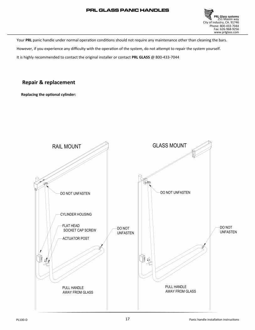
RAIL MOUNT GLASS MOUNT
DO NOT UNFASTEN DO NOT UNFASTEN
CYLINDER HOUSING
FLAT HEAD
SOCKET CAP SCREW
ACTUATOR POST
DO NOT
UNFASTEN
DO NOT
UNFASTEN
PULL HANDLE
AWAY FROM GLASS
PULL HANDLE
AWAY FROM GLASS
Your PRL panic handle under normal operation conditions should not require any maintenance other than cleaning the bars.
However, if you experience any difficulty with the operation of the system, do not attempt to repair the system yourself.
It is highly recommended to contact the original installer or contact PRL GLASS @ 800-433-7044
Repair & replacement
Replacing the optional cylinder:

PRL GLASS PANIC HANDLES
18
Panic handle installation instructions PL100-D
PRL Glass systems 251 Mason way
Phone: 800-433-7044 Fax: 626-968-9256 www.prlglass.com
City of industry, CA. 91746
ACTUATOR
POST
FLAT HEAD
SOCKET
CAP SCREW
ACTUATOR
POST
HANDLE
CYLINDER
CYLINDER
HOUSING
1.– Remove flat head socket cap screw
2.– Gently remove the handle away from the glass &
remove the actuator post from the handle

PRL GLASS PANIC HANDLES
19
Panic handle installation instructions PL100-D
PRL Glass systems 251 Mason way
Phone: 800-433-7044 Fax: 626-968-9256 www.prlglass.com
City of industry, CA. 91746
COLLAR
KEY SLOT
CYLINDER HOUSING
SET SCREW
COLLAR
WAVE
WASHERS
SET SCREWALLEN WRENCH
LOCK CYLINDER
1-1/8" O.D. X 1-1/4"
LENGHT
COLLAR
SET SCREW TAILPIECE
CYLINDER
HOUSING
Look into large hole in exterior housing.
The visible cam should appear
to line up with centerline of hole. If not,
turn cylinder in or out one turn
so line up is accomplished. tighten set screw
3.– Loosen the set screw holding the cylinder in place.
Use an allen wrench for this procedure
4.– Remove old cylinder & check to see if tailpiece matches new cylinder tailpiece. Also the length of the new cylinder must
be the same as the old one. A cylinder of any other length will require a new length collar. Fasten in new cylinder until it
stops inside the collar ring. Key slot should be on bottom of cylinder nearest the floor.
5.– to reassemble the unit, insert handle actuator post into panic handle & place it against the door
& attach to handle actuator post with the flat head socket cap screw.
PRL PANIC HANDLE OPTIONAL CYLINDER

PRL GLASS PANIC HANDLES
20
Panic handle installation instructions PL100-D
PRL Glass systems 251 Mason way
Phone: 800-433-7044 Fax: 626-968-9256 www.prlglass.com
City of industry, CA. 91746
MAINTENANCE OF STAINLESS STEEL FINISHES ON HANDLE
Polished #8 & brushed # 4 finishes on stainless steel (alloy 304) are one of the
most durable & easiest finishes to maintain.
PRL GLASS recommends a soft clean cloth & a foam type spray glass cleaner on
the soft cloth & rub the stainless steel part directionally parallel to its length.
This method applies to both polished & brushed finishes.
Note: Do not use circular motions when cleaning stainless steel, especially on
polished finishes, as doing so leaves fine polish lines on the surface. Do not use
steel wool to clean brushed stainless steel. Steel wool leaves small pieces of
wool in the brushed grooves. These pieces of wool will rust, thus the impression
that the stainless steel is rusting, which is impossible.

PRL GLASS PANIC HANDLES
21
Panic handle installation instructions PL100-D
PRL Glass systems 251 Mason way
Phone: 800-433-7044 Fax: 626-968-9256 www.prlglass.com
City of industry, CA. 91746
MAINTENANCE OF BRASS BRONZE FINISHES ON HANDLE
Polished & brushed finishes applied to brass & bronze alloys must be routinely maintained to retain the
desired appearance. The darkening or black spotting on the brass & bronze surfaces is simply oxidation tak-
ing place. If left untreated brass & bronze alloys will eventually turn entirely, but unevenly dark.
This dark oxidized state is the natural color of all copper alloys, which brass & bronze are included.
Maintenance of brass/bronze must be done on a routinely timely basis as needed. Depending on use &
abuse, location, weather conditions or exposure to marine air, will determine the frequency that the finish
will need attention.
Polished finishes (brass/bronze): polished brass is a simple process if done routinely.
PRL GLASS recommends “brasso metal polish” or equal which is applied much the same as car wax. Brass &
bronze are directionally polished @ the factory parallel to the length of the part. Apply the brass polish
with a soft clean cloth parallel to the length of the part with medium pressure. Allow the polish to dry &
buff with a soft clean cloth. Repeat if necessary.
Note: when polishing brass or bronze do not use a circular motion as it will leave a circular pattern in the
finish. PRL GLASS also suggests after re-polishing the brass or bronze, that a coat of “Harley’s pure carnuba
wax” be applied to help maintain the finish.
Brushed/Satin finishes (brass/bronze): Maintenance of brushed or satin brass/bronze finishes is done us-
ing an entirely different method than that of a polished finished. PRL GLASS recommends a “Scotch brite”
pad over the brass or bronze in the same direction as the existing finish (parallel to the length) will remove
the oxidation from the surface. Medium pressure in long easy strokes should be all that is necessary.
Note: do not use brass polish to clean brushed/satin finishes. The polish will load up the groves in the
brushed / satin finish making a simple clean job a lengthy one.

PRL GLASS PANIC HANDLES
22
Panic handle installation instructions PL100-D
PRL Glass systems 251 Mason way
Phone: 800-433-7044 Fax: 626-968-9256 www.prlglass.com
City of industry, CA. 91746
MAINTENANCE OF US10B STATUARY BRONZE ON HANDLE
The US10B is a process to age the brass/bronze surface to simulate the nature aging process.
The US10B will be specified in either oil rubbed or clear baked enamel to preserve the finish.
1.– Oil rubbed: after the aging process is complete, a hand applied lemon oil is rubbed onto the surface.
The oil rubbed process allows the brass to continue to darken. On a frequent basis lemon oil should be re-
applied with a soft clean cloth in the field. The frequency will determined when the metal surface appears
dull & dry.
2.– Clear baked enamel: after the aging process is complete a clear baked enamel is applied to the brass
surface to delay further darkening (aging). Clear baked enamel should be cleaned with a soft cotton cloth
& a spray type glass cleaner. Do not soak the brass finish.
Note: the clear baked enamel finish will delay aging but not eliminate the possibility. The baked enamel
finish is susceptible to abrasion & scratching. Clear baked enamel carries no warranty & it will eventually
have to be re-done.
PRL GLASS recommends that a professional brass maintenance company be hired to do any of the field
restorations.
We do not recommend any protective lacquering of brass & bronze door hardware. Lacquer wears off in
certain use areas leaving a non-uniform or spotty finish.
The areas most affected are those where the handles contact the metal. Furthermore, rings worn on the
fingers can cause the lacquer to be removed thus exposing the scratches of the lacquer.
However, protective lacquer will delay aging but not eliminate & will eventually have to be re-done.
If proper maintenance is followed, you will be able to elongate the time between re-finishing.
We recommend that a professional brass maintenance company be hired
to do any of the field restorations.


![[Panic Away] How to Control Panic Attacks](https://img.pdfslide.us/doc/110x75/55ae079a1a28abc1788b4687/panic-away-how-to-control-panic-attacks.jpg)


![[Panic Away] Menopause and Panic Attacks](https://img.pdfslide.us/doc/110x75/559482191a28abc67b8b4606/panic-away-menopause-and-panic-attacks.jpg)
![[Panic Away] Successfully Overcoming Panic Attacks](https://img.pdfslide.us/doc/110x75/559a31ed1a28ab96478b473a/panic-away-successfully-overcoming-panic-attacks.jpg)
![[Panic Away] How to Stop Panic Attack Symptoms](https://img.pdfslide.us/doc/110x75/55aa7d5d1a28ab016d8b48e7/panic-away-how-to-stop-panic-attack-symptoms.jpg)

![[Panic Away] How to Breathe Through Your Next Panic Attack](https://img.pdfslide.us/doc/110x75/55ae07b51a28abbb788b469f/panic-away-how-to-breathe-through-your-next-panic-attack.jpg)
![[Panic Away] Curing Panic Attacks in 4 Easy Steps](https://img.pdfslide.us/doc/110x75/55ae07d81a28abb5788b46a0/panic-away-curing-panic-attacks-in-4-easy-steps.jpg)
![[Panic Away] How to Quickly Cure Panic Attacks](https://img.pdfslide.us/doc/110x75/55aa7d721a28ab682b8b4597/panic-away-how-to-quickly-cure-panic-attacks.jpg)


![[Panic Away] Knowing How to Cure Panic Attacks](https://img.pdfslide.us/doc/110x75/55ae07b21a28abbb788b469c/panic-away-knowing-how-to-cure-panic-attacks.jpg)
![[Panic Away] How to Avoid Panic Attacks](https://img.pdfslide.us/doc/110x75/55ae07841a28abc8788b4660/panic-away-how-to-avoid-panic-attacks.jpg)
![[Panic Away] Getting a Grip On Your Panic Disorder](https://img.pdfslide.us/doc/110x75/5591889d1a28abbb4c8b46cd/panic-away-getting-a-grip-on-your-panic-disorder.jpg)
![[Panic Away] Panic Is No Laughing Matter](https://img.pdfslide.us/doc/110x75/55ae087f1a28abab788b476d/panic-away-panic-is-no-laughing-matter.jpg)