Embed Size (px)
Citation preview
PL & RL SeriesHydraulic Lift Tables
Installation, Operationand Service Manual
Model Number ___________________Serial # _______ __________________Date Placed in Service _____________
IMPORTANT: READ CAREFULLY
BEFORE INSTALLING OR OPERATING LIFT
Part orders are subject to a $50 minimum charge.
JUNE 2016
Page 2 — PRESTO OWNER’S MANUAL: PL SERIES
This manual was current at the time of printing. To obtain the latest, most updated version, please contact Presto Lifts Customer Service Department or go to our website: www.PrestoLifts.com -- you will find a complete list of current owner’s manuals to print.
PRESTO OWNER’S MANUAL: PL SERIES — Page 3
C O N T E N T S
SECTION 1: Introduction .................................................................................................. 4
Responsibility of Owners and Users ............................................................................ 5
Safety Alert Symbols and Signal Words ...................................................................... 6
SECTION 2: Safety ............................................................................................................ 7
SECTION 3: Unpacking and Assembly ............................................................................. 8
A. Inspection ............................................................................................................... 8
SECTION 4: Operation ...................................................................................................... 8
A. Set-Up Procedure ................................................................................................... 8
B. Operating Procedure for Hydraulic Tables .............................................................. 8
SECTION 5: Servicing ....................................................................................................... 8
A. Servicing Instructions ............................................................................................. 8
If table does not rise to full height ......................................................................... 8
If table does not load, or creeps down ................................................................... 8
To remove cylinder from table ............................................................................... 9
B. Periodic Maintenance ............................................................................................ 9
C. Operator Safety ....................................................................................................... 9
ORDERING REPLACEMENT PARTS .......................................................................... 14
RESTOCKING POLICY ................................................................................................. 15
RETURN GOODS AUTHORIZATION (RGA) PROCEDURES .................................. 16
WARRANTY ................................................................................................................... 17
LIST OF FIGURES:
Figure 1 Foot Pump Assembly .................................................................................. 9
Figure 2 Cylinder Seal Kit ........................................................................................ 10
Figure 3 Floor Position Detail (models sold prior to July 2005) ....................................... 11
Figure 4 Floor Position Detail (models sold July 2005 & after) ....................................... 12
Table 1: Hydraulic Oil Specifications ....................................................................... 14
Figure 5 Labels and Locations ................................................................................... 13
Page 4 — PRESTO OWNER’S MANUAL: PL SERIES
S E C T I O N 1
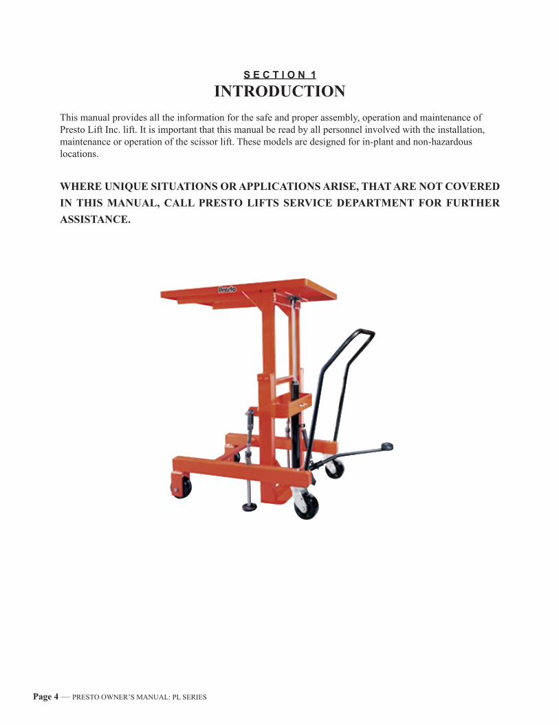
INTRODUCTIONThis manual provides all the information for the safe and proper assembly, operation and maintenance of Presto Lift Inc. lift. It is important that this manual be read by all personnel involved with the installation, maintenance or operation of the scissor lift. These models are designed for in-plant and non-hazardous locations.
WHERE UNIQUE SITUATIONS OR APPLICATIONS ARISE, THAT ARE NOT COVERED IN THIS MANUAL, CALL PRESTO LIFTS SERVICE DEPARTMENT FOR FURTHER ASSISTANCE.
PRESTO OWNER’S MANUAL: PL SERIES — Page 5
Responsibility of Owners and Users
Inspection and MaintenanceThe device shall be inspected and maintained in proper working order in accordance with Presto’s owner’s manual.
Removal from ServiceAny device not in safe operating condition such as, but not limited to, excessive leakage, missing rollers, pins, or fasteners, any bent or cracked structural members, cut or frayed electric, hydraulic, or pneumatic lines, damaged or malfunctioning controls or safety devices, etc. shall be removed from service until it is repaired to the original manufacturer’s standards.
RepairsAll repairs shall be made by qualified personnel in conformance with Presto’s instructions.
OperatorsOnly trained personnel and authorized personnel shall be permitted to operate PowerStak.
Before OperationBefore using the device, the operator shall have:• Read and/or had explained, and understood, the manufacturer’s operating instructions and safety
rules.• Inspected the device for proper operation and condition. Any suspect item shall be carefully ex-
amined and a determination made by a qualified person as to whether it constitutes a hazard. All items not in conformance with Presto’s specification shall be corrected before further use of the PowerStak.
During OperationThe device shall only be used in accordance with this owner’s manual.• Do not overload.• Ensure that all safety devices are operational and in place.
Modifications or AlterationsModifications or alterations to any Presto industrial positioning equipment shall be made only with written permission from Presto.
Page 6 — PRESTO OWNER’S MANUAL: PL SERIES
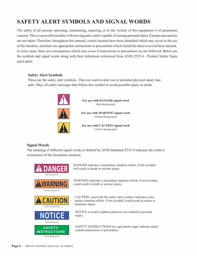
SAFETY ALERT SYMBOLS AND SIGNAL WORDSThe safety of all persons operating, maintaining, repairing, or in the vicinity of this equipment is of paramount concern. This is a powerful machine with moving parts, and is capable of causing personal injury if proper precautions are not taken. Therefore, throughout this manual, certain hazards have been identified which may occur in the use of the machine, and there are appropriate instructions or precautions which should be taken to avoid these hazards. In some cases, there are consequences which may occur if instructions or precautions are not followed. Below are the symbols and signal words along with their definitions referenced from ANSI Z535.4 - Product Safety Signs and Labels.
Safety Alert SymbolsThese are the safety alert symbols.. They are used to alert you to potential physical injury haz-ards. Obey all safety messages that follow this symbol to avoid possible injury or death.
For use with DANGER signal word(Red Background)
For use with WARNING signal word(Orange Background)
For use with CAUTION signal word(Yellow Background)
Signal WordsThe meaning of different signal words as defined by ANSI Standard Z535.4 indicates the relative seriousness of the hazardous situation.
DANGER indicates a hazardous situation which, if not avoided, will result in death or serious injury.
WARNING indicates a hazardous situation which, if not avoided, could result in death or serious injury.
CAUTION, used with the safety alert symbol, indicates a haz-ardous situation which, if not avoided, could result in minor or moderate injury.
NOTICE is used to address practices not related to personal injury.
(Red Background)
(Orange Background)
(Yellow Background)
(Blue Background)
SAFETYINSTRUCTIONS
SAFETY INSTRUCTIONS (or equivalent) signs indicate safety-related instructions or procedures.
(Green Background)
PRESTO OWNER’S MANUAL: PL SERIES — Page 7
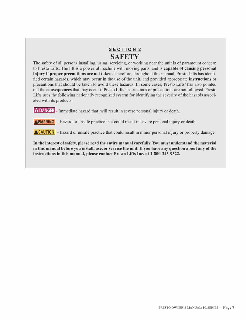
S E C T I O N 2
SAFETYThe safety of all persons installing, using, servicing, or working near the unit is of paramount concern to Presto Lifts. The lift is a powerful machine with moving parts, and is capable of causing personal injury if proper precautions are not taken. Therefore, throughout this manual, Presto Lifts has identi-fied certain hazards, which may occur in the use of the unit, and provided appropriate instructions or precautions that should be taken to avoid these hazards. In some cases, Presto Lifts’ has also pointed out the consequences that may occur if Presto Lifts’ instructions or precautions are not followed. Presto Lifts uses the following nationally recognized system for identifying the severity of the hazards associ-ated with its products:
DANGER! – Immediate hazard that will result in severe personal injury or death.
WARNING – Hazard or unsafe practice that could result in severe personal injury or death.
CAUTION! – hazard or unsafe practice that could result in minor personal injury or property damage.
In the interest of safety, please read the entire manual carefully. You must understand the material in this manual before you install, use, or service the unit. If you have any question about any of the instructions in this manual, please contact Presto Lifts Inc. at 1-800-343-9322.
Page 8 — PRESTO OWNER’S MANUAL: PL SERIES
S E C T I O N 3
UNPACKINGAND ASSEMBLY
A. INSPECTIONUpon receipt of the PL Lift, inspect the equipment completely to determine if there is any shipment damage and that the lift is complete. Do not use the lift if there appears to be any damage.
S E C T I O N 4
OPERATIONA. SET-UP PROCEDUREEach Hydraulic Table has been thoroughly inspected and tested prior to shipment. Due to possible damage in transit the following procedure must be performed before the equipment is used.1. Remove all protective covering making certain
that nothing is jammed or fallen into the moving parts of the table.
2. Inspect the Table for damage in shipment. Be sure to notify the trucking firm immediately if there is any damage.
3. All Hydraulic Tables are equipped with a hand operated floor lock.
4. For shipment, the foot pedal is wired to the unit. Before using the table this pedal should be in-stalled into the foot pump lever.
B. OPERATING PROCEDURE FOR HYDRAU-LIC TABLESThe following instructions apply to the hydraulic table. Carefully read and understand the procedures before operating the equipment:1. Maximum table capacity for the Hydraulic Table
is 2000 lbs. (Rubber wheels 1000 lbs. capacity.)2. Before loading or unloading table, make sure
the hand operated floor lock is securely locked against the floor. This requires you to pull up upon the floor handle. The floor lock is released by pushing the handle down.
3. Always place loads near the center of the table. When transferring loads to the table platform always slide, rather than drop, onto the raised table.
4. Pump the pedal on the cylinder to raise the table.
Depress the release pedal to lower the table.5. Keep feet out of the carriage unit; keep hands out
of the roller path.6. Always lower table (especially when loaded) to
its lowest position before moving the machinery any distance.
7. Keep hands clear from under the table when load-ing and unloading.
S E C T I O N 5
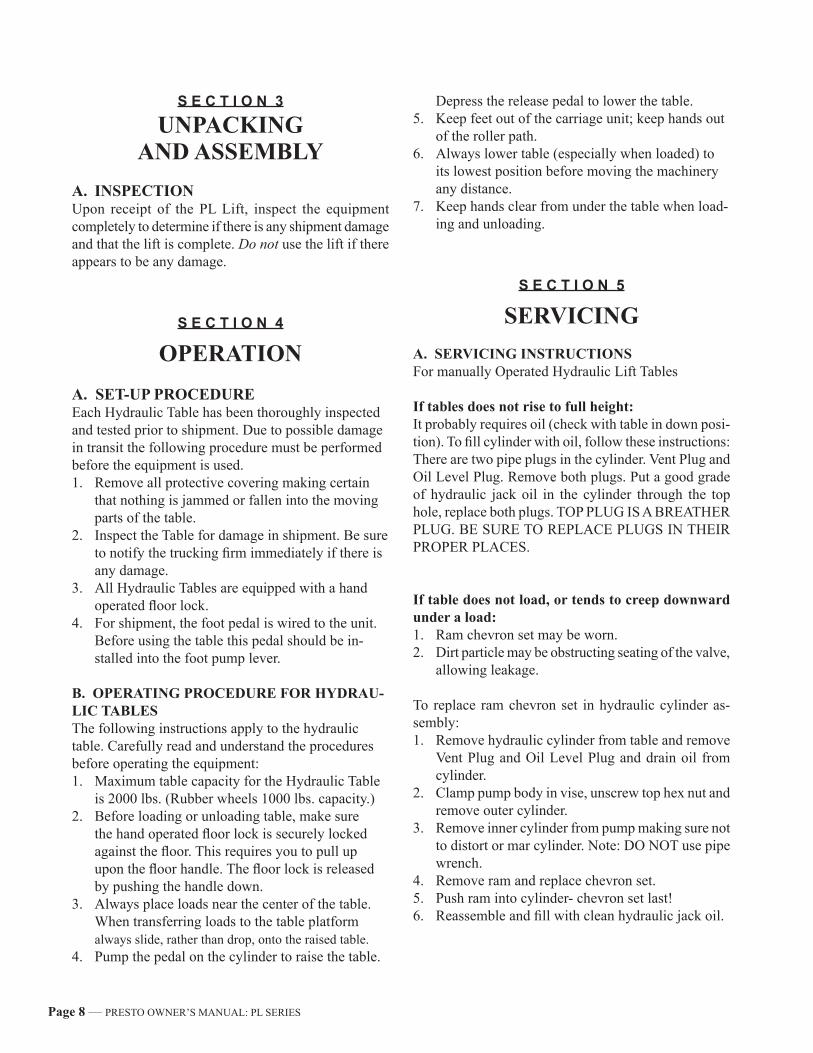
SERVICINGA. SERVICING INSTRUCTIONSFor manually Operated Hydraulic Lift Tables
If tables does not rise to full height:It probably requires oil (check with table in down posi-tion). To fill cylinder with oil, follow these instructions: There are two pipe plugs in the cylinder. Vent Plug and Oil Level Plug. Remove both plugs. Put a good grade of hydraulic jack oil in the cylinder through the top hole, replace both plugs. TOP PLUG IS A BREATHER PLUG. BE SURE TO REPLACE PLUGS IN THEIR PROPER PLACES.
If table does not load, or tends to creep downward under a load:1. Ram chevron set may be worn.2. Dirt particle may be obstructing seating of the valve,
allowing leakage.
To replace ram chevron set in hydraulic cylinder as-sembly:1. Remove hydraulic cylinder from table and remove
Vent Plug and Oil Level Plug and drain oil from cylinder.
2. Clamp pump body in vise, unscrew top hex nut and remove outer cylinder.
3. Remove inner cylinder from pump making sure not to distort or mar cylinder. Note: DO NOT use pipe wrench.
4. Remove ram and replace chevron set.5. Push ram into cylinder- chevron set last!6. Reassemble and fill with clean hydraulic jack oil.
PRESTO OWNER’S MANUAL: PL SERIES — Page 9
If dirt particle is obstructing seating of the valve:Open release valve by pressing down on the release pedal. At the same time, pump foot lever three or four strokes. Do this three or four time. Then place some weight on the platform and pump foot lever until plat-form reaches its full height. Now, lower table six inches to a foot at a time. This will dislodge dirt and table will work properly.
To remove cylinder from table:1. Pump table to above 12-inch height and then
prop platform up to keep it in raised position.2. Step on release pedal and push ram down by
hand until it reaches its lowest point.3. Take out four hex bolts which screw cylinder
into place and slide cylinder backward towards the casters of the table and the cylinder can be easily removed.
B. PERIODIC MAINTENANCE
INSPECTION POINTS1. Check floor lock for positive locking operation-
daily.2. Check all nuts and bolts for proper tightness-
monthly.3. Check uprights for abrasives, dirt and oil caked
contaminants- daily.4. Inspect all decals- daily.5. Keep all parts not requiring lubrication clean of
lubricants. Pay particular attention to the outside of uprights and platform where personnel injury could result from slippery lubricant- daily.
6. Check structural frames for damage and cracked welds- daily.
7. Clean and inspect guides and guide wheels- weekly.
8. Clean and inspect all welds- weekly.9. Clean and inspect lifting chains- monthly.10. Lubricate chain with a rust inhibitive lubricant-
weekly.11. Adjust chain tension- tighten lock nut- weekly.12. Clean and inspect for wear and damage, support-
ing wheels and casters- weekly.13. Tighten all hold down bolts- weekly.14. Lubricate wheel axles, king pins and bearings-
weekly.15. Test floor lock for holding ability- weekly.16. Check for hydraulic leaks- monthly.17. Check hydraulic fluid with the platform fully
lowered. Remove screw B fig. 1 Oil should be just below this level. If oil is needed use Conoco Super Hydraulic 32. DO NOT USE BRAKE FLUID. The hydraulic oil does not have to be changed unless it is unusually dirty (very dark in color) or if water is introduced due to condensa-tion-weekly.
C. OPERATOR SAFETY REMINDERSPresto Lifts designs and builds equipment to provide reliable, long service. The National Safety Council reminds us that most accidents are caused by the fail-ure to follow simple and fundamental safety rules and precautions. A careful operator is the best insurance against an accident. Therefore, proper usage of the table is mandatory. Modifications from the original design are strictly forbidden without permission from Presto Lifts.
CAUTION:A competent and responsible person familiar
with procedures as outlined in this manual should perform inspection.
F I G U R E 1: FOOT PUMP ASSEMBLY
For models sold prior to July 2005
Page 10 — PRESTO OWNER’S MANUAL: PL SERIES
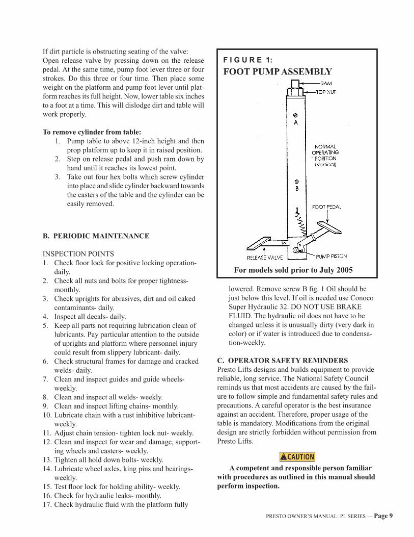
F I G U R E 2: CYLINDER SEAL KIT
NOTE: All part numbers are for models sold prior to July 2005. For machines manufactured in July 2005 and newer, contact the Presto Parts Department with the model and serial number of your machine so the correct part numbers can be quoted.

PRESTO OWNER’S MANUAL: PL SERIES — Page 11
F I G U R E 3: FLOOR POSITION DETAIL AND PL SERIES PARTS LIST
Item Part # Description Qty.1 & 2 C101E Stem Caster 13 M400-36 36" rise Cylinder Assy. 13 M400-48 48" rise Cylinder Assy. 13 M400-52 60" rise Cylinder Assy. 14 0462-04 Camrol Bearing 4 5 PSL29 Collar 2 6 PSL23A Locking Lever 27 PSL28 Pin Assy. 28 PSL25A Brake Lever 29 NO180 Locking Nut 210 PSL22 Brake Stud 211 PSL24 Rubber Cushion 212 PSL26 Spring 213 PSL21C Pad Holder 214 M437 Lock Pad 215 0491-03 Lock Handle 116 0415 Lift Stop 217 N0901 Hex Hd. Bolt 418 C103 Axle 219 C102PH Wheel Assy. 2
* See the individual cylinder assembly breakdown for associated parts.
• Wheel Assembly consists of wheel, bearing and spanner.
NOTE: All part numbers are for models sold prior to July 2005. For machines manufactured in July 2005 and newer, contact the Presto Parts Department with the model and serial number of your machine so the correct part numbers can be quoted.
Page 12 — PRESTO OWNER’S MANUAL: PL SERIES
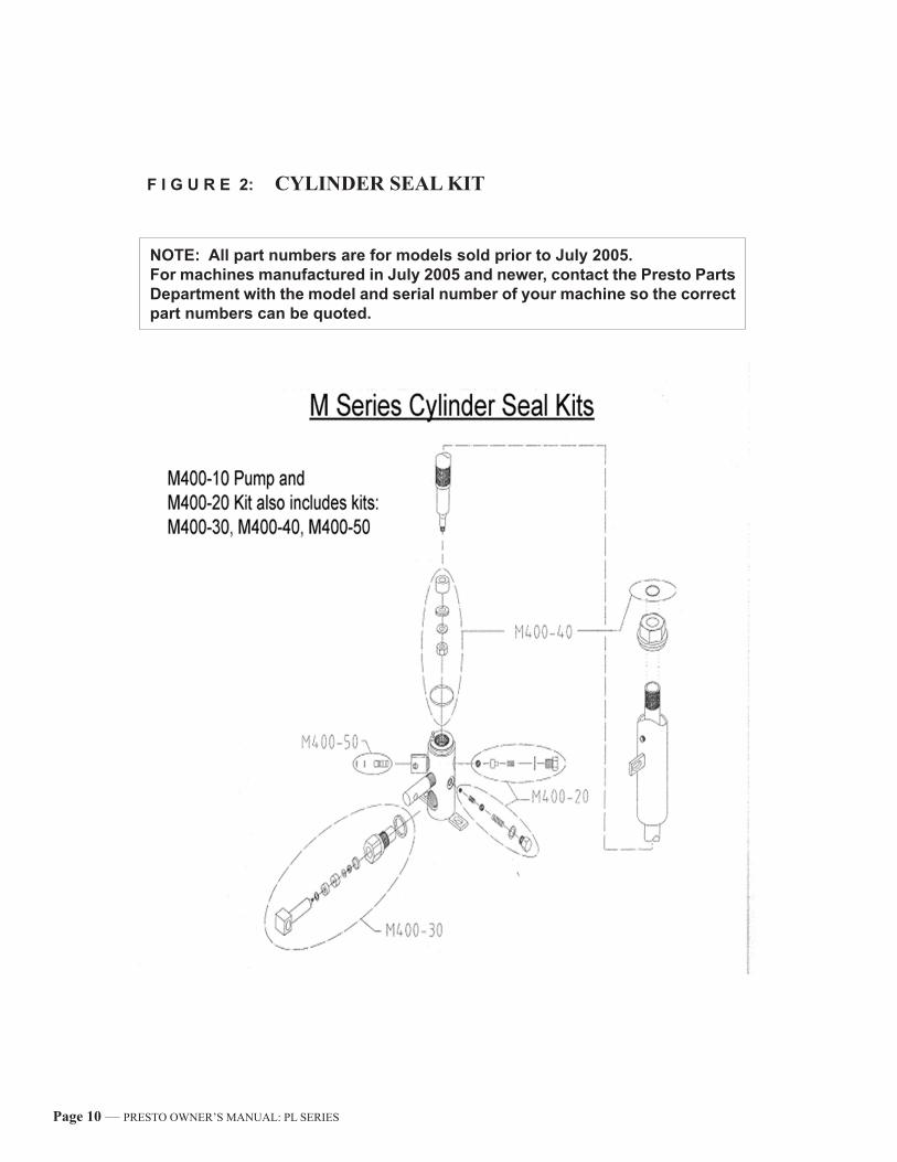
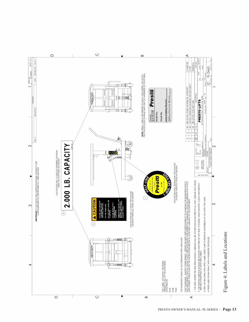
F I G U R E 4: FLOOR POSITION DETAIL AND PL SERIES PARTS LIST
NOTE: For models sold July 2005 and after.
Please contact Presto Parts Department.
Item Description Qty.1 Swivel Caster 219 Rigid Caster 23 36" rise Cylinder Assy 1 3 48" rise Cylinder Assy 1 3 60" rise Cylinder Assy 114 Floor Lock 115 Floor Lock Pad 1 Pump/Cyl Seal Kit
• Wheel Assembly consists of wheel, bearing and spanner.
PRESTO OWNER’S MANUAL: PL SERIES — Page 13
LOC
ATE
ITEM
NO
. C16
5ST-
20 C
ENTE
RED
ON
BO
THEN
DS
OF
PLA
TFO
RM A
S SH
OW
N
3
LOC
ATE
ITEM
NO
. C17
8 IN
TW
O P
LAC
ESO
N B
OTH
VER
TICA
L PO
STS
AS
SHO
WN
2
LOC
ATE
ITEM
NO
. 300
0041
4 IN
TW
O P
LAC
ESO
N B
OTH
VER
TICA
L PO
STS
AS
SHO
WN
1N
OTE
: SER
IAL
LABE
LS A
RE P
RIN
TED
TO
EA
CH
JOB
ORD
ER. L
OC
ATE
IN
TWO
PLA
CES
(ON
E O
N B
ASE
AN
D O
NE
ON
UN
DER
SID
E O
F PL
ATF
ORM
)
1. T
HE A
REA
WHE
RE T
HE N
EW R
EPLA
CEM
ENT
LABE
LIN
G W
ILL
BE A
PPLI
ED S
HOUL
D B
E FR
EE O
F A
LL D
IRT,
GRE
ASE
AN
D G
RIM
E.
2. T
HE P
AIN
TED
SUR
FAC
E SH
OUL
D B
E SM
OO
TH A
ND
FRE
E O
F A
NY
RUST
. IF
RUST
ED, S
AN
D S
MO
OTH
, CLE
AN
AN
D R
EPA
INT
B
EFO
RE A
TTEM
PTIN
G T
O A
FFIX
NEW
LA
BELS
.
3. P
EEL
OFF
BA
CKI
NG
AN
D A
PPLY
LA
BEL
USIN
G C
ARE
TO
REM
OV
E A
IR B
UBBL
ES A
S YO
U A
PPLY
THE
LA
BEL.
4. P
RESS
LA
BEL
DO
WN
FIR
MLY
WITH
A S
QUE
EGEE
OR
ROLL
ER.
THIS
EQ
UIPM
ENT
IS B
UILT
IN A
CC
ORD
AN
CE
WITH
AN
SI M
H29.
THA
T ST
AN
DA
RD,
AM
ON
G O
THER
THI
NG
S, D
EFIN
ES T
HE E
ND
USE
R'S
RESP
ON
SIBI
LITY
TO
MA
INTA
IN T
HE E
QUI
PMEN
T W
HIC
H
INC
LUD
ES S
EEIN
G T
HAT
ALL
NA
ME
PLA
TES,
PRE
CA
UTIO
NA
RY A
ND
INST
RUC
TAL
MA
RKIN
GS,
AN
D/O
R LA
BELI
NG
IS IN
PLA
CE
AN
D L
EGIB
LE. P
LEA
SE F
OLL
OW
THE
INST
RUC
TION
S BE
LOW
TO
AFF
IX N
EW L
ABE
LIN
G T
O T
HE E
QUI
PMEN
T.
THIS
LA
BEL
LO
CA
TION
DRA
WIN
GA
PPLI
ES T
O A
LL O
F TH
E M
AC
HIN
ESLI
STED
BEL
OW
: PL
36 PL
48 PL
60
IMPO
RTA
NT:
IF Y
OU
HAV
E A
NY
QUE
STIO
NS
PLEA
SE C
ON
TAC
T O
URC
USTO
MER
SER
VIC
E D
EPA
RTM
ENT
AT
1-80
0-34
3-93
22
ITEM
N
O.
QTY
.U/
MD
ESC
RIPT
ION
PART
NO
.
32
EABK
-LD
DC
L 9.
00X1
.50
2000
LB.
CA
PAC
ITYC
165S
T-20
22
EALD
DC
L 3.
00X5
.00
CA
UTIO
N: D
O N
OT
USE
IFC
178
12
EABK
-LD
DC
L 3.
00 H
ELP
LIN
E30
0004
14
REV
ISIO
NS
REV
.
D
ESC
RIPT
ION
DA
TERE
VIS
ED B
YEC
O #
CD B A
43
21
D C B A
31
24
SHEE
T 1 O
F 1
DW
G N
O PL D
IAG
50 C
omm
erce
Way
Nor
ton
MA
027
66
STATUS:CAD Area WIP
3RD
AN
GLE
PRO
JEC
TION
-
16
- L
B
PL D
IAG
REV
DW
G.
NO
.C SI
ZETIT
LE:
FRA
CTIO
NS
1
/.X
XX
.005
.XX
.01
AN
GLE
S:
.5
USE
OF
PRO
PRIE
TARY
INFO
RMA
TION
LIM
ITED
TO
WRI
TTEN
AG
REEM
ENT
SCA
LEW
TRE
FERE
NC
EC
AG
E C
OD
E06
3Z8
UNLE
SS O
THER
WIS
ESP
ECIF
IED
.D
IMEN
SIO
NS
ARE
ININ
CHE
S
SHEE
T 1 O
F 1
DR
CK
1:1
0
PR
ES
TO
LIF
TS
08/2
4/15
DA
TE
DA
TE
CFM
MO
DEL
-PR
OJE
CT:
v.14
Figu
re 4
: Lab
els a
nd L
ocat
ions
Page 14 — PRESTO OWNER’S MANUAL: PL SERIES
Table 1 – Hydraulic Oil Specifications
If the lift will be used at normal ambient temperatures, Presto Lifts supplies the unit with Conoco Super Hydraulic 32 oil. This may be replaced by any other good quality oil with 150 SSU at 100° F and rust and oxidation inhibitors and anti-wear properties. If the lift will be used at ambient temperatures below 0°F, use aircraft hydraulic oil. Use Type 15 aircraft hydraulic oil.
The following are equivalent to CONOCO SUPER HYDRAULIC 32:
TYPE MANUFACTURER
AW32 .............................CITGODTE 24 ..........................EXXON/MOBILNUTO H32 ....................EXXON/MOBILAMOCO AW32 ..............CHEVRON (AMOCO CO.)
CAUTION! It is very important to keep the hydraulic oil free of dirt, dust, metal chips, water, and other contamination. Most of the problems with hydraulic systems are caused by contamination in the oil.
Ordering Replacement PartsPresto Lifts has carefully chosen the components in your unit to be the best available for the purpose. Replacement parts should be identical to the original equipment. Presto Lifts will not be responsible for equipment failures resulting from the use of incorrect replacement parts or from unauthorized modifications to the unit. Presto Lifts can supply all replacement parts for your lift. With your order, please include the model number and the serial number of the unit. You can find these numbers on the name plate. This plate is located within the scissors mechanism.To order replacement parts, please call the Presto Parts Department. Parts are shipped subject to the following terms:
• FOB factory• Returns only with the approval of our parts department.• Credit cards preferred (except parts covered by warranty).• Freight collect for truck (except parts covered by warranty).• Freight – prepaid and invoice for small parcel shipments (except parts covered by warranty).• The warranty for repair parts is 30 days from date of shipment.
Parts replaced under warranty are on a “charge-credit” basis. We will invoice you when we ship the replacement part, then credit you when you return the worn or damaged part, and we verify that it is covered by our warranty. Labor is not covered under warranty for Parts orders.
Presto Parts Department50 Commerce WayNorton, MA 02766
Telephone: 800-343-9322FAX: 888-788-6496
Email: [email protected]
PRESTO OWNER’S MANUAL: PL SERIES — Page 15
PARTSStandard parts may be returned with a 20% restocking fee. Modified or custom-engineered parts are not returnable. Unfortunately, due to potentially concealed damage, all sales of electrical assemblies are final.
QUALITY ISSUESShould you feel there is a quality problem, please contact the seller to ask questions and gather information on how to rectify the issue. Presto Lift Inc. reserves the right to determine potential credits, as a result of factory defects, based on its inspection of the merchandise.
GENERALAll products shipped from our factory have passed Quality Assurance inspection and testing. The carrier of choice has signed for, and accepted the product in new working condition. The customer should inspect to ensure it is not received damaged, has no concealed damage or is not incomplete. Parts orders are determined to be complete based upon Presto Lift, Inc. inspection sheets and carrier shipping weights.
Page 16 — PRESTO OWNER’S MANUAL: PL SERIES
RETURN GOODS AUTHORIZATION POLICY
Presto Lifts provides the Return Goods Authorization (RGA) Policy, for specific models, as a courtesy to our distributors in the event they do not receive what they ordered. If a customer wishes to return a Presto Lifts product, please contact the Customer Service Department and request an RGA number. This request must be made on or before the fifteenth calendar day following the date of Presto Lifts’ invoice for the merchandise. Not all units are returnable. Quantity orders and special designs cannot be returned under any circumstances. Presto Cus-tomer Service reserves the right for final judgment on all product returns.
The RGA number must appear on the outside of any packaging material for a return to be ac-cepted and processed by Presto Lifts. Customers shipping returns from the Continental US, Canada, or Mexico have thirty (30) days from date of RGA issue to have the product arrive at Presto Lifts’ facility. All merchandise must arrive Free on Board at Presto Lifts’ facility or the shipment will be refused and returned to the sender. All credits are issued less restocking and refurbishing charges, regardless if the merchandise was damaged in transit.
Return addresses: please refer to your RMA for the address to which your product should be returned.
Presto Lift Inc.715 Highway 77
Manila, Arkansas 72442
Telephone: 800-343-9322Fax: 888-788-6496

PRESTO OWNER’S MANUAL: PL SERIES — Page 17
Presto Lifts Limited Warranty PolicyPresto Lifts warrants all of its products against defects in the welded structural frame and, if applicable, scissor legs from faulty material and workmanship for a period of five (5) years from the date of invoice.
All other components have a limited warranty against defects in faulty material and workmanship for a two (2) year period from the date of invoice date of invoice and 30 day limited warranty on labor. Please note that prior authorization from Presto Lifts is required on all warranty work.
There are no implied warranties of any kind, more specifically, there are no warranties of merchantability or fitness for any particular purpose. Presto Lifts' sole warranty shall be as set forth in this limited warranty.
Presto Lifts will elect to repair or replace a defective component without charge, if any components should become defective within the limited warranty period. Proof of purchase is required for warranty. The charge for shipping the defective component is the responsibility of the buyer and must be accompanied with an RGA number. The shipping charge to return the component to the buyer is the responsibility of Presto Lifts, Inc.
This limited warranty does not cover labor expense for removal or reinstallation of components after thirty days. This limited warranty shall not cover, among other things: damages resulting from foreign matter or water, failure to provide reasonable and necessary maintenance, and if applicable, use of product while charger is plugged into an AC outlet, or failure to follow operating instructions. The limited warranty is not valid for damage resulting from negligence, accident, unreasonable use, abuse or misuse, exceeding data plate capaci-ties or altering the product without Presto Lifts authorization.
Presto Lifts expressly disclaims and excludes any liability for consequential, incidental, indirect or punitive damages or financial loss to people or property resulting from any breach of warranty or the operation or failure of this product.
Presto Lifts makes no representation that this product complies with local, state, or federal safety/product standards codes. Should this product fail to comply in any way with those codes, it shall not be considered a defect of materials or workmanship. Presto Lifts shall not be held liable for any damages resulting from non-compliance. It is the dealer's responsibility to exercise this limited warranty. This limited warranty is provided to the original purchaser (defined as the original end user) and is nontransferable. This constitutes the complete and final agreement involving Presto Lifts and limited warranty obligations for products.
Page 18 — PRESTO OWNER’S MANUAL: PL SERIES
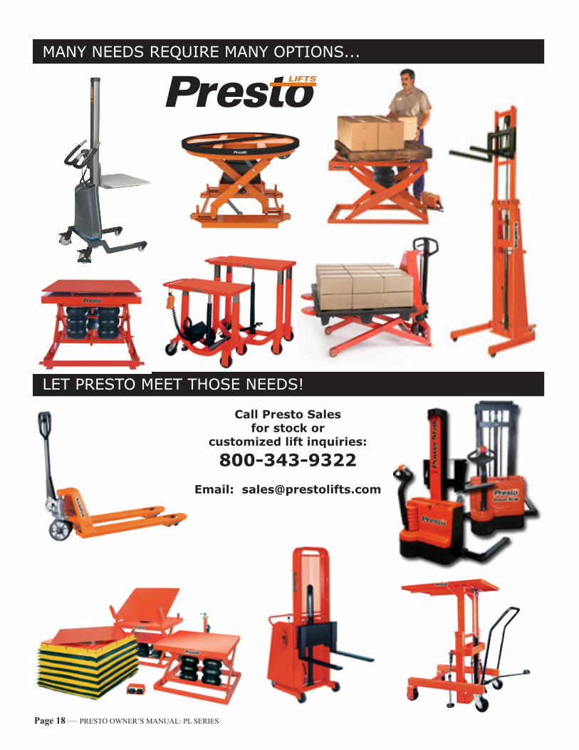
LET PRESTO MEET THOSE NEEDS!
MANY NEEDS REQUIRE MANY OPTIONS...
Call Presto Sales for stock or
customized lift inquiries:
800-343-9322Email: [email protected]