Embed Size (px)
DESCRIPTION
YHUJM
Citation preview
Time : 3 Hours
PLEASE WRITE YOUR ROLL NO. AT THE SPACE PROVIDED ON EACH PAGE IMMEDIATELY AFTER RECEIVING THE QUESTION PAPER.
NOTE: There are 9 questions in all.
Question 1 is compulsory and carries 20 marks. Answer to Q.1 must be written in the space provided for it in the answer book supplied and nowhere else.
The answer sheet for the Q.1 will be collected by the invigilator after 45 minutes of the commencement of the examination.
Out of the remaining EIGHT Questions answer any FIVE Questions. Each question carries 16 marks.
Any required data not explicitly given, may be suitable assumed and stated.
Q.1 Choose the correct or the best alternative in the following:
a. The number of point to point links required in a fully connected network for the 50 entities is
(A) 1250 (B) 1225
(C) 2500 (D) 50
Ans : C
b. Telephone companies normally provide a voltage of _________ to power telephones.
(A) +24 volts DC (B) -24 volts DC
(C) +48 volts DC (D) -48 volts DC
Ans : D
c. The situation when both transmitter and receiver have to work in tandem is referred to as
(A) Parallel (B) serial
(C) synchronous (D) asynchronous
Ans : C
d. Common Channel signaling ______________________
(A) Uses the speech or data path for signaling
(B) Does not use the speech or data path for signaling
(C) Needs no additional transmission facilities.
(D) Finds it difficult to handle signaling during speech
Ans : C
e. A large numbers of computers in a wide geographical area can be efficiently connected using
(A) Twisted pair lines
(B) Coaxial cables
(C) Communication satellites
(D) all of the above
Ans : D
f. Which transmission mode is used for data communication along telephone line?
(A) Parallel (B) serial
(C) Synchronous (D) asynchronous
Ans : B
g. A sample rate of ________ is required for a good quality representation of telephone conversation.
(A) 4500 times per second
(B) 700 integer sample points per minute
(C) 50 times per second per mile of distance travelled
(D) 8000 times per second
Ans : C
h. The ______ is a circuit-switched network, while the _______ is a packet-switched network.
(A) Telephone, ATM (B) SONET and FDDI
(C) Satellite, Telephone (D)FDDI and SONET
Ans : A
i. A master group consists of
(A) 12 voice channels (B) 24 voice channels
(C) 60voice channels (D) 300 voice channels
Ans : D
j. Erlang is used to
(A) Measure busy period (B) Give total busy period in minutes
(C) Measure average call rate (D) Indicate total call period
Ans : A
Q.2.a. With neat diagrams explain the configuration of a step-by-step switching system.
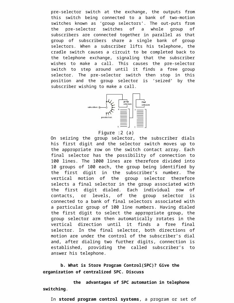
ANS: The schematic diagram for such an exchange is given in Fig. Each subscriber is connected to a single rotary pre-selector switch at the exchange, the outputs from this switch being connected to a bank of two-motion switches known as ‘group selectors’. The out-puts from the pre-selector switches of a whole group of subscribers are connected together in parallel as that group of subscribers share a single bank of group selectors. When a subscriber lifts his telephone, the cradle switch causes a circuit to be completed back to the telephone exchange, signaling that the subscriber wishes to make a call. This causes the pre-selector switch to step around until it finds a free group selector. The pre-selector switch then stop in this position and the group selector is ‘seized’ by the subscriber wishing to make a call.
Figure :2 (a)On seizing the group selector, the subscriber dials his first digit and the selector switch moves up to the appropriate row on the switch contact array. Each final selector has the possibility of connection to 100 lines. The 1000 lines are therefore divided into 10 groups of 100 each, the group being identified by the first digit in the subscriber’s number. The vertical motion of the group selector therefore selects a final selector in the group associated with the first digit dialed. Each individual row of contacts, or levels, of the group selector is connected to a bank of final selectors associated with a particular group of 100 line numbers. Having dialed the first digit to select the appropriate group, the group selector arm then automatically rotates in the vertical direction until it finds a free final selector. In the final selector, both directions of motion are under the control of the subscriber’s dial and, after dialing two further digits, connection is established, providing the called subscriber’s to answer his telephone.
b. What is Store Program Control(SPC)? Give the organization of centralized SPC. Discuss
the advantages of SPC automation in telephone switching.
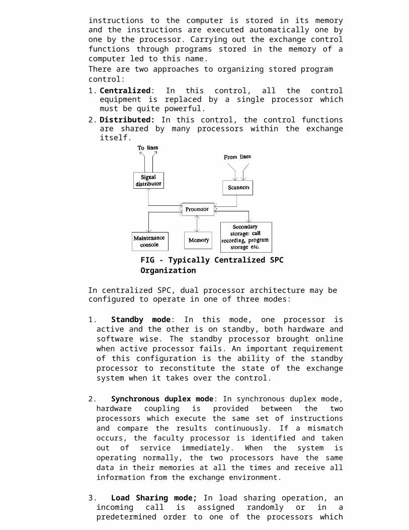
In stored program control systems, a program or set of instructions to the computer is stored in its memory and the instructions are executed automatically one by one by the processor. Carrying out the exchange control functions through programs stored in the memory of a computer led to this name.There are two approaches to organizing stored program control:1. Centralized: In this control, all the control equipment is replaced by a single
processor which must be quite powerful.
2. Distributed: In this control, the control functions are shared by many processors within the exchange itself.
FIG - Typically Centralized SPC Organization
In centralized SPC, dual processor architecture may be configured to operate in one of three modes:
1. Standby mode: In this mode, one processor is active and the other is on standby, both hardware and software wise. The standby processor brought online when active processor fails. An important requirement of this configuration is the ability of the standby processor to reconstitute the state of the exchange system when it takes over the control.
2. Synchronous duplex mode: In synchronous duplex mode, hardware coupling is provided between the two processors which execute the same set of instructions and compare the results continuously. If a mismatch occurs, the faculty processor is identified and taken out of service immediately. When the system is operating normally, the two processors have the same data in their memories at all the times and receive all information from the exchange environment.
3. Load Sharing mode; In load sharing operation, an incoming call is assigned randomly or in a predetermined order to one of the processors which then handles the call right through completion. Thus both the processors are active simultaneously and share the load and the resources dynamically.
Advantages of SPC:(i) Easy to control(ii) Easy to maintain (iii) Flexible (iv) Wide range of services can be provided to customers.
Q.3.a.What is time division switching? (4)
Time Division Switching: A switching element can be shared by number of simultaneously active speech circuits. This is the principle of time division switching. Obviously, with the way the switching elements are shared in time division switching, much greater savings can be achieved in the number of switching elements when compared to multistage space division switching.Basic Time Division Switching: The functional blocks of a memory based time division switching switch is shown in Fig. and its equivalent circuit in Fig. In this organisation, the data coming in through the inlets are written into the data memory and later read out to the appropriate outlets. The incoming and outgoing data are usually in serial form whereas the data are written into and read out of the memory in parallel form. It, therefore, becomes necessary to perform serial-to-serial conversion and parallel-to-serial conversion at the inlets and outlets respectively. For convenience, the data-in and data-out parts of the MDR are shown separately for the data memory in Fig. 6.5 although in reality, MDR is a single register . Since there is only one MDR, a gating mechanism is necessary to connect the required inlet/outlet to MDR. This is done by the in-gate and out-gate units.
b. Define grade of services. In a particular exchange during busy hour 1200 calls were offered to a group of trunks, during this time 6 calls were lost. The average call duration being 3 minutes calculate
i) Traffic offered in erlangs
ii) Traffic lost
iii) Grade of service and iv) period of congestion
Q.4.a. What are the different tones used in strowger telephony? Explain with help of waveform and Timing diagram.
Ans:Dial Tone: This tone is used to indicate that the exchange is ready to accept dialeddigits from the subscriber. The subscriber should start dialing only after hearing thedialing tone. Sometimes, however, a few seconds may elapse before the dial tone isheard. This happens particularly in common control exchanges which use sharedresources for user interfaces. The dial tone is a 33 Hz or 50 Hz or 400 Hz
17

DE20 ELECTRONIC SWITCHING SYSTEM
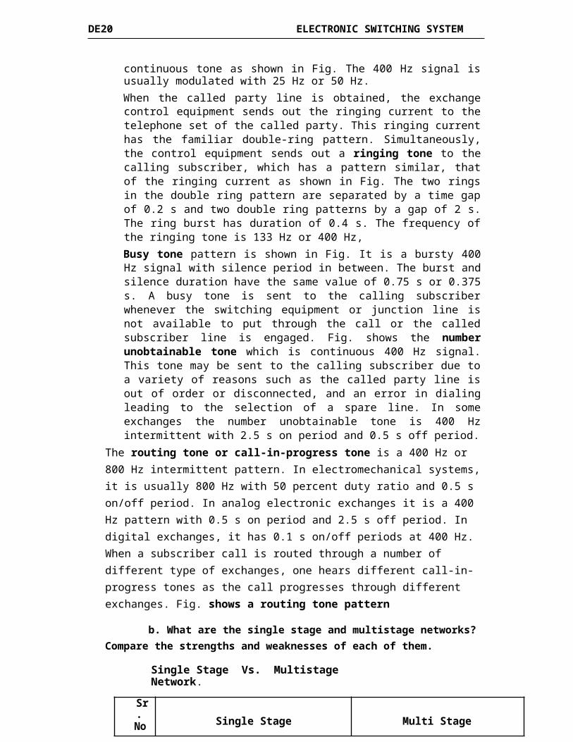
continuous tone as shown in Fig. The 400 Hz signal is usually modulated with 25 Hz or 50 Hz.When the called party line is obtained, the exchange control equipment sends out the ringing current to the telephone set of the called party. This ringing current has the familiar double-ring pattern. Simultaneously, the control equipment sends out a ringing tone to the calling subscriber, which has a pattern similar, that of the ringing current as shown in Fig. The two rings in the double ring pattern are separated by a time gap of 0.2 s and two double ring patterns by a gap of 2 s. The ring burst has duration of 0.4 s. The frequency of the ringing tone is 133 Hz or 400 Hz,Busy tone pattern is shown in Fig. It is a bursty 400 Hz signal with silence period in between. The burst and silence duration have the same value of 0.75 s or 0.375 s. A busy tone is sent to the calling subscriber whenever the switching equipment or junction line is not available to put through the call or the called subscriber line is engaged. Fig. shows the number unobtainable tone which is continuous 400 Hz signal. This tone may be sent to the calling subscriber due to a variety of reasons such as the called party line is out of order or disconnected, and an error in dialing leading to the selection of a spare line. In some exchanges the number unobtainable tone is 400 Hz intermittent with 2.5 s on period and 0.5 s off period.
The routing tone or call-in-progress tone is a 400 Hz or 800 Hz intermittent pattern. In electromechanical systems, it is usually 800 Hz with 50 percent duty ratio and 0.5 s on/off period. In analog electronic exchanges it is a 400 Hz pattern with 0.5 s on period and 2.5 s off period. In digital exchanges, it has 0.1 s on/off periods at 400 Hz. When a subscriber call is routed through a number of different type of exchanges, one hears different call-in-progress tones as the call progresses through different exchanges. Fig. shows a routing tone pattern
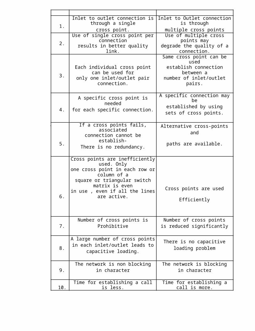
b. What are the single stage and multistage networks? Compare the strengths and weaknesses of each of them.
Single Stage Vs. Multistage Network.
Sr. Single Stage Multi StageNo.
1. Inlet to outlet connection is through a single Inlet to Outlet connection is throughcross point. multiple cross points
2. Use of single cross point per connection Use of multiple cross points mayresults in better quality link. degrade the quality of a connection.
Same cross point can be used
3.Each individual cross point can be used for establish connection between a
only one inlet/outlet pair connection. number of inlet/outlet pairs.
A specific cross point is needed A specific connection may beestablished by using
4. for each specific connection.sets of cross points.
If a cross points fails, associatedAlternative cross-points andconnection cannot be establish-
5. paths are available.There is no redundancy.
Cross points are inefficiently used. Onlyone cross point in each row or column of asquare or triangular switch matrix is even
Cross points are used6. in use , even if all the lines are active. Efficiently
Number of cross points is Number of cross points7. Prohibitive is reduced significantly
A large number of cross pointsThere is no capacitive
in each inlet/outlet leads to8. loading problem
capacitive loading.
The network is non blocking The network is blocking9. in character in character
10. Time for establishing a call is less. Time for establishing a call is more.
Q.5.a. How does the one arrive at the probability of availability of free lines during the busy hour?How can this be improved?
Ans:One can arrive at the probability of free lines during busy hour by using the delay probability of the exchange. The delay probability indicates the delay that a caller may face before his call can be completed. In a delay system the caller is made to wait till a free line is made available for the completion of the call. This leads to call delay. Improvement can be made if the system is treated as a loss system instead of a delayed system. In a loss system, the caller has to repeat a call till the call is established. This reduces the delay by releasing a caller from the queue until there is repeated action.Blocking probability can be useful. The blocking probability P is defined as the probability that all the servers in system are busy. When all the servers are busy, no further traffic can be carried by the system and the arriving subscriber’s traffic is blocked. At the first instance, it may appear that the blocking probability is the same measure as the GOS. The probability that all the servers are busy may well represent the fraction of the calls lost, which is what the GOS is all about.
b. Explain all the categories that are served by common control switching system.
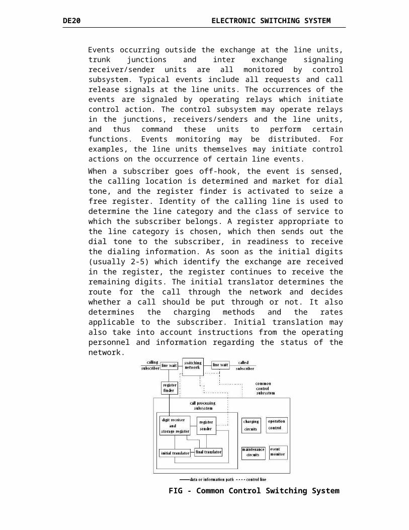
Common Control Switching System: A functional block diagram of a common control switching system is shown in Fig. The control functions in a switching system may be placed under four broad categories:
i. Event monitoring. ii. Call processing.
iii. Charging. iv. Operation and maintenance
45

DE20 ELECTRONIC SWITCHING SYSTEM
Events occurring outside the exchange at the line units, trunk junctions and inter exchange signaling receiver/sender units are all monitored by control subsystem. Typical events include all requests and call release signals at the line units. The occurrences of the events are signaled by operating relays which initiate control action. The control subsystem may operate relays in the junctions, receivers/senders and the line units, and thus command these units to perform certain functions. Events monitoring may be distributed. For examples, the line units themselves may initiate control actions on the occurrence of certain line events.
When a subscriber goes off-hook, the event is sensed, the calling location is determined and market for dial tone, and the register finder is activated to seize a free register. Identity of the calling line is used to determine the line category and the class of service to which the subscriber belongs. A register appropriate to the line category is chosen, which then sends out the dial tone to the subscriber, in readiness to receive the dialing information. As soon as the initial digits (usually 2-5) which identify the exchange are received in the register, the register continues to receive the remaining digits. The initial translator determines the route for the call through the network and decides whether a call should be put through or not. It also determines the charging methods and the rates applicable to the subscriber. Initial translation may also take into account instructions from the operating personnel and information regarding the status of the network.
FIG - Common Control Switching System
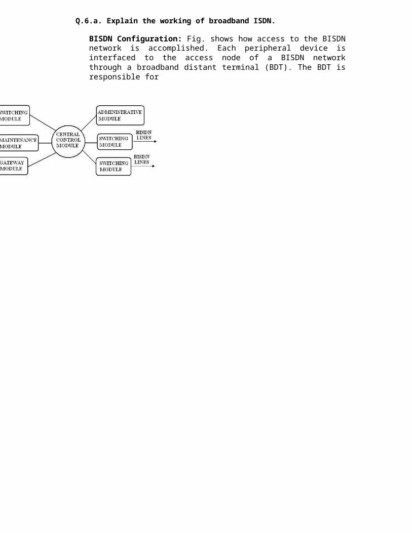
Q.6.a. Explain the working of broadband ISDN.
BISDN Configuration: Fig. shows how access to the BISDN network is accomplished. Each peripheral device is interfaced to the access node of a BISDN network through a broadband distant terminal (BDT). The BDT is responsible for
DE20 ELECTRONIC SWITCHING SYSTEM
electrical to optical conversion, multiplexing of peripherals, and maintenance of the subscriber’s local system. Excess nodes concentrate several BDT’s into high speed optical fiber line directed through a feeder point into a service node. Most of the control function for system excess is managed by the service node, such as call processing, administrative function and switching and maintenance functions. The functional modules are interconnected in a star configuration and include switching, administrative, gateway, and maintenance modules. The interconnection of the function module is shown in Fig. The central control hub acts as the end user interface for control signaling and data traffic maintenance. In essence, it oversees the operation of the modules.
b. What is the need of hybrid in telephone networks? How does it work?
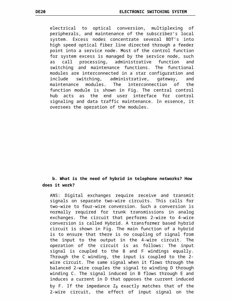
ANS: Digital exchanges require receive and transmit signals on separate two-wire circuits. This calls for two-wire to four-wire conversion. Such a conversion is normally required for trunk transmissions in analog exchanges. The circuit that performs 2-wire to 4-wire conversion is called Hybrid. A transformer based hybrid circuit is shown in Fig. The main function of a hybrid is to ensure that there is no coupling of signal from the input to the output in the 4-wire circuit. The operation of the circuit is as follows: The input signal is coupled to the B and F windings equally. Through the C winding, the input is coupled to the 2-wire circuit. The same signal when it flows through the balanced 2-wire couples the signal to winding D through winding C. The signal induced in B flows through E and induces a current in D that opposes the current induced by F. If the impedance ZB exactly matches that of the 2-wire circuit, the effect of input signal on the output winding D is completely nullified. In a similar way, the input signal from the subscriber end is completely nullified from coupling into the winding A.
25
DE20 ELECTRONIC SWITCHING SYSTEM
Q.7.a. Name the switching schemes used in a digital exchange. How call processing
take place?
Ans:The different switching systems used are:
1. Strowger Switching System2. Cross bar Switching.3. Electronic Switching System.
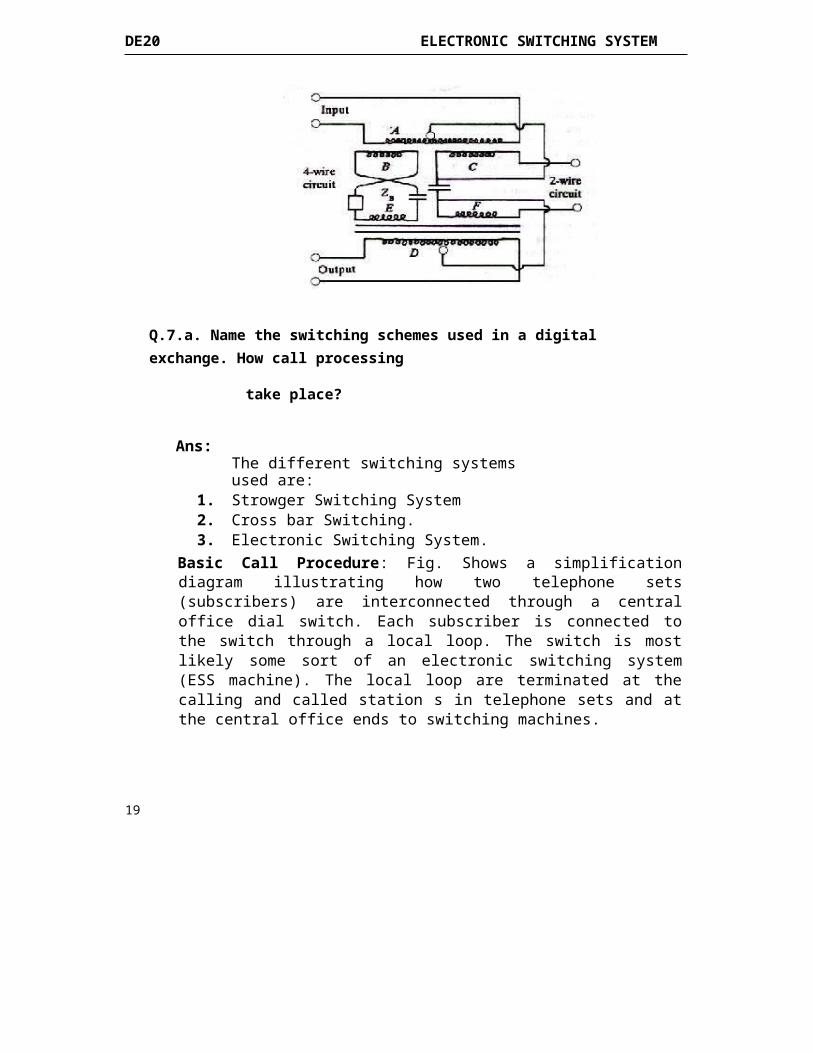
Basic Call Procedure: Fig. Shows a simplification diagram illustrating how two telephone sets (subscribers) are interconnected through a central office dial switch. Each subscriber is connected to the switch through a local loop. The switch is most likely some sort of an electronic switching system (ESS machine). The local loop are terminated at the calling and called station s in telephone sets and at the central office ends to switching machines.
19
DE20 ELECTRONIC SWITCHING SYSTEM
FIG - Telephone Call Procedure
When the calling party’s telephone set goes off hook (i.e., lifting the handset off the cradle), the switch hook in the telephone set is released, completing a dc path between the tip and the ring of the loop trough the microphone .The ESS machine senses a dc current in the loop and recognizes this as an off-hook condition. Completing a local telephone call between two subscribers connected to the same telephone switch is accomplished through a standard set of procedure that includes the 10 steps listed next.
1. Calling station goes off hook. 2. After detecting a dc current flow on the loop, the switching machine returns an audible dial tone to the calling station, acknowledging that the caller has access to the switching machine. 3. The caller dials the destination telephone number using one of the two methods: Mechanical dial pulsing or, more likely, electronic dual-tone multi frequency (Touch-Tone) signals. 4. When the switching machine detects the first dialled number, it removes the dial tone from the loop. 5. The switch interprets the telephone number and then locates the loop for the destination telephone number. 6. Before ringing the destination telephone , the switching machine tests the destination loop for dc current to see if tt is idle (on hook) or in use (off hook). At the same time, the switching machine locates a signal path through the switch between the two local loops. 7. (a) If the destination telephone is off hook, the switching machine sends a station busy signal back to the calling station.
(b) If the destination telephone is on hook, the switching machine sends a ringing signal to the destination telephone on the local loop and the same time sends a ring back signal to the calling station to give the caller some assurance that something is happening. 8. When the destination answers the telephone, it completes the loop, causing dc current to flow.
20
DE20 ELECTRONIC SWITCHING SYSTEM
9. The switch recognizes the dc current as the station answering the telephone. At this time, the switch removes the ringing and ring-back signals and completes the path through the switch, allowing the calling and called parties to begin conversation.10. When either end goes on hook, the switching machine detects an open circuit on that loop and then drops the connections through the switch.
b. How speech is transmitted in a digital switching environment using PCM/TDM?
Ans:A digital carrier system is a communications system that uses digital pulses rather than analogue signals to encode information. Fig shows the block diagram for a digital carrier system. This digital carrier system T1 uses PCM-encoded samples from 24 voice band channels for transmission over a single metallic wire pair or optical fibre transmission line. Each voice-band channel has a band width of approximately 300 Hz to 3000 Hz. Again, the multiplexer is simply a digital switch with 24 independent inputs and one time division multiplexed output. The PCM output signals from the 24 voice-band channels are sequentially selected and connected through the multiplexer to the transmission line.When a T1 carrier system, D-type (digital) channel banks perform the sampling, encoding and multiplexing of 24 voice-band channels, each channel contains an eight-bit PCM code and is sampled 8000 times a second. Each channel is sampled at the same rate. Fig. shows the channel sampling sequence for a 24-channel T1 digital carrier system. As the Fig. shows each channel is sampled once each frame but not at the same time. Each channel’s sample is offset from the previous channel’s sample by 1/24 of the total frame time. Therefore, one 64-kbps PCM-encoded sample is transmitted for each voice-band channel during each frame (a frame time of 1/8000 = 125 µs). Later, an additional bit (called the framing bit) is added to each frame. The framing bit occurs once per frame (8000-bps rate) and is recovered in the receiver, where it is used to maintain frame and sample synchronization between the TDM transmitter and receiver.
Q.8.a. What are the various types of signaling used in a switching network?
Signaling systems link the variety of switching systems, transmission systems and subscriber equipments in telecommunication network to enable the network to function as a whole.Three forms of signaling are involved in a telecommunication network:
1. Subscriber loop signaling.
2. Intra exchange or register signaling 3. Interexchange or inter register signaling
In a telephone network, subscriber loop signaling depends upon the type of a telephone instrument used.The intra exchange signaling is internal to the switching system and is heavily dependent upon the type and design of a switching system .It varies from one model to another even with the same manufacturer. This signaling does not involve signaling system of the type required on the switching network.When interexchange signaling takes place between exchanges with common control subsystems, it is called Inter register signaling. The main purpose of Inter register signaling is the exchange of address digits which pass from exchange to exchange on a link by link basis. Network wide signaling also involves end to end signaling between the originating exchange and the terminating exchange. Such a form of signaling is called line signaling. CCS does not use the speech or the data path for signaling. It uses a separate common channel for passing control signals for a group of trunks or information
In Channel Common ChannelTrunks are held up during Trunks are not required forsignaling. SignalingSignal repertoire is Extensive signal repertoire islimited. possible.Interference between voice No interference as the twoand Channels are physically separate.Control signals may occur.Separate signaling Only one set of signalling
36
DE20 ELECTRONIC SWITCHING SYSTEM
equipment is required for equipments is required for a wholeeach trunk and hence group of trunk Circuits andexpensive. therefore CCS
is economical
The voice channel beingthe control channel, there Control Channel is in generalis a possibility of potential in accessible to users.misuse by the customers.
Signaling is relatively Signaling is significantly fast.slow.Speech circuit reliability is There is no automatic test of theassured. speech circuit.It is difficult to change or There is flexibility to change oradd signals. add signals.It is difficult to handle
Signals during speech.signaling duringThere is freedom to handle
speech period.
Reliability of the signalingReliability of the signaling
path is notPath is critical.
Critical.
Common channel signaling is better than In-channel signaling.
b. Explain the various levels of CCITT signaling system number?
A block schematic diagram of the CCITT no. 7 signaling system is shown in fig. Signal messages are passed from the central processor of the sending exchange to the CCS system. This consists of the microprocessor based subsystem.The signaling control subsystems, the signaling termination subsystem and the error control subsystem. The signaling control subsystem structures the messages in the appropriate format and queues them for transmission. When there are no messages to send, it generates filler messages to keep the link active. Messages then passed to the signaling termination sub system, where complete signal units (SU) are assembled using sequence numbers and check bits generated by the error control subsystem. At the receiving terminal, the reverse sequence is carried out. The levels are as follows:
Level 1: The Physical LayerLevel 2: The Data Link LevelLevel 3: The signaling network level Level 4: The User Part
FIG – Block Schematic Diagram of CCITT No.7 Signally System
Q.9.a. Calculate the number of trunks that can be supported on a time multiplexed space switch given that, 32 channels are multiplexed in each stream, while the control memory access time is 100ns and the bus switching transferring time is 100ns per transfer.
b. Write short notes on
i. stored program control
ii. Congestion
iii. Common channel signaling
iv. PSTN
Ans.(i) Stored Program Control: In centralized control, all the control equipment is replaced by a single processor which must be quite powerful. It must be capable of processing 10 to 100 calls per second, depending on the load on the system, and simultaneously performing many other ancillary tasks. A typical control configuration of an ESS using centralized SPC is shown in Fig. A centralized SPC configuration may use more than one processor for redundancy purposes.In almost all the present day electronic switching systems using centralized control, only a two-processor configuration is used. A dual processor architecture may be configured to operate in one of three modes:
(i) Standby mode (ii) Synchronous duplex mode (iii) Load Sharing mode
FIG - Typically Centralized SPC Organization
(ii) CONGESTION: It is uneconomic to provide sufficient equipment to carry all the traffic that could possibly be offered to a telecommunication system. In a telephone exchange it is theoretically possible for every subscriber to make a call simultaneously. A situation can therefore arise when all the trunks in a group of
27
DE20 ELECTRONIC SWITCHING SYSTEM
trunks are busy, and so it can accept further calls. This state is known as congestion. In a message-switched system, calls that arrive during congestion wait in a queue until an outgoing trunk becomes free. Thus, they are delayed but not lost. Such systems are therefore called queuing systems or delay system. In a circuit-switched system, such as a telephone exchange, all attempts to make calls over a congested group of trunks are successful. Such systems are therefore called lost-call systems. In a lost-call system the result of congestion is that the traffic actually carried is less than the traffic offered to the system.(iii) Common channel signalling. Signaling systems link the variety of switching systems, transmission systems and subscriber equipments in telecommunication network to enable the network to function as a whole. Three forms of signaling are involved in a telecommunication network:
1. Subscriber loops signaling. 2. Intra exchange or register signaling 3. Interexchange or inter register signaling
In a telephone network, subscriber loop signaling depends upon the type of a telephone instrument used. The intra exchange signaling is internal to the switching system and is heavily dependent upon the type and design of a switching system. It varies from one model to another even with the same manufacturer. This signaling does not involve signaling system of the type required on the switching network. When interexchange signaling takes place between exchanges with common control subsystems, it is called Inter register signaling. The main purpose of Inter register signaling is the exchange of address digits which pass from exchange to exchange on a link by link basis. Network wide signaling also involves end to end signaling between the originating exchange and the terminating exchange. Such a form of signaling is called line signaling. CCS does not use the speech or the data path for signaling. It uses a separate common channel for passing control signals for a group of trunks or information paths. It gives the following advantages:
(i) Information can be exchange between the processors much more rapidly than when channel associated signaling is used.
(ii) As a result, a much wider repertoire of signals can be used and this enables more services to be provided to customers.
(iii) Signals can be added or changed by software modification to provide new services.
(iv) There is no longer any need for line signaling equipments on every junction which results in a considerable cost saving.
(v) Since there is no line signaling, the junctions can be used for calls from B to A in addition to calls from A to B. Both way working requires fewer circuits to carry the traffic than if separate groups of junctions are provided from A to B and from B to A.
(vi) Signals relating to a call can be sent while the call is in progress. This enables customers to alter connections after they have been set up. For example a customer can transfer a call elsewhere, or request a third party to be connected in to an existing connection.
(iv) PSTN the Public Switched Telephone Network: The Public Switched Telephone Network (PSTN) accommodates two types of subscribers: public and private. Subscribers to the private sector are customers who lease equipment, transmission media (facilities), and service from telephone companies on a permanent basis. The leased circuits are designed and configured for their use only and are often referred to as private line circuits or dedicated line circuits. For
28
ROLL NO.__________________ Code: AE64 Subject : TELECOMMUNICATION SWITCHING SYSTEMS
DE20 ELECTRONIC SWITCHING SYSTEM
example, large banks do not wish to share their communication network with other users, but it is not effective for them to construct their own networks. Therefore, banks lease equipment and facilities from public telephone companies and essentially operate a private telephone or data network within the PSTN. The public telephones companies are sometime called providers, as they lease equipment and provide service to other private companies, organizations, and government agencies. Most metropolitan area networks (MANs) and wide area networks (WANs) utilize private line data circuits and one or more service provider.
Subscribers to the public sector of the PSTN share equipment and facilities that are available to all the public subscribers to the network. This equipment is appropriately called common usage equipment, which includes transmission facilities and telephone switches. Anyone with a telephone number is a subscriber to the public sector of the PSTN. Since subscribers to the public network are interconnected only temporarily through switches, the network is often appropriately called the public switched telephone network (PSTN) and sometimes simply as the dial-up network. It is possible to interconnect telephones and modems with one another over great distance in fraction of a second by means of an elaborate network comprised of central offices, switches, cables (optical and metallic), and wireless radio systems that are connected by routing nodes (a node is a switching point). When someone talks about the public switched telephone network, they referring to the combination of lines and switches that from a system of electrical routes through the network.


![Answers & Solutions · izR;sd iz'u ds fy, vad fuEufyf[kr ifjfLFkfr;ksa esa ls fdlh ,d ds vuqlkj fn; ... tc IysV v pky ls xfr'khy gS] rc eq[; cy ds lkis{k v.kqvksa dh lkisf{kd pky](https://img.pdfslide.us/doc/110x75/5c9cbcb288c99388348b87de/answers-solutions-izrsd-izu-ds-fy-vad-fueufyfkr-ifjflfkfrksa-esa-ls-fdlh.jpg)