Embed Size (px)
Citation preview
PJM Manual 03:Transmission OperationsRevision: 60Effective Date: November 17, 2021
Prepared byTransmission OperationsPJM © 2021
Table of Contents
Table of Exhibits......................................................................................... 5
Approval...................................................................................................... 6
Current Revision.........................................................................................7
Introduction.................................................................................................8About PJM Manuals.............................................................................................................8About This Manual...............................................................................................................8Using This Manual...............................................................................................................9
Section 1: Transmission Operations Requirements............................. 101.1 Overview......................................................................................................................101.2 Responsibilities for Transmission Owner's Operating Entity........................................111.3 Transmission Operating Guidelines.............................................................................131.4 Reclosing Lines That Have Tripped.............................................................................17
1.4.1 PJM Mid-Atlantic Region.................................................................................171.4.2 PJM Western Region...................................................................................... 171.4.3 PJM Southern Region.....................................................................................18
1.5 PJM’s Real-Time Reliability Model.............................................................................. 181.5.1 Model Information and Data Requirements.................................................... 181.5.2 PJM Transmission System Model Update...................................................... 181.5.3 PJM Transmission Facilities............................................................................181.5.4 Reportable Transmission Facility....................................................................191.5.5 Observable Transmission Facility................................................................... 201.5.6 Monitored Transmission Facility......................................................................201.5.7 External Transmission Facilities......................................................................211.5.8 Non-PJM OATT Transmission Facilities......................................................... 221.5.9 Transmission Facilities Not Monitored by PJM............................................... 221.5.10 Local Facility Protection................................................................................221.5.11 Facilities under PJM Congestion Management (Reliability and Markets)
Control.................................................................................................................221.5.12 Process to Change the PJM Congestion Management Control Facilities
List.......................................................................................................................231.6 PJM Procedure to Assign Line Designations for New Facilities 500 kV and Above....231.7 PJM Procedure to Review Remedial Action Schemes (RAS)..................................... 24
Section 2: Thermal Operating Guidelines.............................................. 262.1 Thermal Limit Operation Criteria..................................................................................26
PJM Manual 03: Transmission OperationsTable of Contents
Revision: 60, Effective Date: 11/17/2021 PJM © 2021 2
2.1.1 Facility Ratings................................................................................................272.1.2 Short-Term Emergency Ratings......................................................................282.1.3 How to Change Facility Ratings......................................................................29
Section 3: Voltage & Stability Operating Guidelines.............................323.1 Voltage, Transfer, and Stability Limits..........................................................................323.2 Voltage Operating Criteria and Policy..........................................................................323.3 Voltage Limits.............................................................................................................. 35
3.3.1 Voltage Limit Exceptions.................................................................................363.4 Notification and Mitigation Protocols for Nuclear Plant Voltage Limits........................ 37
3.4.1 Communication...............................................................................................383.4.2 Information Exchange.....................................................................................38
3.5 Voltage Control Actions............................................................................................... 393.5.1 EHV Transformer LTC Operation....................................................................403.5.2 Voltage Control Options for Non-Tariff Facilities............................................. 403.5.3 Bulk Electric System Capacitor/SVC Operation..............................................413.5.4 Addressing Voltage Limits at Generators and other Non-PJM OATT
Facilities (including Distribution)..........................................................................443.5.5 Open-Ended Voltage Rise Analysis................................................................44
3.6 Low Voltage Operation................................................................................................ 453.7 High Voltage Operation................................................................................................463.8 Transfer Limits (Reactive/Voltage Transfer Limits)...................................................... 493.9 Stability Limits..............................................................................................................51
3.9.1 Process for Handling Generator Stability Limitations......................................523.10 Interconnection Reliability Operating Limit (IROL).....................................................533.11 Generator Voltage Schedules.................................................................................... 533.12 Reactive Reserve Check (RRC)................................................................................ 56
Section 4: Reportable Transmission Facility Outages..........................594.1 General Principles....................................................................................................... 594.2 Scheduling Transmission Outage Requests................................................................60
4.2.1 Outage Submittal Rules..................................................................................604.2.2 Hotline / In Service Work Requests / Protective Relay Outages / Failures.....624.2.3 Energizing New Facilities................................................................................634.2.4 Protection System Coordination..................................................................... 644.2.5 Generator Voltage Regulator Changes...........................................................644.2.6 Peak Period Outage Scheduling Guidelines...................................................644.2.7 Outage Scheduling Exceptions.......................................................................644.2.8 Emergency and Forced Outages....................................................................654.2.9 Rescheduling Outages....................................................................................654.2.10 Coordinating Outage Requests with Other TOs........................................... 664.2.11 Coordinating Outage Requests with other RTOs..........................................674.2.12 Coordinating Outage Requests with Planned Nuclear Generation
Outages...............................................................................................................674.2.13 Coordinating Outage Requests with Impacted Generators.......................... 67
PJM Manual 03: Transmission OperationsTable of Contents
Revision: 60, Effective Date: 11/17/2021 PJM © 2021 3
4.3 Processing Transmission Outage Requests................................................................684.3.1 Notification of Transmission Outages............................................................. 704.3.2 Real-Time Switching Notification Procedures.................................................71
4.4 Equipment Failure Procedures.................................................................................... 714.5 Transmission Outage Acceleration Process................................................................72
4.5.1 General Principles...........................................................................................724.5.2 Criteria for Outage Acceleration......................................................................734.5.3 Timelines for the Outage Acceleration Process..............................................734.5.4 Processing Transmission Outage Acceleration Requests.............................. 73
Section 5: Index and Operating Procedures for PJM RTO Operation................................................................................................................ 76
Attachment A: RAS Listing......................................................................77
Attachment B: Transmission Outage ‘Cut-In’ Ticket Guidelines......... 82
Attachment C: Requesting Voltage Limit Exceptions to the PJMBaseline Voltage Limits........................................................................ 85
Attachment D: Post Contingency Congestion ManagementProgram................................................................................................. 87
Attachment E: Automatic Sectionalizing Schemes...............................90
Attachment F: Short Term Emergency Ratings..................................... 91
Attachment G: Transmission Outage Ticket Best Practices................ 92
Revision History....................................................................................... 98
PJM Manual 03: Transmission OperationsTable of Contents
Revision: 60, Effective Date: 11/17/2021 PJM © 2021 4
Table of Exhibits
Exhibit 1: PJM Actual Overload Thermal Operating Policy.............................................30
Exhibit 2: PJM Post-Contingency Simulated Thermal Operating Policy.........................30
Exhibit 3: PJM Baseline Voltage Limits...........................................................................36
Exhibit 4: Capacitor Installations with PLCs................................................................... 42
Exhibit 5: Transmission Outage Request Process..........................................................69
PJM Manual 03: Transmission OperationsTable of Exhibits
Revision: 60, Effective Date: 11/17/2021 PJM © 2021 5
ApprovalApproval Date: 11/17/2021Effective Date: 11/17/2021Simon Tam, Manager
Transmission Operations
PJM Manual 03: Transmission OperationsApproval
Revision: 60, Effective Date: 11/17/2021 PJM © 2021 6
Current RevisionAdministrative Change
• Added a missing footnote in Attachment A
Revision 60 (11/17/2021):• Section 4.2.2 & 4.2.4 – Removed reference to PRC-001 standard due to retirement.
• Attachment A: Removed Elgin Unit Stability Trip Scheme due to upgrades in the area.
• Attachment A: Removed Susquehanna 500kV Catty Corner Scheme.
PJM Manual 03: Transmission OperationsCurrent Revision
Revision: 60, Effective Date: 11/17/2021 PJM © 2021 7
IntroductionWelcome to the PJM Manual for Transmission Operations. In this Introduction, you will findthe following information:
• What you can expect from the PJM Manuals in general (see “About PJM Manuals”).
• What you can expect from this PJM Manual (see “About This Manual”).
• How to use this manual (see “Using This Manual”).
About PJM ManualsThe PJM Manuals are the instructions, rules, procedures, and guidelines established by PJMfor the operation, planning, and accounting requirements of the PJM RTO and the PJM EnergyMarket. The manuals are grouped under the following categories:
• Transmission
• PJM Energy Market
• Generation and transmission interconnection
• Reserve
• Accounting and Billing
• PJM administrative services
For a complete list of all PJM Manuals, go to the Library section on PJM.com.
About This ManualThe PJM Manual for Transmission Operations is one of a series of manuals within theTransmission set. This manual focuses on specific transmission conditions and procedures forthe operation of the Bulk Electric System and Designated Transmission Facilities.
The PJM Manual for Transmission Operations consists of sections and attachments. Thesesections are listed in the table of contents beginning on page ii.
Intended AudienceThe Intended audiences for the PJM Manual for Transmission Operations are:
• PJM dispatchers
• PJM Operations Planning staff
• Transmission Owners / Operators
• Generation Owners / Operators
• Local Control Center dispatchers
• PJM Members
References
PJM Manual 03: Transmission OperationsIntroduction
Revision: 60, Effective Date: 11/17/2021 PJM © 2021 8
There are several reference documents that provide both background and detail. The PJMManual for Transmission Operations does not replace any of the information in thesereference documents. These documents are the primary source for specific requirements andimplementation details. The references to the PJM Manual for Transmission Operations are:
• Transmission Owners Agreement
• NYISO PJM Joint Operating Agreement
• EMS User’s Manual
• PJM M-01: Control Center and Data Exchange Requirements
• PJM M-02: Transmission Service Request
• PJM M-3A: Energy Management System (EMS) Model Updates and Quality Assurance(QA)
• PJM M-12: Balancing Operations
• PJM M-13: Emergency Operations
• PJM M-37: Reliability Coordination
• PJM M-38: Operations Planning
Using This ManualBecause we believe that explaining concepts is just as important as presenting the procedures,we start each section with an overview. Then, we present details and procedures. Thisphilosophy is reflected in the way we organize the material in this manual. The followingparagraphs provide an orientation to the manual’s structure.
What You Will Find In This Manual
• A table of contents that lists two levels of subheadings within each of the sections.
• An approval page that lists the required approvals and the revision history.
• Sections containing the specific guidelines, requirements, or procedures including PJMactions and PJM Member actions.
• Attachments that include additional supporting documents, forms, or tables in this PJMManual.
• A section at the end detailing all previous revisions of the PJM Manual.
PJM Manual 03: Transmission OperationsIntroduction
Revision: 60, Effective Date: 11/17/2021 PJM © 2021 9
Section 1: Transmission Operations RequirementsWelcome to the Transmission Operations Requirements section of the PJM Manual forTransmission Operations. In this section you will find the following information:
• An overview of the general services provided by PJM (see “Overview”).
• A description of PJM’s transmission operating guidelines (see “Transmission OperatingGuidelines”).
• A description of PJM’s Real-Time Reliability Model (see “PJM’s Real-Time ReliabilityModel”).
• A description of PJM Transmission Facilities (see “PJM Transmission Facilities”).
• A description of Transmission Owner facilities (see “Local Transmission Facilities”).
• Guidelines on how to modify facilities in the Transmission Facilities List (see “Facilitiesunder PJM Congestion Management Control”).
• An overview of how Remedial Action Schemes (RAS) are reviewed, approved,communicated, and documented.
1.1 OverviewPJM is the Reliability Coordinator for the PJM RTO and is responsible for all regional Reliabilitycoordination as defined in the NERC and Regional Standards and applicable PJM OperatingManuals.
PJM operates the transmission grid in compliance with good utility practice, NERC standards,and PJM policies, guidelines and operating procedures, including, but not limited to:
• This PJM Transmission Operations Manual,
• NERC and RRO Standards as references during normal and emergency operations ofthe PJM transmission grid,
• Individual Transmission Owners Operating Procedures submitted to PJM to identifyspecific operating problems that could affect operation of the interconnected PJMtransmission grid.
The Bulk Electric System (BES) is defined as facilities 100 kV and higher. Transmission Owners(TOs) shall operate the Bulk Electric System Facilities and all System Operating Limits (SOL)(see M-37) in accordance with the PJM Operating Manuals and follow PJM instructions relatedto PJM responsibilities, including, but not limited to:
• Rules regarding TOs performing the physical operation and maintenance of all facilitieswith SOL,
• Directing changes in the operation of transmission voltage control equipment,
• Taking those additional actions required to prevent an imminent Emergency Conditionor to restore the PJM transmission grid to a secure state in the event of a PJM systememergency.
PJM Manual 03: Transmission OperationsSection 1: Transmission Operations Requirements
Revision: 60, Effective Date: 11/17/2021 PJM © 2021 10
Note:PJM reviews this manual annually, with periodic updates as required. PJM coordinatesidentified issues with PJM TOs, PJM GOs and neighboring RCs. As PJM and neighboringReliability Coordinators deem necessary, PJM will facilitate conference calls that includeneighboring Reliability Coordinators, neighboring Transmission Operators, neighboringBalancing Authorities, PJM TOs and PJM GOs. PJM will notify PJM TOs and PJM GOsas necessary regarding issues communicated by neighboring Reliability Coordinators. PJMdistributes revisions to this manual to neighboring Reliability Coordinators, neighboringTransmission Operators, neighboring Balancing Authorities, PJM Transmission Owners andPJM Generation Operators.
Note:AEP is the registered TOP for the AEP 138 kV and below facilities. ITCI is the registered TOPfor its facilities. PJM is the registered TOP for all other BES facilities on the AEP transmissionsystem. Under normal operating conditions, AEP will coordinate with PJM to re-dispatchgeneration to control flows on their 138 kV and below monitored facilities. In an Emergency,a non-PJM registered TOP within the PJM footprint shall notify PJM of any unilateral actions ithas taken with respect to generation re-dispatch as soon as practicable, but no later than 30minutes, so that PJM is informed of the actions and can coordinate with impacted parties.
1.2 Responsibilities for Transmission Owner's Operating EntityThe responsibilities for a Transmission Owner's operating entity within PJM that are definedbelow are required to maintain the safe and reliable operation of the transmission system withinPJM. Transmission Owners operate and maintain the transmission system and are responsiblefor local reliability. The transmission Owner under PJM’s direction takes all actions required tomitigate transmission system reliability emergencies. The responsibilities identified below areconsistent with the NERC Functional Model for interconnected system operation.
This list is a collection of significant operational responsibilities and obligations of aTransmission Owner that are included in the PJM TOA and the PJM manuals. It is not intendedto be an all-inclusive list of every responsibility and obligation of a Transmission Owner.
• Subject to code of conduct.
• Establish ratings of its transmission facilities and provides these ratings to PJM (Section4.11 of TOA).
• Operates transmission facilities in accordance with good utility practice and PJMprocedures (Section 4.5 of TOA).
• Maintains transmission facilities in accordance with good utility practice and PJM policiesand procedures.
• Maintains appropriate voltage profiles.
• Provides local network integrity by defining operating limits, developing contingencyplans and monitoring operations if applicable.
PJM Manual 03: Transmission OperationsSection 1: Transmission Operations Requirements
Revision: 60, Effective Date: 11/17/2021 PJM © 2021 11
• Provides telemetry of transmission system to PJM and other Transmission Owners(Section 4.9 of TOA).
• Operates BES transmission system facilities under the direction of PJM (Section 4.5 ofTOA).
• Requests PJM to assist in mitigating operating limit violations.
• Implement procedures called for by PJM (Section 4.5 of TOA).
• Provide real-time operations information to PJM and other Transmission Owners asrequired.
• Provide maintenance and construction plans to PJM and other Transmission Owners asrequired.
• Takes action to maintain local reliability and public safety (Section 4.7 of TOA).
• All actions impacting BES facilities shall be approved by PJM unless immediate actionsare required to avoid loss of life, ensure safety or protect equipment. Such actions shallbe communicated to PJM as soon as practical.
• Supplies engineering data for transmission system models to PJM and otherTransmission Owners as required.
• Develops, documents, and communicates operator guidance, as necessary.
• Submit outage requests to PJM according to PJM requirements (Section 4.8 of TOA).
• Plan and coordinate transmission system outages with other transmission systemoperators as required (Section 4.8. of TOA).
• Work with other transmission system operators and PJM to mitigate identified reliabilityconcerns for planned system outages.
• The Transmission Owner shall notify PJM (verbally and via eDART) of any knownsingle contingency conditions that results in the loss of multiple generation units orany condition that prevent a generation unit to start-up after a trip. PJM will review thecondition and will update the EMS active contingency set accordingly. The resultantcontingency could be the largest MW lost in PJM and may result in additionalsynchronized reserve requirement (BAL-002-2).
• The Transmission Owner shall maintain a continuously staffed transmission controlcenter. The control center should meet all of the communication and information systemrequirements defined in the PJM manuals (Section 2 of PJM Manual 01: Control Centerand Data Exchange Requirements).
Note:Under circumstances where the Transmission Owner or Generator Operator cannot follow thedirective of PJM (such action would result in safety violation, damage equipment, or violateregulatory or statutory requirements), they shall immediately inform PJM of the inability toperform the directive so that PJM can implement alternate remedial actions.
PJM Manual 03: Transmission OperationsSection 1: Transmission Operations Requirements
Revision: 60, Effective Date: 11/17/2021 PJM © 2021 12
Note:A PJM Transmission Owner shall disconnect an affected facility if an overload on a transmissionfacility or an abnormal voltage or reactive condition persists and equipment is endangered. ThePJM Transmission Owner shall notify PJM prior to switching so PJM can perform a study, if timepermits, otherwise, immediately thereafter.
Personnel Requirements – Transmission system operators shall:
• Obtain required PJM Certification and Continuing Training Requirements (Section 1 andSection 2 of PJM Manual 40: Certification and Training Requirements).
• Be competent and experienced in the routine and abnormal operation of interconnectedtransmission systems.
• Be accountable to take any action required to maintain the safe and reliable operation ofthe transmission system.
• Have thorough knowledge of PJM procedures and their application.
• Have a working knowledge of NERC and applicable RRO Standards and how theycoordinate with PJM manuals.
• Have a working knowledge of adjacent transmission system operator’s switching andblocking procedures.
• Have an understanding of routine protection schemes for the PJM transmission system.
• Have knowledge of how to evaluate desired system response to actual systemresponse.
• Have knowledge of and be able to evaluate and take action on transmission systemequipment problems.
• Have knowledge of the general philosophy of system restoration and the philosophy andprocedures of their company as well as that of PJM.
• Have initial and continuing training that addresses the required knowledge andcompetencies and their application in system operations.
• Develop, document and maintain switching and blocking procedures consistent withOSHA 29 CFR Part 1910.269.
• Transmission system operators shall be accountable for directing field forces intransmission system switching activities.
• Follow-up on significant system events with an investigative process to analyze,document and report on operating abnormalities.
1.3 Transmission Operating GuidelinesPJM directs the operation to all SOL according to approved NERC Standards. In doing this,PJM considers transmission constraints, restrictions, and/or limitations in the overall operationof the PJM RTO. Describing this operation is the focus of this manual. The PJM RTO shall beoperated such that the following are not exceeded:
PJM Manual 03: Transmission OperationsSection 1: Transmission Operations Requirements
Revision: 60, Effective Date: 11/17/2021 PJM © 2021 13
• Transmission facility thermal limits
• Voltage limits
• Transfer limits
• Stability limits
• IROL
Although, the PJM RTO shall be operated such that limitations are not violated, it isrecognized that occasionally, for various reasons, thermal limitations can be exceeded for shortperiods under controlled conditions without adversely impacting system reliability or damagingequipment. All exceptions must be documented in Manual-03B. For example, the ConstraintManagement Mitigation procedure can be used during short time switching periods whenadhering to all of the requirements and parameters.
Should the PJM RTO at any time enter into an unknown operating state due to a catastrophicfailure of the ICCP links or loss of EMS analysis tools, it will be considered an Emergencyand operations shall be restored to respect proven reliable power system limits within 30minutes in accordance with NERC standards. PJM relies on Transmission Owners to serveas a back-up to PJM, monitoring BES facilities, when the PJM EMS is inoperable (TOP-007-0).PJM Transmission Owners shall notify PJM dispatch within 15 minutes when their TO analysispackages are unavailable (TOP-004-2 R4). In general, PJM may be in an unknown state whenboth PJM and TO analysis packages are unavailable.
PJM operates the PJM RTO so that immediately following any single malfunction or failure,the facility loadings are within appropriate thermal limits, while maintaining an acceptablevoltage profile. For details about PJM’s thermal operation, please see Section 2: ThermalOperating Guidelines. For more information about PJM’s voltage requirements, refer to Section3: Voltage and Stability Operating Guideline. These potential malfunctions or failures, suchas the sudden and unplanned loss of a generating unit, transmission line, or transformer, arecalled contingencies. PJM defines a contingency as a possible event resulting in the failure ormalfunction of one or more facilities.
PJM Dispatch utilizes EMS Network Applications and market tools in order to maintain systemreliability. Network applications evaluate pre/post-contingency thermal and voltage limits. Inaddition, the Transfer Limit Calculator (TLC) simulates transfers in order to assess voltagecollapse conditions for reactive interfaces. PJM Operators generate reports which providegenerator shift factors, phase angle regulator sensitivity factors, and load distribution factors.The information contained within these reports, the PJM State Estimator solution and unit bidinformation serves as the input data for PJM Market Tools. Through the use of PJM MarketTools, PJM Operators have the ability to use cost-effective generation adjustments to controlthermal/voltage constraints on a pre-contingency basis.
Note:PJM Transmission Owners that own BES facilities and serve load greater than 300 MW musthave a real-time analysis package or have their BES facilities be observable within another TOanalysis package.
PJM Manual 03: Transmission OperationsSection 1: Transmission Operations Requirements
Revision: 60, Effective Date: 11/17/2021 PJM © 2021 14
Prior to initiating redispatch to control flows within limit criteria, PJM Dispatch compares PJMEMS Security Analysis results with Transmission Owners EMS Security Analysis Results.Pre-contingency, Post-Contingency flows and ratings are compared. If a difference existsbetween PJM and Transmission Owner Security Analysis results, PJM will operate to the mostconservative results until the difference can be rationalized. If the difference is significant, thefollowing guides will be followed to quickly resolve the difference:
• PJM and Transmission Owner identify modeling issue and operate to most conservativesolution.
• PJM investigates modeling issue and attempts to resolve within 1 hour. This mayinvolve verification of distribution factors using Seasonal PSS/E load flow case orthe contingency definition via implementing contingency in a power flow solution andensuring switching devices are in their proper position.
• If discrepancy is > 5% and expected to last 2 hours, PJM Dispatch will contact PJMsupport staff and request Transmission Owner to contact support staff.
• PJM and Transmission Owner on-call support staff will work toward resolving modelingdifference.
• PJM and Transmission Owner agree to defer to most accurate analysis in lieu ofoperating to most conservative results, when difference is understood or resolved.
• PJM and Transmission Owner support staff attempt to correct modeling differenceswithin 24 hours.
Contingency Analysis• Single Contingency — One event that takes one or more facilities out of service. A
Single Facility is any one component/facility with impact to the BES, excluding bussections that can be removed from service by its own primary relay and breakerprotective equipment. Single contingencies may disconnect multiple generating facilities(plant with single connection leads to the bulk power system) or multiple transmissionfacilities (radial lines with tapping substations) from service.
• PJM Security Analysis applications simulate the single facility failure or malfunctionof critical equipment (facilities simulated in contingency analysis are not restricted tothe PJM monitored facility list) including lines, transformers, Phase Angle Regulators(PARs), generators, capacitors, and reactors whose loss or failure could result in limitviolations on PJM Monitored Facilities.
Note:PJM does not normally model or operate to single breaker failures due to the low probabilityof occurrences; however, PJM Manual-03B contains an operating procedure to mitigate singlebreaker failures.
PJM Manual 03: Transmission OperationsSection 1: Transmission Operations Requirements
Revision: 60, Effective Date: 11/17/2021 PJM © 2021 15
Note:Under some unusual conditions, including severe weather or other special circumstances sucha change to the Homeland Security Level, PJM should consider implementing conservativeoperation including control for the simultaneous occurrence of more than one contingency,substation circuit breaker outages, circuit breaker failure, and substation bus outages asappropriate (PJM M-13: Emergency Operations, Sections 3 and 4).
PJM uses appropriate pre and post contingency procedures which are documented in thismanual to:
• Maintain acceptable voltage levels• Maintain operation within stability limits• Maintain operation within transfer limits• Minimize the risk of cascading interruptions to the transmission system• Prevent physical damage to system transmission facilities• Eliminate thermal overloads
The consequences of violating these limits may lead to PJM RTO instability, voltage collapse,equipment damage, or loss of customer load. The objective of PJM is to operate thetransmission facilities such that system reliability is maintained. Once a contingency occursthe system is readjusted as required and analysis for the next worst contingency is performed.The PJM dispatcher directs actions to restore the system to an acceptable state. For moreinformation see Section 2: Thermal Operating Guidelines and Section 3: Voltage and StabilityOperating Guidelines.
• Double Contingency — Two different events that occur simultaneously and result in theloss of two or more facilities.
Note:A single contingency can consist of one or more transmission facilities. A double circuit towerline (DCTL) contingency is the simultaneous loss of two single contingencies.
Note:If a Transmission Owner wishes to operate to control for DCTL contingencies, it may do sousing its own internal equipment after communicating with the PJM dispatcher.
Note:PJM system operations will implement actions to control for system congestion caused byDCTL contingencies resulting from the declaration of Conservative Operations. PJM will issue aPCLLRW when calculated post-contingency flows exceed Long Term Emergency (LTE) ratings.PJM will initiate redispatch of generation when calculated post-contingency flows exceed theLoad Dump (LD) rating permitting off-cost generation to set LMP.
PJM Manual 03: Transmission OperationsSection 1: Transmission Operations Requirements
Revision: 60, Effective Date: 11/17/2021 PJM © 2021 16
1.4 Reclosing Lines That Have TrippedThe PJM RTO uses varied philosophies when reclosing EHV (Extra High Voltage, defined as345 kV and above) lines that have tripped and the automatic reclose has not been successful.These philosophies differ based on the EHV line automatic reclosing design and operatingpractice.
Note:Transmission Owners shall promptly notify PJM of any BES facility that have tripped andcoordinate restoration efforts.
1.4.1 PJM Mid-Atlantic RegionIf an EHV aerial transmission line trips and does not automatically reclose, it should bemanually reclosed within five minutes after tripping. If an EHV line trips and returns to serviceby automatically reclosing (or by manually reclosing if auto reclosing fails to occur and theline is tried-back once manually), the PJM dispatcher is authorized to operate at the currenttransfer levels or at reduced transfer levels. If an EHV line trips and does not return to servicewhen reclosed automatically (or if manual reclosing also fails after the line is tried-back oncemanually), PJM performs the following activities:
• Immediately reduces the reactive operating limits to the level with the line out-of-service.• Order the line to be tried-back within five minutes after conferring with the Transmission
Owner(s) of the line.
If the line returns to service after the five minute try-back, the reactive operating limits mayremain reduced until a patrol of the line has been completed or until the PJM dispatcher judgesthat the limit reduction is no longer necessary. If the aerial patrol does not locate the causeof the tripping, the reactive operating limits should be returned to normal. The TransmissionOwners, however, must complete a foot patrol of the circuit no later than the next daylight period(weather permitting).If an EHV line that was successfully reclosed 5 minutes after the trip-out trips a second time,the transfer limit should be re-evaluated and reduced if necessary until patrol is completed (orthe source of the trouble is definitely determined by another means - aerial patrol, report oftrouble, etc.). Manual try-backs on lines which trip a second time after having been successfullyreclosed five minutes after tripping are not attempted until some period of time has elapsed (30minutes or longer). PJM directs reclosing with the concurrence of the Transmission Owners.
1.4.2 PJM Western RegionThe majority of the First Energy South 345 kV and 500 kV circuits utilize a high speed recloseof approximately 28 cycles without sync check and 34 cycles with sync check. The time delayedreclose varies greatly from station to station and is given in section IV.C.5 of the First EnergySouth System Operations Manual. Phase angle closing requirements also vary and are alsogiven in the same section of the Manual.If an EHV circuit locks out after a high speed reclose and one time delay reclose; FE Southwill patrol the circuit prior to trying it again. If a circuit utilizes supervisory control for one of itsreclose attempts, FE South will evaluate the weather conditions prior to trying a supervisoryreclose.
PJM Manual 03: Transmission OperationsSection 1: Transmission Operations Requirements
Revision: 60, Effective Date: 11/17/2021 PJM © 2021 17
The Duke Energy Ohio-Kentucky 345 kV and 138 kV transmission circuits utilize automaticreclosing. If a circuit locks out after an automatic reclose, DEOK will patrol the circuit beforeattempting a reclose. For any supervisory reclose attempts, DEOK will work with PJM toevaluate weather, system, and equipment conditions prior to attempting the reclose.
1.4.3 PJM Southern RegionThe Dominion Virginia Power 500 kV transmission lines within the PJM Southern region willautomatically reclose multiple times. If the line goes to lockout, it is not to be reclosed manuallyuntil the line has been patrolled by Dominion Virginia Power operations personnel.
1.5 PJM’s Real-Time Reliability ModelPJM’s Real-Time Reliability Model is a computer representation of the power system facilitiesin the PJM RTO and other Balancing Authorities that may impact the reliable operation ofthe PJM system. The model resides and is maintained by the PJM staff on the PJM EnergyManagement System (EMS). The PJM EMS Network Application programs utilize the modelto continuously calculate the real-time state and determine the security of the PJM system.The Security Constrained Economic Dispatch (SCED) dispatches every generator in the model.The model is also used to calculate real-time Locational Marginal Prices. The model is createdand maintained from input data received by PJM from various sources including TransmissionOwners, Generation Owners, Load Serving Entities, and other Balancing Authorities. The modelis only as accurate as the input data used to derive it; therefore, timely and accurate dataupdates are critical.
1.5.1 Model Information and Data Requirements• The Transmission Owner is responsible to provide the information and data needed by
PJM about the Transmission Owner System.• Telemetry data requirements are defined in the PJM M-01: Control Center and Data
Exchange Requirement.• System analytical model information and update requirements are defined in the PJM
M-3A: Energy Management System (EMS) Model Updates and Quality Assurance (QA).
1.5.2 PJM Transmission System Model UpdatePJM performs periodic updates to the PJM Real-Time Reliability Model. The Data ManagementSubcommittee representative must submit timely transmission model changes to be includedin these updates consistent with the requirements contained within the PJM M-3A: EnergyManagement System (EMS) Model Updates and Quality Assurance (QA).
1.5.3 PJM Transmission FacilitiesPJM Transmission Facilities are those facilities used in the transmission of electrical energythat:
• Are included in the PJM tariff.• Have demonstrated to the satisfaction of PJM to be integrated with the PJM RTO
Transmission System, and integrated into the planning and operation of the PJM RTO toserve all of the power and transmission customers within the PJM RTO.
PJM Manual 03: Transmission OperationsSection 1: Transmission Operations Requirements
Revision: 60, Effective Date: 11/17/2021 PJM © 2021 18
• Transmission facilities that meet all other requirements including having sufficienttelemetry to be deemed ‘observable’ by the PJM State Estimator, PJM NetworkApplications, or the PJM Real-Time Reliability Model can be considered for inclusionas monitored for real-time and contingency analysis for the purpose of identifyingtransmission constraints.
• The Transmission Owner of a facility that meets all requirements, including observabilityfor the Real-Time Model, (see “Monitored Transmission Facilities”) must specificallyrequest that a facility be “Monitored” by PJM using the process and timeline identifiedat the end of this section (see “Process to Change the PJM Congestion ManagementFacilities List).
• Each Transmission Owner must specifically identify any tariff facility that is not under theoperational control of PJM.
• Include NERC BES facilities.
1.5.4 Reportable Transmission FacilityTransmission Owners are required to report scheduled and forced outages for ReportableTransmission Facilities. Outage information is reported through eDART and through the statusobtained via computer link to the EMS. In general, a Transmission Facility is reportable if achange of its status can affect, or has the potential to affect, a transmission constraint onany Monitored Transmission Facility or otherwise impedes the free-flowing ties within the PJMRTO and adjacent areas. All Transmission Facilities included in the PJM Reliability Modelmust be reported to PJM with as much advance notice as possible. The PJM Web site (http://www.pjm.com/markets-and-operations/ops-analysis/transmission-facilities.aspx) lists ReportableTransmission Facilities by Transmission Zone. Transmission Owners are responsible forensuring the accuracy of this data. Updates are made as required correlating to systemmodel updates. Note that ALL Congestion Management (monitored) and Reliability Coordinationfacilities are to be included by default as Reportable Transmission Facilities. As explainedabove, PJM has also identified other facilities as Reportable Transmission Facilities, becausethey can affect the overall transmission system. Instructions and a timeline for reporting outagesare provided in Section 4 of this manual under the heading Reportable Transmission FacilityOutages.Codes associated with Reportable Facilities are defined as:Yes, Reportable;
• The facility must be modeled in the PJM EMS and status information must be conveyedto the PJM EMS via the data link;
• The TO must generate eDART tickets when facility outages are required; and,• Call the PJM dispatcher to ensure proper communication and coordination of switching
and system security.
Low-Priority Reportable;• The facility must be modeled in the PJM EMS and status information must be conveyed
to the PJM EMS via the data link; and,• The TO must generate eDART tickets when facility outages are required.
PJM Manual 03: Transmission OperationsSection 1: Transmission Operations Requirements
Revision: 60, Effective Date: 11/17/2021 PJM © 2021 19
• Call the PJM dispatcher when the facility is returned to service to ensure proper timestamp.
No, Not Reportable;• The facility may, or may not, be in the PJM EMS model; and,• The facility is not expected to significantly impact PJM system security or congestion
management.
With the growth of Reportable Facilities included in the PJM model, the Low-Priority ReportableCode is expected to accommodate the need to have facility status accurately modeled whilereducing the need for phone calls to coordinate outages and streamlining this process.PJM may require that all Tariff Facilities are Reportable. All EHV, 230 kV, and all tie-line facilitiesare flagged as Yes, Reportable and are not eligible for Low-Priority Reportable status. TariffFacilities will generally default to Yes, Reportable. It may be acceptable to consider selectedlower voltage Tariff facilities (161 kV, 138 kV, 115 kV and 69 kV) as Low-Priority Reportabledepending upon the impact of the facility upon system security and/or congestion management.With recommendations from the TO, the PJM Manager, Power Systems Modeling Departmentis responsible for re-assigning Tariff facilities as Low-Priority Reportable or Not Reportable.PJM operating studies focus on the impact of Reportable Facilities upon security. It is theTO's responsibility, after internal study, to ensure that system security will not be adverselyimpacted for the outage of a Low-Priority facility. The TO must notify PJM of a potential problemassociated with a Low-Priority Reportable facility outage prior to switching. The TO shouldprovide 30 minutes’ notice to the Power Director in order for PJM to confirm the TO’s analysisand make the appropriate adjustments. If, as a result of a Low-Priority Reportable outage, anunanticipated system security violation occurs, PJM will direct the TO to return the facility toservice.
1.5.5 Observable Transmission Facility• The term “observable” indicates that sufficient real-time analog and digital telemetry is
supplied to PJM such that it is possible to accurately calculate the bus voltage and/orMVA flow for the facility in question.
• Facility must be accurately modeled in PJM EMS.• The facility must have sufficient redundancy of telemetry to be “observable” in the PJM
State Estimator.
1.5.6 Monitored Transmission FacilityMonitored Transmission Facilities are an Observable Facility and are broken into 2 categories:
• Monitored for Markets and Reliability Facilities are accepted for congestion control.• Monitored for Reliability Facilities does not permit congestion to set LMP.
Both are monitored and controlled for limit violations using PJM’s Security Analysis programs.Control of limit violations to Monitored Transmission Facilities may result in constrainedoperation including manual redispatch; redispatch setting LMP and TLR curtailments. Additional
PJM Manual 03: Transmission OperationsSection 1: Transmission Operations Requirements
Revision: 60, Effective Date: 11/17/2021 PJM © 2021 20
details are contained within the PJM Balancing Operations Manual (M-12), Attachment B:Transmission Constraint Control Guidelines.PJM OATT Facilities shall be monitored for any of the following criteria:
• Vital to the operation of the PJM RTO.• Affects the PJM RTO’s interconnected operation with other Balancing Authorities.• Affects the capability and reliability of generating facilities or the power system model
that is used by PJM to monitor these facilities.• Significantly impact transmission facilities if outaged.• Affects the PJM Energy Market if outaged.• May result in constrained operations to control limit violations.• A NERC BES facility.
PJM must be provided the applicable normal, emergency, and load dump ambient ratings forthe transmission facility. Applicable ratings include sixteen ambient temperature sets (32F –95F, day and night) and limiting equipment identification.
• Monitoring requested by the Transmission Owner.
The monitored facilities are included in the Transmission Facilities List. The TransmissionFacilities List is located on the PJM website (http://www.pjm.com/markets-and-operations/ops-analysis/transmission-facilities.aspx).Transmission Owners may add an Observable Transmission Facility as a MonitoredTransmission Facility under PJM monitoring and control by sending notice to the Manager,PJM Power Systems Modeling Department. A Monitored Transmission Facility shall remain aMonitored Controllable Transmission Facility until the Transmission Owner requests in writingfor it to be removed. See the previous information on Observable Transmission FacilitiesDiscussion.
Note:The PJM EMS has the capability to monitor contingency flows on any device such as a circuitbreaker. The capability is known as Flow Device. Transmission Owners can submit ratings,as outlined in PJM Manual 3A, for devices/circuit breakers with limitations. The device/circuitbreaker ratings will be monitored as part of the PJM EMS Security Analysis. Facility ratings canbe found on the OASIS at the following link:http://www.pjm.com/markets-and-operations/etools/oasis/system-information/ratings-information.aspx.
1.5.7 External Transmission FacilitiesThose transmission facilities outside PJM RTO and/or facilities not entitled to transmissionservice under the PJM OATT are, for the purpose of transmission operations, consideredexternal transmission facilities.
PJM Manual 03: Transmission OperationsSection 1: Transmission Operations Requirements
Revision: 60, Effective Date: 11/17/2021 PJM © 2021 21
1.5.8 Non-PJM OATT Transmission FacilitiesThe Transmission Owners are responsible for the operation of their transmission facilities notincluded in the PJM OATT or at a lower voltage level than NERC BES facilities; provided,however, that the operation of these facilities does not compromise the reliable and secureoperation of other transmission facilities within the PJM RTO. Transmission Owners areexpected to comply with requests from PJM to take such actions with respect to coordination ofthe operation of their facilities not included in the PJM OATT as may be necessary to preservethe reliable and secure operation of the PJM RTO. At the request of the Transmission Owner,PJM will assist the Transmission Owners in alleviating any constraint within the PJM RTO.Because PJM may dispatch and schedule generation to alleviate a constraint only on a PJMOATT Facility, Transmission Owners do not rely on PJM procedures to control constraints onany facility not included in the PJM OATT. Generation assignments for transmission limitationson Non-PJM OATT facilities are the financial obligation of the Transmission Owner. Generationassignments for limits based on generating station/equipment limits on Non-PJM OATT facilitiesare the financial obligation of the Generation Owner requesting the limit.
1.5.9 Transmission Facilities Not Monitored by PJMThe Transmission Owners are responsible for the operation of their Local Area TransmissionFacilities and facilities that are included in the PJM tariff but not “PJM Monitored TransmissionFacilities”. However, the operation of Local Area Transmission Facilities should not compromisethe reliable and secure operation of other transmission facilities in the PJM RTO. TransmissionOwners are expected to comply with requests from PJM to take such actions with respect tocoordination of the operation of their Local Area Transmission Facilities as may be necessary topreserve the reliable and secure operation of the PJM RTO.
1.5.10 Local Facility ProtectionAt the request of the Transmission Owner, PJM will assist the Transmission Owners inalleviating any local area constraint or condition. PJM may dispatch and schedule generationto alleviate a constraint only on Monitored Transmission Facilities, therefore TransmissionOwners should not rely on PJM operating procedures to control constraints on their Non-Tarifffacilities, Local Transmission Facilities or non-monitored facilities. Generation assignmentsfor transmission limitations on non-monitored facilities are the financial obligation of theTransmission Owner.
1.5.11 Facilities under PJM Congestion Management (Reliability and Markets) ControlPJM has developed requirements that Transmission Owners must follow in order for PJM tooperate generation to control loading or voltage on transmission facilities. All facilities undercongestion management must be observed in the PJM EMS with sufficient telemetry to provideaccurate and reliable state estimation (some redundant metering is generally required).Generally, the Telemetry Requirements for Congestion Management Control are:For a transmission facility to be under PJM Congestion Management Control, the facility mustbe “observable” (as defined later in this section) with sufficient telemetry redundancy in the PJMState Estimator. In general, the telemetry requirements for a line/transformer to be “observable”with sufficient redundancy are:
• The branch has MW/MVAR telemetry at both ends and there is some MW/MVARtelemetry for other branches/injections at buses connecting to the branch.
PJM Manual 03: Transmission OperationsSection 1: Transmission Operations Requirements
Revision: 60, Effective Date: 11/17/2021 PJM © 2021 22
OR• The branch has MW/MVAR telemetry at only one end there is good MW/MVAR telemetry
for other branches/injections at buses connecting to the branch.
OR• The branch has no MW/MVAR telemetry at either end but it has almost perfect MW/
MVAR telemetry for other branches/injections at buses connecting to the branch.
In general, the telemetry requirements for a bus to be “observable” are:• The bus has at least one voltage telemetry point and it also has some MW/MVAR
telemetry for its branches and injections.
OR• The bus does not have any voltage telemetry point but a voltage telemetry point is
available at the immediate neighbor bus (of the same voltage level) AND the bus beingevaluated has most of the MW/MVAR telemetry for its branches and injections.
Note:See PJM M-01: Control Center and Data Exchange Requirements for specific requirements.
1.5.12 Process to Change the PJM Congestion Management Control Facilities ListThe process and timeline required to make adjustments to the existing Congestion ManagementControl Facilities List is described in detail in the PJM M-3A: Energy Management System(EMS) Model Updates and Quality Assurance (QA).
1.6 PJM Procedure to Assign Line Designations for New Facilities 500kV and AboveThe following details the PJM process for assigning line designations for new facilities 500 kVand above:
• PJM Transmission Planning receives approval from PJM Transmission ExpansionAdvisory Committee (TEAC) and PJM Board for new 500 kV and above facilities.
• PJM Transmission Planning notifies PJM Operations Planning (OPD) of approval of new500 kV and above facility.
• PJM OPD reviews the new circuit configuration and the master list of existing PJM 500kV and above facilities.
• PJM OPD notifies the appropriate TO of the preliminary designated line number.
• PJM OPD proposes the new circuit designation to:
o Manager Dispatch.
o Manager EMS Support.
o Manager Power Systems Modeling.
PJM Manual 03: Transmission OperationsSection 1: Transmission Operations Requirements
Revision: 60, Effective Date: 11/17/2021 PJM © 2021 23
o Manager Transmission Planning.
o Manager Forward Market Operations.
o Manager Real-Time Market Operations.
• Upon PJM internal approval, PJM OPD finalizes the new proposed designation bynotifying:
o PJM: Dispatch, EMS Support, Power Systems Modeling, and Transmission Planning.
o Committees: SOS-T, PC, and OC.
o TO: Appropriate TOs.
1.7 PJM Procedure to Review Remedial Action Schemes (RAS)The following details the PJM and committee structure review process for Remedial ActionSchemes (RAS) and general timeline. The process is applicable to new, retiring, orfunctional modified schemes. The procedure is designed to ensure sufficient analysis, notice,documentation, PRC-012-2 requirements, and training on these RAS are established ahead ofimplementation. The process is outlined in the following steps:
1. All proposed new RASs must meet the NERC RAS definition.
2. Owner forwards scheme to PJM for review by submitting PRC-012-2 Attachment 1 viathe email address [email protected] (PRC-012-2 R1).
3. PJM Planning, PJM Operations Planning, and Transmission Owner(s) review schemeand system impact using PRC-012-2 Attachment 2. PJM will provide feedback to theowner within four full calendar months of receipt or on a mutually agreed upon schedule(PRC-012-2 R2).
a. PJM will provide a recommendation to the owner, including if the scheme meets theRAS definition.
b. PJM will also identify whether the scheme is needed for reliability purposes includingoperational performance.
c. If the scheme is required for immediate reliability concerns, operational performance,or to restore the system to the state existing prior to a significant transmission facilityevent:
i The scheme will be implemented as soon as possible.
ii PJM will use reasonable best efforts to post the RAS information immediately.
4. PJM documents the scheme and revises Manual-03B.
5. RAS/SPS owner discusses the scheme at the PJM Committees, ultimately achieving fullReliability Coordinator endorsement through the stakeholder process. The Committeereview should be done in the following order to allow technical feedback to be addressedprior to the higher Committee review:
a. PJM System Operations Subcommittee (SOS).
b. PJM Relay Subcommittee (RS) (conditional).
PJM Manual 03: Transmission OperationsSection 1: Transmission Operations Requirements
Revision: 60, Effective Date: 11/17/2021 PJM © 2021 24
i Only for RAS impacting facilities 200 kV and above. The review can be doneprior to the SOS meeting depending on the meeting schedules.
c. PJM Operating Committee (OC).
d. PJM Market Implementation Committee (MIC).
e. PJM Planning Committee (PC).
f. PJM Markets and Reliability Committee (MRC).
6. PJM discusses the scheme at the PJM Dispatcher Training Subcommittee.
The committee review of the RAS and documentation process should be completed withintwo months. For a new and modified RAS not required for immediate reliability concerns,operational performance, or to restore the system to the state existing prior to a significanttransmission facility event, a minimum of 90 days will be required between posting the RASinformation and the actual implementation date of the RAS.
RAS owners shall submit results of operational performance analysis pursuant to PRC-012-2Requirement 5 and Corrective Action Plans (CAPs) pursuant to PRC-012-2 Requirements 6 and7 to [email protected].
Note:PJM will periodically evaluate RAS for retirement. When PJM identifies a scheme that may nolonger be needed, PJM will discuss and assess with both the RAS owner and the TransmissionOwner(s).
The retirement evaluation may be triggered by several factors:
1. RTEP project that the scheme is associated with has been completed.
2. Reliability issue that the scheme was designed to address no longer exists.
3. System changes have mitigated the congestion the scheme was designed to address.
4. Scheme has not been armed for several years.
PJM will evaluate operationally impactful external RASs on an annual basis. PJM will considerregistered RASs based on neighboring TOP/RC feedbacks and will study their impact on thePJM system. For impactful external RASs, PJM will include their status in Operations Planningstudies and in Real-time assessments (TOP-001-4 R10.5).
PJM Manual 03: Transmission OperationsSection 1: Transmission Operations Requirements
Revision: 60, Effective Date: 11/17/2021 PJM © 2021 25
Section 2: Thermal Operating GuidelinesWelcome to the Thermal Operating Guidelines section of the PJM Manual for TransmissionOperations. In this section you will find the following information:
• How PJM operates to prevent thermal problems (see “Thermal Limit OperationsCriteria”).
2.1 Thermal Limit Operation CriteriaThe PJM RTO is operated so that loading on all PJM SOL are within normal continuous ratings,and so that immediately following any single facility malfunction or failure, the loading on allremaining facilities can be expected to be within emergency ratings. (All deviations from normalprocedure must be approved and documented in PJM Manual-03B.)
This principle requires that actions should be taken before a malfunction or failure occursin order to control post-contingency loading on a pre-contingency basis. Some examples ofpossible pre-contingency actions include pre-arranged approved switching, use of approvedspecial purpose relays, Phase Angle Regulator tap adjustments (PARs), redispatch, andtransaction curtailment. These actions can be used pre-contingency to control post-contingencyoperation so as not to exceed emergency ratings. These pre-contingency options are simulatedby PJM when performing the day-ahead analysis of the system.
Following any malfunction or failure, all remaining facilities or procedures of PJM are utilized,as required in accordance with Exhibit 1 or as practical, to restore PJM RTO conditions within30 minutes to a level that restores operation within normal ratings and protects against theconsequences of the next malfunction or failure. Transmission overloads, both actual and post-contingency, are corrected within this time requirement. PJM uses the following techniques tocontrol contingency or system violations:
• Adjusting PARs.
• Switching reactive devices in/out of service or adjusting generator MVAR output.
• Switching transmission facilities in/out of service.
• Adjusting generation MW output via redispatch.
• Adjusting imports/exports.
• Issuing a TLR (Transmission Loading Relief).
If the above directed actions do not relieve an actual or simulated post-contingency violation,then emergency procedures may be directed, including dropping or reducing load as required.
A Transmission Owner has the right to use its own devices after coordinating with PJM (i.e.,Phase Angle Regulators - PARs) to correct for double circuit tower line contingency overloadsin their own system, ensuring that this corrective action does not aggravate an existingcontingency or create a new contingency. When a Transmission Owner detects a doublecircuit tower line contingency and the PJM RTO detects a single contingency, both of whichrequire different corrective strategies, the Transmission Owner and the PJM RTO dispatcherscommunicate to work out an overall solution for both problems, provided the net impact in MWs
PJM Manual 03: Transmission OperationsSection 2: Thermal Operating Guidelines
Revision: 60, Effective Date: 11/17/2021 PJM © 2021 26
shifted for other Transmission Owners does not exceed that which is required for the singlecontingency.
Note:Under normal operations, PJM does not operate for double-circuit tower line (DCTL)contingencies. However, PJM may operate for DCTL contingencies if Conservative Operationsare declared.
Note:Generation redispatch for DCTL contingencies will be borne by the Transmission Owner and willnot be allowed to set LMP while not under Conservative Operations.
Note:PJM system operations will implement actions to control for system congestion caused byDCTL contingencies resulting from the declaration of Conservative Operations. PJM will issue aPCLLRW when calculated post-contingency flows exceed Long Term Emergency (LTE) ratings.PJM will initiate redispatch of generation when calculated post-contingency flows exceed theLoad Dump (LD) rating permitting off-cost generation to set LMP.
2.1.1 Facility RatingsThree sets of thermal limits are provided for all monitored equipment:
• Normal limit• Emergency limit• Load dump limit
PJM systems expect Normal (continuous), Emergency (long term and short term emergency areset equal unless specifically approved otherwise) and Load Dump limits.Eight ambient temperatures are used with a set for the night period and a set for the day period;thus, 16 sets of three ratings are provided for each monitored facility. Ambient temperaturesof 95°, 86°, 77°, 68°, 59°, 50°, 41°, and 32°F for both day and night periods are collatedto constitute the 16 rating set selections. All Transmission Owners’ and the PJM RTO’ssecurity analysis programs must be able to handle all 16 sets and allow operating personnelto select the appropriate rating set to be used for system operation. With a minimum of twoset selections required daily (day/night), the Transmission Owner and the PJM RTO securityanalysis programs use these 16 ambient temperature rating sets for monitoring actual andcontingency overloads. All temperatures associated with the ambient temperature rating datasets are in degrees Fahrenheit.Certain facility ratings can be further adjusted by average bus voltage. The PJM RTO securityanalysis programs do not reflect these voltage adjustments in the 16 ambient temperature ratingset selections. Coordination is required to ensure reliable PJM RTO operations.The PJM RTO examines the set of thermal ratings that apply to Monitored TransmissionFacilities during all operating periods. The PJM RTO dispatcher selects the ambient
PJM Manual 03: Transmission OperationsSection 2: Thermal Operating Guidelines
Revision: 60, Effective Date: 11/17/2021 PJM © 2021 27
temperature rating sets, using the system weather forecasts. The PJM RTO dispatcher performsthe following actions:
• Any discrepancy between the PJM RTO and a Transmission Owner for a facility rating islogged and reported to the PJM EMS Support Department for resolution. The immediateresolution for a rating discrepancy is to use the lower of the two disputed values until amore permanent resolution can be affected.
• If it becomes necessary in actual operations to initiate off-cost operation for a facility, theoperation is based on PJM RTO security analysis program information, unless a morelimiting condition is detected by the Transmission Owner’s security analysis program.
• When a Transmission Owner’s facility is experiencing constraints in an area that has anactual temperature (degrees Fahrenheit) less than the ambient temperature rating setbeing used by the on-line programs, the actual temperature in the area is used to selecta more appropriate rating set for that facility. The selection is made from the remaining15 sets. This adjustment is exercised when both the PJM RTO and the TransmissionOwner are in agreement, and have logged that agreement.
• Any adjustment to facility ratings, such as the temporary use of a different rating,must be approved by PJM. These changes must be submitted to PJM through theTransmission Equipment Ratings Monitor (TERM) consistent with PJM M-3A: EnergyManagement System (EMS) Model Updates & Quality Assurance (QA), Appendix A:TERM Processing Ratings Data Check List. TERM is an internet-based interactivedatabase located through eDART. The procedure and the rating are reviewed prior toapproval by PJM. If an emergency rating change is needed, the change can initially beapproved via phone call to PJM; however, a TERM ticket must still be entered by thenext business day.
PJM requires a separation between Emergency and Load Dump ratings in order to enhancePJM Operator awareness. In the event where the Transmission Owner (TO) calculated LoadDump and Emergency Ratings are the same, the Emergency Rating submitted by the TOs shallbe, at a minimum, 3% lower than the submitted LD rating. If this change results in a normalrating that is higher than the LTE rating, the TO shall, at a minimum, make the normal ratingequal to the LTE rating.Load Dump ratings are determined to aid the system operator in identifying the speednecessary to relieve overloads. Operation at a Load Dump rating should not result in anyfacility tripping when actually loaded at that value for at least 15 minutes. For a facility loadingto approach the Load Dump rating, either multiple contingencies must have occurred or thesystem had been operated beyond first contingency limits.
Note:PJM dispatchers must return actual flows below Emergency ratings within 15 minutes andbelow Load Dump ratings within 5 minutes, as indicated in the tables below.
2.1.2 Short-Term Emergency RatingsThe existence of approved short–term emergency (STE) ratings can affect the time allowedbefore implementing load shedding. If ratings exist that have a shorter-term rating than thelong-term emergency (LTE) ratings, then additional time may be available prior to implementingload shedding.
PJM Manual 03: Transmission OperationsSection 2: Thermal Operating Guidelines
Revision: 60, Effective Date: 11/17/2021 PJM © 2021 28
If the actual flow is greater than the LTE rating but less than the STE rating, then the time tocorrect (using load shedding) is equal to the time referenced by the STE rating. (e.g. if a 30minute STE rating is provided and the actual flow exceeds the LTE rating but does not exceedthe 30 minute STE rating, then the time to correct using load shedding, is 30 minutes not 15minutes).If other real-time monitoring is available such as transformer temperature, line tension, etc., theTransmission Owner may request that special procedures for their use be evaluated by PJM,and, if appropriate, included in Manual-03B to evaluate the urgency of identified load shed as analternatives.If the actual flow is greater than the STE rating but less than the Load Dump rating, then thetime to correct, using load shedding is 15 minutes.Only those facilities designated in Attachment F of this manual with STE ratings will have thoseSTE ratings observed. Any facility with STE ratings that do not exist in Attachment F will becontrolled to the LTE rating.
2.1.3 How to Change Facility RatingsFacility ratings may change due to equipment outages, equipment upgrades, or other identifiedreasons. Changes to facilities ratings must be requested by the Transmission Owner via TERM.Similar to the process for submitting a transmission outage request, the request to changeratings should be made consistent with PJM M-3A: Energy Management System (EMS) ModelUpdates and Quality Assurance (QA), Appendix A: TERM Processing Ratings Data Check List.PJM’s EMS Support Department evaluates the request. The request must be evaluated beforethe start date of the ticket, but preferably, it is approved two days prior to the start date. PJM’sEMS Support Department evaluates the request by comparing the old and new ratings andchecking them against any future outages for reasonableness. The Transmission Owner canlook into TERM to see if their request has been approved.After a request has been approved, PJM’s EMS Support Department implements the changesinto the EMS. The Transmission Owner can see the actual date of implementation via TERM. Ifthere is no implementation date listed, the change has not been put into PJM’s EMS yet.While the change is being implemented by EMS Support, they will inform both PJM Dispatchand Operations Planning of the upcoming change so they can account for it in their futureanalysis.Note that, if an emergency rating change is needed (typically outside of normal business hours),the change can initially be approved via phone call to PJM; however, a TERM ticket must still beentered by the next business day.
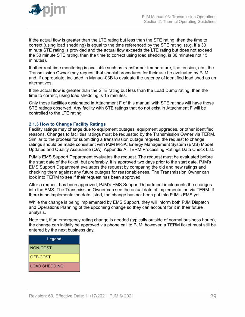
Legend
NON-COST
OFF-COST
LOAD SHEDDING
PJM Manual 03: Transmission OperationsSection 2: Thermal Operating Guidelines
Revision: 60, Effective Date: 11/17/2021 PJM © 2021 29

Thermal Limit Exceeded Corrective Actions Time to Correct
Normal Rating
(Actual flow greater thanNormal Rating but less thanEmergency Rating)
Non-cost actions, off-cost actions,emergency procedures except LoadShed Directive (See Manual M-13,Emergency Procedures).
Within 15 minutes ofexceedance, load shed isnot used.
Emergency Rating
(Actual flow greater thanEmergency Rating but lessthan Load Dump Rating)
All of the above including LoadShed Directive to control flow belowEmergency Rating.
Within 15 minutes ofexceedance
(Note 2)
Load Dump Rating
(Actual flow greater thanLoad Dump Rating)
All of the above including LoadShed Directive to control flow belowEmergency Rating.
Within 5 minutes ofexceedance
(Note 1)
(Note 3)
Exhibit 1: PJM Actual Overload Thermal Operating Policy
Note:1: For unplanned load shed events, TO must initiate load dump action within 5 minutes afterPJM issues a Load Shed Directive. TO must not exceed the time based duration of anyEmergency rating/Load Dump rating.2: TOs have the option of providing STE limits that are at least 30 minutes in duration. The STErating allows the time before load shed to be extended provided the actual flow does not exceedthe STE rating. If the actual flow is above the LTE but below STE, load must be shed within thetimes indicated in Attachment F for the facility, if other corrective actions were not successful.3: A load shed directive will be issued in an amount sufficient to get below Emergency rating.
Thermal LimitExceeded
If Post-Contingency simulated loadingexceeds limit
Time to correct
Normal Trend – continue to monitor. Take non-costactions to prevent contingency from exceedingemergency limit.
N/A
Emergency Use all effective actions and emergencyprocedures except Load Shed Directive
Within 30 minutes
Load Dump All of the above including Load Shed Directive ifanalysis indicates potential for post-contingencycascading.
Within 30 minutes
Exhibit 2: PJM Post-Contingency Simulated Thermal Operating Policy
PJM Manual 03: Transmission OperationsSection 2: Thermal Operating Guidelines
Revision: 60, Effective Date: 11/17/2021 PJM © 2021 30
Note:System readjustment should take place within 30 minutes. PCLLRW should be issued as post-contingency limit exceedance approaches 60 minutes in duration. However, PCLLRW can beissued sooner at the request of the Transmission Owner or if the PJM Dispatcher anticipatescontrolling actions cannot be realized within 60 minutes due to longer generator start-up +notification times.
PJM Manual 03: Transmission OperationsSection 2: Thermal Operating Guidelines
Revision: 60, Effective Date: 11/17/2021 PJM © 2021 31
Section 3: Voltage & Stability Operating GuidelinesWelcome to the Voltage & Stability Operating Guidelines section of the PJM Manual forTransmission Operations. In this section you will find the following information:
• A description of the voltage, voltage related transfer, and stability limits (see “Voltage,Transfer, & Stability Limits”).
• A description of the voltage operation and voltage limits (see “Voltage Operation andVoltage Limits”).
• A description of the voltage control actions for low voltage operation (see “VoltageControl Actions, Low Voltage Operation”).
• A description of the voltage control actions for high voltage operation (see “VoltageControl Actions, High Voltage Operation”).
• How PJM operates capacitors (see “Bulk Electric System Capacitor Operations”).
• A description of the transfer limits (see “Transfer Limits”).
• A description of the stability operation (see “Stability Limits”).
• A description of PJM’s load relief expectations for voltage concerns (see “Load ReliefExpectations”).
• A description of Interconnection Reliability Operating Limits (IROLs).
3.1 Voltage, Transfer, and Stability LimitsIn addition to the thermal limits referenced in Section 2, PJM operates the PJM RTO consideringvoltage and stability related transmission limits as follows:
• Voltage Limits – High, Low, and Load Dump actual voltage limits, High and Lowemergency voltage limits for contingency simulation, and voltage drop limits for widearea transfer simulations to protect against wide area voltage collapse.
• Transfer Limits – The MW flow limitation across an interface to protect the system fromlarge voltage drops or collapse caused by any viable contingency.
• Stability Limits – limit based on voltage phase angle difference to protect portions of thePJM RTO from separation or unstable operation.
3.2 Voltage Operating Criteria and PolicyPJM will operate the facilities that are under PJM’s operational control such that no PJMmonitored facility will violate normal voltage limits on a continuous basis and that no monitoredfacility will violate emergency voltage limits following any simulated facility malfunction or failure.
Typically, high voltage emergency limits are equipment related while low voltage limits aresystem related.
If a limit violation develops, the system is to be returned to within normal continuous voltagelimits and the system is to be returned to within emergency voltage limits for the simulated
PJM Manual 03: Transmission OperationsSection 3: Voltage & Stability Operating Guidelines
Revision: 60, Effective Date: 11/17/2021 PJM © 2021 32
loss of the next most severe contingency consistent with the timelines in the charts below.A 60-minute maximum time is allowed prior to issuing a Post-Contingency Local Load ReliefWarning.
In addition, the post-contingency voltage, resulting from the simulated occurrence of a singlecontingency outage, should not violate any of the following limits:
• Post-contingency simulated voltage lower than the Emergency Low voltage limit, orhigher than the Emergency High voltage limit.
• Post-contingency simulated voltage drop greater than the applicable Voltage Drop limit.
• Post-contingency simulated angular difference greater than the setting of the synchro-check relay less an appropriate safety margin (ten degrees for a 500 kV bus). Theangular difference relates to the ability to reclose transmission lines.
PJM bus voltage limits by voltage level are as shown in Exhibit 3.
PJM operation requires that actions should be taken on a pre-contingency basis in orderto control operations after a malfunction or failure happens. Some examples of possiblepre-contingency actions include pre-arranged approved switching of capacitors or reactors,Phase Angle Regulator tap adjustments (PARs), redispatch, and transaction curtailment. Theseactions can be used pre-contingency to control post-contingency operation so as not to exceedemergency ratings on a simulated basis. These pre-contingency options are considered byPJM for inclusion in the day-ahead analysis. PJM does not have an Under Voltage Load Shedprogram, controlling to voltage limits on a pre-contingency basis in order to avoid load shed.
Voltage Drop Violation limits are utilized to prevent voltage instability, which could result insystem voltage collapse. Voltage Drop Violation limits will be evaluated by PJM based onstudied system voltage characteristics. These limits can vary over a range of values dependingon local transmission system characteristics.
Load dump limits are provided to aid the system operator in identifying the speed necessaryto relieve constraints. Operation at a load dump limit should not result in any facility trippingor voltage collapse when actually operated at that value for at least 15 minutes. In order foran operator to be faced with actual voltages approaching the load dump limit either multiplecontingencies must have occurred or the system had been operated beyond first contingencylimits. PJM will review with each TO the PJM default voltage limits and the appropriateness ofusing individual TO limits based on design and documented past operation.
PJM Manual 03: Transmission OperationsSection 3: Voltage & Stability Operating Guidelines
Revision: 60, Effective Date: 11/17/2021 PJM © 2021 33
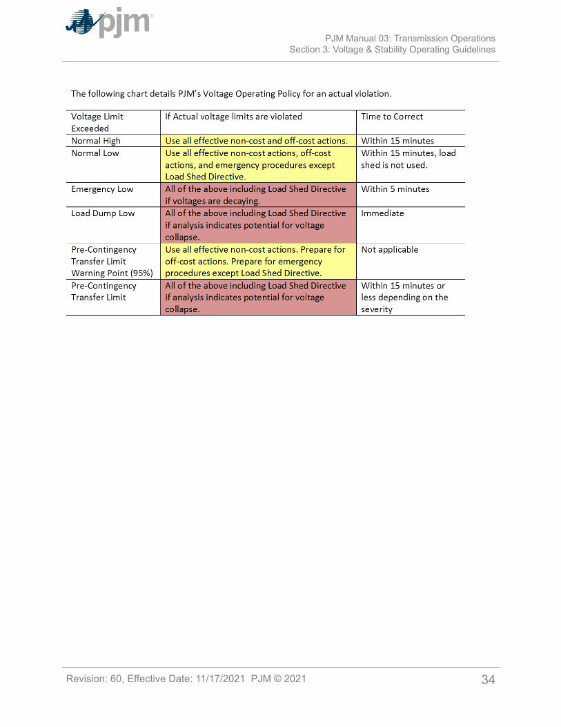
PJM Manual 03: Transmission OperationsSection 3: Voltage & Stability Operating Guidelines
Revision: 60, Effective Date: 11/17/2021 PJM © 2021 34
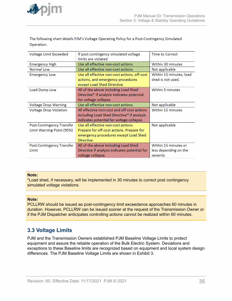
Note:*Load shed, if necessary, will be implemented in 30 minutes to correct post contingencysimulated voltage violations.
Note:PCLLRW should be issued as post-contingency limit exceedance approaches 60 minutes induration. However, PCLLRW can be issued sooner at the request of the Transmission Owner orif the PJM Dispatcher anticipates controlling actions cannot be realized within 60 minutes.
3.3 Voltage LimitsPJM and the Transmission Owners established PJM Baseline Voltage Limits to protectequipment and assure the reliable operation of the Bulk Electric System. Deviations andexceptions to these Baseline limits are recognized based on equipment and local system designdifferences. The PJM Baseline Voltage Limits are shown in Exhibit 3.
PJM Manual 03: Transmission OperationsSection 3: Voltage & Stability Operating Guidelines
Revision: 60, Effective Date: 11/17/2021 PJM © 2021 35
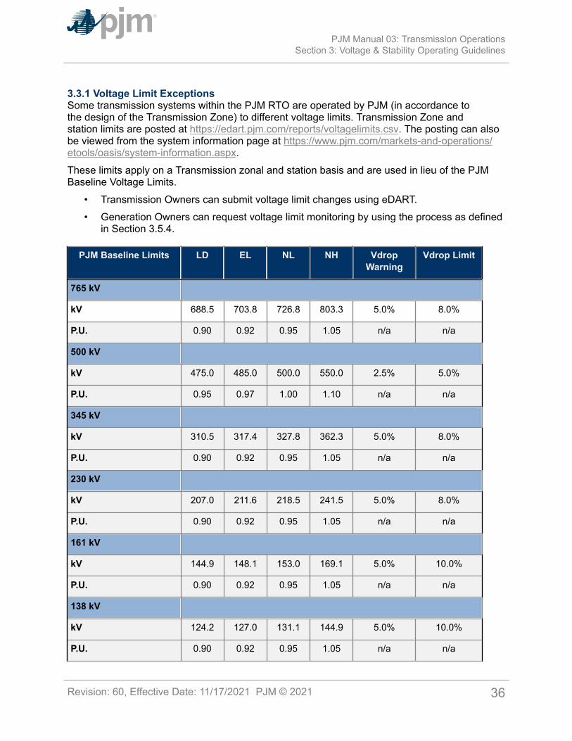
3.3.1 Voltage Limit ExceptionsSome transmission systems within the PJM RTO are operated by PJM (in accordance tothe design of the Transmission Zone) to different voltage limits. Transmission Zone andstation limits are posted at https://edart.pjm.com/reports/voltagelimits.csv. The posting can alsobe viewed from the system information page at https://www.pjm.com/markets-and-operations/etools/oasis/system-information.aspx.These limits apply on a Transmission zonal and station basis and are used in lieu of the PJMBaseline Voltage Limits.
• Transmission Owners can submit voltage limit changes using eDART.• Generation Owners can request voltage limit monitoring by using the process as defined
in Section 3.5.4.
PJM Baseline Limits LD EL NL NH VdropWarning
Vdrop Limit
765 kV
kV 688.5 703.8 726.8 803.3 5.0% 8.0%
P.U. 0.90 0.92 0.95 1.05 n/a n/a
500 kV
kV 475.0 485.0 500.0 550.0 2.5% 5.0%
P.U. 0.95 0.97 1.00 1.10 n/a n/a
345 kV
kV 310.5 317.4 327.8 362.3 5.0% 8.0%
P.U. 0.90 0.92 0.95 1.05 n/a n/a
230 kV
kV 207.0 211.6 218.5 241.5 5.0% 8.0%
P.U. 0.90 0.92 0.95 1.05 n/a n/a
161 kV
kV 144.9 148.1 153.0 169.1 5.0% 10.0%
P.U. 0.90 0.92 0.95 1.05 n/a n/a
138 kV
kV 124.2 127.0 131.1 144.9 5.0% 10.0%
P.U. 0.90 0.92 0.95 1.05 n/a n/a
PJM Manual 03: Transmission OperationsSection 3: Voltage & Stability Operating Guidelines
Revision: 60, Effective Date: 11/17/2021 PJM © 2021 36
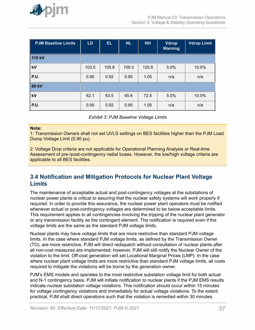
PJM Baseline Limits LD EL NL NH VdropWarning
Vdrop Limit
115 kV
kV 103.5 105.8 109.3 120.8 5.0% 10.0%
P.U. 0.90 0.92 0.95 1.05 n/a n/a
69 kV
kV 62.1 63.5 65.6 72.5 5.0% 10.0%
P.U. 0.90 0.92 0.95 1.05 n/a n/a
Exhibit 3: PJM Baseline Voltage Limits
Note:1: Transmission Owners shall not set UVLS settings on BES facilities higher than the PJM LoadDump Voltage Limit (0.90 pu).
2: Voltage Drop criteria are not applicable for Operational Planning Analysis or Real-timeAssessment of pre-/post-contingency radial buses. However, the low/high voltage criteria areapplicable to all BES facilities.
3.4 Notification and Mitigation Protocols for Nuclear Plant VoltageLimitsThe maintenance of acceptable actual and post-contingency voltages at the substations ofnuclear power plants is critical to assuring that the nuclear safety systems will work properly ifrequired. In order to provide this assurance, the nuclear power plant operators must be notifiedwhenever actual or post-contingency voltages are determined to be below acceptable limits.This requirement applies to all contingencies involving the tripping of the nuclear plant generatoror any transmission facility as the contingent element. The notification is required even if thevoltage limits are the same as the standard PJM voltage limits.
Nuclear plants may have voltage limits that are more restrictive than standard PJM voltagelimits. In the case where standard PJM voltage limits, as defined by the Transmission Owner(TO), are more restrictive, PJM will direct redispatch without consultation of nuclear plants afterall non-cost measures are implemented; however, PJM will still notify the Nuclear Owner of theviolation to the limit. Off-cost generation will set Locational Marginal Prices (LMP). In the casewhere nuclear plant voltage limits are more restrictive than standard PJM voltage limits, all costsrequired to mitigate the violations will be borne by the generation owner.
PJM’s EMS models and operates to the most restrictive substation voltage limit for both actualand N-1 contingency basis. PJM will initiate notification to nuclear plants if the PJM EMS resultsindicate nuclear substation voltage violations. This notification should occur within 15 minutesfor voltage contingency violations and immediately for actual voltage violations. To the extentpractical, PJM shall direct operations such that the violation is remedied within 30 minutes.
PJM Manual 03: Transmission OperationsSection 3: Voltage & Stability Operating Guidelines
Revision: 60, Effective Date: 11/17/2021 PJM © 2021 37
3.4.1 CommunicationAll communication of future and current operations between PJM and the nuclear plant shouldbe through the Transmission Owner (TO). If there is any confusion about a communication,the plant can talk directly with PJM, however, the Transmission Owner should be appraised ofthe discussion – if PJM to a nuclear plant direct discussions are needed the preferred methodwould be a 3-way call among all parties (i.e., inclusion of TO). If off-cost operations are requiredbased on a more restrictive Nuclear Plant voltage limit, the Nuclear Plant or their representative(Nuclear Duty Officer) may consult with the related MOC and evaluate whether an alternativesuch as operating at a reduced output would alleviate the voltage violation and is more costeffective. PJM will provide the approximate nuclear plant reduction, if applicable.
3.4.2 Information ExchangeNormally, PJM does not provide information relative to transmission operation to any individualMarket participant without providing that information to all. However, in this unique conditionwhere the public safety requirement is to have a reliable source for safe unit shutdown and/oraccident mitigation; it is imperative that specific information be provided to a nuclear plant (thisinformation should not be provided to their marketing members). If PJM operators observevoltage violations or anticipate voltage violations (pre or post-contingency) at any nuclearstations; PJM operators are permitted to provide the nuclear plant with the actual voltage at thatlocation, the post-contingency voltage at that location (if appropriate) and limiting contingencycausing the violation. The operation for more restrictive Nuclear Plant Voltage Limits at thesenuclear stations should not be posted or provided to the Market via Data Viewer, once off-costoperations are initiated.
PJM Actions:• PJM notifies nuclear plant, through Transmission Owner, of calculated post-contingency
violations to modeled voltage limits (Transmission Owner or more limiting Nuclear PlantVoltage Limits).
• PJM notify nuclear plant, through Transmission Owner, of violations to actual voltagelimits (Transmission Owner or more limiting Nuclear Plant Voltage Limits).
• Violations of more restrictive Nuclear Plant Voltage Limits must be agreed upon by thenuclear plant and logged by PJM.
• All non-cost actions should be implemented prior to MW adjustments.• All costs required to mitigate violations of more restrictive Nuclear Plant Voltage Limits
will be borne by the generation owner.• Controlling actions must be cost-capped, if applicable.• LMP shall not be used to control the voltage at these locations.• TLR shall not be used to control the voltage at these locations.• PJM will monitor the appropriate voltage limits based on changes provided.• PJM notify nuclear plant, through Transmission Owner, when voltage level is restored
within limits (and stable).• Attempt to control more restrictive nuclear plant voltage limitations within 30 minutes.
PJM Manual 03: Transmission OperationsSection 3: Voltage & Stability Operating Guidelines
Revision: 60, Effective Date: 11/17/2021 PJM © 2021 38
Transmission Owner Actions:• The Transmission Owner shall independently monitor for Nuclear Plant actual and
contingency voltage violations as reflected on the Transmission System.• Transmission Owner will communicate this notification from PJM to the nuclear plant
(Transmission Owner or more limiting Nuclear Plant Voltage Limit violations).• Transmission Owners will monitor the appropriate voltage limits based on changes to
more limiting Nuclear Plant Voltage Limits as provided by the Nuclear Duty Officer(NDO).
Nuclear Plant Actions:• Nuclear plant will notify PJM, through Transmission Owner Shift Managers, when
different (new or default) voltage limits shall be used based on various plant serviceloading conditions, design basis calculation revisions.
• Determine internal plant options, and if appropriate, provide revised limits.o NOTE: Revised Nuclear Voltage Limits will also be communicated through eDART’s
Nuclear Voltage Limit feature, a zero MW ticket, or M-03 Attachment C.• Coordinate with MOC to evaluate PJM provided redispatch option (no cost or unit
information will be provided).• Provide PJM with decision to redispatch – if applicable.• Provide PJM with decision that nuclear plant will closely monitor plant activities and
will take action within the plant if conditions change and inform PJM not to implementoff-cost.
• Provide PJM with clear direction if they do not want PJM to perform redispatch.
Note:PJM dispatch’s goal is to resolve all voltage security violations (i.e., N-1 contingency) within30 minutes, however; inherent communication delays related to off-cost agreement for nuclearplant voltage limits may not permit this goal to be achieved.
3.5 Voltage Control ActionsPJM is responsible for the overall coordination of the Bulk Electric System voltage scheduling.In general, since voltage schedules have a significant effect on local voltages PJM authorizesthe Local Transmission Control Center to establish and adjust generator voltage schedulesafter gaining PJM approval. Whenever the voltage schedule impacts the overall PJM economic/reliable operation, PJM shall exercise its operational control and direct changes to thegeneration voltage/reactive schedules, capacitor/reactor schedule/status, and transformer LTCoperation for the overall reliable/economic operation of PJM.
• PJM requires that automatic capacitor switching capability on facilities 230 kV and abovebe documented in Section 3 of this manual. PJM authorizes the Local TransmissionControl Center to automatically or manually switch/adjust reactive devices connecting to138 kV and below without notifying PJM. Transmission Owners shall evaluate the impact
PJM Manual 03: Transmission OperationsSection 3: Voltage & Stability Operating Guidelines
Revision: 60, Effective Date: 11/17/2021 PJM © 2021 39
of switching BES capacitor/reactors or adjusting BES LTC on voltage limits and lagging/leading MVAR reserves. The evaluation may require use of EMS Security Analysisor other analysis packages depending on system conditions and proximity to limits.Transmission Owners shall request PJM to study the impact of switching capacitor/reactors or LTC adjustments if the TO determines they are unable to analyze the impacton SOL related equipment.
• When deviating from the generator voltage schedule the Transmission Owner shallcoordinate with the PJM dispatcher so that PJM can determine if the change isdetrimental to PJM reliable/economic operation.
• When PJM requests to change voltage or VAR schedule, PJM should discuss thechanges with the Transmission Owner and if the recommendation does not cause adefined limitation the Transmission Owner should implement the PJM request. PJM hasoperational control of the reactive facilities (transmission caps, LTC's, and generatorregulation). If internal plant limits (or Transmission Owner local limits) restrict the requestthey should be logged so that PJM can investigate and recommend changes to plantfacilities if appropriate.
• Generation Owners that possess generation resources equipped with Power SystemStabilizers are required to communicate PSS status to the appropriate TransmissionOwner as well as to PJM via the eDART outage reporting system.
3.5.1 EHV Transformer LTC OperationThe PJM dispatcher has operational control of and coordinates the operation of the EHVLTC transformer taps. In general, EHV LTC transformer tap changers are not operated underautomatic voltage control but are operated in coordination with all other Bulk Electric Systemvoltage control facilities.Operation of the PJM RTO is coordinated in an attempt to minimize capacitor switchingoperation and transformer tap changes. PJM coordinates with the Local Control Centers, allswitching of the Bulk Electric System capacitors & reactors to assist the system for actual orpost-contingency situations. Local conditions may require some deviations.
3.5.2 Voltage Control Options for Non-Tariff FacilitiesOn occasion, PJM is requested to dispatch generation to protect PJM member equipment/facilities where that equipment is not included in the PJM tariff, and therefore notaccommodated by standard PJM redispatch. PJM will accommodate requests for schedulingand dispatching off-cost generation. In the examples below, PJM describes conditions wherecharging for off-cost generation may result.Off-cost examples:
• If requested to run generation for a distribution related problem PJM will accommodatea member’s request for “off-cost” operation. Appropriate billing will be made to therequestor. [A PJM Transmission Owner may request limits to PJM OATT facilities toprotect their distribution system reliability (non-PJM OATT facilities). PJM will bill thePJM Member for any resulting off-cost operation.]
PJM Manual 03: Transmission OperationsSection 3: Voltage & Stability Operating Guidelines
Revision: 60, Effective Date: 11/17/2021 PJM © 2021 40
• If requested to run generation to protect a generating station or other non-tarifffacility, PJM can accommodate a PJM member’s request for the “off-cost” generationassignment. PJM will bill the PJM Member for any resulting off-cost operation.
• If requested to run generation for a Transmission Owner determined non-PJM reliabilitylimit, PJM will accommodate that member’s request for “off-cost” operation. Appropriatebilling will be made to the requestor.
As an alternative to PJM directed off-cost generation, the requestor could enter into anagreement with any generation provider; this agreement would be treated independent fromthe PJM billing process.
3.5.3 Bulk Electric System Capacitor/SVC OperationThe PJM dispatcher coordinates the operation of Bulk Electric System capacitors. Capacitorsshould be kept in service whenever they are beneficial to the PJM RTO transfer capability orreliability.
Note:The capacitor banks at each installation operate independently of each other under normalswitching operations. Under normal conditions, the PJM dispatcher does not request that bothbanks of capacitors at one location be brought on or off simultaneously; generally at least fiveminutes between switching is desirable. The PJM dispatcher monitors the system voltage profileand the transfer capability of the PJM RTO and requests capacitor switching or transformer tapchanges in a timely manner.
Operation of the PJM RTO is coordinated in an attempt to minimize capacitor switchingoperation and transformer tap changes. PJM coordinates with the Local Control Centers, allswitching of the 230 kV and 500 kV capacitors and variable reactors to assist the system foractual or post-contingency situations. Local conditions may require some deviations. The 500kV LTC transformer taps should be adjusted to control the system voltage regardless of thecapacitor's in or out-of-service status. A bank of capacitors should not be switched in-service ifthe voltage on the bus, upon which it is located, would violate voltage limits.The PJM RTO maximum voltage limits should not be exceeded on an actual or simulated post-contingency basis. As the PJM RTO voltage approaches limits, the PJM dispatcher analyzesand estimates the future system voltages and decides if there will be a need to remove anyor all capacitors from service. The PJM dispatcher arranges to remove capacitors from serviceprior to the PJM RTO voltage reaching the maximum limits.If PJM’s simulated post-contingency analysis or a Transmission Owner’s real-time monitoringprogram detects that the first contingency loss of a facility results in a Bulk Electric System busexceeding its Emergency High limit, the PJM dispatcher evaluates the removal of any or allcapacitors at that bus from service as necessary.Prior to expected light-load periods, capacitors should be switched out-of-service beforereaching limits if the PJM dispatcher expects that the switching operation is required in thefuture.
• ACE’s 230 kV capacitor bank at Dennis is under automatic control of Dennis SVC and230 kV capacitor bank at Cardiff is under automatic control of Cardiff SVC.
PJM Manual 03: Transmission OperationsSection 3: Voltage & Stability Operating Guidelines
Revision: 60, Effective Date: 11/17/2021 PJM © 2021 41
• DPL’s 230 kV capacitor bank at Indian River is under automatic control of Indian RiverSVC.
• First Energy South 500 kV switched capacitor banks at the Black Oak Substation are allunder automatic control of the Black Oak Static Var compensator (SVC).
• First Energy South 230 kV switched capacitor bank #3 at the Shingletown will beswitched automatically in and out of service depending on the Shingletown 230 kVbus voltage. Automatic switching in-service will be initiated when the Shingletown busvoltage is at 228.8 kV and switched out-of-service when the Shingletown bus voltage isat 239.2 kV.
• First Energy South 230 kV switched capacitor bank #2 at Montgomery will be switchedautomatically in and out of service depending on the Montgomery 230 kV bus voltage.Automatic switching in-service will be initiated when the Montgomery bus voltage is at225 kV and switched out-of-service when the Montgomery bus voltage is at 236 kV.
• First Energy South 230 kV switched capacitor bank at Damascus will be switchedautomatically in and out of service depending on the Damascus 230 kV bus voltage.Automatic switching in-service will be initiated when the Damascus bus voltage is at220.8 kV and switched out-of-service when the Damascus bus voltage is at 234.6 kV.
• First Energy South 500 kV switched capacitor bank at the Meadow Brook Substation isunder automatic control of the Meadow Brook Static Var compensator (SVC).
• First Energy East (JC) 230 kV capacitor banks at the Atlantic and Larrabee Substationsare all under automatic control of the Atlantic Static Var Compensator (SVC).
• First Energy East (JC) 230 kV capacitor banks at the West Wharton Substation are allunder automatic control of the West Wharton Static Var Compensator (SVC).
• First Energy East (PN) 500 kV capacitor banks at the Hunterstown Substation are underautomatic control of the Hunterstown Static Var Compensator (SVC).
• First Energy East (PN) 230 kV capacitor banks at the Altoona Substation are underautomatic control of the Altoona Static Var Compensator (SVC).
• First Energy East (PN) 230 kV capacitor banks at the Erie South and Four MileSubstations are under automatic control of the Erie South Static Var Compensator(SVC).
The following capacitor installations are equipped with Programmable Logic Controllers (PLCs)or under SVC’s logic control and are the first automatically switchable 500 kV capacitors on thePJM RTO EHV system:
Capacitor Installation Banks
Juniata 2-250 MVAR Banks
Conemaugh 2-200 MVAR Bank
Conastone 1-200 MVAR Bank
Limerick 1-200 MVAR Bank
PJM Manual 03: Transmission OperationsSection 3: Voltage & Stability Operating Guidelines
Revision: 60, Effective Date: 11/17/2021 PJM © 2021 42
Capacitor Installation Banks
Hunterstown* 1-100 MVAR Bank
Exhibit 4: Capacitor Installations with PLCs
* Under normal operating conditions capacitor bank(s) is/are under the SVC logic control.
To improve system voltages, the PJM dispatcher may switch capacitors with PLCs in serviceprior to switching in service non-PLC capacitors in other areas.PLC initiated switching is limited to a basic voltage scheme:
• Capacitor automatic tripping generally is set to occur as follows:o Voltage above 555 kV – 15 seconds.o Voltage at 555-550 kV – 15 to 60 seconds.o Voltage at 550-545 kV – 1 to 15 minutes.o Voltage at 545 kV – 15 minutes.
• Capacitor automatic closing generally is set to occur as follows:o Voltage below 470 kV – 1 second.o Voltage at 475-470 kV – 1 to 15 seconds.o Voltage at 500-475 kV – 15 to 60 seconds.o Voltage at 510-500 kV – 1 to 15 minutes.o Voltage at 510 kV – 15 minutes.
• Juniata 500 kV Capacitors – Both capacitors are in the AUTO mode of operation. Thevoltage controlled operations are enabled for the capacitors in AUTO mode.
• Elroy 500 kV Capacitors - Two 300 MVAR capacitors (600 MVAR total) are located atElroy 500 kV substation. Control systems have been set to have the first 300 MVAR ofcapacitors on system within 10 cycles from the beginning of the voltage collapse with thesecond 300 MVAR of capacitors on system 20 cycles from the beginning of the systemevent. Automatic switching will initiate when a 5% voltage reduction on all three phasesover a 5 cycle time period occurs, resulting in the closure of the first cap bank CB (notime delay). 10 cycles after the first initiate the SEL 451 will initiate closure of the secondcap bank CB.
• The LSR Auto/Manual 43 Control Switch, located on Elroy control panel #1, SHALLbe placed in the manual position via EMS to disarm the auto scheme for the followingconditions:o Maintenance outages at Elroy including Elroy 500 kV #2 Bus, 20-1 capacitor, 22-1
capacitor, 155 CB, or 175 CB.o PJM issues a High System Voltage Action.
• When PJM cancels the High System Voltage Action, the Elroy capacitors are to beplaced in the auto position.
PJM Manual 03: Transmission OperationsSection 3: Voltage & Stability Operating Guidelines
Revision: 60, Effective Date: 11/17/2021 PJM © 2021 43
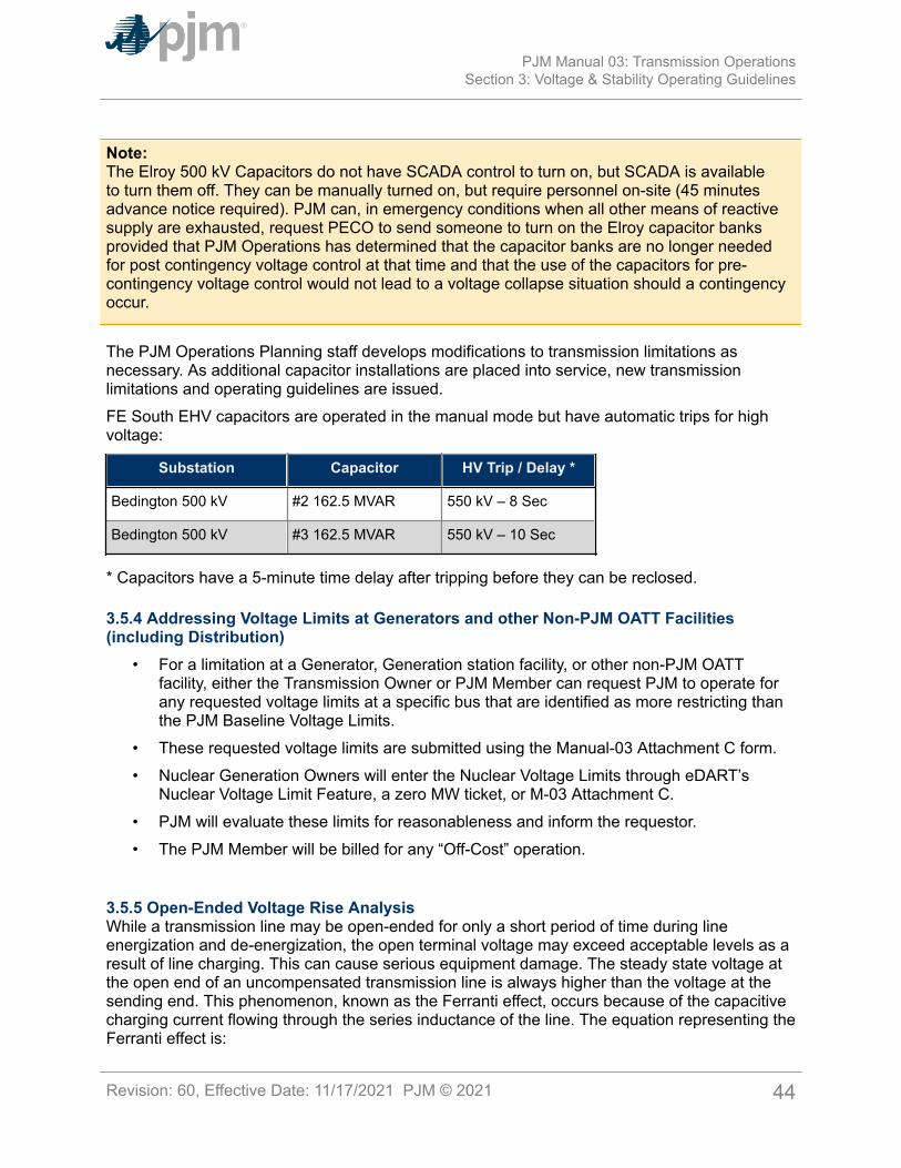
Note:The Elroy 500 kV Capacitors do not have SCADA control to turn on, but SCADA is availableto turn them off. They can be manually turned on, but require personnel on-site (45 minutesadvance notice required). PJM can, in emergency conditions when all other means of reactivesupply are exhausted, request PECO to send someone to turn on the Elroy capacitor banksprovided that PJM Operations has determined that the capacitor banks are no longer neededfor post contingency voltage control at that time and that the use of the capacitors for pre-contingency voltage control would not lead to a voltage collapse situation should a contingencyoccur.
The PJM Operations Planning staff develops modifications to transmission limitations asnecessary. As additional capacitor installations are placed into service, new transmissionlimitations and operating guidelines are issued.FE South EHV capacitors are operated in the manual mode but have automatic trips for highvoltage:
Substation Capacitor HV Trip / Delay *
Bedington 500 kV #2 162.5 MVAR 550 kV – 8 Sec
Bedington 500 kV #3 162.5 MVAR 550 kV – 10 Sec
* Capacitors have a 5-minute time delay after tripping before they can be reclosed.
3.5.4 Addressing Voltage Limits at Generators and other Non-PJM OATT Facilities(including Distribution)
• For a limitation at a Generator, Generation station facility, or other non-PJM OATTfacility, either the Transmission Owner or PJM Member can request PJM to operate forany requested voltage limits at a specific bus that are identified as more restricting thanthe PJM Baseline Voltage Limits.
• These requested voltage limits are submitted using the Manual-03 Attachment C form.• Nuclear Generation Owners will enter the Nuclear Voltage Limits through eDART’s
Nuclear Voltage Limit Feature, a zero MW ticket, or M-03 Attachment C.• PJM will evaluate these limits for reasonableness and inform the requestor.• The PJM Member will be billed for any “Off-Cost” operation.
3.5.5 Open-Ended Voltage Rise AnalysisWhile a transmission line may be open-ended for only a short period of time during lineenergization and de-energization, the open terminal voltage may exceed acceptable levels as aresult of line charging. This can cause serious equipment damage. The steady state voltage atthe open end of an uncompensated transmission line is always higher than the voltage at thesending end. This phenomenon, known as the Ferranti effect, occurs because of the capacitivecharging current flowing through the series inductance of the line. The equation representing theFerranti effect is:
PJM Manual 03: Transmission OperationsSection 3: Voltage & Stability Operating Guidelines
Revision: 60, Effective Date: 11/17/2021 PJM © 2021 44
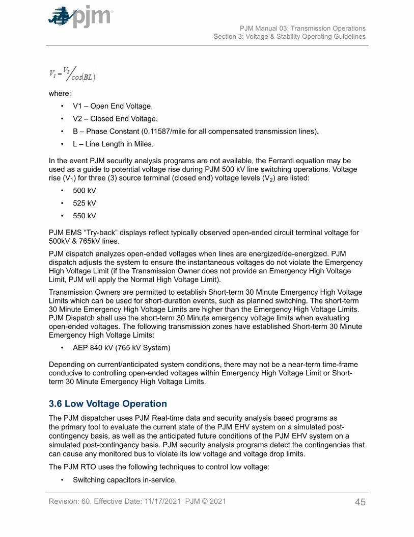
where:• V1 – Open End Voltage.• V2 – Closed End Voltage.• B – Phase Constant (0.11587/mile for all compensated transmission lines).• L – Line Length in Miles.
In the event PJM security analysis programs are not available, the Ferranti equation may beused as a guide to potential voltage rise during PJM 500 kV line switching operations. Voltagerise (V1) for three (3) source terminal (closed end) voltage levels (V2) are listed:
• 500 kV• 525 kV• 550 kV
PJM EMS “Try-back” displays reflect typically observed open-ended circuit terminal voltage for500kV & 765kV lines.PJM dispatch analyzes open-ended voltages when lines are energized/de-energized. PJMdispatch adjusts the system to ensure the instantaneous voltages do not violate the EmergencyHigh Voltage Limit (if the Transmission Owner does not provide an Emergency High VoltageLimit, PJM will apply the Normal High Voltage Limit).Transmission Owners are permitted to establish Short-term 30 Minute Emergency High VoltageLimits which can be used for short-duration events, such as planned switching. The short-term30 Minute Emergency High Voltage Limits are higher than the Emergency High Voltage Limits.PJM Dispatch shall use the short-term 30 Minute emergency voltage limits when evaluatingopen-ended voltages. The following transmission zones have established Short-term 30 MinuteEmergency High Voltage Limits:
• AEP 840 kV (765 kV System)
Depending on current/anticipated system conditions, there may not be a near-term time-frameconducive to controlling open-ended voltages within Emergency High Voltage Limit or Short-term 30 Minute Emergency High Voltage Limits.
3.6 Low Voltage OperationThe PJM dispatcher uses PJM Real-time data and security analysis based programs asthe primary tool to evaluate the current state of the PJM EHV system on a simulated post-contingency basis, as well as the anticipated future conditions of the PJM EHV system on asimulated post-contingency basis. PJM security analysis programs detect the contingencies thatcan cause any monitored bus to violate its low voltage and voltage drop limits.
The PJM RTO uses the following techniques to control low voltage:
• Switching capacitors in-service.
PJM Manual 03: Transmission OperationsSection 3: Voltage & Stability Operating Guidelines
Revision: 60, Effective Date: 11/17/2021 PJM © 2021 45
• Switching reactors out-of-service.
• Adjust variable reactor tap positions.
• Adjusting voltage set point of static VAR compensators (SVC).
• Operating synchronous condensers.
• Changing transformer tap positions.
• Changing generation excitation.
• Adjusting generation MW output (i.e., to change line flows).
• Adjusting transactions.
• Adjusting PARs.
• Switching transmission facilities in/out of service.
The PJM Baseline Voltage Limits (see Exhibit 3) and how they would be applied to reliablesystem operation is:
• PJM will use the “PJM Baseline Voltage Limits” as the default “PJM Voltage ReliabilityOperating Limit”. If a PJM Transmission Owner identifies a specific voltage reliabilitylimit, PJM will assess and use, if approved, that voltage reliability limit provided by theTransmission Owner as the PJM Voltage Reliability Operating Limit. However, the usewill depend on the condition that the facility is specifically identified as a PJM OpenAccess Transmission Tariff (“PJM OATT”) facility, and the limit is specifically identified asrequired for reliable operation.
• The PJM Voltage Reliability Operating Limit will be either the PJM Baseline Voltage Limitor the Transmission Owner provided voltage reliability limit.
• PJM does not charge or bill a PJM Transmission Owner for off-cost operation ofa PJM OATT facility as described above. In addition, these PJM Voltage ReliabilityOperating Limits will be used in PJM System Planning reinforcement evaluations. PJMshall evaluate the need to upgrade any restricting facility and study the validity of thatreliability limit.
3.7 High Voltage OperationThe PJM dispatcher uses PJM Real-time data and security analysis based programs asthe primary tool to evaluate the current state of the PJM EHV system on a simulated post-contingency basis, as well as the anticipated future conditions of the PJM EHV system on asimulated post-contingency basis. PJM security analysis programs detect the contingencies thatcan cause any monitored bus to violate its high voltage limits.
The PJM RTO uses the following techniques to control high voltage:
• Switching capacitors out-of-service.
• Switching reactors in-service.
• Adjust variable reactor tap positions.
• Adjusting voltage set point of Static Var Compensators (SVC).
PJM Manual 03: Transmission OperationsSection 3: Voltage & Stability Operating Guidelines
Revision: 60, Effective Date: 11/17/2021 PJM © 2021 46
• Adjusting voltage set point of Static Synchronous Compensators (STATCOM).
• Operating synchronous condensers.
• Changing transformer tap positions.
• Changing generation excitation.
• Adjusting generation MW output (i.e., to change line flows) for actual voltage violationsonly.
• Adjusting PARs.
• Switching transmission facilities in/out of service.
PJM performs the following actions to correct high voltage conditions (see PJM M-13:Emergency Operations, Section 2.4.7 for additional Real-time emergency actions):
• The PJM dispatcher requests that switchable capacitors be disconnected and switchablereactors be connected.
• The PJM dispatcher requests Local Control Center operators to direct all generators,synchronous condensers and SVCs within their zone to absorb reactive power.
• The PJM dispatcher requests neighboring Balancing Authorities to assist in reducingvoltage.
• The PJM dispatcher directs the adjustment 500/230 kV transformer taps to optimizesystem voltage. Adjustment of transformer taps will be coordinated and agreed tobetween PJM and the Transmission Owner before changes are made. The greatesteffect to control system voltage is attained by adjusting all 500/230 kV transformer taps.
• The PJM dispatcher requests the Transmission Owners to open approved and effectiveEHV circuits. The PJM dispatcher performs the following tasks:
o Verifies thermal conditions with on-line study programs.
o Uses computer programs to study the simulated effects of switching and the steadystate voltage response.
o Directs operation to open both terminals by the TO (open the terminal without acontrolling source or the highest voltage bus first).
Opening Lines for Voltage ControlWhen high voltage conditions are expected on the PJM RTO, the PJM dispatcher uses PJMSecurity Analysis programs to study possible actions (i.e., opening high voltage line) andcoordinates an operational plan before the situation becomes severe. If system voltages gettoo high, it may be difficult (if not impossible) to remove a line from service due to the voltagerise experienced at the open end of the circuit being removed from service. Corrective actionshave a maximum effect only when they are accomplished prior to experiencing the problem.During high voltage conditions, opening high voltage circuit has a positive effect in reducingsystem voltages for two reasons:
• It increases losses on the rest of the PJM EHV system.• It eliminates the capacitive charging of the line.
PJM Manual 03: Transmission OperationsSection 3: Voltage & Stability Operating Guidelines
Revision: 60, Effective Date: 11/17/2021 PJM © 2021 47
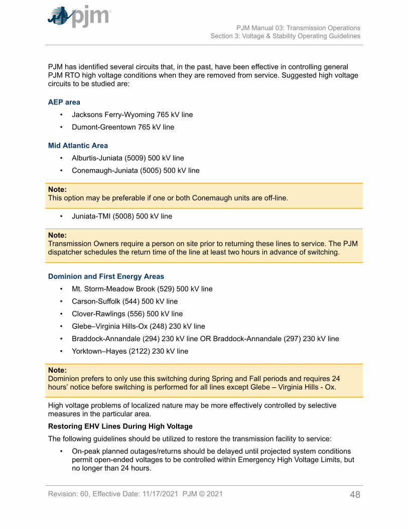
PJM has identified several circuits that, in the past, have been effective in controlling generalPJM RTO high voltage conditions when they are removed from service. Suggested high voltagecircuits to be studied are:
AEP area• Jacksons Ferry-Wyoming 765 kV line• Dumont-Greentown 765 kV line
Mid Atlantic Area• Alburtis-Juniata (5009) 500 kV line• Conemaugh-Juniata (5005) 500 kV line
Note:This option may be preferable if one or both Conemaugh units are off-line.
• Juniata-TMI (5008) 500 kV line
Note:Transmission Owners require a person on site prior to returning these lines to service. The PJMdispatcher schedules the return time of the line at least two hours in advance of switching.
Dominion and First Energy Areas• Mt. Storm-Meadow Brook (529) 500 kV line• Carson-Suffolk (544) 500 kV line• Clover-Rawlings (556) 500 kV line• Glebe–Virginia Hills-Ox (248) 230 kV line• Braddock-Annandale (294) 230 kV line OR Braddock-Annandale (297) 230 kV line• Yorktown–Hayes (2122) 230 kV line
Note:Dominion prefers to only use this switching during Spring and Fall periods and requires 24hours’ notice before switching is performed for all lines except Glebe – Virginia Hills - Ox.
High voltage problems of localized nature may be more effectively controlled by selectivemeasures in the particular area.Restoring EHV Lines During High VoltageThe following guidelines should be utilized to restore the transmission facility to service:
• On-peak planned outages/returns should be delayed until projected system conditionspermit open-ended voltages to be controlled within Emergency High Voltage Limits, butno longer than 24 hours.
PJM Manual 03: Transmission OperationsSection 3: Voltage & Stability Operating Guidelines
Revision: 60, Effective Date: 11/17/2021 PJM © 2021 48
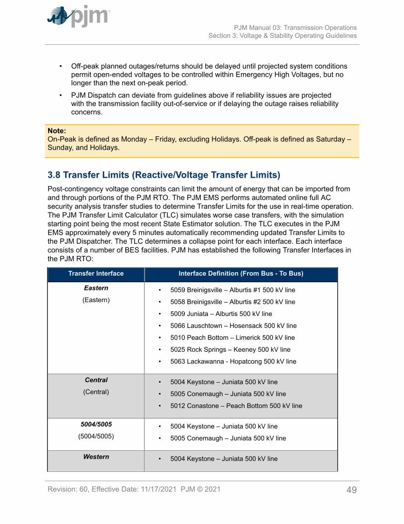
• Off-peak planned outages/returns should be delayed until projected system conditionspermit open-ended voltages to be controlled within Emergency High Voltages, but nolonger than the next on-peak period.
• PJM Dispatch can deviate from guidelines above if reliability issues are projectedwith the transmission facility out-of-service or if delaying the outage raises reliabilityconcerns.
Note:On-Peak is defined as Monday – Friday, excluding Holidays. Off-peak is defined as Saturday –Sunday, and Holidays.
3.8 Transfer Limits (Reactive/Voltage Transfer Limits)Post-contingency voltage constraints can limit the amount of energy that can be imported fromand through portions of the PJM RTO. The PJM EMS performs automated online full ACsecurity analysis transfer studies to determine Transfer Limits for the use in real-time operation.The PJM Transfer Limit Calculator (TLC) simulates worse case transfers, with the simulationstarting point being the most recent State Estimator solution. The TLC executes in the PJMEMS approximately every 5 minutes automatically recommending updated Transfer Limits tothe PJM Dispatcher. The TLC determines a collapse point for each interface. Each interfaceconsists of a number of BES facilities. PJM has established the following Transfer Interfaces inthe PJM RTO:
Transfer Interface Interface Definition (From Bus - To Bus)
Eastern
(Eastern)• 5059 Breinigsville – Alburtis #1 500 kV line
• 5058 Breinigsville – Alburtis #2 500 kV line
• 5009 Juniata – Alburtis 500 kV line
• 5066 Lauschtown – Hosensack 500 kV line
• 5010 Peach Bottom – Limerick 500 kV line
• 5025 Rock Springs – Keeney 500 kV line
• 5063 Lackawanna - Hopatcong 500 kV line
Central
(Central)• 5004 Keystone – Juniata 500 kV line
• 5005 Conemaugh – Juniata 500 kV line
• 5012 Conastone – Peach Bottom 500 kV line
5004/5005
(5004/5005)• 5004 Keystone – Juniata 500 kV line
• 5005 Conemaugh – Juniata 500 kV line
Western • 5004 Keystone – Juniata 500 kV line
PJM Manual 03: Transmission OperationsSection 3: Voltage & Stability Operating Guidelines
Revision: 60, Effective Date: 11/17/2021 PJM © 2021 49
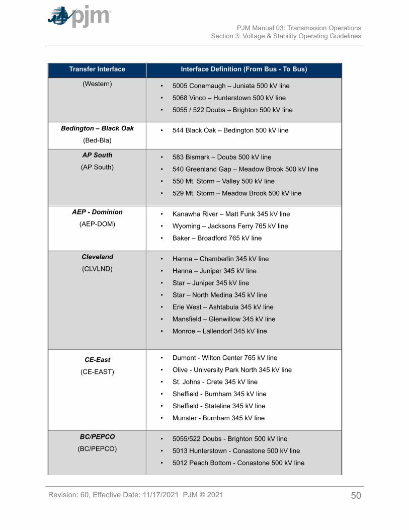
Transfer Interface Interface Definition (From Bus - To Bus)
(Western) • 5005 Conemaugh – Juniata 500 kV line
• 5068 Vinco – Hunterstown 500 kV line
• 5055 / 522 Doubs – Brighton 500 kV line
Bedington – Black Oak
(Bed-Bla)• 544 Black Oak – Bedington 500 kV line
AP South
(AP South)• 583 Bismark – Doubs 500 kV line
• 540 Greenland Gap – Meadow Brook 500 kV line
• 550 Mt. Storm – Valley 500 kV line
• 529 Mt. Storm – Meadow Brook 500 kV line
AEP - Dominion
(AEP-DOM)• Kanawha River – Matt Funk 345 kV line
• Wyoming – Jacksons Ferry 765 kV line
• Baker – Broadford 765 kV line
Cleveland
(CLVLND)• Hanna – Chamberlin 345 kV line
• Hanna – Juniper 345 kV line
• Star – Juniper 345 kV line
• Star – North Medina 345 kV line
• Erie West – Ashtabula 345 kV line
• Mansfield – Glenwillow 345 kV line
• Monroe – Lallendorf 345 kV line
CE-East
(CE-EAST)
• Dumont - Wilton Center 765 kV line
• Olive - University Park North 345 kV line
• St. Johns - Crete 345 kV line
• Sheffield - Burnham 345 kV line
• Sheffield - Stateline 345 kV line
• Munster - Burnham 345 kV line
BC/PEPCO
(BC/PEPCO)• 5055/522 Doubs - Brighton 500 kV line
• 5013 Hunterstown - Conastone 500 kV line
• 5012 Peach Bottom - Conastone 500 kV line
PJM Manual 03: Transmission OperationsSection 3: Voltage & Stability Operating Guidelines
Revision: 60, Effective Date: 11/17/2021 PJM © 2021 50
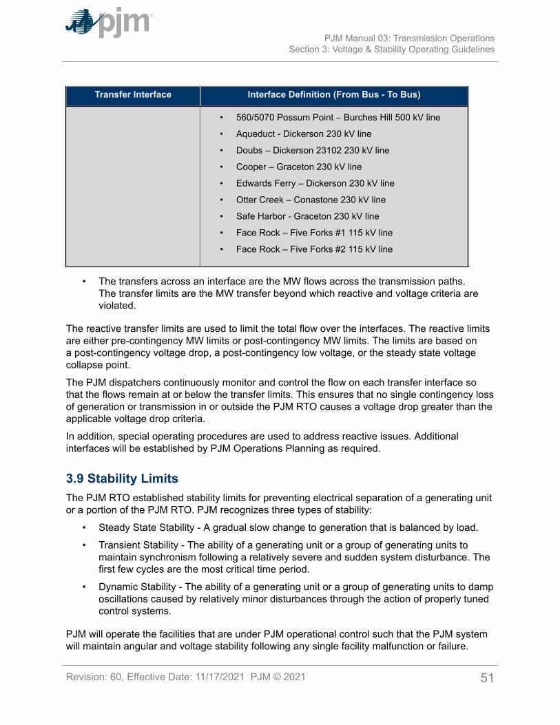
Transfer Interface Interface Definition (From Bus - To Bus)
• 560/5070 Possum Point – Burches Hill 500 kV line
• Aqueduct - Dickerson 230 kV line
• Doubs – Dickerson 23102 230 kV line
• Cooper – Graceton 230 kV line
• Edwards Ferry – Dickerson 230 kV line
• Otter Creek – Conastone 230 kV line
• Safe Harbor - Graceton 230 kV line
• Face Rock – Five Forks #1 115 kV line
• Face Rock – Five Forks #2 115 kV line
• The transfers across an interface are the MW flows across the transmission paths.The transfer limits are the MW transfer beyond which reactive and voltage criteria areviolated.
The reactive transfer limits are used to limit the total flow over the interfaces. The reactive limitsare either pre-contingency MW limits or post-contingency MW limits. The limits are based ona post-contingency voltage drop, a post-contingency low voltage, or the steady state voltagecollapse point.
The PJM dispatchers continuously monitor and control the flow on each transfer interface sothat the flows remain at or below the transfer limits. This ensures that no single contingency lossof generation or transmission in or outside the PJM RTO causes a voltage drop greater than theapplicable voltage drop criteria.
In addition, special operating procedures are used to address reactive issues. Additionalinterfaces will be established by PJM Operations Planning as required.
3.9 Stability LimitsThe PJM RTO established stability limits for preventing electrical separation of a generating unitor a portion of the PJM RTO. PJM recognizes three types of stability:
• Steady State Stability - A gradual slow change to generation that is balanced by load.
• Transient Stability - The ability of a generating unit or a group of generating units tomaintain synchronism following a relatively severe and sudden system disturbance. Thefirst few cycles are the most critical time period.
• Dynamic Stability - The ability of a generating unit or a group of generating units to damposcillations caused by relatively minor disturbances through the action of properly tunedcontrol systems.
PJM will operate the facilities that are under PJM operational control such that the PJM systemwill maintain angular and voltage stability following any single facility malfunction or failure.
PJM Manual 03: Transmission OperationsSection 3: Voltage & Stability Operating Guidelines
Revision: 60, Effective Date: 11/17/2021 PJM © 2021 51
In general, stability is not a limiting constraint on the PJM RTO.
In addition to the special operating procedures addressing stability limit issues in Manual-03B,PJM utilizes a real-time Transient Stability Assessment (TSA) tool. TSA can monitor anddetermine transient stability of the system subject to a select set of EMS contingencies forbalanced and unbalanced faults. PJM models a select set of three-phase faults with normalclearing and single-phase faults with delayed clearing. The contingencies or faults are inalignment with most planning events as defined in TPL-001-4 categories P1 through P4.
TSA will also monitor and control for dynamic stability using a 3% damping criteria for the RTO.TSA will display contingencies and impacted generators not meeting 3% damping criteria forunits 10 MVA or above, as simulated between 10 and 15 seconds. PJM will perform additionalsimulations to validate damping results not meeting criteria in Real-time.
TSA computes stability limits by using real time network models. It interfaces with the EMS anduses the State Estimation solution. Other input data includes the dynamic model for over 3000generators and fault clearing times for specific equipment. For equipment without a specificfault clearing time, TSA will use zonal default clearing times. TSA also calculates and providesrecommended stability control measures to prevent generator instability. Typically, the controlmeasure is expressed in terms of generator-specific MW adjustment. In some cases, a Mvaradjustment may resolve a stability issue.
TSA is used to monitor and control the generators with known stability concerns as definedin PJM Manual-03B. Since TSA uses real-time system conditions to assess stability, the limitstend to be less conservative or less restrictive than the manual operational procedures. Theoperational procedure limits are usually determined using conservative assumptions in order tocover a wider range of operating conditions. For scheduled transmission outages, TSA studiesare used to determine the stability limits. For forced outages, the Manual-03B operationalprocedure limits are used until a real-time TSA run is completed. PJM will also use theManual-03B operational procedure stability limits in certain cases, such as when TSA is down.
3.9.1 Process for Handling Generator Stability LimitationsThe Reliability Limited Generation Compensation Task Force established the followingprocedure on how PJM currently handles Stability Issues on the transmission system. Whena stability issue is identified and advanced coordination is not possible, PJM will:
• Confirm/calculate the stability limit and communicate the limit to the generator(s) asquickly as possible and prior to DA market submission when practical.
• Create an interface that would be used in the Day Ahead and Real Time Market so thatLMP will be utilized to reflect the stability constraints.o If the generator chooses to reduce their Economic Maximum bid below the stability
limit, the constraint would not bind.o If the constraint does bind, it would be handled consistent with how PJM handles
other transmission constraints on the system. All current market rules regarding LostOpportunity Cost (LOC) would apply and LOC would be paid as currently defined inthe Tariff when a transmission constraint is in effect.
For previously identified stability constraints already documented in a Manual-03B operationalprocedure, the generation owner may have already agreed to limit its output to ensure the
PJM Manual 03: Transmission OperationsSection 3: Voltage & Stability Operating Guidelines
Revision: 60, Effective Date: 11/17/2021 PJM © 2021 52
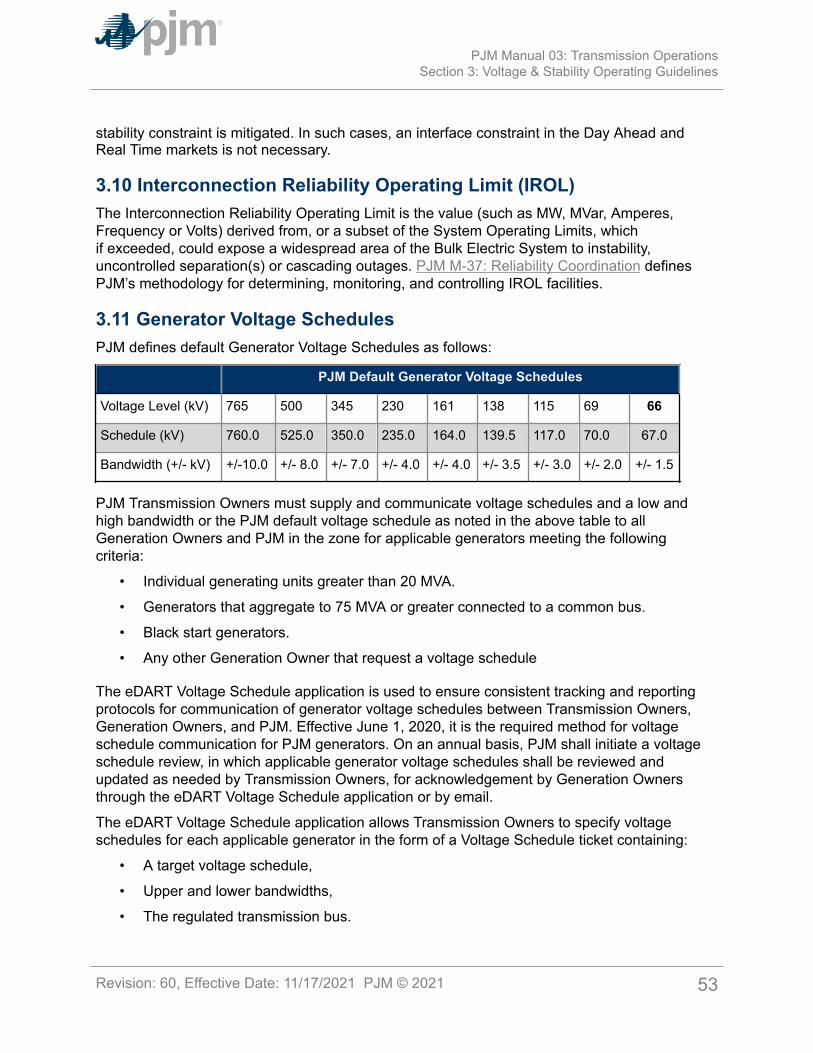
stability constraint is mitigated. In such cases, an interface constraint in the Day Ahead andReal Time markets is not necessary.
3.10 Interconnection Reliability Operating Limit (IROL)The Interconnection Reliability Operating Limit is the value (such as MW, MVar, Amperes,Frequency or Volts) derived from, or a subset of the System Operating Limits, whichif exceeded, could expose a widespread area of the Bulk Electric System to instability,uncontrolled separation(s) or cascading outages. PJM M-37: Reliability Coordination definesPJM’s methodology for determining, monitoring, and controlling IROL facilities.
3.11 Generator Voltage SchedulesPJM defines default Generator Voltage Schedules as follows:
PJM Default Generator Voltage Schedules
Voltage Level (kV) 765 500 345 230 161 138 115 69 66
Schedule (kV) 760.0 525.0 350.0 235.0 164.0 139.5 117.0 70.0 67.0
Bandwidth (+/- kV) +/-10.0 +/- 8.0 +/- 7.0 +/- 4.0 +/- 4.0 +/- 3.5 +/- 3.0 +/- 2.0 +/- 1.5
PJM Transmission Owners must supply and communicate voltage schedules and a low andhigh bandwidth or the PJM default voltage schedule as noted in the above table to allGeneration Owners and PJM in the zone for applicable generators meeting the followingcriteria:
• Individual generating units greater than 20 MVA.
• Generators that aggregate to 75 MVA or greater connected to a common bus.
• Black start generators.
• Any other Generation Owner that request a voltage schedule
The eDART Voltage Schedule application is used to ensure consistent tracking and reportingprotocols for communication of generator voltage schedules between Transmission Owners,Generation Owners, and PJM. Effective June 1, 2020, it is the required method for voltageschedule communication for PJM generators. On an annual basis, PJM shall initiate a voltageschedule review, in which applicable generator voltage schedules shall be reviewed andupdated as needed by Transmission Owners, for acknowledgement by Generation Ownersthrough the eDART Voltage Schedule application or by email.
The eDART Voltage Schedule application allows Transmission Owners to specify voltageschedules for each applicable generator in the form of a Voltage Schedule ticket containing:
• A target voltage schedule,
• Upper and lower bandwidths,
• The regulated transmission bus.
PJM Manual 03: Transmission OperationsSection 3: Voltage & Stability Operating Guidelines
Revision: 60, Effective Date: 11/17/2021 PJM © 2021 53
The specified schedule shall be based on either the PJM default voltage schedule, or theTransmission Owner’s specifications, which may be any one of following schedule types:
• Voltage
• Reactive Power
• Power Factor
The eDART Voltage Schedule application is used to ensure that all applicable generators haveeither a specified voltage schedule or an approved exemption (based on a Transmission Ownerexemption request). Each generator voltage schedule will be submitted by the TransmissionOwner into the application, followed by PJM’s technical review, and then by the GenerationOwner’s acknowledgement.
Generation Owners shall communicate concerns regarding the assignment of the TransmissionOwner voltage schedule/bandwidth or PJM Default Voltage Schedule/Bandwidth to PJM andthe TO for resolution. This communication shall be made via the eDART Voltage Scheduleapplication by using the GO Comment functionality.
A Transmission Owner wishing to exempt an applicable generator from following a voltageschedule shall submit an exemption request via the eDART Voltage Schedule application,including the engineering basis such as, but not limited to, stability limitations, generatorconnected to radial circuits or to a tap changer voltage controlled bus, customer voltage qualitylimitations etc., for such exemption. PJM, in coordination with the affected Transmission Owner,must review the request and provide approval (or denial) based on their analysis, before thechange can go into effect.
PJM Transmission Owners have the authority to direct the Generation Owners to comply withthe voltage schedule in automatic voltage control mode (AVR in service and controlling voltage).Generation Owners are required to maintain the same voltage schedule when AVR is out ofservice unless directed otherwise.
PJM Transmission Owners are required to coordinate voltage schedules, as well as adjustmentsto voltage schedules, with PJM Dispatch and the Generation Owners. PJM Dispatch willapprove/deny adjustments based on PJM EMS Security Analysis results. PJM may electto deviate from voltage schedules based on load levels, transfer patterns, transmission orgeneration outages, or as required to honor pre/post-contingency voltage limits or to maximizetransfer capability based on PJM Security Analysis. The Transmission Owner will providethe Generation Owner with notification requirements for deviations from the specified voltageschedule, and the Transmission Owner will coordinate any deviations with PJM for resolution(see Notes 2 and 3 below).
Transmission Owners will provide the criteria used to develop the voltage schedule orreactive power schedule to the Generation Owner within 30 days of receiving a request. TheTransmission Owner will notify PJM if unable to provide the criteria to the Generation Ownerwithin 30 days of receiving the request.
PJM Transmission Owners have the authority to direct Generation Owners to adjust voltageschedules after coordinating with PJM Dispatch. PJM also has the responsibility and authorityto direct Generation Owner to increase or decrease MVAR output as well as direct theswitching of reactive control devices to maintain voltages as system conditions dictate. PJM
PJM Manual 03: Transmission OperationsSection 3: Voltage & Stability Operating Guidelines
Revision: 60, Effective Date: 11/17/2021 PJM © 2021 54
will communicate these instructions to the Generation Owner through the Transmission Owners.Transmission Owners have the authority to instruct a Generation Owner to increase or decreasevoltage/MVAR output to remain within the Transmission Owner voltage or PJM Default Voltageschedule/bandwidth.
Only PJM has the authority to request a Generation Owner to adjust MVAR output if such adirection adversely impacts the unit’s MW output. In addition, only PJM has the authority toorder a generator on line in the condensing or generating mode to provide voltage support.Also, if a generator is scheduled to come off line either by PJM or the Generation Owner, onlyPJM has the authority to order the generator to remain on line in the condensing or generatingmode to provide voltage/MVAR support.
Generation Owners must coordinate any real-time voltage schedule issues with PJM and theTransmission Owner.
Note:1: PJM monitors system and generator bus voltage via its EMS. In addition, PJM makesavailable to generators via ICCP and/or DNP protocols their designated voltage schedulesand real-time bus voltages to allow the Generation Owners to monitor their unit’s performancerelative to the designated voltage schedule. PJM’s expectation is that the Generation Ownersmaintain their assigned voltage schedule within the prescribed bandwidth and notify PJM andthe TO when a generator is outside of its bandwidth continuously for 30 minutes unlessotherwise specified by the Transmission Owner or exempted in Note 3. When the generatoris again able to maintain its voltage schedule continuously for 30 minutes, notification to PJMand the TO that the generator is back on its voltage schedule is also required.
2: If a generator is unable to maintain its voltage schedule within defined bandwidthscontinuously for 30 minutes, and there is additional calculated leading or lagging MVARreserves based on submitted Facility Reactive Capability Curves (D-Curves), the GenerationOwner is required to notify PJM and the TO within 30 minutes and provide updated FacilityReactive Capability Curves (D-Curves) via eDART by the end of the next business day.
3: If a generator is unable to maintain voltage schedules within bandwidth continuously for 30minutes, and it is operating at full lead MVARs in an attempt to stay within its voltage schedulemaximum limit or at full lag MVARs in an attempt to stay within its voltage schedule minimumlimit, based on submitted Facility Reactive Capability Curves (D-Curves), notifications to PJMand the TO are not required.
4: PJM requires PJM Transmission Owners to notify Generation Owners of applicablegenerators (that meet the criteria documented in 3.11 above) within their transmission zone ofTransmission Owner voltage schedules or PJM default schedules. This notification shall includegenerators connected to systems owned by entities that are not PJM Transmission Ownerssuch as municipalities or electric cooperatives. If the TO is not able to provide a TO voltageschedule to generators (municipalities, electric cooperatives etc.), the TO must notify PJM;and PJM will communicate the PJM default voltage schedule to the Generation Owner via theeDART Voltage Schedule application.
PJM Manual 03: Transmission OperationsSection 3: Voltage & Stability Operating Guidelines
Revision: 60, Effective Date: 11/17/2021 PJM © 2021 55
3.12 Reactive Reserve Check (RRC)PJM leverages a process known as a Reactive Reserve Check (RRC) to assess the RTO’sand its member’s position with respective to dynamic and static reactive (var) power. Typically,an RRC is performed prior to Peak conditions, such as when a Heavy Load Voltage ScheduleWarning (See M-13, PJM Emergency Procedures Manual) has been issued. An RRC may alsobe needed during light load conditions, such as a Minimum Generation Alert (See M-13, PJMEmergency Procedures Manual) issuance. In addition, PJM may issue an RRC once a week,such as a Sunday check, for testing purposes. For PJM, reactive power is expressed in MVAR,and for the purposes of an RRC, that MVAR reserve is expressed:
• as MVAR available (lagging) to the system for a Peak (heavy-load) RRC;
• as MVAR available (leading) to be taken off the system for a Valley (light-load) RRC.
Reactive assets for the PJM RTO area consist of PJM modeled generating units, synchronouscondensers, static var compensators (SVCs), capacitors, and reactors.
PJM assesses the reactive reserve of the associated equipment via three (3) key metrics:
1. Capability: The lagging (and/or leading) capability for a given piece of reactiveequipment.
a. For generating units, synchronous condensers and SVCs, the capability is comprisedof the permissible range of operation for the equipment, also known as the ReactivePower Capability Curve. For an RRC, PJM utilizes the lagging/leading MVAR pointsof the curve corresponding to the real-time real power (MW) output of the facility.Thus, capability is expressed as a maximum (lagging) and minimum (leading) MVARrange.
i Reduced/expanded capability should be communicated through an eDART ticketand communicated to PJM Dispatch.
b. For capacitors and reactors, the capability is single MVAR value corresponding to themaximum (lagging) MVAR capability for capacitors, or a minimum (leading) MVARcapability for reactors, PJM would anticipate at unity power factor.
2. Status: Status reflects the real-time connectivity to the PJM system, and is expressed asOnline or Offline. Equipment real-time status is to be provided to (typically derived fromcircuit breaker status and/or MW/MVAR output) PJM via telemetry. Real-time status ofan Automatic Voltage Regulator (AVR) for a given generator or synchronous condenser,or the automatic/manual response for a given SVC, must also be communicated to PJMDispatch. Unless otherwise agreed to or communicated to PJM Dispatch:
a. When a generator is above economic minimum real power output, PJM considersthe AVR to be in-service/automatic mode and regulating voltage.
b. When a synchronous condenser is online and connected to the grid, PJM considersthe AVR to be in-service/automatic mode and regulating voltage.
c. When an SVC is connected to the grid, PJM considers the SVC to be in automaticmode and regulating voltage.
PJM Manual 03: Transmission OperationsSection 3: Voltage & Stability Operating Guidelines
Revision: 60, Effective Date: 11/17/2021 PJM © 2021 56

3. Availability: The availability and/or unavailability of a reactive device in full iscommunicated to PJM through the absence of a PJM eDART ticket (availability) or thepresence of an eDART ticket (unavailability) which identifies the equipment as beingunavailable.
Note:For the purposes of this manual and the RRC, in order to ensure the accuracy of PJM’sRC/TOP tools, PJM Members shall provide timely updates to PJM Dispatch through appropriatetools regarding any impact to the Capability, Status, and/or Availability of their reactiveequipment. This can be done via telemetry, through maintaining timely and appropriate updateswith respect to eDART tickets, and/or direct communication to PJM Dispatch as the situationwarrants.
PJM Actions:• PJM dispatcher initiates the RRC within the eDART application and requests response
for the entire PJM RTO or on a Control Zone basis, as necessary. (Default is entire PJMRTO).
• PJM dispatcher announces the RRC to members via PJM All-Call (or backupcommunications channels if PJM All-Call is not available).
• PJM dispatcher takes a snapshot of reactive reserves from the PJM EMS system forcomparison purposes.
• PJM dispatcher works with member to resolve/rationalize reported differences in reactivereserves, correcting capability data as needed to ensure accurate Contingency Analysisresults.
Generation Owner Actions:• Outside of an RRC:
o Report Capability, Status and/or Availability of their reactive equipment per normalprocedures/tools.
o Notify TO/PJM regarding unit reactive performance issues, and update eDART asappropriate.
• During an RRC:o No action required, unless support directly requested by PJM/TO dispatcher.
Transmission Owner Actions:• Outside of an RRC:
o Report Capability, Status and/or Availability of their dynamic/static reactiveequipment per normal procedures/tools.
o Review eDART Reactive Capability Curves for units within the TO’s zone, andupdate LCC EMS or reconcile deviations with PJM/GO as needed.
PJM Manual 03: Transmission OperationsSection 3: Voltage & Stability Operating Guidelines
Revision: 60, Effective Date: 11/17/2021 PJM © 2021 57
o Compare LCC EMS information on an equipment level basis to PJM EMS data viathe New Reactive Reserve Check: RRC Self-Check form.
• During an RRC:o TO enters required data in eDART via the eDART RRC Web form or via XML upload.
Note:TO members seeking to provide ICCP submittal to an RRC, or with questions regarding theRRC process, should reach out to [email protected] information can be found via PJM eDART User Group, the PJM eDART site, the PJMTech Change Forum, and related committee level meetings.
PJM Manual 03: Transmission OperationsSection 3: Voltage & Stability Operating Guidelines
Revision: 60, Effective Date: 11/17/2021 PJM © 2021 58
Section 4: Reportable Transmission Facility OutagesWelcome to the Reportable Transmission Facility Outages section of the PJM Manual forTransmission Operations. In this section, you will find the following information:
• A description of the general principles of scheduling outages (see “General Principles”).
• How the Transmission Owner schedules a transmission facility outage (see “SchedulingTransmission Outage Requests”).
• How PJM processes a Transmission Outage Request (see “Processing TransmissionOutage Requests”).
• A description of the equipment failure procedures (see “Equipment Failure Procedures”).
• A description of the Transmission Acceleration Outage Process.
4.1 General PrinciplesTransmission Owners have the right and obligation to maintain and repair their portion ofthe transmission system. PJM approves all Reportable Transmission Facility outages prior toremoval of the equipment from service. PJM will coordinate scheduled outages of all ReportableTransmission Facilities with planned generation outages that are submitted to PJM and mayaffect PJM RTO operation. For purposes of scheduling, Reportable Transmission Facilitiesinclude, but are not limited to, lines, transformers, phase angle regulators, buses, breakers,disconnects, Bulk Electric System capacitors, reactors, and all related equipment.
Generation Owners that own transmission equipment such as circuit breakers, capacitor banks,etc., do not have the capability to submit outage requests on transmission equipment in eDART.As a result, for Reportable Transmission Facilities in each TO zone, the Generation Ownermust notify the affected Transmission Owner who must then submit outage requests to PJMvia eDART for this generation-owned equipment as soon as practical after they are informedof the outage. It is the responsibility of the Generation Owner to keep the Transmission Ownerupdated on the status of this equipment and any associated outage requests.
PJM maintains a list of Reportable Transmission Facilities. Each Transmission Owner submitsthe tentative dates of all transmission outages of Reportable Transmission Facilities to PJM asfar in advance as possible.
Procedures and timelines are established for the scheduling, coordinating, requesting, studying,approving, and notifying of the transmission outage to/by the appropriate Transmission Ownerand PJM. The procedures and timelines are identified in this section and are periodicallyreviewed and revised.
Under certain conditions such as extreme weather, peak load, heightened homeland security,etc., PJM will evaluate the need to operate the Power Grid in a more conservative manner.Actions that may be taken in these special circumstances include, but are not limited to,canceling by Transmission Owner, denying by PJM, or rescheduling outages and returningoutaged equipment to service. The status of rescheduled outages is described in detail underthe subheading, “Rescheduling Outages”.
PJM Manual 03: Transmission OperationsSection 4: Reportable Transmission Facility Outages
Revision: 60, Effective Date: 11/17/2021 PJM © 2021 59
4.2 Scheduling Transmission Outage RequestsEach Transmission Owner shall submit the tentative dates of all planned transmission outagesof Reportable Transmission Facilities to PJM via eDART as far in advance as possible andupdate PJM at least monthly. For transmission outages exceeding five days, the TO shall usereasonable efforts to submit the planned outage schedule via eDART one year in advance butno later than 0000 hours on the first of the month six months in advance of the requested startdate along with a minimum of monthly updates.
PJM maintains a planned transmission outage schedule for a period of at least the next13 months. The planned transmission outage schedule is posted, subject to change, on thePJM Open Access Same-time Information System (OASIS). Planned transmission outagesare given priority based on the date of submission. All planned transmission outages will beposted on OASIS within 20 minutes of Transmission Owner submittal of the outage throughthe PJM eDART system, with further updates as new information is provided in eDART. PJMperiodically reviews all submissions of planned transmission outages and considers the effect ofproposed transmission outages upon the integrated operation of the transmission system usingestablished operating reliability criteria, as described within Sections 2 and 3 of this manual.Advance notification assures that the outage is reflected in both the ATC analysis and the FTRAuction.
4.2.1 Outage Submittal Rules• The TO is required to submit all outage requests in excess of 5 calendar days in duration
before the 1st of the month six months in advance of the start of the outage.• Outages exceeding 30 calendar days in duration for the following planning cycle (June
1 – May 31) must be submitted before February 1, preceding the planning year (i.e., forplanning year “June 1, 2020 – May 31, 2021”, outages would need to be submitted priorto February 1st, 2020).
The most restrictive deadline will be enforced. In other words, an outage exceeding 30 days induration starting in June would have to be submitted no later than November 30th at 2359 hoursto be considered on-time.
• The TO is required to submit all outage requests less than or equal to 5 calendar days induration before the 1st of the month prior to the month of the requested start date of theoutage.
Recognizing that this may not always be possible, the following table illustrates the differenttime frames in which an Outage Request can be submitted and the different Actions PJM cantake. The “PJM Actions” are defined in more detail in the Section: “Processing TransmissionOutage Requests, PJM Actions”.
Request Submitted Ticket ReceivedStatus
PJM Actions
Outage > 30 Calendar Days
PJM Manual 03: Transmission OperationsSection 4: Reportable Transmission Facility Outages
Revision: 60, Effective Date: 11/17/2021 PJM © 2021 60
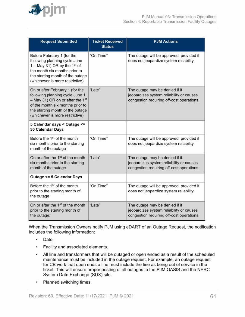
Request Submitted Ticket ReceivedStatus
PJM Actions
Before February 1 (for thefollowing planning cycle June1 – May 31) OR by the 1st ofthe month six months prior tothe starting month of the outage(whichever is more restrictive)
“On Time” The outage will be approved, provided itdoes not jeopardize system reliability.
On or after February 1 (for thefollowing planning cycle June 1– May 31) OR on or after the 1st
of the month six months prior tothe starting month of the outage(whichever is more restrictive)
“Late” The outage may be denied if itjeopardizes system reliability or causescongestion requiring off-cost operations.
5 Calendar days < Outage <=30 Calendar Days
Before the 1st of the monthsix months prior to the startingmonth of the outage
“On Time” The outage will be approved, provided itdoes not jeopardize system reliability.
On or after the 1st of the monthsix months prior to the startingmonth of the outage
“Late” The outage may be denied if itjeopardizes system reliability or causescongestion requiring off-cost operations.
Outage <= 5 Calendar Days
Before the 1st of the monthprior to the starting month ofthe outage
“On Time” The outage will be approved, provided itdoes not jeopardize system reliability.
On or after the 1st of the monthprior to the starting month ofthe outage.
“Late” The outage may be denied if itjeopardizes system reliability or causescongestion requiring off-cost operations.
When the Transmission Owners notify PJM using eDART of an Outage Request, the notificationincludes the following information:
• Date.• Facility and associated elements.• All line and transformers that will be outaged or open ended as a result of the scheduled
maintenance must be included in the outage request. For example, an outage requestfor CB work that open ends a line must include the line as being out of service in theticket. This will ensure proper posting of all outages to the PJM OASIS and the NERCSystem Date Exchange (SDX) site.
• Planned switching times.
PJM Manual 03: Transmission OperationsSection 4: Reportable Transmission Facility Outages
Revision: 60, Effective Date: 11/17/2021 PJM © 2021 61
• Job description.• Availability/emergency return time.
Note:Outages can be classified by PJM as Market Sensitive if necessary. This option is used inspecific instances. Market Sensitive is any equipment or facility that reveals the future status ofa generating unit. Generally, these outages are not posted on the PJM OASIS.
4.2.2 Hotline / In Service Work Requests / Protective Relay Outages / FailuresTo properly coordinate the operation of the Bulk Electric System, Transmission Owners mustnotify PJM of hot-line work and protective relay outages. Several days’ notice is requested toenhance coordination. For hotline work impacting the protection system zone of clearance orincreasing the clearing time, a ticket must be submitted at least by 8am three days prior to thestart date in order to be considered “on-time”. The notification includes the following information:
• An outage or degradation of either the primary or back-up relay protection associatedwith any EHV (345 kV and above) facility.
Note:PJM will model any delayed clearing as a result of relay outages or degradation in the TSA toolfor stability.
• An outage of any other major relay protection scheme significant to EHV operation.• An outage of an automatic recloser protection associated with an EHV circuit or any
hotline work (reclosers in or out) on EHV facilities. PJM dispatcher is informed prior toauto-reclosers being taken out of service. All planned outages shall be submitted viaeDART. All unplanned outages shall be communicated to PJM Dispatch and submittedvia eDART.
Note:An eDART ticket is not required for RTU/Datalink outages. Refer to Manual 1 Section 3.2.4 forcommunication requirements for Unplanned RTU outages and Section 3.8.1 for communicationrequirements for Planned RTU outages.
Note:Under normal system conditions, Transmission Owners may elect not to restore “automaticreclosing” during multiple-day daily EHV equipment Hotline work. However, “automaticreclosing” must be restored from June 1st – August 31st (peak loads). In addition, PJM mayrequest the TO to restore automatic reclosing during other projected peak load conditions,during thunderstorms or inclement weather, or during other unusual conditions which couldadversely impact system reliability.
• In the case of Bulk Electric System facilities with no back-up relay protection, theTransmission Owner or Generation Owner should remove the facility from service beforeremoving the primary relay protection when possible. If the facility cannot be removedfrom service, the Transmission Owner or Generation Owner shall notify PJM Dispatch
PJM Manual 03: Transmission OperationsSection 4: Reportable Transmission Facility Outages
Revision: 60, Effective Date: 11/17/2021 PJM © 2021 62
verbally and through eDART of the impacted facility(s) and the remote fault clearingpoints. PJM Dispatch will modify the EMS Network Contingency analysis to reflect theremote clearing.
• In the case of any EHV automatic recloser outages, some limitations may need to beplaced on the number of reclosers that may be outaged concurrently. Under normalconditions, PJM does not restrict the number of automatic reclosers that are out-of-service. However, under certain operating conditions, the number of automatic reclosersout-of-service in that electrical area may need to be limited if an analysis indicatespotential reliability concerns. For example, if an EHV line is out-of-service, this will holdtrue. In this case, the requesting Transmission Owners are informed of the situation andasked to reschedule the work.
• Instances when relay testing or construction personnel are working in EHV substations,other than those in conjunction with scheduled facility outages previously approved byPJM, which may jeopardize the reliable operation of the substation.
• Transmission and Generation Owners shall notify PJM Dispatch of any protectionsystem failures (as soon as possible) or unavailability (as scheduled) that impact thecapability of protection relay systems on any facility on the list of Reportable facilitiesif such unavailability may result in a change in remote clearing, requiring PJM tomodify PJM EMS Network Application Contingencies or switching the impacted facilityout-of-service. PJM Dispatch shall notify affected Transmission Owners, TransmissionOperators and Reliability Coordinators to ensure contingencies are modeled properly inSecurity Analysis and/or transient analysis. PJM Dispatch shall log such contingencymodifications in the PJM logging system.
Note:PJM relies on Transmission and Generation Owners to identify, assess, and notify PJM ofchanges, degradations, or outages to relay systems that impact normal fault clearing.
Note:Facilities with degraded or no relay protection will be switched out-of-service; unless by doingso would create a load shed situation. In this case, PJM would model the remote clearingpoints and operate to control any resulting contingencies using normal operating proceduresincluding PCLLRWs. These actions should be completed within 30 minutes of identification ofthe protection problem.
4.2.3 Energizing New FacilitiesIn order for PJM to properly model changes in system configuration, as much advancednotification as possible is required when a new facility, a reconfigured facility, is scheduledto be energized. This also includes a re-conductoring or equipment replacement that changesthe impedance or rating of a facility. Transmission Owners must notify PJM of such changes bychecking the Cut-In flag in the eDART outage ticket. This information should be submitted toPJM as far in advance as possible to ensure inclusion in the quarterly EMS model update but atminimum shall be consistent with the outage submittal rules. If energizing a new facility involvesmultiple outages in different periods, the Cut-In flag shall only be checked for the outage thatupon completion will result in the energized facility.
PJM Manual 03: Transmission OperationsSection 4: Reportable Transmission Facility Outages
Revision: 60, Effective Date: 11/17/2021 PJM © 2021 63
4.2.4 Protection System CoordinationEach Generation Owner shall coordinate any new protection system or protectionsystem change with their local Transmission Owner and PJM (email [email protected]). PJM will collect the information on these changes from theGeneration Owner and post on the secure PJM Relay Subcommittee SharePoint site.
Note:PJM relies on Transmission and Generation Owners to notify PJM of changes or degradationsto relay systems that changes normal fault clearing. PJM models such change within the PJMEMS system by modifying PJM Security Analysis Contingencies.
4.2.5 Generator Voltage Regulator ChangesAn outage of any unit generator voltage regulator, supplementary excitation control, or powersystem stabilizers must be communicated to PJM though eDART as far in advance as possible.The Generator Owner must submit these outages. (Refer to the PJM M-14D: GeneratorOperational Requirements.)
4.2.6 Peak Period Outage Scheduling GuidelinesTransmission Owners should avoid scheduling any outage in excess of 5 days in duration witha restoration time greater than 72 hours that may result in increased risk to system reliabilityduring peak summer and winter periods. These periods are defined as June 15 – September 15and January 1 – February 28, respectively.Due to the risk of having other unexpected forced outages during the peak periods, the outagesresulting in the following conditions with a restoration time greater than 72 hours will be denied:
• Actual or post-contingency thermal or voltage issues with insufficient generation forcontrol.
• Constraints that are load sensitive with limited controlling actions.• Stability issues.• Bottled generation.• Localized congestion requiring significant generation reduction to control.• Non-localized congestion requiring wide-spread generation reduction to control.
Transmission Owners shall screen for such outages prior to submittal in eDART and look toreschedule these outages during non-peak periods. PJM may grant exception to ensure RTEPupgrades are installed within specified timeframes or as special circumstances warrant.
4.2.7 Outage Scheduling Exceptions• PJM reserves the right to approve, deny, or reschedule any outage deemed necessary
to ensure system reliability on a case by case basis regardless of date of submission.• Outages not submitted on-time but scheduled in conjunction with existing outages will be
reviewed and approved by PJM on a case-by-case basis in order to take advantage ofexpected system conditions.
PJM Manual 03: Transmission OperationsSection 4: Reportable Transmission Facility Outages
Revision: 60, Effective Date: 11/17/2021 PJM © 2021 64
• A “Late” outage (see Table in Section 4.2.1), regardless of duration, not expected toimpact the transmission system reliability or result in system congestion at any pointwithin the scheduled duration, may be approved.
4.2.8 Emergency and Forced OutagesPJM recognizes that Emergency Outages must be taken. If it is determined that the outagemay create an unreliable operating condition the outage will not be approved, but it will berecognized by PJM that the outage will occur.Transmission Owners report forced transmission outages of Transmission Facilities to PJM, todirectly connected Balancing Authorities and to any Other PJM member that may be affectedas soon as the forced transmission outage occurs or as soon as it is anticipated that forcedoutage will occur. The Transmission Owner also submits an eDART ticket for the outage withall pertinent information that is available at that time and updates the ticket as new informationbecomes available.For emergency outages that require the scheduling of manpower, ordering of parts, etc. andtherefore cannot come out of service immediately the TO shall submit a ticket in eDART for thefuture date in which the outage is expected to come out of service, set the Emergency flag, andwrite a description in the eDART ticket explaining the emergency condition and why the outagecannot come out of service immediately.
4.2.9 Rescheduling OutagesA planned transmission outage that is rescheduled or cancelled because of inclement weatheror at the direction or request of PJM retains its “On-Time” status (if applicable) and priority as aplanned transmission outage with the PJM approved rescheduled date.If an outage request is rescheduled or cancelled for reasons other than inclement weather andnot at the direction of PJM, the rescheduled or cancelled and resubmitted outage is treated asan unplanned outage request.
Note:Transmission Owners should use reasonable efforts to assess all outages for the next two daysand submit changes to outage tickets due to last minute cancellation, revision to scheduledreturn time of active outage, or other modification to PJM whenever possible by 06:00 a.m. butby no later than 09:30 a.m. for input into the day-ahead market model.
The revised outage request may lose its priority as an “On-Time” outage as indicated by thefollowing below.Revisions to “On-Time” scheduled outages lasting 5 Days or less:
• If the revised outage request will occur entirely during the originally scheduled month(s),it will retain its “On-Time” status if applicable.
• If the revised outage request will occur during a different month(s), the revision must besubmitted by the first of the month prior to the revised month(s) in which the outage willtake place to be considered “On-Time”.
• If the revised outage request results in the ticket duration being greater than 5 days, theticket’s “On-Time” status will be re-evaluated as if submitted for the first time.
• If any piece of equipment is added to the ticket’s outaged equipment list by the TO.
PJM Manual 03: Transmission OperationsSection 4: Reportable Transmission Facility Outages
Revision: 60, Effective Date: 11/17/2021 PJM © 2021 65
Revisions to “On-Time” scheduled outages exceeding 5 Days in duration:• If the revised outage request will occur entirely during the originally scheduled month(s),
it will retain its “On-Time” status if applicable.• If the outage request moves to a new month which is further out into the future, the
revision must be submitted by the first of the month prior to the revised month in whichthe outage will take place to be considered “On-Time”.
• If the outage request moves to a new month which is nearer to the current date, therevision must be submitted by the first of the month six (6) months prior to the revisedmonth in which the outage will take place to be considered “On-Time”.
• If the scheduled outage is more than 30 days and the revised outage request resultsin the ticket crossing into a different Planning Year, the ticket’s “On-Time” status will bere-evaluated as if submitted for the first time.
• If the revised outage request results in the ticket duration being greater than 30 days, theticket’s “On-Time” status will be re-evaluated as if submitted for the first time.
• If any piece of equipment is added to the ticket’s outaged equipment list by the TO.
Revisions to “Late” scheduled outages will be re-evaluated by PJM as “On-Time” or “Late” asdictated by the rules in the Section entitled “Outage Submittal Rules” (Section 4.2.1).PJM coordinates outage rescheduling with the PJM Transmission Owners to minimize impactson system operations.4.2.9.1 Direct Billing for Late OutagesIn order to avoid cancellation or rescheduling of a late outage, a Transmission Owner may electto pay for off-cost operations associated with the outage consistent with OATT Attachment Kand OA Schedule 1 in cases where PJM can specifically identify and assign the costs to theT.O. and after review and approval of such request by PJM.PJM may assign to the Transmission Owner, at their consent, the generation off-cost orreductions in demand associated with their late outage submittal related to RTEP upgradesprovided that delay of such outage would result in failure to meet the reliability based in-servicedate. Should the T.O. elect not to pay for the off-cost operations, the emergency RTEP outagewill be posted as a special notice on the PJM OASIS.In order to minimize market impact, direct billing costs outlined in this section apply only to thoseoutages where controlling generation or reductions in demand can be identified in advance yetare not included in the LMP calculation. Outages resulting in overloads where the generatorcosts cannot be isolated thereby resulting in congestion do not fall under this proposal. ATransmission Owner would not be directly assigned costs associated with late outages dueto unforeseen circumstances such as but not limited to inclement weather, existing outageextensions, permitting or zoning issues, equipment delivery delays, generation, or reductions indemand availability.
4.2.10 Coordinating Outage Requests with Other TOsIn the event that a contemplated scheduled outage of one Transmission Owner’s facilityaffects the availability of another Transmission Owner’s facility, it is the responsibility ofthe Transmission Owner initiating the request to notify the affected TO or other BalancingAuthorities for their consideration before submitting the request to PJM. If agreeable to all
PJM Manual 03: Transmission OperationsSection 4: Reportable Transmission Facility Outages
Revision: 60, Effective Date: 11/17/2021 PJM © 2021 66
Transmission Owners or Balancing Authorities, the initiating Transmission Owner submits anoutage request to PJM all other PJM Members that may be affected are notified.
4.2.11 Coordinating Outage Requests with other RTOsIn the event of a contemplated scheduled outage of a tie between the PJM RTO andneighboring entity, the Transmission Owner initiating the request discusses the outage withthe directly connected Balancing Authority and/or Transmission Operator for their consideration.Likewise, if it is expected that such an outage will be extended beyond its scheduled time,this is discussed with the directly connected Balancing Authority and/or Transmission Operator.If agreeable to the directly connected Balancing Authority and/or Transmission Operator, theinitiating Transmission Owner submits an outage request to PJM, all other systems that maybe affected are notified. This procedure also applies to a tie between the PJM RTO and anadjacent Balancing Authority and/or Transmission Operator whenever the PJM RTO initiates anoutage request. Adjacent Balancing Authorities and/or Transmission Operators are expected tofollow a similar procedure.
4.2.12 Coordinating Outage Requests with Planned Nuclear Generation OutagesWhen a Transmission Owner submits an Outage Request that will open a Nuclear GeneratingStation’s Unit Breaker the following guidelines shall be observed:
• All Nuclear Unit breaker Outage Requests shall be coordinated closely with the NuclearStation to coincide with a Unit outage.
• In the case that the Outage Request cannot be delayed until the next Unit Outage, theNuclear station should be given at least six weeks’ notice. The schedule for opening theUnit Breaker must be closely coordinated with the station. The length of time that thebreaker remains open should be minimized.
PJM will work with the Nuclear Station’s and the Transmission Owner’s outage needs.The Nuclear Generating Stations coordinate the scheduling of a Unit Breaker outage andinternal plant equipment outages and testing to minimize station risk. Adherence to outageschedule and duration is critical to the plant during these evolutions. Emergent plant ortransmission system conditions may require schedule adjustments, which should be minimized.Any change to the outage schedule that impacts the Unit Breakers shall be communicated tothe nuclear generator operator.
4.2.13 Coordinating Outage Requests with Impacted GeneratorsTransmission Owners will adhere to all PJM requirements regarding Transmission OutageRequests previously detailed in this section.Transmission Owners will determine if their transmission outage impacts area generation. If thetransmission outage forces an area generator off line, the Transmission Owner will notify theimpacted generator.PJM and Transmission Owners coordinate transmission outages with planned outages forgenerators submitted to PJM. In the maintenance planning process, if submitted in a timelymanner, planned generator outage requests are given priority over planned transmission outagerequests, and hence Transmission Owners should make an effort in aligning transmissionoutage work with the planned outage for generation.
PJM Manual 03: Transmission OperationsSection 4: Reportable Transmission Facility Outages
Revision: 60, Effective Date: 11/17/2021 PJM © 2021 67
In accordance with PJM Open Access Transmission Tariff, Attachment K – Appendix, section1.9.2, if a Transmission Owner is planning to submit an outage that will make a generator facilityunavailable, such outage shall be coordinated with the affected Generation Owner or the plantoperator.In addition to adhering to the on-time outage submittal rules, the Transmission Owner mustinform the affected Generation Owner or the plant operator of such outage, as early as practical,but no later than six weeks prior to start of the transmission outage and should document on thetransmission outage ticket the date of notification and the person / group that was notified. TheTransmission Owner must communicate the subsequent changes to the transmission outageschedule to the Generation Owner or the plant operator. Failure to provide notification tothe Generation Owner or the plant operator could result in denial of the transmission outagerequest.PJM resolves potential outage conflicts based on system reliability. PJM performs the followingactivities:
• Reviews the transmission and generator maintenance schedules to coordinate majortransmission and generator outages and communicates with submitting PJM Membersto assist in attempting to minimize anticipated constrained operations.
• Recommends adjustments to transmission outage schedules throughout the year tocoincide with planned generator outages within the PJM RTO and surrounding BalancingAuthorities.
• Communicates with submitting PJM Members to assist in attempting to minimize theforecast PJM RTO production cost based on anticipated market-based prices.
4.3 Processing Transmission Outage RequestsTransmission Owners submit Outage Requests in eDART for all outages to PJM in advance ofthe outage start date. The Outage Request shall be submitted as far in advance as possible.PJM considers all transmission outages in the following priority order:
• Forced or emergency transmission outages.
• Transmission outage requests submitted “On Time” (refer to Section 4.2.1 for “On Time”transmission outage submission requirements).
• Transmission outage requests submitted “Late” (refer to Section 4.2.1 for transmissionoutage submission requirements).
Exhibit 5 presents how PJM processes Transmission Outage Requests.
PJM Manual 03: Transmission OperationsSection 4: Reportable Transmission Facility Outages
Revision: 60, Effective Date: 11/17/2021 PJM © 2021 68
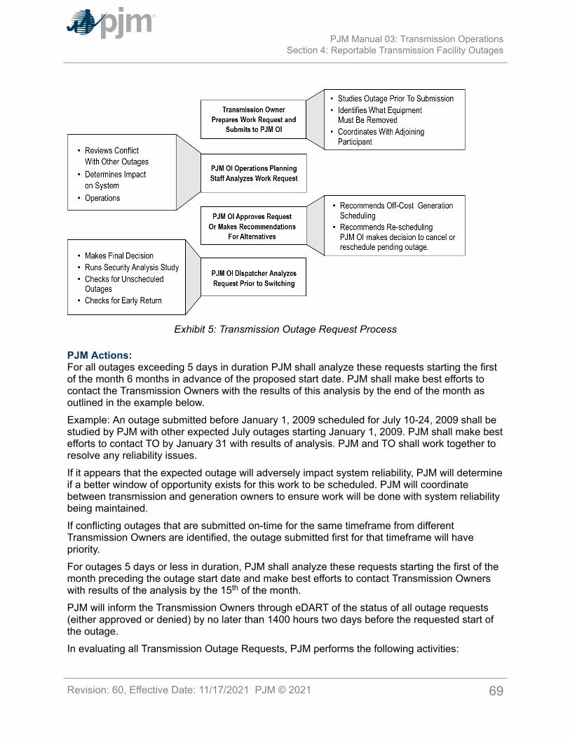
Exhibit 5: Transmission Outage Request Process
PJM Actions:For all outages exceeding 5 days in duration PJM shall analyze these requests starting the firstof the month 6 months in advance of the proposed start date. PJM shall make best efforts tocontact the Transmission Owners with the results of this analysis by the end of the month asoutlined in the example below.Example: An outage submitted before January 1, 2009 scheduled for July 10-24, 2009 shall bestudied by PJM with other expected July outages starting January 1, 2009. PJM shall make bestefforts to contact TO by January 31 with results of analysis. PJM and TO shall work together toresolve any reliability issues.If it appears that the expected outage will adversely impact system reliability, PJM will determineif a better window of opportunity exists for this work to be scheduled. PJM will coordinatebetween transmission and generation owners to ensure work will be done with system reliabilitybeing maintained.If conflicting outages that are submitted on-time for the same timeframe from differentTransmission Owners are identified, the outage submitted first for that timeframe will havepriority.For outages 5 days or less in duration, PJM shall analyze these requests starting the first of themonth preceding the outage start date and make best efforts to contact Transmission Ownerswith results of the analysis by the 15th of the month.PJM will inform the Transmission Owners through eDART of the status of all outage requests(either approved or denied) by no later than 1400 hours two days before the requested start ofthe outage.In evaluating all Transmission Outage Requests, PJM performs the following activities:
PJM Manual 03: Transmission OperationsSection 4: Reportable Transmission Facility Outages
Revision: 60, Effective Date: 11/17/2021 PJM © 2021 69
• Studies and approves any emergency outages that do not result in EmergencyProcedures. If an emergency outage is expected to result in Emergency Procedures,it will be discussed with the TO to determine the impact and risks associated with takingthe outage at that time.
• Studies and approves Transmission Outage Requests that are submitted “On Time” anddo not jeopardize the reliability of the PJM System.
• Studies and approves Transmission Outage Requests that are submitted “Late” and donot cause congestion on the PJM System. Determines if a “Late” Request may causecongestion and advises the Transmission Owner of any solutions available to eliminatethe congestion. If a generator Planned or Maintenance Outage request is contributingto the congestion, PJM can request the Generation Owner to defer the outage. If nosolutions are available, PJM may require the Transmission Owner to reschedule theoutage.
• During anticipated emergency conditions, orders all work on Reportable TransmissionFacilities that can be returned to service interrupted and the facilities returned to serviceuntil the emergency condition is relieved, if possible.
PJM, as system conditions warrant, identifies opportunities for, and encourages, coordinationof all generator and transmission maintenance outages. When actual or anticipated systemconditions change such that, at the discretion of PJM, the rescheduling of a transmission outageis advisable, PJM informs the Transmission Owner of the conditions and available alternatives.The Transmission Owner involved considers the impacts of proceeding with the outage asadvised by PJM and may either proceed knowing the estimated impacts on the remainingfacilities or postpone the outage. If the outage is not postponed, PJM determines and recordsthe appropriate impacts or changes to system limits and takes the steps required to maintainestablished operating reliability criteria as mentioned within Section 1 of this manual.PJM evaluates planned outages of Reportable Transmission Facilities to determine whether anoutage may cause the simultaneous loss of multiple facilities. When non-reportable equipmentoutages at a station occur, which can lead to the simultaneous loss of more than one reportabletransmission or generator facility for any single facility malfunction or failure, PJM must beinformed. The Transmission Owners are responsible to report such conditions to PJM as soonas they are recognized.
4.3.1 Notification of Transmission OutagesThe Transmission Owners are responsible for reporting outages on facilities contained withinthe Transmission Facilities List Database (available on the PJM website – www.pjm.com).The eDART reporting system is used to inform PJM and others of the outage according topredefined indexing keys.Transmission Owners must notify PJM of the unavailability of other transmission componentsthat affect the capability of protection of facilities on the list of Reportable TransmissionFacilities. Such unavailability may result in a degradation of protection systems which couldresult in remote clearing of a transmission faults requiring PJM to modify PJM EMS NetworkApplication Contingencies or switching the impacted facility out-of-service.Transmission Owners report forced transmission outages of Transmission Facilities to PJM, todirectly connected Balancing Authorities that may be affected, and to a jointly-operating PJM
PJM Manual 03: Transmission OperationsSection 4: Reportable Transmission Facility Outages
Revision: 60, Effective Date: 11/17/2021 PJM © 2021 70
Member as soon as the forced transmission outage occurs or as soon as it is anticipated thatforced outage occurs or is imminent.Transmission Owners must report outages that under expected system conditions may affectsystem reliability even though these facilities may not be listed as a Reportable TransmissionFacility. This includes outages that may result in multiple facility trippings.PJM dispatcher then informs all other systems that may be affected. PJM dispatcher logs alloutages and, as required, reports to and makes necessary arrangements with the appropriatepersonnel from neighboring RTOs, ISOs, and Balancing Authorities.
4.3.2 Real-Time Switching Notification ProceduresTransmission Owners must request final approval from PJM Transmission Dispatcher one-halfhour prior to the expected switching time of any reportable facility. If the switching for thework on the associated outage request has not been completed within 30 minutes from PJMdispatcher’s approval, the Transmission Owner must notify the PJM dispatcher of the delay.If the Transmission Owner dispatcher expects the switching to exceed 30 minutes, the TOdispatcher can notify the PJM operator during the initial phone call. No additional notification willbe required unless PJM specifically requests to be notified immediately prior to switching.
• PJM considers equipment switched out of service once it has been taken out of networkoperation, predominately via breakers.
• PJM considers equipment restored when it has been returned to network operation.• PJM considers relaying disabled/enabled when they’ve been placed in their intended
status.
If for any reason, PJM dispatch approves switching for planned maintenance, and actual orcontingency violations are observed, PJM dispatch will direct the facility to be returned toservice until system conditions can be adjusted and the outage permitted to continue withoutviolating operating criteria.When a reportable facility is to be returned to service, the responsible Transmission Ownerreports to the PJM Transmission Dispatcher for approval prior to returning the outaged facility toservice. This is done so that any generation changes or transmission adjustments can be madeto assure reliable operation of the system.
Note:In general, each neighboring RC, TOP, BA, TO, GO, TSP, and LSE shall use line/equipmentterminals and voltage when referring to transmission facilities of an interconnected network,utilizing uniform identifiers as needed to clarify identification and ensure accurate real-timecommunications.
4.4 Equipment Failure ProceduresTransmission Owners must promptly notify PJM dispatch of any equipment failures involvingBES facilities. Transmission Owners promptly conduct investigations of equipment malfunctionsand failures and forced transmission outages in a manner consistent with good utility practiceand NERC, RFC, and SERC Standards. Causes of failures shall be communicated to PJMdispatch as they are determined. In order to permit other Transmission Owners to take
PJM Manual 03: Transmission OperationsSection 4: Reportable Transmission Facility Outages
Revision: 60, Effective Date: 11/17/2021 PJM © 2021 71
advantage of information leading to possible trends in equipment failures, the TransmissionOwners supply the results of such investigation to PJM, other Transmission Owners, and theappropriate entities in NERC, RFC and SERC. Transmission Owners establish guidelines forthe level of resources to be applied to restore equipment to service following a failure. TheTransmission Owners obtain from PJM the information and support services needed to complywith their obligations.
4.5 Transmission Outage Acceleration ProcessWelcome to the Transmission Outage Acceleration Process section of the PJM Manual forTransmission Operations. In this section, you will find the following information:
• A description of the general principles of requesting Transmission Facility OutageAcceleration (see “General Principles”).
• A timeline of the process.
• How PJM processes a Transmission Outage Acceleration Request (see “ProcessingTransmission Outage Acceleration Requests”).
4.5.1 General PrinciplesTransmission Owners provide notice of planned outages to PJM in accordance with therequirements in the Open Access Transmission Tariff and applicable Transmission OwnersAgreement as detailed in this Manual (refer to Section 4.2.1 for “On time” transmission outagesubmission requirements).Under certain circumstances, it may be beneficial to investigate the possibility of moving oraccelerating a transmission facility outage if shortening the overall outage time or moving thestart/stop dates can alleviate transmission congestion or revenue inadequacy. To accommodateoutages that may be accelerated under this process, PJM will review ”on time” outagesexceeding 5 days in duration submitted by the Transmission Owners and forced outagesprojected to last into the month of the analysis window. This analysis will begin on the firstof the month 60 days in advance of the outage start dates. If such outage meets the criteriaas outlined in the next section, it may be posted for acceleration under this process. Theposting is at https://www.pjm.com/markets-and-operations/etools/oasis/outage-accel.aspx. ThePJM contact information for Outage Acceleration is [email protected] transmission facility outage acceleration is possible, the costs incurred by the TransmissionOwner in accelerating the outage will be paid by the PJM Member(s) who requested the outageacceleration. To accommodate a request for the Transmission Owner to move or acceleratean outage, additional costs such as overtime, weekend/holiday, or contractor costs may beincurred.The decision as to whether an outage can be moved or accelerated would be at thesole discretion of the Transmission Owner. If a Transmission Owner determines in its ownreasonable judgement that it cannot move a planned outage or accelerate a planned or forcedoutage, this decision must be respected by PJM and by participants making the request(s). TheTransmission Owner would follow Good Utility Practice, applicable OSHA standards, as well asany and all company safety protocols in determining whether to move or accelerate an outageand by how much, and would also consider any restrictions/requirements contained in collectivebargaining agreements.
PJM Manual 03: Transmission OperationsSection 4: Reportable Transmission Facility Outages
Revision: 60, Effective Date: 11/17/2021 PJM © 2021 72
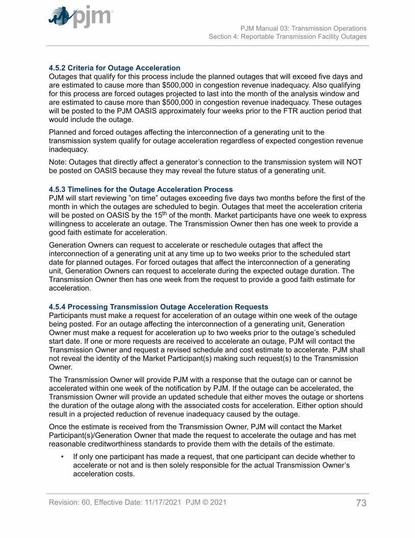
4.5.2 Criteria for Outage AccelerationOutages that qualify for this process include the planned outages that will exceed five days andare estimated to cause more than $500,000 in congestion revenue inadequacy. Also qualifyingfor this process are forced outages projected to last into the month of the analysis window andare estimated to cause more than $500,000 in congestion revenue inadequacy. These outageswill be posted to the PJM OASIS approximately four weeks prior to the FTR auction period thatwould include the outage.Planned and forced outages affecting the interconnection of a generating unit to thetransmission system qualify for outage acceleration regardless of expected congestion revenueinadequacy.Note: Outages that directly affect a generator’s connection to the transmission system will NOTbe posted on OASIS because they may reveal the future status of a generating unit.
4.5.3 Timelines for the Outage Acceleration ProcessPJM will start reviewing ”on time” outages exceeding five days two months before the first of themonth in which the outages are scheduled to begin. Outages that meet the acceleration criteriawill be posted on OASIS by the 15th of the month. Market participants have one week to expresswillingness to accelerate an outage. The Transmission Owner then has one week to provide agood faith estimate for acceleration.Generation Owners can request to accelerate or reschedule outages that affect theinterconnection of a generating unit at any time up to two weeks prior to the scheduled startdate for planned outages. For forced outages that affect the interconnection of a generatingunit, Generation Owners can request to accelerate during the expected outage duration. TheTransmission Owner then has one week from the request to provide a good faith estimate foracceleration.
4.5.4 Processing Transmission Outage Acceleration RequestsParticipants must make a request for acceleration of an outage within one week of the outagebeing posted. For an outage affecting the interconnection of a generating unit, GenerationOwner must make a request for acceleration up to two weeks prior to the outage’s scheduledstart date. If one or more requests are received to accelerate an outage, PJM will contact theTransmission Owner and request a revised schedule and cost estimate to accelerate. PJM shallnot reveal the identity of the Market Participant(s) making such request(s) to the TransmissionOwner.The Transmission Owner will provide PJM with a response that the outage can or cannot beaccelerated within one week of the notification by PJM. If the outage can be accelerated, theTransmission Owner will provide an updated schedule that either moves the outage or shortensthe duration of the outage along with the associated costs for acceleration. Either option shouldresult in a projected reduction of revenue inadequacy caused by the outage.Once the estimate is received from the Transmission Owner, PJM will contact the MarketParticipant(s)/Generation Owner that made the request to accelerate the outage and has metreasonable creditworthiness standards to provide them with the details of the estimate.
• If only one participant has made a request, that one participant can decide whether toaccelerate or not and is then solely responsible for the actual Transmission Owner’sacceleration costs.
PJM Manual 03: Transmission OperationsSection 4: Reportable Transmission Facility Outages
Revision: 60, Effective Date: 11/17/2021 PJM © 2021 73
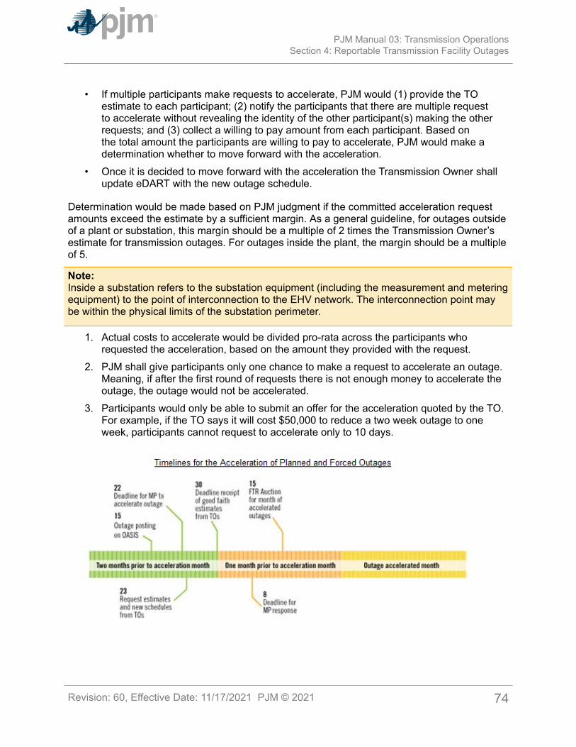
• If multiple participants make requests to accelerate, PJM would (1) provide the TOestimate to each participant; (2) notify the participants that there are multiple requestto accelerate without revealing the identity of the other participant(s) making the otherrequests; and (3) collect a willing to pay amount from each participant. Based onthe total amount the participants are willing to pay to accelerate, PJM would make adetermination whether to move forward with the acceleration.
• Once it is decided to move forward with the acceleration the Transmission Owner shallupdate eDART with the new outage schedule.
Determination would be made based on PJM judgment if the committed acceleration requestamounts exceed the estimate by a sufficient margin. As a general guideline, for outages outsideof a plant or substation, this margin should be a multiple of 2 times the Transmission Owner’sestimate for transmission outages. For outages inside the plant, the margin should be a multipleof 5.
Note:Inside a substation refers to the substation equipment (including the measurement and meteringequipment) to the point of interconnection to the EHV network. The interconnection point maybe within the physical limits of the substation perimeter.
1. Actual costs to accelerate would be divided pro-rata across the participants whorequested the acceleration, based on the amount they provided with the request.
2. PJM shall give participants only one chance to make a request to accelerate an outage.Meaning, if after the first round of requests there is not enough money to accelerate theoutage, the outage would not be accelerated.
3. Participants would only be able to submit an offer for the acceleration quoted by the TO.For example, if the TO says it will cost $50,000 to reduce a two week outage to oneweek, participants cannot request to accelerate only to 10 days.
PJM Manual 03: Transmission OperationsSection 4: Reportable Transmission Facility Outages
Revision: 60, Effective Date: 11/17/2021 PJM © 2021 74
If PJM determines that the acceleration should proceed, PJM will then request that theTransmission Owner moves ahead with the acceleration. All of the financial risks associatedwith the outage acceleration will be borne by those market participants who choose toparticipate in the specific outage acceleration; the Transmission Owner will not be responsiblefor any of these additional costs. If, despite the good faith efforts of the Transmission Owner,the acceleration estimated is exceeded, or the Transmission Owner is not able to successfullycomplete the outage on the accelerated schedule, the market participants will bear the full costof the acceleration.It shall be the responsibility of the Transmission Owner to make every reasonable effort tocontact PJM prior to exceeding the original estimate by 20% of the cost to accelerate todetermine if work should continue at the accelerated schedule or be completed at the originalschedule. PJM will then contact the impacted participant. The participant has two businessdays to decide whether to continue with the revised transmission outage schedule and paythe additional costs. PJM will advise the TO how to proceed based on the feedback from theparticipant.
PJM Manual 03: Transmission OperationsSection 4: Reportable Transmission Facility Outages
Revision: 60, Effective Date: 11/17/2021 PJM © 2021 75

Section 5: Index and Operating Procedures for PJM RTO OperationThe operational procedures have been moved into a new PJM Manual-03B: TransmissionOperating Procedures. The new Manual-03B and its content can be found in the Critical EnergyInfrastructure Information (CEII) page located here:
• http://www.pjm.com/library/manuals/private-m03.aspx
The required access forms are located here:
• http://www.pjm.com/library/request-access.aspx
PJM Manual 03: Transmission OperationsSection 5: Index and Operating Procedures for PJM RTO Operation
Revision: 60, Effective Date: 11/17/2021 PJM © 2021 76
Attachment A: RAS Listing
PJM Manual 03: Transmission OperationsAttachment A: RAS Listing
Revision: 60, Effective Date: 11/17/2021 PJM © 2021 77
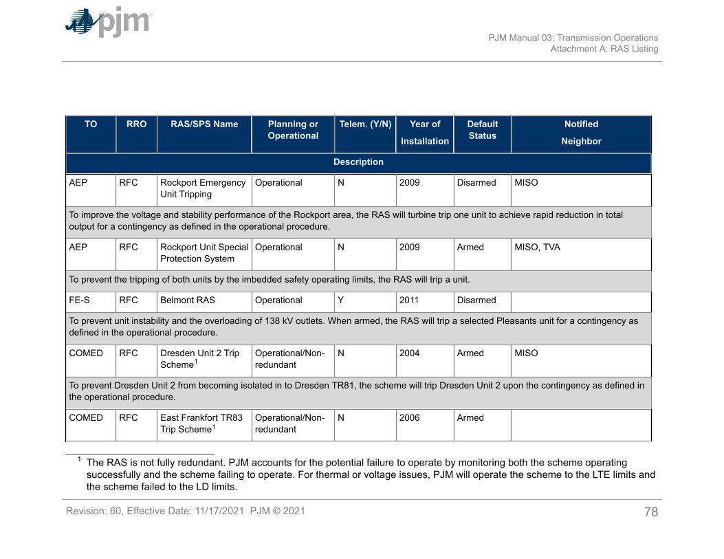
TO RRO RAS/SPS Name Planning orOperational
Telem. (Y/N) Year of
Installation
DefaultStatus
Notified
Neighbor
Description
AEP RFC Rockport EmergencyUnit Tripping
Operational N 2009 Disarmed MISO
To improve the voltage and stability performance of the Rockport area, the RAS will turbine trip one unit to achieve rapid reduction in totaloutput for a contingency as defined in the operational procedure.
AEP RFC Rockport Unit SpecialProtection System
Operational N 2009 Armed MISO, TVA
To prevent the tripping of both units by the imbedded safety operating limits, the RAS will trip a unit.
FE-S RFC Belmont RAS Operational Y 2011 Disarmed
To prevent unit instability and the overloading of 138 kV outlets. When armed, the RAS will trip a selected Pleasants unit for a contingency asdefined in the operational procedure.
COMED RFC Dresden Unit 2 TripScheme1
Operational/Non-redundant
N 2004 Armed MISO
To prevent Dresden Unit 2 from becoming isolated in to Dresden TR81, the scheme will trip Dresden Unit 2 upon the contingency as defined inthe operational procedure.
COMED RFC East Frankfort TR83Trip Scheme1
Operational/Non-redundant
N 2006 Armed
1 The RAS is not fully redundant. PJM accounts for the potential failure to operate by monitoring both the scheme operatingsuccessfully and the scheme failing to operate. For thermal or voltage issues, PJM will operate the scheme to the LTE limits andthe scheme failed to the LD limits.
PJM Manual 03: Transmission OperationsAttachment A: RAS Listing
Revision: 60, Effective Date: 11/17/2021 PJM © 2021 78
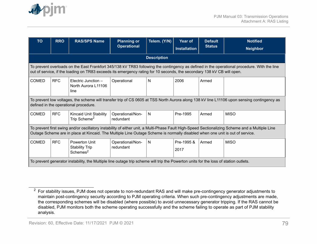
TO RRO RAS/SPS Name Planning orOperational
Telem. (Y/N) Year of
Installation
DefaultStatus
Notified
Neighbor
Description
To prevent overloads on the East Frankfort 345/138 kV TR83 following the contingency as defined in the operational procedure. With the lineout of service, if the loading on TR83 exceeds its emergency rating for 10 seconds, the secondary 138 kV CB will open.
COMED RFC Electric Junction –North Aurora L11106line
Operational N 2006 Armed
To prevent low voltages, the scheme will transfer trip of CS 0605 at TSS North Aurora along 138 kV line L11106 upon sensing contingency asdefined in the operational procedure.
COMED RFC Kincaid Unit StabilityTrip Scheme2
Operational/Non-redundant
N Pre-1995 Armed MISO
To prevent first swing and/or oscillatory instability of either unit, a Multi-Phase Fault High-Speed Sectionalizing Scheme and a Multiple LineOutage Scheme are in place at Kincaid. The Multiple Line Outage Scheme is normally disabled when one unit is out of service.
COMED RFC Powerton UnitStability TripSchemes2
Operational/Non-redundant
N Pre-1995 &
2017
Armed MISO
To prevent generator instability, the Multiple line outage trip scheme will trip the Powerton units for the loss of station outlets.
2 For stability issues, PJM does not operate to non-redundant RAS and will make pre-contingency generator adjustments tomaintain post-contingency security according to PJM operating criteria. When such pre-contingency adjustments are made,the corresponding schemes will be disabled (where possible) to avoid unnecessary generator tripping. If the RAS cannot bedisabled, PJM monitors both the scheme operating successfully and the scheme failing to operate as part of PJM stabilityanalysis.
PJM Manual 03: Transmission OperationsAttachment A: RAS Listing
Revision: 60, Effective Date: 11/17/2021 PJM © 2021 79
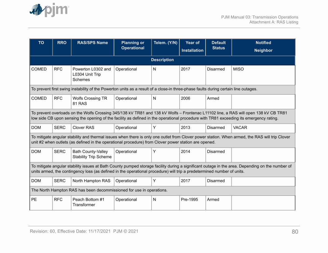
TO RRO RAS/SPS Name Planning orOperational
Telem. (Y/N) Year of
Installation
DefaultStatus
Notified
Neighbor
Description
COMED RFC Powerton L0302 andL0304 Unit TripSchemes
Operational N 2017 Disarmed MISO
To prevent first swing instability of the Powerton units as a result of a close-in three-phase faults during certain line outages.
COMED RFC Wolfs Crossing TR81 RAS
Operational N 2006 Armed
To prevent overloads on the Wolfs Crossing 345/138 kV TR81 and 138 kV Wolfs – Frontenac L11102 line, a RAS will open 138 kV CB TR81low side CB upon sensing the opening of the facility as defined in the operational procedure with TR81 exceeding its emergency rating.
DOM SERC Clover RAS Operational Y 2013 Disarmed VACAR
To mitigate angular stability and thermal issues when there is only one outlet from Clover power station. When armed, the RAS will trip Cloverunit #2 when outlets (as defined in the operational procedure) from Clover power station are opened.
DOM SERC Bath County-ValleyStability Trip Scheme
Operational Y 2014 Disarmed
To mitigate angular stability issues at Bath County pumped storage facility during a significant outage in the area. Depending on the number ofunits armed, the contingency loss (as defined in the operational procedure) will trip a predetermined number of units.
DOM SERC North Hampton RAS Operational Y 2017 Disarmed
The North Hampton RAS has been decommissioned for use in operations.
PE RFC Peach Bottom #1Transformer
Operational N Pre-1995 Armed
PJM Manual 03: Transmission OperationsAttachment A: RAS Listing
Revision: 60, Effective Date: 11/17/2021 PJM © 2021 80
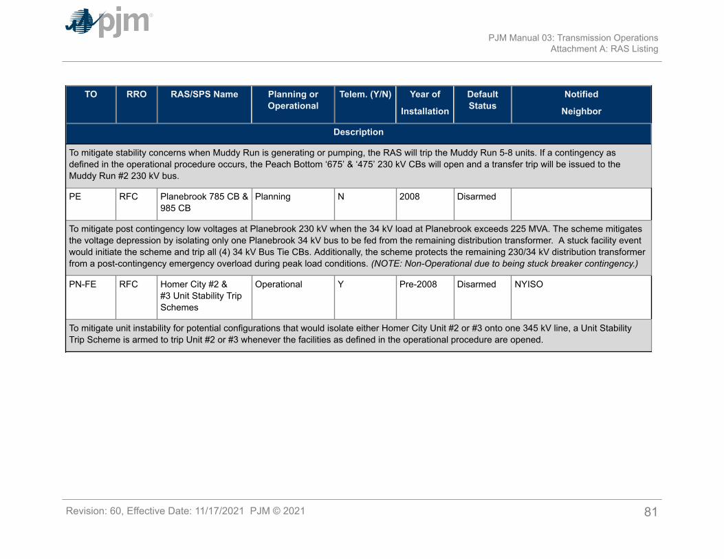
TO RRO RAS/SPS Name Planning orOperational
Telem. (Y/N) Year of
Installation
DefaultStatus
Notified
Neighbor
Description
To mitigate stability concerns when Muddy Run is generating or pumping, the RAS will trip the Muddy Run 5-8 units. If a contingency asdefined in the operational procedure occurs, the Peach Bottom ‘675’ & ‘475’ 230 kV CBs will open and a transfer trip will be issued to theMuddy Run #2 230 kV bus.
PE RFC Planebrook 785 CB &985 CB
Planning N 2008 Disarmed
To mitigate post contingency low voltages at Planebrook 230 kV when the 34 kV load at Planebrook exceeds 225 MVA. The scheme mitigatesthe voltage depression by isolating only one Planebrook 34 kV bus to be fed from the remaining distribution transformer. A stuck facility eventwould initiate the scheme and trip all (4) 34 kV Bus Tie CBs. Additionally, the scheme protects the remaining 230/34 kV distribution transformerfrom a post-contingency emergency overload during peak load conditions. (NOTE: Non-Operational due to being stuck breaker contingency.)
PN-FE RFC Homer City #2  Unit Stability TripSchemes
Operational Y Pre-2008 Disarmed NYISO
To mitigate unit instability for potential configurations that would isolate either Homer City Unit #2 or #3 onto one 345 kV line, a Unit StabilityTrip Scheme is armed to trip Unit #2 or #3 whenever the facilities as defined in the operational procedure are opened.
PJM Manual 03: Transmission OperationsAttachment A: RAS Listing
Revision: 60, Effective Date: 11/17/2021 PJM © 2021 81
Attachment B: Transmission Outage ‘Cut-In’ Ticket GuidelinesThe following guidelines have been created in order to assist the Transmission Owner (TO) indetermining if the ‘cut-in’ flag should be checked when submitting a transmission outage ticketin eDART. It is critical that this flag be used as intended to ensure all new and/or upgradedfacilities/equipment are being accurately monitored and screened for in the PJM EMS.
This attachment will include the high-level criteria for the ‘cut-in’ tickets, followed by somedescriptive examples of tickets that should have the ‘cut-in’ box checked as well as some thatshould not have the ‘cut-in’ box checked. It should be noted, there may be some exceptions andsituations that do not fit entirely into the criteria below. In those instances, please contact PJMTransmission Operations Department for clarification.
‘Cut-In’ Criteria for TOA. All ‘cut-in’ tickets should have a very explicit description of work (i.e., “At the completion ofthis outage, new line xx-xx will be energized”). This is especially important so all PJM users ofeDART can have a clear picture of what equipment/facilities need to be updated in the PJMEMS.B. When possible, future equipment should be included in the ‘cut-in’ ticket if already in thePJM model. If new equipment is not available in eDART, ‘description of work’ comments shouldinclude this information so PJM staff can enter the new equipment once it is modeled.C. There should only be one ‘cut-in’ ticket per facility being energized. The assumption is, at thereturn of the ticket, the cut-in facility will be in service. Other tickets that support the constructionof the final energized facility (i.e., outages supporting intermediate phases of construction)should NOT be marked cut-in. In such cases, it is preferred that each ticket indicate which oneis the final cut-in ticket (i.e. ticket 1 of 2, final cut-in occurs on eDART #999999).D. If any cut-in is associated with a project and/or there are additional ‘cut-in’ tickets related to it:
1. An outage sequence should be attached to EACH cut-in ticket and a ‘project’ should becreated in eDART for help with tracking the tickets together. This can be coordinatedwith outage analysis contacts at PJM.
2. When possible all ‘cut-in’ ticket numbers associated with a project should be listed in the‘description of work’ to allow the ability to cross-reference information.
E. PJM ‘cut-in’ tickets generally DO fall into one of the following categories:1. Any new branch (line, transformer, series device, phase shifter) or shunt that will affect
PJM modeled topology.2. Any reconfiguration (circuit breakers, disconnects, bus topology changes).3. Any reconductored/upgraded equipment that will result in a different rating and/or
impedance change when re-energized (i.e., CT/PT, wave trap).4. Permanently retiring facilities (should be explicitly noted in description of work).
F. PJM ‘cut-in’ tickets generally DO NOT fall into the following categories:1. Replace/repair existing equipment that will not change ratings or topology (i.e., CT/PT,
wave trap, distribution transformer).
PJM Manual 03: Transmission OperationsAttachment B: Transmission Outage ‘Cut-In’ Ticket Guidelines
Revision: 60, Effective Date: 11/17/2021 PJM © 2021 82
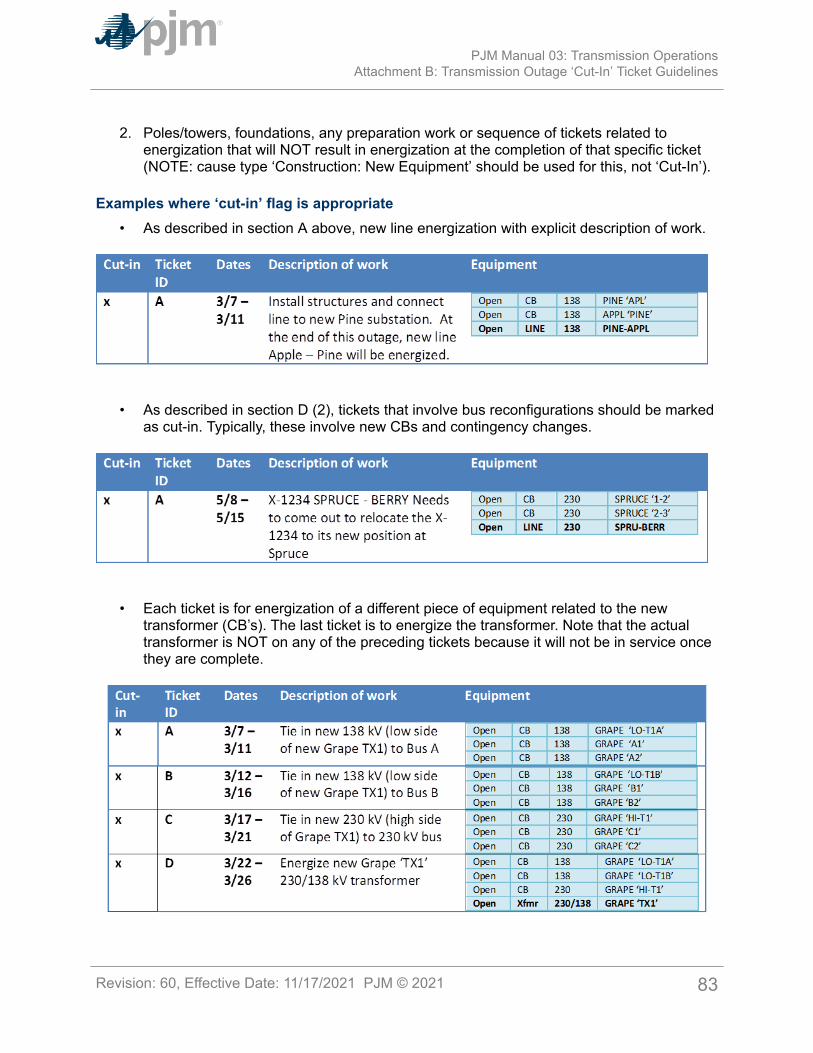
2. Poles/towers, foundations, any preparation work or sequence of tickets related toenergization that will NOT result in energization at the completion of that specific ticket(NOTE: cause type ‘Construction: New Equipment’ should be used for this, not ‘Cut-In’).
Examples where ‘cut-in’ flag is appropriate• As described in section A above, new line energization with explicit description of work.
• As described in section D (2), tickets that involve bus reconfigurations should be markedas cut-in. Typically, these involve new CBs and contingency changes.
• Each ticket is for energization of a different piece of equipment related to the newtransformer (CB’s). The last ticket is to energize the transformer. Note that the actualtransformer is NOT on any of the preceding tickets because it will not be in service oncethey are complete.
PJM Manual 03: Transmission OperationsAttachment B: Transmission Outage ‘Cut-In’ Ticket Guidelines
Revision: 60, Effective Date: 11/17/2021 PJM © 2021 83
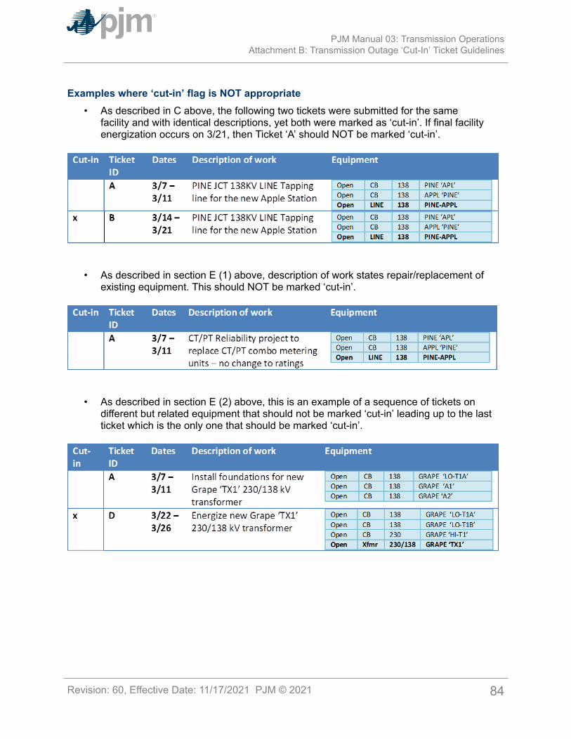
Examples where ‘cut-in’ flag is NOT appropriate• As described in C above, the following two tickets were submitted for the same
facility and with identical descriptions, yet both were marked as ‘cut-in’. If final facilityenergization occurs on 3/21, then Ticket ‘A’ should NOT be marked ‘cut-in’.
• As described in section E (1) above, description of work states repair/replacement ofexisting equipment. This should NOT be marked ‘cut-in’.
• As described in section E (2) above, this is an example of a sequence of tickets ondifferent but related equipment that should not be marked ‘cut-in’ leading up to the lastticket which is the only one that should be marked ‘cut-in’.
PJM Manual 03: Transmission OperationsAttachment B: Transmission Outage ‘Cut-In’ Ticket Guidelines
Revision: 60, Effective Date: 11/17/2021 PJM © 2021 84
Attachment C: Requesting Voltage Limit Exceptions to the PJMBaseline Voltage Limits
The purpose of this attachment is to provide further explanation on how to request voltage limitexceptions for non-PJM OATT facilities to the PJM Baseline Voltage Limits as discussed in thisManual Section 3: Voltage and Stability Operating Guidelines.
Addressing Generators and other Non- PJM OATT Facilities (including Distribution) (seeExhibit C-1)
1. For a limitation at a Generator or other Non- PJM OATT facility, a PJM Member canrequest PJM to operate for any requested voltage limits at a specific bus that areidentified as more restricting than the PJM Baseline Voltage Limits.a. These requested voltage limits are submitted in writing by the PJM Member to the
PJM Manager – Transmission Operations Department.b. PJM will evaluate these limits for reasonableness and inform the requestor.
2. The PJM Member will be billed for any “Off-cost” operation.
Note:For NPIR voltage limits, PJM will notify the impacted Transmission Owner and coordinate theimplementation.
To: PJM Manager-Transmission Operations DepartmentFrom: PJM Member Company:___________________ Requested By: _________________RE: Request to Operate to a Different Voltage Limit than the PJM Baseline Voltage Limits for aGenerator or Other Non-PJM Open Access Transmission Tariff Facility.We request that PJM operate to a voltage limit different from the PJM Baseline Voltage Limitsat the specific bus identified below. If this bus limitation results in “off-cost” operation appropriatebilling will be made to the PJM Member/Requestor.Authorized by: _______________ (PJM Member Representative) Date: _______
FacilityIdentification
Voltage LD EL NL NH %VoltDrop
TargetImplementation
Date
Comment orReason for
voltage limitexception to the
PJM BaselineLimit
PJM Manual 03: Transmission OperationsAttachment C: Requesting Voltage Limit Exceptions to the PJM Baseline Voltage
Limits
Revision: 60, Effective Date: 11/17/2021 PJM © 2021 85
Key: LD = Load Dump EL = Post Contingency Emergency Low NL = Normal Low NH = High % Volt Drop = Post ContingencyVoltage Drop Percentage Limit
Exhibit C-1Submit this form to the PJM Manager-Transmission Operations Department([email protected]). Attach other pertinent documentation that would provide a completeunderstanding of the reason for the request. PJM will contact the requestor with feedback onthe status of this request or any questions. If you have any questions, please call the Manager-Transmission Operations Department at (610) 666-8976. PJM will communicate, coordinateanalysis, and implementation dates with the impacted Transmission Owners(s).
PJM Manual 03: Transmission OperationsAttachment C: Requesting Voltage Limit Exceptions to the PJM Baseline Voltage
Limits
Revision: 60, Effective Date: 11/17/2021 PJM © 2021 86
Attachment D: Post Contingency Congestion Management ProgramPJM has historically operated on a pre-contingency basis under which it calls for off-costgeneration to be run to alleviate contingency overloads. The amount of off- cost generationcan total in excess of millions of dollars per year in congestion. PJM analysis indicates that theprobability of contingent facility tripping during an off-cost event is less than .05%.
PJM believes that it is prudent to operate to a higher pre-contingency threshold (i.e., 30-minuterating) in areas where analysis demonstrates that there is ample fast-start generation orswitching actions available to eliminate an actual overload should contingent facility trippingoccur. This generation must demonstrate a history of adequate availability and response asdefined below.
PJM’s post-contingency congestion management program is operated for monitored facilitiesthat meet the following criteria:
1. Outage of the contingent facility must not cause a cascading outage or precipitateuncontrolled separation within and external to the PJM Balancing Authority.
2. EHV facilities will not be included in this program. However there are cases in someareas where facilities up to and including 345 kV may be studied for inclusion in theprogram as long as there is no adverse impact on the transmission system.
3. The Transmission Owner of the facility will have established a short-term emergencyrating for the facility (nominally 30 minutes).
4. Facilities must have more than one fast-start combustion turbine or diesel generator inthe vicinity (and off-line) to eliminate a contingency should it occur. Normally, availabilityof 120% of the necessary generation to obtain the required MW relief from the 30-minuterating to normal rating will need to be demonstrated to account for the possibility thatsome generation will not start.
5. The net area generation has to have a history of being on-line and loaded for controlwithin 30 minutes 85% of the time. (Normally, review of the previous 12 monthperformance will be sufficient to establish the historical performance.)
6. Where available, condensers will be brought on-line for control once contingency flowreaches the 4-hour emergency rating.
7. This program will be implemented during non-winter months for facilities where fast-startgeneration is used for control. Switching procedures that demonstrate successful winterimplementation may be included under the program year-round.
8. Facilities in transmission systems that were designed to operate on a post-contingencybasis as outlined in the next section will be considered on a case by case basis.
Alternative Controlling Options1. The TO may offer generation run-back schemes to control for these facilities. These will
be considered as controlling actions under this program after PJM tests the ramp-ratedata as supplied by the generation owner. Further discussion and analysis is neededin this area prior to accepting these options. This document will be revised once theseprocedures are submitted, tested, and approved.
PJM Manual 03: Transmission OperationsAttachment D: Post Contingency Congestion Management Program
Revision: 60, Effective Date: 11/17/2021 PJM © 2021 87
2. The TO may offer switching and reclosing procedures to control for these facilities inaccordance with applicable regional requirements. These procedures must be studiedand approved by PJM. These procedures may be implemented once PJM has thecapability to properly study the impacts of these options in EMS.
Transmission Owners (TOs) must be capable of implementing the agreed upon post-contingency switching procedures via SCADA control. Additionally, TOs must have the ability todump sufficient load via SCADA in the event that switching procedures cannot be implemented.Load dump cannot propagate to adjacent zones.Where feasible, the switching procedures mentioned above may be implemented on a pre-contingency basis once contingency flow exceeds the 30-minute rating and all controllinggeneration has been called.Systems Designed for Post-Contingency Switching
1. On a pre-contingency basis off-cost operations will commence once simulatedcontingency flow, using guide implemented contingency definitions, reaches the long-term emergency (LTE) rating.
2. On a pre-contingency basis off-cost operations will commence once simulatedcontingency flow, using guide failed contingency definitions, approaches the load dump(LD) rating.
3. In the event of a contingent facility tripping, the appropriate guide scheme will be used toensure flow drops below the LTE rating on the monitored facility. If the post-contingencyoperating step does not reduce flow below the normal rating on this facility, generationre-dispatch, where available, will be used to bring flow below the normal rating.
Roles and Responsibilities1. PJM. PJM will be responsible for selecting the facilities for inclusion into the program
and performing the required analysis to ensure that the facilities meet the criteriafor participation. PJM will consult with and communicate with the appropriate TO, asrequired, to ensure that the analysis is accurate. PJM will publish the list of facilities inPJM Manual M-03, Transmission Operations and will operate to the short term ratingprovided by the TO. If the rating is exceeded pre-contingency, PJM will operate off-costto mitigate the simulated overload.
2. Transmission Owner. The TO will review and comment on the facilities proposed underthis program. If the TO disagrees with a proposed facility they may take that facility to thePJM Dispute Resolution Process and PJM will delay implementation of that facility intothe program until the completion of the process. The TO may offer additional facilitiesto be studied for inclusion under this program. The TO is responsible for establishing ashort term rating for these facilities. These ratings will be submitted to PJM for approval.The TO will provide the necessary information to PJM to enable the appropriate analysis.
3. Generation Owner. The owners of the fast-response generation are to operate thoseunits is accordance with the current PJM rules and procedures. When called upon tomitigate a transmission outage on a facility included in the program, the generationowner shall start the unit in accordance with PJM’s instructions.
PJM Manual 03: Transmission OperationsAttachment D: Post Contingency Congestion Management Program
Revision: 60, Effective Date: 11/17/2021 PJM © 2021 88
Process for TO to Request PJM to Change constraints/facilities in the Post-ContingencyCongestion Management program
1. By Dec 1 - TO formally submits the request, addressed to the Manager of TransmissionOperations, for PJM to change the transmission constraints/facilities in the Programstarting June 1 of the following year. TO should provide all necessary information withthe request for PJM to perform the required analysis.
2. Shortly after Dec 1 - PJM posts all pending requests (including those selected by PJMand those requested by Transmission Owners) on the PJM website shortly after the Dec1 submittal deadline.
3. Dec 1 to Feb 15 - PJM System Planning, System Operations, Performance Complianceand Market Monitoring Departments perform various studies to determine if thetransmission constraint can be accepted in the Program.
4. Mar 1 - TO will be notified whether the requested transmission constraint can beaccepted in the Program.
5. Mar 1 to Mar 8 - PJM posts the changes to the constraint list in the Program effectiveJune 1 on the PJM website. PJM will indicate whether the constraint is accepted fornon-Winter months only or for the year-round.
6. Jun 1 - PJM assumes the operation of the transmission constraints under the Program.
Note:This process has the same timeline as the Process to Change the PJM CongestionManagement Control Facilities List as stated in Section 1 of this Manual.
Post-Contingency Congestion Management Program Constraint ListThere are no transmission constraints included in the operation of the Post ContingencyCongestion Management Program.
PJM Manual 03: Transmission OperationsAttachment D: Post Contingency Congestion Management Program
Revision: 60, Effective Date: 11/17/2021 PJM © 2021 89
Attachment E: Automatic Sectionalizing SchemesList of currently active Automatic Sectionalizing Schemes is posted on OASIS at this link:
https://www.pjm.com/-/media/etools/oasis/system-information/manual-03-attachment-e-automatic-sectionalizing-schemes.ashx?la=en
Automatic Sectionalizing Schemes pending approval and recent changes are posted on OASISat this link:
https://www.pjm.com/-/media/etools/oasis/system-information/manual-03-attachment-e-automatic-sectionalizing-schemes-pending-approval-and-recent-changes.ashx?la=en
PJM Manual 03: Transmission OperationsAttachment E: Automatic Sectionalizing Schemes
Revision: 60, Effective Date: 11/17/2021 PJM © 2021 90

Attachment F: Short Term Emergency RatingsThe referenced attachment lists facilities with STE Ratings and their appropriate time baseddurations (30-minutes, 2hrs, etc). The STE ratings are used on a post-contingency basis inconjunction with operating steps listed in Manual-03 Section 5 or Attachment D as special casesto control for an actual overload as defined in Section 2 and Exhibit 1. If no associated operatingstep exists or the associated operating step does not reduce the loading to below the LTErating, the duration of the rating is utilized to determine the time to shed load.
The STE rating list is posted on OASIS at this link:
http://www.pjm.com/~/media/etools/oasis/system-information/m03-attachment-f-ste-rating-list.ashx
PJM Manual 03: Transmission OperationsAttachment F: Short Term Emergency Ratings
Revision: 60, Effective Date: 11/17/2021 PJM © 2021 91
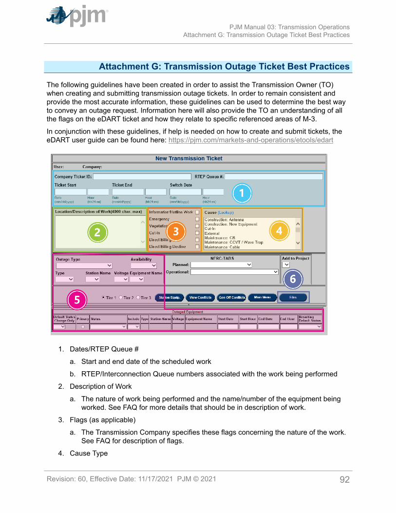
Attachment G: Transmission Outage Ticket Best Practices
The following guidelines have been created in order to assist the Transmission Owner (TO)when creating and submitting transmission outage tickets. In order to remain consistent andprovide the most accurate information, these guidelines can be used to determine the best wayto convey an outage request. Information here will also provide the TO an understanding of allthe flags on the eDART ticket and how they relate to specific referenced areas of M-3.
In conjunction with these guidelines, if help is needed on how to create and submit tickets, theeDART user guide can be found here: https://pjm.com/markets-and-operations/etools/edart
1. Dates/RTEP Queue #
a. Start and end date of the scheduled work
b. RTEP/Interconnection Queue numbers associated with the work being performed
2. Description of Work
a. The nature of work being performed and the name/number of the equipment beingworked. See FAQ for more details that should be in description of work.
3. Flags (as applicable)
a. The Transmission Company specifies these flags concerning the nature of the work.See FAQ for description of flags.
4. Cause Type
PJM Manual 03: Transmission OperationsAttachment G: Transmission Outage Ticket Best Practices
Revision: 60, Effective Date: 11/17/2021 PJM © 2021 92
a. Generic classification of work being performed
5. Equipment/Availability
a. Tabular list of equipment and facilities to be operated or unavailable during theoutage
b. Switching times (if different from ticket start/end)
c. Availability of returning the outage before completion (for emergency purposes)
6. Attachments (optional)
a. Additional files for PJM operators to better understand the nature of the work
FAQ when creating transmission outage tickets:1. Dates/RTEP/Queue
a. How should I enter times for equipment that will be open for switching only?
i Please use the equipment status options of ‘takeout’, ‘restore’, and ‘takeout andrestore’ for this function.
b. How should I handle outages that have equipment coming out ‘one a time?’
i Ideally have one ticket with individual times listed at the equipment level for eachpiece of equipment. Please explicitly mention that the work is to be done one at atime in the ‘Description of Work’ field. ‘One at a time’ tickets should:
• Have only ONE substation per ticket
• Not cover more than one day (24 hour period) per ticket
c. Do I have to enter anything in the RTEP field?
i This field is reserved for any RTEP/Interconnection Queue numbers associatedwith the work being performed. If this information is available, it is very helpful forcross-reference/cross-divisional purposes and assistance with modeling of newequipment. RTEP/Interconnection Queue numbers can also be entered in theDescription of Work.
2. Description of Worka. What should be included in the ‘Description of Work’ field?
i The information in this field should be clear and concise and should include anyor all of the following as they apply:
• The nature of work being performed
• The name/number of the equipment being worked on, including anyequipment needed for takeout/restore, to ensure that the correctequipment has been selected from the equipment list
• Any needed contingency switching to account for congestion
• Any cross-referenced/related tickets that should be noted (i.e. cut-intickets or other tickets associated with a project sequence)
PJM Manual 03: Transmission OperationsAttachment G: Transmission Outage Ticket Best Practices
Revision: 60, Effective Date: 11/17/2021 PJM © 2021 93
• Any special procedures that may/will be implemented during the ticket
• Whether any NEW equipment will be energized AND/OR retired uponcompletion of this ticket (typically the ‘cut-in’ flag will be checked in thiscase Refer to Flags section in this document and Attachment B in thismanual for more information.
• Any additional useful information that cannot be conveyed in other areasof the ticket
• If the equipment is unavailable to select in eDART, there should be anote in the description of work with the specific name of the equipmentthat should be included on the ticket. Refer to Equipment section in thisdocument for more information.
b. Is all of the information listed above required?
i While these are just guidelines and not required, this field provides the TO theopportunity to convey as much detail as possible in order to ensure the outageis studied appropriately. If this field is not populated sufficiently, the ticket may beflagged as ‘potentially incomplete’ (see Flags section in this document)
3. Flagsa. What is the purpose of each flag available to the transmission company?
i Emergency - This flag should be checked by the TO if the work is emergent andcannot wait for proper on-time submittal. It should be noted that once this flag ischecked, the ticket may be open to additional review to ensure the emergencystatus is being used properly. Refer to Section 4.2.8 in this manual for additionalinformation.
ii Cut-in Flag - This flag should be checked by the TO if completion of the ticket willresult in any new energization, retired equipment, and/or a change in parameterssuch as impedance and ratings. Refer to Attachment B in this manual foradditional information
iii Direct Billing/Direct Billing decline - Use of this flag applies to tickets that areNOT ON TIME for which congestion is expected. Any time this flag is checked, itshould be done so in conjunction with coordination with PJM outage coordinationcontacts. Refer to Section 4.2.9.1 in this manual for additional information.
iv Info Hotline Work - This flag should be checked by the TO for in-service work.Refer to Section 4.2.2 in this manual for additional information.
v Veg Trip - This flag should be checked by the TO if the nature of the work isfor vegetation. Note that use of the Cause Type – ‘Maintenance: Vegetation’ willresult in this flag being automatically checked.
b. What are the additional flags unavailable to transmission owners?
i Submit On-Time (automatic or PJM Personnel*) - This flag is checked/un-checked using built in logic within eDART based on PJM outage submittal rules.PJM personnel also have a tool which can tell if rescheduling a ticket impactsit’s on-time status; contact your PJM outage coordination contact if you want
PJM Manual 03: Transmission OperationsAttachment G: Transmission Outage Ticket Best Practices
Revision: 60, Effective Date: 11/17/2021 PJM © 2021 94
to evaluate if a ticket gains/losses on-time status if you were to reschedule it.Refer to Section 4.2.1 in this manual for additional information. *PJM personnelmay check the flag at their discretion and in coordination with the TO whencircumstances indicate it is warranted.
ii Potentially Incomplete (automatic) - This flag may be checked by eDART if theinformation in the ‘Description of Work’ field is insufficient. (See ‘Description ofWork’ section in this document for more information)
iii Market Sensitive (automatic) - This flag may be checked by eDART if any ofthe equipment selected for the ticket is associated with a generator. The marketsensitive equipment will not be publicly posted on OASIS.
iv Congestion Expected (added by PJM personnel) - This flag will be checkedby the PJM Outage Analysis Team in conjunction with subsequent informationdetailed in the ‘PJM Comments’ field. While the flag is checked if congestion isencountered during analysis, there are additional reasons for which this flag maybe used to draw attention to the ticket. Reasons include but are not limited to:
• Contingency activation/de-activation needed
• Contingency switching solution needed
• Modeling issues/concerns with the ticket
• Capacitor switching indicated
v At Risk (added by PJM personnel) - This flag will be checked by the PJM OutageAnalysis Team (often during the six month out/one month out analysis timeframe)whenever there is uncertainty on whether the outage can be completed on thedates requested. This can be due to:
• Load Dependent – in this case, typically the flag remains checked until thenear-term analysis is completed with more accurate load projections
• Conflicts with other outages submitted during the same timeframe –details will be provided in the PJM comments field and conflicts shouldbe resolved in coordination with the PJM Outage Analysis Team and otheraffected TO’s as necessary.
4. Cause Typea. How do I know what Cause Type to select for my outage?
i Please refer to the following link for a list of Cause Type definitions whenentering eDART tickets. https://www.pjm.com/-/media/committees-groups/forums/edart/edart/20161202/20161202-transmission-outage-cause-types.ashx?la=en
5. Equipment/Availabilitya. What should I choose as primary equipment?
i The TO should choose the main equipment that is being worked on for theoutage. (i.e. a transmission line or transformer) Any supporting equipment likecircuit breakers/disconnects for clearance should be listed subsequently.
PJM Manual 03: Transmission OperationsAttachment G: Transmission Outage Ticket Best Practices
Revision: 60, Effective Date: 11/17/2021 PJM © 2021 95
b. Should Transmission Owners enter any default status information for equipmentwhen entering their ticket?
i NO, default status equipment is entered by PJM personnel ONLY.
c. What equipment should be included for a line I am taking out of service?
i For a line coming out of service completely, listed equipment should includethe line as well as all clearance points. (i.e. any associated circuit breakers/disconnects that will be out of service for clearance)
d. How should I enter equipment if a line will only be open-ended?
i Please use the ‘open-ended’ equipment status option for this function. Persection 4.2.1 in this manual: "All line and transformers that will be outaged oropen ended as a result of the scheduled maintenance must be included in theoutage request. For example, an outage request for CB work that open ends aline must include the line as being out of service in the ticket. This will ensureproper posting of all outages to the PJM OASIS and the NERC System DateExchange (SDX) site.
e. "What if I have to change/add/delete some of the equipment on my ticket after it hasbeen submitted?
i Once an outage is submitted, some changes to equipment might be needed.It is important to note that the outage is subject to additional scrutiny if initialequipment is changed/deleted and/or new equipment is added to ensure thescope of work has not been changed. If the changes are so extensive that it willchange the scope of work, it is suggested that an additional supporting ticket becreated with a cross-referenced note in the ‘Description of Work’ field.
f. What if I see a message that says ‘This ticket has been locked by PJM’?
i Once a ticket has been moved to ‘approved’ status and/or if any default statusequipment changes have been made to the ticket by PJM personnel, the TO willno longer be able to make changes directly to the ticket. If changes are needed,the TO will have to contact PJM in order to request any changes.
g. What if the ‘availability’ of return for my outage is variable at different times during theoutage?
i Upon entering the ticket, please select the initial/starting availability for theoutage. It should be noted in the ‘Description of Work’ field that the availability forthis outage will be variable. This information should also be communicated to thePJM outage analysis contact. Once the outage has begun, the TO should contacttheir PJM counterpart to request the ‘availability’ status be updated accordinglythroughout the duration of the outage.
h. What if the equipment being worked on is not yet available in eDART?
i If the equipment coming out of service is not modeled in PJM (not available ineDART), a similar equipment should be chosen and a note should be addedto the description stating the equipment is not available in PJM. The actual
PJM Manual 03: Transmission OperationsAttachment G: Transmission Outage Ticket Best Practices
Revision: 60, Effective Date: 11/17/2021 PJM © 2021 96
equipment should be mentioned in the description so that it can be added whenavailable.
6. Attachmentsa. What attachments should be included with an eDART ticket?
i This feature can be used for any outage tickets that are associated with projectsand/or ‘cut-in’ tickets to highlight changes being made. Examples of attachmentsinclude: one-line diagrams and project sequences. Attachments are not requiredand are not needed for all eDART tickets, but can be helpful to provide additionalinformation on the outage.
PJM Manual 03: Transmission OperationsAttachment G: Transmission Outage Ticket Best Practices
Revision: 60, Effective Date: 11/17/2021 PJM © 2021 97
Revision HistoryRevision 59 (05/27/2021):
• Periodic Review:
• Section 1.7: Removed applicability date and added email contact and timeline
• Section 3.4.2 and 3.5.4: NPIR changes for eDART nuclear voltage limits.
• Section 4.2.9: Added clarification language for rescheduling outages longer than 30 daysinto a different planning year.
• Added new Attachment G: Transmission Outage Ticket Best Practices
Revision 58 (11/19/2020):• Periodic Review: Updated references to Manual-03B throughout.
• Section 3.3.1: Corrected 138 kV PJM Baseline limit.
• Section 1, 3, and 4: Updated EHV reference by defining EHV and removed duplicateuses.
Revision 57 (05/29/2020):• Periodic Review
• Corrected typos, removed references to SPS. Updated references to Section 5.
o Moved the contents of Manual-03 Section 5 to a new Manual-03B: TransmissionOperating Procedures.
• Section 1.5: Removed Section 2 reference from Manual 3A.
• Section 1.7: Updated RAS procedure for PRC-012 standard.
• Section 3 and Attachment C: Updated baseline voltage tables and voltage exceptionrequest due to new eDART function for voltage limit implementation.
• Section 3.9: Removed language concerning TSA Benchmarking.
• Section 3.11: Effective June 1, 2020, eDART Voltage Schedules is the required methodfor communicating generator voltage schedules.
• Section 4.5: Added Outage Acceleration posting site and contact email.
• Section 5: Updated RTO Perry and Calvert Cliffs NPIR voltage limits.
• Section 5: Updated NY/NJ PAR Coordination and deleted 5018 Hopatcong – RamapoPAR Coordination in RTO based on updated Joint Operating Memo (OM 022B Market toMarket Redispatch Flowgates and NY NJ PAR Coordination, Rev. 10).
• Section 5: Updated AE directional ratings table.
• Section 5: Updated AEP Jacksons Ferry SVC Procedure.
• Section 5: Removed AEP Cook Stability Restriction Procedure.
• Section 5: Updated FE-S Belmont RAS Procedure.
PJM Manual 03: Transmission OperationsRevision History
Revision: 60, Effective Date: 11/17/2021 PJM © 2021 98
• Section 5: Updated FE-E Seneca Stability Procedure with updated limits.
• Section 5: Added new FE-E Ironwood Stability Procedure.
• Section 5: Updated FE-E Homer City Stability Trip procedure.
• Section 5: Updated BGE Calvert Cliffs Stability Limit Procedure.
• Section 5: Deleted BGE Westport Breaker Limitations and Gould St. GenerationOperations procedure.
• Section 5: Removed ComEd Lisle substation from Normally Open Bus Tie procedures.
• Section 5: Updated language to use RAS for the ComEd Electric Junction – NorthAurora procedure and modified location of CS 0605 to be at 11106 line
• Section 5: Updated ComEd Camp Grove Islanding (SPOG 2-40) procedure for newconfiguration.
• Section 5: Updated the ComEd Powerton Stability Trip Scheme procedure due to thenew Nevada substation.
• Section 5: Updated the ComEd Islanding Prevention Scheme for TSS 941 Grand RidgeGeneration (SPOG 2-41) procedure.
• Section 5: Updated ComEd Prospect Heights SVC procedure.
• Section 5: Added new Lancaster Automatic Trip Scheme to Prevent Islanding ofEcogrove procedure.
• Section 5: Updated powerflow/SA language for the DOM Northern Virginia High VoltageControl procedure.
• Section 5: Added new DOM Mosby/Mt. Storm SVC procedure and Colington STATCOMprocedure.
• Section 5: Added new DOM Ladysmith/Doswell Stability Procedure.
• Section 5: Updated DOM Brunswick/Greensville Stability procedure.
• Section 5: Added new PECO Conowingo stability procedure.
• Section 5: Added new PPL Safe Harbor Relay procedure.
• Section 5: Updated PPL Martins Creek stability procedure.
• Section 5: Updated PSEG Artificial Island procedure due to new substation.
• Attachment A: Updated language for Wolfs Crossing RAS.
• Attachment A: Removed two Lisle schemes due to station reconfiguration.
• Attachment B: Added clarifying language to ‘Cut-In’ Criteria for TO associated withproject work.
Revision 56 (12/05/2019):• Periodic Review.
• Section 1.1: Updated TOP distinction.
PJM Manual 03: Transmission OperationsRevision History
Revision: 60, Effective Date: 11/17/2021 PJM © 2021 99
• Section 1.7: Updated PJM Procedure to Review Remedial Action Schemes/SpecialProtection Systems (RAS/SPS) to remove mention of Special Protection Systems (SPS).
• Section 3.2: Updated voltage drop reference as a percentage of pre kV by removingreference to nominal voltage.
• Section 3.5.3: Updated EHV capacitors in auto mode.
• Section 3.7 – Added additional lines to Dominion area for High Voltage Control.
• Section 4.2.12: Removed Nuclear Generating Station’s Circuit Breaker listing table.
• Section 4.3.2: Updated language in Real-Time Switching notification procedure to betteralign with dispatch switching practices.
• Section 5: Updated the RTO Recognition of Automatic Sectionalizing Schemesprocedure.
• Section 5: Updated Dresden NPIR voltage limits and removed EMS bus node names.
• Section 5: Removed TMI NPIR limits due to unit retirement.
• Section 5: Updated Bi-Directional Ratings for AE.
• Section 5: Updated Bi-Directional Ratings for DPL.
• Section 5: Removed reference to Darwin in the header of the AEP Rockport procedure.
• Section 5: Updated AEP Tidd 138 KV switchyard operating guideline for Overduty CircuitBreakers.
• Section 5: Moved Dayton Darby procedure to AEP.
• Section 5: Updated AEP Cook Plant stability procedure.
• Section 5: Added Jacksons Ferry SVC procedure to AEP.
• Section 5: Added description of conditions for the 2345 circuit for the BGE 230 kVHarbor Crossing Cables procedure.
• Section 5: Updated ComEd Burnham – Taylor 345 kV Line Operation (SPOG 3-6).
• Section 5: Updated ComEd Transformer Operations at 138 kV Line Tie BreakerSubstations (SPOG 4-30).
• Section 5: Updated ComEd SPOG 2-2-B Marengo procedure.
• Section 5: Updated ComEd SPOG 2-2-C Damen procedure.
• Section 5: Added ComEd Prospect Heights SVC procedure (SPOG 2-45).
• Section 5: Removed ComEd Itasca 138 kV N.O. Bus Tie 2-3 CB SPOG 2-37.
• Section 5: Removed ComEd Quad Cities/Cordova RAS/SPS procedure due toretirement.
• Section 5: Updated DOM Bath County Stability restriction for Valley-Dooms 500kV.
• Section 5: Updated Circuit Breaker name for Gordonsville Bus Tie under South Annaand Louisa CT Islanding Scheme.
PJM Manual 03: Transmission OperationsRevision History
Revision: 60, Effective Date: 11/17/2021 PJM © 2021 100
• Section 5: Updated Glebe-VirginiaHills-Ox line reference from 2159A to 248 and addedline #294 for parallel Braddock-Annandale in the Northern Virginia High Voltage Controlprocedure.
• Section 5: Removed Lexington Area Loss-of-Load Contingency Mitigation Proceduredue to additional Dooms-Lexington 2168 line.
• Section 5: Removed PPL Martins Creek Overdutied breaker procedure.
• Section 5: Added new PPL Wescosville 500/138 kV T3 Transformer Switchingprocedure.
• Section 5: Updated the UGI/PPL 66 kV Tie Line Operation procedure.
• Section 5: Updated FE EAST Conemaugh/Hunterstown/Fairview Stability Limitsprocedure.
• Section 5: Updated FE EAST Homer City #2 & #3 Stability Trip (RAS) unit output armingcriteria.
• Section 5: Updated FE EAST Homer City Stability Limits single outage dampingrestrictions.
• Section 5: Updated FE EAST Seneca Stability procedure.
• Section 5: Updated FE EAST Seneca Pumping Notification Procedure (title only).
• Attachment A: Removed the Quad Cities Unit Stability Trip Scheme.
• Attachment A: Removed the Cordova /Quad Cities Multi-Line-Outage Unit Trip Scheme.
• Attachment A: Updated North Hampton RAS description based on future retirement.
• Attachment B: Replaced cause type from ‘New Construction’ to ‘Construction: NewEquipment’ to align with eDART.
Revision 55A (10/31/2019):• Section 5: Deleted Gas-Pipeline Contingency Analysis Procedure
Revision 55 (05/31/2019):• Cover to cover periodic review. Updated links and terminology throughout.
• Section 3.3: Added NextEra to Voltage Limit table.
• Section 3.9: Added language for TSA real-time monitoring and control for dynamicstability.
• Section 4.2.2: Added on-time criteria for hotline work that may have system impact and aclarification note concerning RTU outages not requiring an eDART ticket.
• Section 5: Updated RTO NPIR Voltage limits for North Anna, Surry, and Peach Bottom.Clarified Susquehanna voltage.
• Section 5: Removed the ComEd Dresden Bus Operation procedure.
• Section 5: Updated the ComEd Powerton Stability procedure.
PJM Manual 03: Transmission OperationsRevision History
Revision: 60, Effective Date: 11/17/2021 PJM © 2021 101
• Section 5: Updated the ComEd Normally Open Bus Tie procedure.
• Section 5: Removed the ComEd/MISO Pleasant Prairie-Zion Conservative Operationprocedure.
• Section 5: Removed the FE West Mansfield Unit 2 Reclosing Restriction.
• Section 5: Updated the FE EAST Hunterstown/Conemaugh stability procedure for theinterconnection of the Fairview CC.
• Section 5: Updated the FE East Birdsboro Plant Stability Restriction.
• Section 5: Updated the AEP Rockport operating guide limits.
• Section 5: Removed the AEP Conesville 345 kV plant procedure.
• Section 5: Added new FE East Asylum/Liberty Stability procedure.
• Section 5: Updated the PSEG Artificial Island Stability procedure.
• Section 5: Removed the Dominion North Hampton RAS Procedure.
• Section 5: Updated the Peach Bottom Transformer outage procedure for Muddy Runregulation.
• Section 5: Updated NY/NJ PAR Coordination and NYISO Ramapo Par OperatingInstruction for Hudson reconfiguration to Marion.
• Section 5: Updated RTO NY/NJ PAR Coordination General Principles tap changelanguage.
• Attachment A: Updated the Lisle RAS description.
Revision 54 (12/10/2018):• Cover to cover periodic review. Corrected typos, updated equipment names, and
updated terminology throughout.
• Section 1.7: Added external RAS evaluation process.
• Section 2.1.3: Updated note for PCLLRW issuance.
• Section 3.2: Updated language to refer to existing charts for time to control for limitexceedances and added note for PCLLRW issuance.
• Section 3.5.5: Added clarification that PJM will use the Normal High limits for lineopen-ended condition if the Emergency High voltage limits are not defined by theTransmission Owner.
• Section 3.8: Updated Western reactive interface definition.
• Section 3.11: Updated Generator Voltage Schedules procedure to reflect new eDARTfunctionality for defining, communicating, and acknowledging voltage schedules.
• Section 4.2.12 and Section 5: Removed references to Oyster Creek nuclear plant due toretirement.
• Section 4.5: Updated the Outage Acceleration process.
• Section 5: Removed RTO procedure listing/table.
PJM Manual 03: Transmission OperationsRevision History
Revision: 60, Effective Date: 11/17/2021 PJM © 2021 102
• Section 5: Removed BGE/PEPCO/Doubs/Northern Virginia (NOVA) operatingprocedure.
• Section 5: Added AE Cardiff/Cedar/Dennis SVC procedure.
• Section 5: Removed ComEd Mazon-Crescent Ridge 7713 line directional ratingsprocedure.
• Section 5: Added new AEP Cook Stability Restriction procedure.
• Section 5: Updated AEP Rockport Operating Guide.
• Section 5 and Attachment A: Removed DOM Carolina 54 RAS procedure due toretirement.
• Section 5: Updated DOM Bath County Stability Restrictions procedure.
• Section 5: Updated Dom Brunswick/Greensville Stability Restrictions procedure.
• Section 5: Added new DEOK switching procedure.
• Section 5: Added new FE East Birdsboro Stability Restriction procedure.
• Section 5: Updated FE East Conemaugh/Hunterstown stability procedure.
• Section 5: Updated FE East Keystone-Conemaugh re-closing procedure.
• Section 5: Updated CB names for PPL Martins Creek Overdutied Breakers procedure.
• Section 5: Updated ComEd Wolfs Crossing procedure.
• Section 5: Updated ComEd Transformer Operations at 138 kV Line Tie BreakerSubstation procedure.
• Section 5: Updated DLCO Arsenal-Brunot Island 345 kV common trench cable ratings.
• Section 5 and Attachment A: Removed ComEd Davis Creek SPS/RAS procedure.
• Section 5 and Attachment A: Removed ComEd University Park SPS/RAS procedure.
• Section 5 and Attachment A: Removed BGE Mt. Washington RAS procedure.
• Attachment E: Moved table to OASIS.
Administrative Change (06/01/2018):• Section 5: The changes to the NPIR voltage limits for North Anna and Surry plants were
reverted back to their prior limits due to further review.
Revision 53 (06/01/2018):• Cover to cover periodic review. Corrected grammar and formatting throughout.
• Section 1.7: Updated the RAS Committee review procedure.
• Section 2.1: Updated Note 3 for Thermal Limit corrective action.
• Section 3.3: Added OVEC voltage limits.
• Section 3.8: Updated the Eastern Interface and Cleveland Interface definitions.
PJM Manual 03: Transmission OperationsRevision History
Revision: 60, Effective Date: 11/17/2021 PJM © 2021 103
• Section 3.12: Updated Note concerning RRC submittal via ICCP.
• Section 5: Updated North Anna, Surry, and Limerick NPIR voltage limits.
• Section 5: Updated ComEd SPOG 2-22 procedure.
• Section 5: Added retirement dates for the ComEd Davis Creek and University Park Northschemes.
• Section 5: Updated the ComEd Dresden Bus tie procedure.
• Section 5: Added new section for OVEC without any special operating procedures.
• Section 5: Updated the FE-East West Wharton SVC procedure.
• Section 5: Updated FE-East Homer City procedure.
• Section 5: Updated FE-East Seneca stability procedure.
• Section 5: Updated the FE-East Conemaugh/Hunterstown stability procedure.
• Section 5: Updated FE-South Belmont RAS procedure.
• Section 5: Updated the AEP Cook Unit Isolation procedure.
• Section 5: Updated the AEP Gavin-Rolling Hills procedure.
• Section 5: Updated the AEP Rockport procedure.
• Section 5: Updated the AEP Additional Regional procedure.
• Section 5: Added DLCO new common trench rating for 302, 307, and Z-45 circuits.
• Section 5: Updated AE Directional Rating.
• Section 5: Removed the PSEG Bergen Overdutied Breakers procedure.
• Section 5: Updated the PECO Peach Bottom #1 Transformer RAS procedure.
• Section 5: Added new PPL Martins Creek Overdutied Breakers procedure.
• Section 5: Updated PPL NEPA Stability procedure for new plants in the area.
• Section 5: Added new Dominion Brunswick/Greensville stability procedure.
• Section 5: Added new Dominion Chesapeake, Fentress, Landstown and LynnhavenSTATCOM’s procedure.
• Attachment A: Updated RAS descriptions.
• Attachment C: Added note to indicate PJM will notify TO of NPIR voltage changes.
• Attachment E: Added the AEP Huntington-Sorenson 138 kV sectionalizing scheme.
• Attachment E: Added the PPL Frackville #1, #2 and #3 230/69 kV transformersectionalizing schemes.
• Attachment E: Removed retired schemes and updated other schemes.
Administrative Change (03/14/2018):• Section 1.5: Added Missing note between Section 1.5.6 and 1.5.7.
PJM Manual 03: Transmission OperationsRevision History
Revision: 60, Effective Date: 11/17/2021 PJM © 2021 104
• Section 5: Corrected a table formatting issue for PECO Limerick directional ratings.
Revision 52 (12/22/2017):• Cover to cover periodic review. Updated references and terminology. Designate SPS to
RAS or to scheme where applicable.
• Section 1.2: Added notification language for conditions that will result in the loss ofmultiple generation units.
• Section 1.7: Updated dates for the SPS/RAS review and classification.
• Section 3.5.3: Added Montgomery and Damascus 230 kV capacitors. Removed BlackOak, Meadow Brook, and Doubs #2 capacitors.
• Section 3.9: Added NERC TPL standard references for stability analysis criteria.
• Section 3.9.1: Removed reference to Out of Management Control for stabilityrestrictions.
• Section 3.11: Added notification language for the Generator Voltage Schedules updates.
• Section 3.12: Clarifications and additional information added with respect to the ReactiveReserve Check RRC process.
• Section 5: Updated nuclear voltage (NPIR) limits and reorganized procedure.
• Section 5: Updated the Automatic Remedial Action Scheme (RAS) Operating Criteriasection.
• Section 5: Updated AEP Rockport Operating guide.
• Section 5: Updated the Dayton Darby Plant procedure.
• Section 5: Updated BGE Mt. Washington RAS procedure.
• Section 5: Updated the AEP Rockport Operating procedure.
• Section 5: Removed PJM/NY-ISO PAR Operation procedure.
• Section 5: Updated Oscillation Mitigation Procedure.
• Section 5: Updated the PECO Peach Bottom Transformer Outage procedure.
• Section 5: Updated the ComEd Kincaid Stability Trip Schemes procedure.
• Section 5: Updated the ComEd Powerton Stability Trip Schemes procedure.
• Section 5: Updated the ComEd Quad Cities and Cordova Limitations procedure.
• Section 5: Updated the ComEd East Frankfort TR83 345/138 kV Transformer Schemeprocedure.
• Section 5: Updated the ComEd University Park North Energy Center Stability TripSchemes procedure.
• Section 5: Updated the ComEd Elgin Energy Center Stability Bus Tie Schemeprocedure.
• Section 5: Updated the ComEd Wolfs TR 81 Scheme procedure.
PJM Manual 03: Transmission OperationsRevision History
Revision: 60, Effective Date: 11/17/2021 PJM © 2021 105
• Section 5: Updated the ComEd Dresden Unit 2 Trip Scheme procedure.
• Section 5: Updated the Dominion Clover Gen Shed Scheme procedure.
• Section 5: Updated the Dominion Bath County-Valley Stability RAS procedure.
• Section 5: Updated the Dominion Carolina RAS procedure.
• Section 5: Updated the FE-W Mansfield reclosing procedure.
• Section 5: Added the FE-S West Moreland/Ronco/South Bend stability procedure.
• Section 5: Added the FE-S Squab Hollow SVC procedure.
• Section 5: Updated the FE-S Belmont RAS procedure.
• Section 5: Updated the FE-E Warren-Falconer procedure by removing SPS designation.
• Section 5: Updated the FE-E E.Sayre-N.Waverly procedure by removing SPSdesignation.
• Section 5: Updated FE-E Seneca’s pumping procedure.
• Section 5: Removed DUQU Crescent #1 or #3 345/138 kV Autotransformer Reliefprocedure.
• Section 5: Removed the FE-E Yards Creek SPS procedure due to retirement. Tentativeeffective date of December 31, 2017.
• Section 5: Removed FE-S Willow Island Area thermal overload procedure.
• Section 5: Added new procedure for gas-pipeline contingency analysis in RTO section.
• Attachment A: Removed Rockport Fast Valving SPS.
• Attachment A: Removed Aurora SPS.
• Attachment A: Removed Warren-Falconer SPS.
• Attachment A: Removed N. Waverly-E.Sayre SPS.
• Attachment A: Modified RAS/SPS descriptions.
• Attachment A: Remove the Yards Creek SPS.
• Attachment E: Added Jenkins #1 TX scheme with effective date.
• Attachment E: Added Elko #1 transformer scheme with effective date.
• Attachment E: Removed retired schemes and updated effective dates.
Revision 51 (6/1/2017):• Cover to cover periodic review. Changed formatting, updated references. Updated
terminology for Constraint Logger, SmartLog, etc.
• Section 1.3: Added contingency verification step to the modeling issue investigationprocess.
PJM Manual 03: Transmission OperationsRevision History
Revision: 60, Effective Date: 11/17/2021 PJM © 2021 106
• Section 1.5.6: Added note to indicate PJM EMS has the capability to monitor flow ondevices such a circuit breakers (Flow Device). Transmission Owners can submit device/circuit breaker ratings following the same process as other facilities.
• Section 3.3, Exhibit 3, and Exhibit 5: Updated section and combined exhibits with newtables for PJM Baseline Voltage Limits and Transmission Owners’ Voltage Limits.
• Section 3.3.3: Moved Generator Voltage Schedules from Section 3.3.3 to new Section3.11 and clarified language
• Section 3.5.3: Updated Bulk Electric System Capacitors Operation at Erie South, FourMile, and West Wharton.
• Section 3.7: Removed TMI-Hosensack as a high voltage control switching option due tosystem upgrade.
• Section 3.8: Changed one Eastern interface definition line from TMI-Hosensack toLauschtown-Hosensack. Reformatted interface definition table to “from-to” format.
• Section 3.12: Added new section Reactive Reserve Check (RRC). Previously located inManual-14D.
• Section 4.1: Added paragraph highlighting need for Transmission Owners to enteroutages for transmission equipment owned by Generation Owners
• Section 4.2.2: Updated the relay outage and degradation reporting criteria. Changednote text from “Hotline” to “automatic reclosing”.
• Section 4.2.6: Revised Peak Period Outage Scheduling Guidelines to add clarity ondenial under certain projected conditions.
• Section 4.2.13: Updated title and added Transmission Owner notification to impactedunit owner.
• Section 5: Updated procedure types throughout in various procedure table listings.
• Section 5: Updated the NPIR voltage limit table.
• Section 5: Replaced PS/ConEd Wheel procedure with NY/NJ PAR Coordinationprocedure.
• Section 5: Updated reference for MISO Pleasant Prairie – Zion E.C procedure.
• Section 5: Updated the ComEd Quad Cities / Cordova procedure.
• Section 5 and Attachment A: Removed the ComEd Byron/Lee County operatingprocedure and SPS due to upgrades.
• Section 5: Updated the ComEd Powerton Stability/SPS procedure.
• Section 5: Updated the ComEd Normally Open Bus Tie CB procedure by removing theWayne CBs.
• Section 5: Removed Single breaker de-rate section for BC, DOM, DLCO, DEOK, FE-South, PPL, and PS.
• Section 5: Updated AEP Smith Mountain 138 kV Station Stability.
PJM Manual 03: Transmission OperationsRevision History
Revision: 60, Effective Date: 11/17/2021 PJM © 2021 107
• Section 5: Updated AEP Conesville 345 kV Plant Operating Guidelines.
• Section 5: Updated AEP Cook Unit Isolation on Select Circuits.
• Section 5 and Attachment A: Added new Dominion North Hampton Remedial ActionScheme procedure.
• Section 5: Updated UGI Mountain 23030 Bus Tie Operation procedure.
• Section 5: Updated the PECO Peach Bottom Transformer RAS/SPS procedure.
• Section 5: Updated the BGE Calvert Cliffs procedure.
• Section 5: Updated the DLCO Cresent 345/138 transformer relief procedure by removinga single breaker derate reference.
• Section 5: Added the FE East West Wharton SVC procedure.
• Section 5: Added the FE East Erie South SVC procedure.
• Section 5: Updated the FE East Altoona SVC procedure.
• Section 5: Renamed the ATSI Mansfield procedure.
• Section 5 and Attachment A: Removed the BGE Concord Street RAS/SPS proceduredue to retirement on 5/31/17.
• Section 5 and Table of Contents: Renamed the PSEG Bergen Overdutied Breakerprocedure (previously Bergen Normally Open Equipment procedure) and editedprocedure for clarity.
• Section 5: Reformatted tables in PE Limerick 4A and 4B 500/230 kV Transformer Banksprocedure.
• Section 5: Updated and renamed the PE Muddy Run Restrictions procedure.
• Section 5 and Attachment A: Removed the Linwood SPS procedure.
• Section 5: Changed projected retirement date for BGE Mt. Washington RAS/SPSprocedure from June 2018 to December 2018.
• Section 5: Updated reference title for Bath County – Valley Stability RAS/SPS.
• Section 5 and Attachment A: Removed the PPL Jenkins SPS procedure due toretirement.
• Section 5: Updated AEP Tidd 138 kV Switchyard Operating Guidelines for overdutycircuit breakers.
• Section 5: Deleted AEP Tidd 345 kV Station Voltage Concerns procedure.
• Section 5: Added PPL Susquehanna CB switching procedure.
• Section 5: Added PPL Martins Creek stability procedure.
• Section 5: Updated name to PPL Northeast PA (NEPA) Stability Limit. Updated linenames and added stability restriction table for Transmission Outage with impact toSunbury CC.
PJM Manual 03: Transmission OperationsRevision History
Revision: 60, Effective Date: 11/17/2021 PJM © 2021 108
Attachment E: Updated the list of sectionalizing schemes by removing schemes no longerneeded due to upgrades. Added new sectionalizing schemes in Dominion with effective dates of7/27/17.
Revision 50 (12/1/2016):• Cover to cover periodic review. Corrected typos and grammar. Revised terms for
consistency. Updated graphics, tables, and exhibits. Updated cited NERC standard(s).
• References: Added NYISO PJM Joint Operating Agreement.
• Section 1.1: Listed ITCI as TOP for its facilities.
• Section 1.4: Clarified language.
• Section 1.7: Revised RAS/SPS review process. Added RAS term throughout.
• Sections 2 and 3: Replaced ‘Load Shed Operating Instruction’ to ‘Load Shed Directive’ toalign with terminology in M-13.
• Section 2.1.3: Revised language in table - “PJM Actual Overload Thermal OperatingPolicy” on limit exceedance.
• Section 3, Exhibit 5: Updated SMECO integration date to Q1 2017 and voltage limits.Corrected PJM baseline voltage limits to one decimal place and the corresponding TOlimits.
• Section 3.3.3: Clarified generator voltage exemption basis and updated baseline voltagetable notes.
• Section 3.4: Removed PCLLRW pertaining to NPIR voltages.
• Section 3.5.3: Updated Juniata capacitor bank.
• Section 3.8: Updated the Cleveland Interface definition by adding the new Lake Avenue#1 and #2 345/138 kV transformers and changing the Black River-Lorain 138 kV toCharleston-Lorain 138 kV. Updated CE-East Interface from Olive-University Park toOlive-University Park North 345 kV line. Updated the AP South Interface definition fromMt. Storm-Doubs to Bismark-Doubs. Updated the BC/PEPCO Interface definition fromPleasant View-Dickerson to Edwards Ferry-Dickerson.
• Section 4: Clarified language and distinguished between transmission outage denial andcancellation.
• Section 4, removed reference to outages submitted after 0800 three days prior torequested start date
• Section 4.2.2: Updated relay work reporting to include 230 kV and other facilities neargenerating plants and timeline.
• Section 4.2.9: Revised language on rescheduling outages for clarity and addedinformation about modifying equipment list on tickets.
• Section 4.2.11: Updated Nuclear circuit breaker table.
PJM Manual 03: Transmission OperationsRevision History
Revision: 60, Effective Date: 11/17/2021 PJM © 2021 109
• Section 5: Added table for Cook nuclear voltage limits after regular nuclear voltage limitstable (removed cook references from regular table). Added a note to indicate the voltagedrop criteria is only applicable for the loss of a unit.
• Section 5 and Attachment A: Updated the PSEG Artificial Island procedure due to theCross Trip SPS retirement.
• Updated the PSEG Bergen procedure.
• Section 5: Updated the AE directional ratings.
• Section 5: Updated the AEP Smith Mountain procedure.
• Section 5: Updated the AEP Gavin – Rolling Hills Stability procedure.
• Section 5: Updated the AEP Rockport procedure.
• Section 5: Updated Voltage Control at Nuclear Stations procedure.
• Section 5: Added action for TO/GO to notify PJM of SPS/RAS unavailability.
• Section 5: Added action for TO to notify PJM of Sectionalizing scheme unavailability ordegradation.
• Section 5: Updated the ComEd Kincaid stability procedure.
• Section 5: Updated the ComEd East Frankfort SPS procedure.
• Section 5: Updated the ComEd Byron SPS procedure.
• Section 5 and Attachment A: Removed the ComEd Northbrook/Highland Park TransferTrip SPS due to retirement.
• Section 5: Added retirement dates for the ComEd Quad Cities/Cordova SPS.
• Section 5: Updated the BC/PEPCO operating procedure.
• Section 5: Updated the FE East Conemaugh/Hunterstown and Homer City procedures.
• Section 5 and Attachment A: Removed Bath County Thermal SPS and all references.
• Section 5: Removed outage timeframe from Bath County - Valley Stability SPS.
• Section 5: Removed references from table to both Cloverdale 500/345kV transformersand updated Mt.Storm-Doubs for Bismark in Bath County Stability Restrictionsprocedure.
• Section 5: Added temperature set for Carolina 54 SPS.
• Section 5: Updated Clover SPS/RAS Procedure.
• Section 5: Added the PJM Actions to the PPL Steel City – Hosensack 500 kV Reclosingprocedure.
• Attachment A: Modified the PECO Planebrook SPS description.
• Attachment A: Modified the PECO Linwood SPS description.
• Attachment A: Rename title of Clover Generator Shed Scheme to Clover RAS/SPSScheme.
PJM Manual 03: Transmission OperationsRevision History
Revision: 60, Effective Date: 11/17/2021 PJM © 2021 110
• Attachment B: Added new attachment (to replace ‘deleted’) called Transmission Outage‘Cut-In’ Ticket Guidelines
• Revision History, V49: Corrected history to add “removal of Load Shed DirectiveProcedure and placement in M-13”.
Revision 49 (06/01/2016):• Periodic Review: Updated terms throughout document for consistency
• Introduction – Modified intended audience for this manual
• Section 2.1.3 and 3.2 – Clarify time to correct in table columns and add reference toLoad Shed Operating Procedure
• Section 3.2 and 3.5.3 – Clarified Normal and Emergency High voltage limits
• Section 3.2 and 3.3.2 – Remove references to specific voltage levels
• Section 3.3.1 – Changed 34 kV LD baseline voltage limit to n/a instead of 0.0
• Section 3.3.3 - specified email address for generator voltage exemption requests(instead of requests through SOS chair)
• Section 3.5.5 – Clarified language on high voltage limits
• Section 3.5.3: Updated Bulk Electric System Capacitor/SVC Operation, as a resulst ofnew SVC’s placed in-service.
• Section 3.7: Updated High Voltage Operation techniques; added STATCOM
• Section 3.7 – Removed opening of Homer City – Stolle Road as an option to control highvoltage
• Section 3.8 – Added reference to steady state voltage collapse point and post-contingency low voltage in reactive interface limit determination
• Section 3.8 – Removed prior ComEd interface definition
• Section 3 Exhibit 5 - Added SMECO (effective 7/1/16) and ITCI (effective 6/1/16)companies to table.
• Section 3 Exhibit 5 - Added ATSI 500 kV voltage limits
• Section 3 Exhibit 5 – Updated ITCI Normal Limit and Normal High Limit (effective 6/1/16)
• Section 3 Exhibit 5 – Updated EKPC voltage drop limit and emergency low voltage limit.
• Section 3 Exhibit 5 – Updated Dominion and UGI normal high voltage limits.
• Section 4.2.1 – Renamed section to “Outage Submittal Rules” and modified languagefor ease of understanding. Removed ‘past deadline’ section of table on outages <= fivecalendar days
• Section 4.2.6 – Condensed language on “Peak Period Outage Scheduling Guidelines”to make Summer Peak Period June 15 – September 15 and recommend all outagesscheduled during peak periods have < 72 hour restoration time
• Section 4.2.7 – Modified language on “Outage Scheduling Exceptions” for clarity
PJM Manual 03: Transmission OperationsRevision History
Revision: 60, Effective Date: 11/17/2021 PJM © 2021 111
• Section 4.2.9 – Added note on Rescheduling Outages for clarity
• Section 4.2.11 – Revised language for “Coordinating Outage Requests With OtherRTO’s”
• Section 4.2.13 – Modified language on Coordinating Transmission Outage Requests thatwill make a generation facility unavailable.
• Section 5: Removed Load Shed Directive Procedure from M-03 and put in M-13:Emergency Procedures
• Section 5: Updated language to include time delay for Carolina 54 SPS and addedcompany reference to SPS
• Section 5 and Attachment A: Removed Carolina 22 SPS due to retirement
• Section 5: Removed Note 2 from Bath County Stability Restriction
• Section 5: Updated wording in Note 5 for Bath County-Valley Stability SPS
• Section 5: Added references to DOM company documents for: Bath County – ValleyThermal Trip Scheme; Bath County – Valley Stability Trip Scheme; Clover GeneratorShed Scheme; and Carolina ‘54’ line SPS
• Section 5: Added references to BGE company documents for: Concord Street and Mt.Washington SPS
• Section 5: Modified BGE Concord Street SPS to reflect summer load dump ratings
• Section 5 and Attachment A: Removed Black Oak SPS due to retirement
• Section 5: Updated Homer City #2 and #3 stability trip scheme language.
• Section 5: Added Company references for Homer City #2 and #3 stability trip scheme(STS-1 – language new to manual, STS-2, STS-3)
• Section 5: Added references to FE company documents and default status for: BelmontSPS; Yards Creek Pumping, East Sayre – North Waverly 115 kV Relay; and Warren– Falconer 115 kV RelaySection 5: Added reference to PPL company document forJenkins SPS
• Section 5: Updated UGI/PL 66kV Tie Line Operation based on new line clearance point
• Section 5: Updated references for C-3403 line termination from Hudson to Marion
• Section 5: Revised PS/ConEd wheel procedure with updated line names anddesignations
• Section 5 and Attachment A: Updated Linwood SPS procedure based on the new Postsubstation
• Section 5: Added reference to PECO documentation for the Peach Bottom SPS
• Section 5: Updated PS Normally Open Bus Tie procedure due to Bergen-Linden Corridorsystem upgrades
• Section 5: Removed Kammer operating procedure due to system upgrade
• Section 5: Removed reference about UPFC at Inez substation due to retirement
PJM Manual 03: Transmission OperationsRevision History
Revision: 60, Effective Date: 11/17/2021 PJM © 2021 112
• Section 5: Updated Rockport operating guide due to the retirement of Breed substationand added reference to AEP company document Section 5: Updated Twin Branch –Argenta (Conservative Operations) due to system upgrade
• Section 5: Added Washington plant stability restriction
• Section 5: Added projected retirement dates to applicable SPS procedures
• Section 5: Updated the ComEd East Frankfort SPS procedure
• Section 5 and Attachment A: Added SPS designation for the Lisle SPS scheme
• Section 5: Updated the Dresden 345 kV bus operation procedure
• Section 5: Added the ComEd Crawford SVC procedure
• Section 5: Updated the ISO-NE Contingencies procedure
• Attachment A: Modified BGE Concord Street SPS to reflect summer load dump ratingsand ‘armed’ period of 6/1-8/31 annually
• Attachment A: Modified BGE Mt. Washington SPS to show ‘armed’ period of 6/1-8/31annually
• Attachment A: Removed Susquehanna #1 Unit SPS due to retirement
• Attachment A: Updated Planebrook SPS description to clarify stuck breaker triggers
• Attachment C: Updated notes and exhibit numbers
• Attachment D: Removed constrains that are no longer part of the Post ContingencyCongestion Management Progam and added note that there are no constraints that arecurrently part of the program.
• Attachment E: Removed retired sectionalizing schemes at Hosensack and updateddescription of Jenkins 4 xfmr sectionalizing scheme.
Revision 48 (12/01/2015):• Throughout: Revised/clarified language around use of the term SOL.
• Throughout: Replaced term “eData” with “Data Viewer”.
• Section 1.2: Added full name for Manual-01.
• Section 1.5.2: Revised DMWG to DMS to reflect current name and subcommittee.
• Section 1.7 and Attachment A: Added language to indicate the terms SPS and RAS areused interchangeably.
• Section 3.3.1 Exhibit 3: Revised the PJM baseline voltage limits to 1 decimal point.
• Section 3.3.3: Updated the generator voltage schedule coordination among TOs, GOs,and PJM. Added voltage deviation criteria for GO notification to the TO and PJM.
• Sections 3.5 to 3.7: Reorganized sections for better clarity.
• Section 3.5.3 - Updated Bulk Electric System Capacitor/SVC Operation, included theShingletown capacitor bank #3 logic.
PJM Manual 03: Transmission OperationsRevision History
Revision: 60, Effective Date: 11/17/2021 PJM © 2021 113
• Section 3.7: Modified note for on-site personnel for switching.
• Section 3.8: Added the new COMED interface definition and new name to be effectiveon 3/1/16. Added note that the existing interface definition will be retired on the samedate.
• Section 3.9: Added additional language on the use of the real-time Transient StabilityAssessment (TSA) Tool.
• Section 3.9.1: Revised the title of the section/process.
• Section 3: Exhibit 5: Clarified PSE&G 230 kV prevailing voltage limits.
• Section 3 Exhibit 5: Updated FE-West (ATSI) 138 kV equipment voltage drop limit.
• Section 3 Exhibit 5: Updated FE-South (APS) voltage drop limits for 500 kV, 230 kV and115 kV voltage class equipment.
• Section 4.2.9: Reformatted for clarification and grammatical corrections
• Section 5: Added new Oscillation Mitigation procedure.
• Section 5 and Attachment A: Removed Montour Runback Scheme (SPS).
• Section 5: Updated Cook nuclear voltage limit.
• Section 5: Added North Anna nuclear high voltage limit.
• Section 5: Added Surry nuclear high voltage limit.
• Section 5: Updated Beaver Valley nuclear voltage limit.
• Section 5: Updated Limerick nuclear voltage limit.
• Section 5: Updated Peach Bottom Valley nuclear voltage limit.
• Section 5: Modified Gavin Mountaineer–Rolling Hills Stability guide to reflect updatesdue to new lines in area.
• Section 5: Updated Rockport Operating procedure.
• Section 5: Revised PSEG N.O. Bus Section Breakers procedure based on transmissionupgrades.
• Section 5: Removed PSEG Breaker Derate Table and added OASIS link for the PSEGsingle breaker de-rates posting
• Section 5: Removed PPL Sunbury 500/230 kV Transformer Ratings table and addedOASIS link for the PPL single breaker de-rates posting.
• Section 5 and Attachment A: Revised PPL Jenkins SPS to include Stanton-Jenkins #2230 kV line and new CBs.
• Section 5: Updated the NEPA stability limit procedure.
• Section 5: Added the Mainesburg switching under the PJM/NY-ISO Transfers section.
• Section 5: Updated Seneca stability restrictions and pumping procedure.
• Section 5: Deleted Burma-Piney 138 kV line from a list of FE East/South border facilitiesthat may be opened for an actual or post contingency control.
PJM Manual 03: Transmission OperationsRevision History
Revision: 60, Effective Date: 11/17/2021 PJM © 2021 114
• Section 5: Updated a list of facilities impacting PSE&G/ConEd Wheel deliverability.
• Section 5: Deleted DEOK Dimmick-Port Union 138 kV line relief procedure.
• Section 5: Removed DEOK single breaker de-rates table and added OASIS link for theDEOK single breaker de-rates posting.
• Section 5: Updated Clover Generator Shed Scheme [SPS] to clarify operation.
• Section 5: Revised Bath County Stability SPS procedure to reflect the use during theCloverdale-Lexington outage.
• Section 5: Updated Bath County Stability Restrictions procedure to reflect new outage.
• Section 5: Updated Bath County Thermal SPS procedure.
• Section 5: Updated Crescent #1 and #3 345/138 kV autotransformer relief procedure.
• Section 5: Removed DLCO single breaker de-rates table and added OASIS link for theDLCO single breaker de-rates posting.
• Section 5 and Attachment A: Removed SPS designation for the Lisle Auto SectionalizingScheme and Auto Closing Scheme.
• Section 5: Updated the Byron Operating Guide due to bus upgrade.
• Section 5: Updated the Black Oak SVC settings.
• Section 5: Updated Title for FE-S Single Breaker Derates procedure.
• Section 5: Updated Chalk Point transformer procedure
• Section 5: Updated Title for BG&E Single Breaker Derates procedure.
• Section 5: Updated BGE/PEPCO/NOVA/Doubs Area Operating Procedure to removeimport capability
• Section 5: Removed Nottingham – Cooper 230 kV Line Limitations section
• Section 5 and Attachment A: Consolidated Peach Bottom SPS sections
• Section 5: Revised Linwood SPS procedure to clarify monitoring on non-SPScontingencies
• Attachment A: Revised description for Susquehanna 1 SPS to specify line outages
• Attachment A: Revised description for Bath County Stability SPS.
• Attachment B: Removed Attachment B and references to it within the manual: replacedwith references to EMS try-back displays.
• Attachment E: Removed the following sectionalizing schemes: Chancellor TX#1, Clover#9, Carson-Clover 556 line, Midlothian TX#2, Midlothian-North Anna 576 line, PleasantView TX#3, Pleasant View-Loudoun 558 line, Yadkin TX#1, and Yadkin TX#2.
• Attachment E: Updated the Clifton TX#1 sectionalizing scheme.
• Attachment E: Added the Clifton TX#2 Sectionalizing scheme
• Attachment E: Added the Guilford #1 138/34.5 kV sectionalizing scheme
PJM Manual 03: Transmission OperationsRevision History
Revision: 60, Effective Date: 11/17/2021 PJM © 2021 115
• Attachment E: Added the Guilford #2 138/69 kV sectionalizing scheme
• Attachment E: Added the Monocacy #4 230/138 kV sectionalizing scheme
• Prevision Revision History: Added the missing revision 45 list of revisions (listing only).
• Periodic Review: Updated/corrected web links and typos throughout document.
Revision 47A (07/01/2015):• Section 2.1.1: Added requirement that Load Dump rating be at least 3% higher than
Emergency rating.
Revision 47 (06/01/2015):• Section 2.1.3, Exhibit 1: Modified language in Note 1.
• Section 3.3.3: Removed Note 1 in reference to GPM.
• Section 3.5.2 and Exhibit 5: Added voltage exception language and Sullivan bus voltageto Exhibit 5.
• Section 3.8: Changed Eastern Transfer Interface definition from Wescosville-Alburtis toBreinigsville-Alburtis.
• Section 3.8: Changed Cleveland Transfer Interface definition by adding Mansfield-GlenWillow 345 kV line, removing Greenfield-Beaver 138kV line, and changing West Akron-Hickory to West Akron-Bath.
• Section 3 Exhitbit 5: Changed FE-PN 500 kV voltage limits to PJM default limits.
• Section 4.2.3: Clarified the languages of energizing new facilities
• Section 5: Removed the Millstone Point Contingency Procedure.
• Section 5: Updated the Rockport Operating procedure by adding a note to indicate theSPSs will only be armed when the plant output exceeds 2100 MW.
• Section 5: Removed the N-2266, M-2239, L-2238, and V-2222 lines from the PJM/NY-ISO PAR Operation procedure.
• Section 5: Updated the PSEG 5024 line single CB derates.
• Section 5: Added Cook nuclear voltage limits.
• Section 5: Updated ComEd Dresden nuclear voltage limits.
• Section 5: Updated/Added ComEd Quad Cities nuclear voltage limits.
• Section 5: Updated Dominion North Anna nuclear voltage limits.
• Section 5: Updated Dominion Surry nuclear voltage limits.
• Section 5: Updated FE-West Davis-Besse nuclear voltage limit.
• Section 5: Updated the AEP Rockport Operating procedure by adding a note to indicatethe SPSs will only be armed when the plant output exceeds 2100 MW.
• Section 5 and Attachment A: Removed ComEd Zion Stability SPS procedure.
PJM Manual 03: Transmission OperationsRevision History
Revision: 60, Effective Date: 11/17/2021 PJM © 2021 116
• Section 5 and Attachment A: Removed PPL 5043/5044 Transfer Trip Schemeprocedure.
• Section 5: Removed the PPL Montour Single CB Stability Restriction procedure.
• Section 5: Revised the PPL NEPA Stability procedure.
• Section 5: Removed the PPL/PSEG Double Circuit Tower Line Contingencies (DCTL)Associate with Susquehanna-Roseland Delay procedure.
• Section 5: Remove PS Sewaren 138kV 5-6 breaker from the breaker derate table.
• Section 5: Updated UGI Mountain Bus Tie procedure.
• Section 5: Updated the Linwood SPS procedure.
• Section 5: Updated the Dominion Bath County Stability table to remove retired lines andto add new lines.
• Section 5: Added a TLC note to the Bath County stability SPS procedure.
• Section 5: Added Dominion North Anna Stability Limit procedure.
• Section 5: Updated the Dominion South Anna and Louisa CT Islanding Scheme.
• Attachment A: Removed PPL Susquehanna #2 scheme.
• Attachment A: Added PPL Susquehanna Cattycorner scheme.
• Attachment B: Added Alburtis-Breinigsville and Hopatcong-Lackawanna to table.
• Attachment B: Revised Wescosville-Alburtis to new line Breinigsville-Wescosville.
• Attachment B: Added Hopatcong-Roseland and Hopatcong-Branchburg to table.
• Attachment B: Added Front Royal-Morrisville, Goose Creek-Brambleton, Loudoun-Mosby, Brambleton-Mosby, Goose Creek-Pleasant View, Doubs-Goose Creek, andMeadowbrook-Front Royal.
• Attachment B: Removed Pleasant View- Loudoun, Doubs-Pleasant View, andMeadowbrook-Morrisville.
• Attachment E: Revised AEP Benton Harbor sectionalizing scheme for T1.
• Attachment E: Revised AEP Robison Park sectionalizing schemes for T5 and Allen.
• Attachment E: Revised AEP Wyoming T1 and T2 sectionalizing schemes.
• Attachment E: Removed AEP Cloverdale sectionalizing scheme for T10.
• Attachment E: Removed AEP Sporn sectionalizing scheme for T4.
Revision 46 (12/01/2014):• Throughout document replaced LCC with TO
• Throughout document replaced Eastern Kentucky Power Cooperative with EastKentucky Power Cooperative
• Throughout document replaced Midwest with Midcontinent or MISO
PJM Manual 03: Transmission OperationsRevision History
Revision: 60, Effective Date: 11/17/2021 PJM © 2021 117
• Section 1.4.2: Revised T.O. name from AP to FE South
• Section 2.1.2: Changed title and language from ‘short-time’ to ‘short-term’ andreferenced Attachment F which contains the STE ratings list
• Section 3.2: Added language to clarify timing to shed load for post-contingency voltagecollapse for consistency with M-13
• Section 3.5.3: Updated section on opening EHV lines for voltage control
• Section 3.7 and Exhibit 4: Updated section to include new SVC’s and changes incapacitors switching logic
• Section 3.7.1: Changed AEP 30 minute Emergency voltage limit from 920 kV to 840 kV
• Section 3.8: Added Hopatcong – Lackawanna 500 kV line to the Eastern transferinterface definition
• Section 3.9.1: Added a procedure for handling stability issues
• Section 3.9 Exhibit 5: Changed Dayton voltage drop limit from 8% to 10%
• Section 4.2.6: Added guideline language to avoid scheduling impactful long-durationoutages before September 15th.
• Section 5: Removed Peach Bottom 500kV Normal High Voltage Limit
• Section 5: Updated AE Directional Ratings table
• Section 5: Updated AEP Kammer Operating procedure
• Section 5: Updated AEP Conesville 345kV plant Operating Guideline stability limitationtable
• Section 5: Updated AEP Rockport Operating Guide Emergency Unit Tripping (EUT)(SPS) and generation output tables
• Section 5: Updated AEP Gavin Mountaineer - Rolling Hills Stability
• Section 5: Updated AEP Additional Regional Procedures
• Section 5: Removed AEP Single Breaker Derates
• Section 5: Updated AEP Index table to include Tidd 138 kV procedure
• Section 5: Updated FE South Belmont SPS
• Section 5: Updated FE South Black Oak SVC
• Section 5: Added new FE South Meadow Brook SVC procedure
• Section 5 and Attachment A: Removed FE East Conemaugh #2 Stability Trip SPS.
• Section 5: Added new FE East Hunterstown SVC procedure
• Section 5: Added new FE East Altoona SVC procedure
• Section 5: Updated FE East Conemaugh and Hunterstown stability limits
• Section 5: Updated FE East Keystone-Conemaugh 5003 Re-Close procedure
• Section 5: Updated FE East/South Tie Lines Switching Procedure
PJM Manual 03: Transmission OperationsRevision History
Revision: 60, Effective Date: 11/17/2021 PJM © 2021 118
• Section 5: Updated FE East Warren-Falconer 115 kV relay procedure
• Section 5: Updated FE East East Sayre-North Waverly 115 kV relay procedure
• Section 5: Updated DEOK normally open Red Bank CB 920 138kV auto closing scheme
• Section 5: Updated DEOK’s Breaker Derate Table for Todhunter-Foster
• Section 5: Updated DLCO Crescent #1 345/138 kV autotransformer relief procedure
• Section 5: Updated DLCO Breaker Derate Table
• Section 5 and Attachment A: Updated the PSEG Artificial Island procedure to removethe 5038 line outage and the cross trip on the 5015 line.
• Section 5: Revised language for ComEd 123 Marengo CB procedure (SPOG 2-2-B)
• Section 5: Removed ComEd 154 Libertyville bus tie scheme (SPOG 2-13) from theNormally Open Bus Tie table.
• Section 5: Added ComEd 7 State Line bus tie scheme to the Normally Open Bus Tietable.
• Section 5: Added MISO Pleasant Prairie – Zion E.C (Conservative Operations)procedure
• Section 5 and Attachment A: Removed the ComEd Waukegan 138 kV Bus Tieprocedure
• Section 5 and Attachment A: Removed the ComEd Wolfs Crossing-Sandwich 138kV14302 line procedure
• Section 5 and Attachment A: Added new PPL Jenkins SPS procedure
• Section 5: Removed PPL Sunbury Trans 22 & 23 Operating Restrictions
• Section 5 and Attachment A: Added new DVP Bath County-Valley Stability SPSprocedure
• Section 5: Updated the DVP Bath County Thermal SPS procedure
• Section 5: Updated DVP Bath County Stability Restriction procedure
• Section 5: Updated the BGE Westport Breaker Limitations section
• Section 5: Added header title for NYISO procedure section
• Section 5: Added header for Dayton procedure section
• Section 5: Added header title and name change for MISO procedure section
• Section 5: Changed reference of ISO-NE Millstone #1 unit to #2 unit and reference ofthree units to two units
• Attachment A: Revised SPS descriptions to removed specific mention of contingencynames.
• Attachment A: Updated Belmont SPS description
• Attachment A: Updated Clover Unit 2 SPS description
PJM Manual 03: Transmission OperationsRevision History
Revision: 60, Effective Date: 11/17/2021 PJM © 2021 119
• Attachment A: Added installation year for Dominion SPSs
• Attachment A: Changed table header from ERO to RRO
• Attachment A: Added Bath County Thermal SPS to the list (existing procedure).
• Attachment B: Added open ended voltages for the Lackawanna-Susquehanna 500 kVline.
• Attachment E: Removed AEP Ohio Central T1 from the list
• Attachment E: Removed AEP Galion-Ohio Central from the list
• Attachment E: Removed AEP Kammer T300 from the list
• Attachment E: Removed AEP Kammer T100A/100B from the list
• Attachment E: Removed AEP Tanners Creek T A/B from the list
• Attachment E: Removed AEP Fall Creek T1 from the list
• Attachment E: Removed AEP Fall Creek-Noblesville from the list
• Attachment E: Removed AEP Benton Harbor-Cook from the list
• Attachment E: Removed AEP Benton Harbor-Palisade from the list
• Attachment E: Removed AEP Fostoria Central-South Berwick from the list
• Attachment E: Removed AEP Galion-South Berwick from the list
• Attachment E: Removed AEP Kanawha River T B from the list
• Attachment E: Removed AEP Kanawha River-Sporn from the list
• Attachment E: Removed AEP Fall Creek T1 from the list
• Attachment E: Updated line name for the AEP Maliszewski T1 scheme
• Attachment E: Updated the AEP Benton Harbor transformer scheme
• Attachment E: Updated the transformer name for the AEP Baker T200 scheme
• Attachment E: Updated note for the DVP Lexington TX3 scheme
• Attachment E: Removed the DVP Winfall-Suffolk from the list
• Attachment E: Removed the DVP Fentress TX1 from the list
• Attachment E: Removed the DVP Fentress TX3 from the list
Revision 45 (06/01/2014):• Section 1.7: Added Relay Subcommittee for SPS review.
• Section 2.1 and throughout: Replaced ‘Data Management Department’ with ‘Real TimeData Management Department’ and updated M-03A Appendix title.
• Section 3.7 and throughout: Updated Allegheny Power (AP) to First Energy South
• Section 3.7 and Section 5: Updated Black Oak SVC settings
PJM Manual 03: Transmission OperationsRevision History
Revision: 60, Effective Date: 11/17/2021 PJM © 2021 120
• Section 3.8: Added the new Zion EC-Pleasant Prairie 345 kV tie line to the ComEdinterface.
• Section 3.8: Added the new Hayes-Beaver 345 kV line to the Cleveland interface.
• Section 3.9 Exhibit 5: Updated FE South (AP) Voltage Limits
• Section 4.2.12: Updated the nuclear plant circuit breaker list
• Section 5: Added note to Load Shed Directive section indicating PJM will post load sheddirective to Emergency Procedures Website
• Section 5: Added note for TO and GO to notify PJM of SPS status, degradation orpotential failure to operate.
• Section 5: Removed the MISO owned Zion-Lakeview SPS
• Section 5: Removed L10805 study requirement from Powerton stability procedure
• Section 5: Removed Prospect Heights bus tie schemes (SPOG 2-15)
• Section 5: Revised and added new Calumet inductor banks to L17723 & L17724procedure
• Section 5: Revised Dresden #2 Voltage Limits
• Section 5: Revised Davis-Besse Voltage Limits
• Section 5: Revised nuclear voltage note for trending in the EMS
• Section 5: Updated Belmont SPS Procedure
• Section 5: Updated Seneca pumping procedure
• Section 5: Updated Conemaugh/Hunterstown stability limits table
• Section 5: Updated outage condition for which Conemaugh SPS can be activated toallow full plant output.
• Section 5: Updated Homer City stability limits table
• Section 5: Removed Ronco stability procedure
• Section 5: Removed FE South (AP) Bus Voltage Exceptions procedure
• Section 5: Updated DEOK single breaker derate table
• Section 5: Updated DLCO single breaker derates table
• Section 5: Removed Smith Mountain High Speed Reclosing procedure
• Section 5: Removed Branchburg – Deans 500 kV Substation Contingency Procedure
• Section 5: Changed Branchburg – Ramapo 5018 references to Hopatcong – Rampo5018
• Section 5: Added a step to notify MISO of status change for University Park North SPS.
• Section 5: Added a step to notify MISO of status change for Davis Crk SPS.
• Section 5: Added a step to notify MISO of status change for Dresden SPS.
PJM Manual 03: Transmission OperationsRevision History
Revision: 60, Effective Date: 11/17/2021 PJM © 2021 121
• Section 5: Added a step to notify MISO of status change for Zion SPS.
• Section 5: Added a step to notify MISO of status change for Byron SPS.
• Section 5: Added a step to notify MISO of status change for Kincaid SPS.
• Section 5: Added a step to notify MISO of status change for Powerton SPS.
• Section 5: Added a step to notify VACAR of status change for Clover SPS.
• Section 5: Added a step to notify NYISO of status change for East Sayre-North WaverlySPS.
• Section 5: Added a step to notify MISO and TVA of status change for Rockport SPS.
• Section 5: Added a step to notify NYISO of status change for Warren-Falconer SPS.
• Section 5: Added a step to notify NYISO of status change for Salem SPS.
• Section 5 and Attachment A: Removed Brandon Shores-Riverside SPS.
• Section 5 and Attachment A: Added Concord Street and Mt. Washington SPSproceduresSection 5: Removed BGE single breaker derate table, Cross Town commontrench circuit ratings table, and 230kV Harbor Crossing Cables ratings table. Addedhyperlinks to the OASIS system information page for all tables.
• Section 5: Removed note #2 from the Bath County Stability Restriction Table
• Section 5: Added South Anna / Louisa CT Islanding Scheme
• Section 5: Added the Virginia Hills reactor to the Northern Virginia High Voltage controlsection
• Attachment A: Added a column to the SPS listing to notify impacted neighbors.
• Attachment B: Updated open-ended voltage table.
• Attachment E: Added Dravosburg 138/69 kV transformer #1 sectionalizing scheme list.
• Attachment E: Removed PPL Juniata #1 and #2 transformer from sectionalizing schemelist.
Revision 44 (11/01/2013):• Section 2.1.1 and 2.1.3: Added language regarding emergency rating change approval
• Section 3.3.3: Added applicability for individual generating units greater than 20 MVA,added 161 kV default voltage schedule, and added GO/GOPs voltage scheduleperformance monitoring to Note 1.
• Section 3.5.1: Clarified that the voltage coordination pertains to generator voltageschedules.
• Sections 3.5.2 and 3.5.3: Added variable reactor tap adjustment.
• Section 3.7: Added variable reactors language.
• Section 3.8: Added BC/PEPCO interface definition.
PJM Manual 03: Transmission OperationsRevision History
Revision: 60, Effective Date: 11/17/2021 PJM © 2021 122
• Sections 3, 5, and Attachment A: Removed Powerton/Joliet SPS procedure andreferences.
• Section 4.2.9.1: Added “reductions in demand” option for Direct Billing for Late Outages.
• Section 4.2.11: Deleted a reference to tie line list.
• Section 4.3: Replaced outage submittal language with references to the appropriatesection for the actual requirements.
• Section 4.5.1: Replaced outage submittal language with references to the appropriatesection for the actual requirements
• Section 5: Changed references of Power Team to Exelon/Constellation.
• Section 5: Added purpose statement for the 5043 and 5044 procedure.
• Section 5: Revised Note for Artificial Island to indicate it is not the only place limited bydynamic stability.
• Section 5: Added a note about lack of redundancy for the Quad Cities/Cordova SPSprocedure.
• Section 5: Added the note for Conesville 345 kV Plant Operating Guidelines
• Section 5: Added Tidd 138kV Switchyard Operating Guidelines for Overduty CircuitBreakers
• Section 5: Added the note in Fast Valving Scheme for Rockport Plant OperatingGuidelines
• Section 5: Added the note in Emergency Unit Tripping for Rockport Plant OperatingGuidelines
• Section 5: Clarified language for Twin Branch-Argenta operation procedure
• Section 5: Updated Cook Unit Isolation on Select Circuits procedure
• Section 5: Updated Gavin Mountaineer-Rolling Hills Stability proceedure
• Section 5: Updated Seneca Plant Stability procedure
• Section 5: Added Darby Plant Stability procedure
• Section 5: Removed Elrama and Mitchell Area Operating Procedure
• Section 5: Updated Sunbury transformer single breaker rating
• Section 5 and Attachment A: Removed the West Shore SPS.
• Section 5 and Attachment A: Removed the Virginia Beach SPS.
• Section 5 and Attachment A: Removed the Harmony Village SPS.
• Section 5: Updated Bath County Stabilty Guide table
• Section 5: Updated switching actions for Dresden L1223 line outage
• Section 5: Removed Pepco common trench cable ratings table and added a link to thePJM system information page
PJM Manual 03: Transmission OperationsRevision History
Revision: 60, Effective Date: 11/17/2021 PJM © 2021 123
• Attachment A: Removed the Crawford 1-8 Bus Tie Scheme.
• Attachment A: Clarified Susquehanna Unit 1 & 2 SPS operation.
• Attachment E: Added Round Top-Newberry 115 kV sectionalizing scheme
• Attachment F: Replaced the STE rating list with a link to an OASIS posting of the STErating list.
Revision 43 (06/01/2013):• Sections 1-5: Changed Bulk Electric System (BES) to System Operating Limit (SOL)
facilities wherever applicable to reflect recent change to SOL definition in M-37.
• Section 1.5.6: Clarified language to include all BES facilities.
• Section 3 Exhibit 5: Updated AE and DPL 500 kV voltage limits.
• Section 3.3.1: Reformatted voltage limit tables for consistency.
• Section 3.3.3: Updated the voltage coordination language in Note #4.
• Section 3.5.3: Corrected hyperlink to Powerton/Joliet SPS.
• Section 3.8: Added ComEd Interface to the list.
• Section 3.8: Updated Cleveland Interface definition.
• Section 3.9: Added Transient Stability Assessment (TSA) tool for real-time use.
• Section 4.2.1: Clarified language for Transmission Outage Request requirements.
• Section 4.2.2: Added additional Notes on relay change notification and PJM actions.
• Section 4.2.4: Updated language for Protection System Coordination.
• Section 4.3.2: Clarified real-time tie-line communication requirements.
• Section 5: Removed Transmission Overuse (re:5018 Line Flow).
• Section 5: Added 5018 Branchburg – Ramapo PAR Coordination.
• Section 5: Updated the PSE&G/ConED Wheel procedure.
• Section 5: Increased Byron 1 and 2 low voltage limits Voltage Control at NuclearStations.
• Section 5: Revised Beaver Valley Normal Low, Normal High, and Emergency Lowvoltage limits, Voltage Control at Nuclear Stations.
• Section 5: Updated the Lee Country Byron Trip Scheme Table.
• Section 5: Revised the Powerton/Joliet SPS and added CBs.
• Section 5: Updated Elmhurst SVC control modes.
• Section 5: Updated Kincaid Stability procedure.
• Section 5: Updated Powerton Stability procedure.
• Section 5: Updated Quad Cities Limitations procedure.
PJM Manual 03: Transmission OperationsRevision History
Revision: 60, Effective Date: 11/17/2021 PJM © 2021 124
• Section 5: Updated East Frankfort Transformer SPS procedure.
• Section 5: Updated University Park SPS procedure.
• Section 5: Updated Lakeview SPS procedure.
• Section 5: Updated the ComEd Normally Open Bus Tie Circuit Breakers table.
• Section 5: Updated Electric Junction – North Aurora 1106 line SPS procedure.
• Section 5: Removed Powerton Jct-1352 line from directional rating list.
• Section 5: Updated the Montour Runback SPS.
• Section 5: Removed the Branchburg 1-2 and 2-3 CB single breaker derate on the 5016line.
• Section 5: Added Marion 1-4 138 kV CB to the Closing Normally Open Bus Sectionbreakers.
• Section 5: Deleted Sewaren Y-2251 from the single breaker derate table.
• Section 5: Revised wording for East Sayre-North Waverly overcurrent relay protectionscheme.
• Section 5: Revised Warren-Falconer overcurrent relay protection scheme.
• Section 5: Updated Kammer Operating Procedures.
• Section 5: Updated single breaker derate table for AEP’s Kammer T100 transformer.
• Section 5: Removed AEP Sunnyside-Torrey operating procedure.
• Section 5: Removed AEP Marysville 765kV Reactor Guidelines.
• Section 5: Removed AEP Tanners Creek 345kV Station concern.
• Section 5: Updated Gavin-Mountaineer-Rolling Hills Stability operating procedure.
• Section 5: Added, removed, and updated several AEP Regional Procedures.
• Section 5: Added Ft. Slocum-Takoma 69054 & 69167 to common trench cable ratingtable.
• Section 5: Updated Buzzard Point - Ritchie 23016 common trench cable rating table.
• Section 5: Added Bells Mill – Bethesda 13801 and 13802 lines to common trench cablerating table.
• Section 5: Removed Doubs-Dickerson Line contingency section.
• Section 5: Updated single breaker limit table for Waugh Chapel 230-1, 230-2, 230-3transformer.
• Section 5: Extracted Harbor Crossing Cables (2344 & 2345 circuits) special ratings fromBGE common trench cable section and updated the ratings.
• Section 5: Added Westport-Center 110552 ratings to BGE common trench cable section.
• Section 5: Removed Green Street to Concord Street 110559 and 110562 Cables ratingtables in BGE common trench cable section.
PJM Manual 03: Transmission OperationsRevision History
Revision: 60, Effective Date: 11/17/2021 PJM © 2021 125
• Section 5: Updated Concord Street to Monument Street 110563 and 110564 Cablesrating tables in BGE common trench cable section.
• Section 5: Updated single breaker limits table for Pumphrey-Wagner 115032 line.
• Section 5: Added the note for single breaker limits table for Conastone-Peach Bottom5012 line.
• Section 5: Removed footnote from Bath County Stability restriction table.
• Section 5: Removed the Mt. Storm Single Breaker Derates section and replaced it with ahyperlink for all of Dominions single breaker ratings. Table of contents updated to reflectchanges made.
• Section 5 and Attachment A: Removed Carlls Corner CT #2 SPS.
• Section 5: Removed the Corson – Union 1402 Directional Rating.
• Section 5: Updated single breaker limit for the Doubs-Pleasant View 514 line.
• Section 5: Updated table of contents and hyperlinks.
• Attachment A: Removed Mays Chapel SPS listing.
• Attachment A: Removed MISO owned Lakeview SPS from listing.
• Attachment A: Added Carolina “22” SPS to listing.
• Attachment D: Removed several ComEd facilities from the list.
• Attachment E: Removed minor note for PPL and UGI schemes.
• Attachment E: Removed Red Bank “TB 27” and “TB 28” 345/138 kV SectionalizedSchemes.
Revision 42 (04/01/2013):• Section 3.3.3: Updated language for voltage schedule.
Revision 41 (12/01/2012):• Section 2.1.1: Removed language concerning the default LD rating to be 115% of the
Emergency rating.
• Section 3: Added EKPC 161 kV to Exhibit 5 Deviations from PJM baseline voltages.
• Section 3.3.1: Added 161 kV to PJM baseline voltage schedule.
• Section 3.3.3: Modified generator voltage schedules language for complianceclarification.
• Section 3.7: Added 230kV Cardiff Cap under automatic control of Cardiff SVC.
• Section 3.7: Added additional conditions for the manual operation of the Elroy capacitor.
• Section 4.2.1: Changed submittal date example.
• Section 4.2.9 Added language regarding eDART transmission outage ticket revisionrules.
PJM Manual 03: Transmission OperationsRevision History
Revision: 60, Effective Date: 11/17/2021 PJM © 2021 126
• Section 5: Added additional ComEd facilities to the Normally Open Bus tie CB table.
• Section 5: Update the Sewaren derate table.
• Section 5: Corrected exhibit number for the Sunbury T24.
• Section 5: Updated the Quad Cities and Cordova SPS procedure.
• Section 5: Added minor revision to the Powerton/Joliet SPS.
• Section 5: Revised ratings of Sunbury 500/230kV transformer in PPL.
• Section 5 and Attachment A: Added new ATC owned Lakeview SPS incorporated intoSPOG 3-10 section in ComEd.
• Section 5: Revised the West Shore SPS in PPL.
• Section 5 and Attachment A: Added the Montour SPS in PPL.
• Section 5: Added summer and winter single breaker derates for BGE’s Waugh Chapel230-1, 230-2, 230-3, and 230-4 transformers.
• Section 5: Added temperature set points for SPS at Virginia Beach and Carolinastations.
• Section 5: Changed operating procedures for Chalk Point #5 transformer operation.
• Section 5: Updated common trench cable ratings for PEPCO.
• Section 5: Removed Potomac River Station Operation procedures.
• Section 5: Renamed First Energy companies into regions.
• Section 5: Changed the Marsh Run and Remington Ct stability restrictions guide.
• Section 5 and Attachment A: Deleted Richland SPS, due to SPS deactivation as a resultof Richland substation reconfiguration.
• Section 5: Updated Belmont SPS, due to Willow Island units deactivation.
• Section5: Updated Contingency Overloads in the Willow Island Area procedure, due toWillow Island unit’s deactivation.
• Section 5: Updated Yards Creek SPS to incorporate new relay settings on the Portland-Kittatinny V1010 230 kV line.
• Section 5: Updated First Energy South single breaker derate table.
• Section 5: Update Seneca stability language to include equipment that is in-serieswith the Glade-Lewis Run 230 kV line, and hence imposes the same set of stabilityrestrictions.
• Section 5: Updated Homer City stability language to include instruction dealing with theevent that any portion of the 230 kV Homer City-Keystone line is open or if the tiebetween the 230 kV South Bus and the 345 kV South Bus is open and all 345 kVbreakers are closed.
• Section 5: Updated Rockport Op guide language to clarify FV scheme and unit SPSinitiation description. Also removed language in SPS section per AEP’s request.
PJM Manual 03: Transmission OperationsRevision History
Revision: 60, Effective Date: 11/17/2021 PJM © 2021 127
• Section 5: Updated Gavin-Mountaineer stability limits and organized limits in tableformat. Also added language to HSR section.
• Section 5: Updated Kammer Op guide bus configuration table by replacing Brues-Kammer 138kV circuit references with Wayman-Kammer 138kV.
• Section 5: Changed terminal station names for the X-2224 line.
• Section 5: Updated the Powerton Stability Limit according to the most recent CEprocedure.
• Section 5: Updated the Ridgeland Bus Tie procedure according to the most recent CEprocedure.
• Section 5: Updated the Byron Operating Procedure according to the most recent CEprocedure.
• Section 5: Added EKPC.
• Section 5: Added Dayton.
• Section 5: Added RECO.
• Section 5: Updated the Limerick 4A &4B transformer ratings.
• Section 5 and Throughout: Changed PP&L to PPL.
• Section 5: Removed the Branchburg single breaker derate on the 5016 line for 1-2 and2-3 CB.
• Section 5: Removed Transmission Overuse (re:5018 Line Flow) and Added 5018Branchburg – Ramapo PAR Coordination
• Section 5: Add Marion under PSE&G Closing Normally Open Bus Section Breakers
• Section 5: Removed the Corson – Union 1402 Directional Rating
• Attachment A: Added Brandon Shores – Riverside SPS to the list.
• Attachment B: Corrected line designation for the circuit 5038, East Windsor-NewFreedom 500 kV line.
• Attachment E: Added and modified several sectionalizing schemes to the Dominionzone.
• Attachment E: Removed ‘Canton Central – SE Canton 345kV’ and ‘SE Canton345/138kV T-1’ sectionalizing schemes (AEP) due to installation of new high-sidebreaker on SE Canton 345/138kV transformer.
• Attachment E: Removed ‘Jefferson 765/345kV T-1’ sectionalizing scheme (AEP) due toinstallation of new high-side breaker on Jefferson 765/345kV transformer.
• Attachment E: Removed PEPCO sectionalizing schemes Benning T8, T9 & BenningU16, Bowie T1, Bowie T2, Burchess Hill T2.
• Attachment F: Added and removed several COMED facilities.
Revision 40 (06/01/2012):
PJM Manual 03: Transmission OperationsRevision History
Revision: 60, Effective Date: 11/17/2021 PJM © 2021 128
• Annual Review
• Manual-wide, replaced ‘Unit Dispatch System (UDS)’ with ‘Security ConstrainedEconomic Dispatch (SCED)’
• Section 1.1, Note 2 – added more detail related to PJM and AEP coordination of AEP138kV facility control.
• Section 1.4.2, updated to include DEOK reclosing philosophy.
• Section 2.1.1, added Note 2, 3, and 4 to reflect PJM TSS recommendation regardingdetermination of Load Dump Limits.
• Section 3.5.1 – Voltage Coordination – added clarity regarding coordination of capacitoroperations on 230kV and above vs. 138kV and below facilities.
• Section 3.6 and 3.5.3 – High Voltage – deleted the sections in 3.6 referring to openingapproved EHV facilities for voltage control and moved them to section 3.5.3. Alsoupdated and expanded upon the facilities to open.
• Section 3.7 – BES Capacitor Operation – removed language for consistency.
• Section 3.8 – Added 138 kV lines to interface description.
• Section 3.9 Exhibit 5 – added 69 kV voltage limits for PL.
• Section 4.2.1 – Outage Scheduling Requirements – Included 30 day outage durationrequirement in table and made changes for clarity.
• Section 4.2.9.1 – Direct Billing – added section to outline process for T.O. to request theability to pay for late outage rather than have outage denied by PJM.
• Section 5-Voltage Control at Nuclear Station-Updated the high voltage limits at N. Anna& Surry stations
• Section 5-Voltage Control at Nuclear Station-Updated voltage drop limits at PeachBottom
• Section 5: PJM RTO Operating Procedures – Updated nuclear facility voltage limits.
• Section 5 – Updated Carlls Corner SPS rating from 54 to 56 MVA.
• Section 5 – CE Operating Procedures – removed PJM Actions from 138kV PhaseShifting Transformer Ops (SPOG 3-22). Three shift dispatcher communications are notrequired since telemetry exists.
• Section 5 – CE Operating Procedures – Updated Zion Generating Stability Trip Scheme(SPOG 1-3-K) to reference Unit 12 and removal of fiber communication.
• Section 5 – CE Operating Procedures – Added directional relay ratings for Mazon,Crescent Ridge, and Powerton Jct.
• Section 5 – Deleted Whitpain 500-1 or 500-2 Transformer Outages section from PECOOperating Procedures, due to Whitpain 500 kV bus reconfiguration.
• Section 5 – Updated Powerton/Joliet Trip Scheme [SPS].
PJM Manual 03: Transmission OperationsRevision History
Revision: 60, Effective Date: 11/17/2021 PJM © 2021 129
• Section 5 – DEOK Operating Procedures – Updated Breaker Derate Table for Foster-Sugar Creek, Foster-Pierce and Miami Fort-West Milton Lines.
• Section 5 – APS Operating Procedures – Updated Breaker Derate Table, as a result ofnew APS rating methodology.
• Section 5 – Revised language for the 5043 and 5044 (Alburtis-Wescosville-Susquehanna) Transfer Trip Scheme [SPS].
• Section 5 – GPU Operating Procedures – Revised Yards Creek 230 kV Relay (Pumping)[SPS] ratings from old values of 1158 MVA (Winter) / 1068 MVA (Summer) to new valuesof 1195 MVA (Winter) / 1147 MVA (Summer).
• Section 5 – Deleted Sunbury normal condition ratings from chart.
• Section 5 – Added Sunbury Transformer 22 & 23 operating restrictions.
• Section 5 – Added West Shore Special Protection Scheme in PP&L zone.
• Section 5 – Updated Bath County Stability Restrictions. Multiple changes to numberof units allowed to pump/generate. Added 2 contingencies to list (Greenland Gap-Meadowbrook and Loudoun-Pleasant View 500kV; Lexington-Dooms and Loudoun-Pleasant View 500kV). Removed Bath-Lexington and Mt Storm 500kV Bus #1 or Bus#2 contingency.
• Section 5 – Added breaker derate table for Wagner-Lipins Corner 110534 115kV.Updated breaker names to reflect Wagner terminal for Pumphrey-Wagner 110532 115kVbreaker derate table.
• Section 5 – Replaced Tables in the Rockport operating guide section and addedCommunication protocol and additional details for alarming EUT SPS to match AEP’sversion 7 of the Rockport Operating Guide.
• Section 5: AEP Operating Procedures – Updated MISO Standing Op Guide Referencefor the Twin Branch-Argenta procedure
• Section 5 - Update to Kammer Operating Procedures and change in how PJMrecognizes Kammer post-contingency switching.
• Section 5 – Revised Seneca Stability limits in FE zone, due to Forest Glade Tapreconfiguration.
• Section 5 – Added ‘DCTL Contingencies Associated with Susquehanna-Roseland Delay’section to both PS and PPL procedures.
• Section 5 – Updated PEPCO common trench cable ratings and added Benning – Ritchie23003 & 23004 to the table of common trench cable ratings.
• Section 5 – Updated DLCO common trench cable rating for the Arsenal – Brunot Island345 kV circuits 305 and 306.
• Attachment A: SPS Listing – added West Shore to list.
• Attachment A – Added Powerton/Joliet Trip Scheme to SPS list.
• Attachment B – Updated Open Circuit Terminal Voltage Control, due to construction ofthe TRAIL project, Suffolk substation, Cranberry substation, and Centerpoint substation.
PJM Manual 03: Transmission OperationsRevision History
Revision: 60, Effective Date: 11/17/2021 PJM © 2021 130
• Attachment D – Post-Contingency Congestion Management Constraints – RemovedDupont-Seaford, Cheswold-Kent, Wye Mills xfmr, Hallwood-Oak Hall due to upgradesmaking previous ratings obsolete.
• Attachment E - Removed Harwood #4 from sectionalizing scheme list due to retirement.
• Attachment E - Addition of two new sectionalizing schemes at Cabot station, due toinstallation of new #3 500/138 kV transformer.
• Attachment E - Addition of new Collins-Middletwon Junction 115 kV Sectionalizingscheme.
• Attachment E – Deletion of the East Towanda #4 230/115 kV sectionalizing scheme, dueto upgrades at East Towanda station.
• Attachment E - Addition of Midlothian – North Anna 500kV line sectionalizing scheme
• Attachment E - Addition of Pleasant View – Loudoun 500kV line sectionalizing scheme
• Attachment E: Removed “S Canton – S.E. Canton 345kV Sectionalized”
• Attachment E: Removed “Twin Branch 345/138 kV T-6 Sectionalized”
• Attachment E: Added West Millersport 345/138 kV T-2 Sectionalized
• Attachment E: Added Kammer 345/138 kV T300 Sectionalized
• Attachment E: Added Kammer 345/138 kV Transformer 100A/100B Sectionalized
• Attachment E: Added East Lima-Southwest Lima 345 kV Sectionalized
• Attachment E: Added East Lima-Maddox Creek 345 kV Sectionalized
• Attachment E: Added East Danville T4 Sectionalized
• Attachment E: Added East Danville T5 Sectionalized
• Attachment E: Added East Danville-East Monument 138 kV Sectionalized
• Attachment E: Added Jackson Road-Twin Branch 345 kV Sectionalized
• Attachment E: Revised West Millersport 345/138 kV T-1
• Attachment E: Revised Canton Central-SE Canton 345 kV
• Attachment E: Revised Maliszewski 765/138 kV T-1
• Attachment E: Revised Kirk 345/138 kV T4
• Attachment E: Revised South Berwick 345/69 kV T-1
• Attachment E: Revised Jefferson 765/345 kV T-1
• Attachment E: Revised Tanners Creek 345/138 kV T-A/B
• Attachment E: Revised Desoto 345/138 kV T-1
• Attachment E: Revised Sorenson 345/138 kV T-1
• Attachment E: Revised Sorenson 345/138 kV T-2
• Attachment E: Revised Cook-East Elkhart 345 kV
PJM Manual 03: Transmission OperationsRevision History
Revision: 60, Effective Date: 11/17/2021 PJM © 2021 131
• Attachment E: Revised East Elkhart-Hiple 345 kV
• Attachment E: Revised Benton Harbor-Palisades 345 kV
• Attachment E: Revised Cook-Jackson Road 345 kV
Revision 39 (11/16/2011):• Section 1.3 – Changed to notify PJM within 15 minutes when TO analysis package is
unavailable.
• Section 2.1.1 – Included language to clarify use of LTE and STE ratings consistent withM-3A, section 3.3.
• Section 2.1.3 – Modified Exhibit 1 to replace LTE/STE with Emergency Rating, modifiedNote 2 to describe use of STE by exception and eliminated Note 3.
• Section 3.3.3 – Modify language to better align with M-14D.
• Section 3.9 – Added entries for DEOK for upcoming integration, effective 1/1/2012 within Exhibit 5: Bus and Zone Specific Variations to PJM Base Line Voltage Limits toappropriate voltage limits.
• Section 5 – Updated PJM/NYISO PAR Operation section. Also eliminated Attachment Adealing with Waldwick area ratings.
• Section 5 – Removed Operating Procedure for Controlling the Doubs 500/230 kVTransformer Loadings for the Allegheny Power Transmission Zone and applicable indextables.
• Section 5 – Added DEOK Transmission Zone section within the Operating Procedureswith an Effective Date of the PJM-DEOK Integration, 1/1/2012. Added to all applicableindex tables.
• Section 5 – Added Dimmick-Port Union, Red Bank and Todd Hunter Switching, andBreaker Derate Table within the Operating Procedures for the DEOK Transmission Zoneand applicable index tables.
• Section 5 – Revised the Common Trench Cable Ratings within the OperatingProcedures for the DLCO Transmission Zone.
• Section 5 – Delete the Seneca Generation For FE/PJM Constrains section within theOperating Procedures for the First Energy Transmission Zone, due to ATSI integration.
• Section 5 – Homer City Stability Limits – Changed Homer City #1 and #2 Transformerreferences to Homer City North Auto and South Auto Transformer, respectively.
• Section 5 – Revised North Anna nuclear station voltage limits in Nuclear Voltage Limitstable to appropriate voltage limits under Voltage Control at Nuclear Station section.
• Section 5 – Added Brandon Shores – Riverside SPS [SPS] for the BC TransmissionZone
• Section 5 – Updated to classify different temperature settings as part of the overall SPSat Carolina line 22 and 54 within the Operating Procedures for the DVP TransmissionZone.
PJM Manual 03: Transmission OperationsRevision History
Revision: 60, Effective Date: 11/17/2021 PJM © 2021 132
• Section 5 – Revised the Common Trench Cable Ratings within the OperatingProcedures for the PEPCO Transmission Zone.
• Section 5 – Powerton/Joliet Trip Scheme: added new scheme
• Section 5 – Revised Dresden Nuclear Voltage limits and communication of LTC changeprotocol.
• Section 5 – SPOG 2-41: Renamed Grand Ridge from SPS to Load Rejection Scheme
• Section 5 – SPOG 1-3-A: Updated current guidelines
• Section 5 – SPOGs 1-3-B, SPOG 1-3-B-1: Updated scenarios for Powerton trip andadditional guidance for high Top Crop WF output during outage of L0302 & L93505
• Section 5 – SPOG 1-3-J: Added Multi-phase fault unit trip scheme for stability
• Section 5 – SPOG 2-29: Corrected bus-tie name
• Section 5 – SPOG 2-39: Minor clarifications
• Section 5 – SPOG 3-27: Added additional detail
• Section 5 – SPOG 3-31: Added additional detail
• Section 5 – SPOG 3-32: Contingency triggering SPS revised. Additional detail added
• Section 5 – Updated contingency name for “Operation of 23030 Tie at Mountain”Procedure
• Attachment A – Waldwick Microprocessor rating operations updated under section 5.This Attachment is obsolete. Replaced with SPS Listing.
• Attachment A – updated Planebrook title and description.
• Attachment E – Added Automatic Sectionalizing Schemes for the DEOK TransmissionZone for upcoming integration, effective 1/1/2012.
• Attachment E – Revised Burches Hill Automatic Sectionalizing Schemes for the PEPCOTransmission Zone due to upgrades
• Attachment E – Corrected the title of Benning 230/69kV T9 Sectionalized for the PEPCOTransmission Zone
• Added new Attachment F – STE ratings by zone.
• Section 5 – Updated AEP Smith Mountain 138 kV Station Stability Limits
Revision 38 (04/27/2011):• Throughout – Formatting changes to tables to meet with current PJM style set.
• Throughout – Replaced references to “Conectiv” with “PHI – Pepco Holdings, Inc.” or“AE-PHI” where appropriate.
• Throughout – Replaced references to “Orange” with “Maliszewski” wherever thereference was to the former “Orange” 765/138kV substation within AEP.
• Section 1.3 – Note added regarding TO requirements for real-time network analysiswithin Transmission Operations Guidelines.
PJM Manual 03: Transmission OperationsRevision History
Revision: 60, Effective Date: 11/17/2021 PJM © 2021 133
• Section 2.1 – Revised wording for Note1 from “may operator” to “may operate” withinThermal Operating Criteria section.
• Section 2, end – Revised wording for Exhibit 1 PJM Actual Overload Thermal OperatingPolicy table from a Guideline to a Policy and revised text within said table to correspondwith Load Shed Determination Procedure.
• Section 3.2 – Revised section title from Voltage Operating Criteria & Guidelines toVoltage Operating Criteria & Policy and relevant wording within section from “Guideline”to “Policy”.
• Section 3.3.3 – Clarified the Voltage Schedule and Bandwidth rows as being ‘kV’ valueswithin the Generator Voltage Schedules table.
• Section 3.8 – Reformatted the Interface line definitions for clarity within the TransferLimits section. Added the future Mt Storm – Meadowbrook 500kV line to the AP Southdefinition, and added the CLVLND reactive interface both with an effective date of6/1/2011.
• Section 3.9 – Revised UGI’s 69kV voltage limits within Exhibit 5: Bus and Zone SpecificVariations to PJM Base Line Voltage Limits to appropriate voltage limits for their 66kVnetwork. Added entries for ATSI and CPP for upcoming integration, effective 6/1/2011.
• Section 4.2 – Inserted subsection 4.2.6 Peak Period Outage Scheduling Guidelines. Toaccommodate, former subsections 4.2.6 through 4.2.12 all advanced by one and arenow 4.2.7 through 4.2.13.
• Section 4.2.9 – Revised wording from ‘ … may loose its priority … ‘ to ‘may lose itspriority’ within the Rescheduling Outages subsection.
• Section 4.5 – Updated the Transmission Outage Acceleration Process to provideclarifications, aligning manual with tariff language.
• Section 5 – Revised all Single Breaker Derate tables to utilize standardized ‘NL’, ‘EM’,‘LT’, ‘ST’ and/or ‘LD’ limit titles where appropriate within the Operating Procedures for allTransmission Zones with applicable Single Breaker Derate tables.
• Section 5 – Added Load Shed Determination Procedure and Load Shed Directive withinthe Operating Procedures for the PJM RTO and applicable index tables.
• Section 5 – Corrected wording in reference to the “J” and “K” lines in the PSEG/ConEdWheel within the Operating Procedure for the PJM RTO.
• Section 5 – Revised NL & EL voltage limits for the Dresden units 2 & 3 in VoltageControl at Nuclear Stations within the Operating Procedures for the PJM RTO. AddedDavis-Besse and Perry in same section effective upon ATSI integration, 6/1/2011.
• Section 5 – Added a Directional Ratings procedure within the Operating Procedures forthe AE Transmission Zone and applicable index tables.
• Section 5 – Added AEP Single Breaker Derates within the Operating Procedures for theAEP Transmission Zone and applicable index tables.
• Section 5 – Updated the Smith Mountain 138kV Station Stability procedure within theOperating Procedures for the AEP Transmission Zone.
PJM Manual 03: Transmission OperationsRevision History
Revision: 60, Effective Date: 11/17/2021 PJM © 2021 134
• Section 5 – Updated to classify Fast Valving and Emergency Unit Tripping as partof the overall SPS at Rockport in the Rockport Operating Guide within the OperatingProcedures for the AEP Transmission Zone.
• Section 5 – Revised the Twin Branch – Argenta (Conservative Operations) procedureto clearly identify the potential IROL limits within the Operating Procedures for the AEPTransmission Zone.
• Section 5 – Renamed/Revised the Pleasants and Oak Grove Operating Restrictions tothe Belmont SPS within the Operating Procedures for the AP Transmission Zone andapplicable index tables to reflect the redundancy added to the preexisting relay scheme.
• Section 5 – Added Bus Voltage Exceptions within the Operating Procedures for the APTransmission Zone and applicable index tables.
• Section 5 – Added/Revised rating sets for Bedington, Belmont, Black Oak, Cabot,Doubs, Ft Martin, Harrison, Hatfield, Meadowbrook, Pruntytown, South Bend, WylieRidge & Yukon 500kV CBs in the Breaker Derate Table within the Operating Proceduresfor the AP Transmission Zone.
• Section 5 – Revised the ratings with one breaker in service for the Waugh Chapel– Calvert Cliffs ‘5052’ 500kV line in the Breaker Derate Table within the OperatingProcedures for the BC Transmission Zone.
• Section 5 – Added a DPL Transmission Zone section within the Operating Proceduresand applicable index tables.
• Section 5 – Added a Directional Ratings procedure within the Operating Procedures forthe DPL Transmission Zone and applicable index tables.
• Section 5 – Added Note, explaining limitation of one pump per GSU for a duel pumptrip, to Bath County SPS procedure within the Operating Procedures for the DOMTransmission Zone.
• Section 5 – Added an FE-ATSI Transmission Zone section within the OperatingProcedures with an Effective Date of the PJM-ATSI/CPP Integration, 6/1/2011. Addedto all applicable index tables.
• Section 5 – Added Mansfield Unit Stability Restrictions and Richland Substation SPSwithin the Operating Procedures for the FE-ATSI Transmission Zone and applicableindex tables.
• Section 5 – Removed TMI Voltage Notification Procedures, as the limits for 1 AuxiliaryTransformer and 2 Auxiliary Transformers are now the same, within the OperatingProcedures for the FE Transmission Zone and applicable index tables.
• Section 5 – Renamed/Reordered Operating Procedures and associated index tables forFE Transmission Zones.
• Section 5 – Added the Homer City Stability Limits within the Operating Procedures forthe FE Transmission Zone and applicable index tables.
• Section 5 – Revised the table and procedure based upon most recent study results inthe Conemaugh/Hunterstown Stability Limits within the Operating Procedures for the FETransmission Zone.
PJM Manual 03: Transmission OperationsRevision History
Revision: 60, Effective Date: 11/17/2021 PJM © 2021 135
• Section 5 – Revised wording from “500 Conemaugh – Keystone 500kV line” to “5003Conemaugh – Keystone 500kV line” in the Conemaugh #2 Stability Trip within theOperating Procedures for the FE Transmission Zone.
• Section 5 – Clarified control modes for the 138kV Capacitor Banks for the Elmhurst SVCwithin the Operating Procedures for the ComEd Transmission Zone.
• Section 5 – Removed reference to retired SPOGs 1-3-I-1 and 1-8 within the OperatingProcedures for the ComEd Transmission Zone.
• Section 5 – Removed reference to retired SPOG 1-3-C-1 from Quad Cities and CordovaStability Limitations [SPS] within the Operating Procedures for the ComEd TransmissionZone.
• Section 5 – Removed retired SPOG 3-21 107_Dixon ‘L15621’ 138 kV CB Operationwithin the Operating Procedures for the ComEd Transmission Zone and applicable indextables.
• Section 5 – Added Wolfs TR81 [SPS] within the Operating Procedures for the ComEdTransmission Zone and applicable index tables.
• Section 5 – Revised and renamed the former Sandwich 138kV Bus Tie Circuit Breaker[SPS] to Wolfs Crossing-Sandwich 138kV 14302 line [SPS] due to changes associatedwith the SPS and the applicable ComEd SPOG 3-31 within the Operating Procedures forthe ComEd Transmission Zone and applicable index tables.
• Section 5 – Added Electric Junction – North Aurora 138kV 11106 line [SPS] due tochanges associated with SPOG 3-27 within the Operating Procedures for the ComEdTransmission Zone and applicable index tables.
• Section 5 – Added Highland Park Transfer Trip [SPS] within the Operating Proceduresfor the ComEd Transmission Zone and applicable index tables.
• Section 5 – Added Zion Generation Stability Trip [SPS] within the Operating Proceduresfor the ComEd Transmission Zone and applicable index tables.
• Section 5 – Added Camp Grove Islanding within the Operating Procedures for theComEd Transmission Zone and applicable index tables.
• Section 5 – Removed the Elrama 138/69kV Auto Transformer Operation procedurewithin the Operating Procedures for the DLCO Transmission Zone and applicable indextables due to transformer replacement.
• Section 5 – Revised the Common Trench Cable Ratings within the OperatingProcedures for the PEPCO Transmission Zone.
• Section 5 – Revised status to normally ‘Disabled; And, Enabled as needed’ for thePeach Bottom ‘45’ 500kV CB SPS and the Peach Bottom ‘35’ 500kV CB SPS within theOperating Procedures for the PE Transmission Zone
• Section 5 – Removed 2 lines pertaining to North & South bus outage restrictions andapplicable Note from the Montour Stability Restrictions within the Operating Proceduresfor the PL Transmission Zone.
PJM Manual 03: Transmission OperationsRevision History
Revision: 60, Effective Date: 11/17/2021 PJM © 2021 136
• Section 5 – Removed the Hosensack – Buxmont 230kV Line Contingency procedurewithin the Operating Procedures for the PL Transmission Zone and applicable indextables as the scheme is no longer required and has been disabled.
• Section 5 – Associated the PSE&G Artificial Island Stability procedure with the A.I.(Salem) Cross Trip Scheme and designated it as an [SPS] within the OperatingProcedures for the PS Transmission Zone.
• Section 5 – Removed the 500kV ‘3-4’ & ‘4-4A’ CBs @ Branchburg, the New Freedom500kV ‘2-6’, ‘2-8’ & ‘9-10’ CB, the 138kV ‘4-5’ & ‘5-6’ CB @ Trenton and the 230kV ‘1-5’& ‘5-6’ CBs @ Linden; Added the 500kV ‘2-6’ & ‘5-6’ CBs @ Deans; Revised the 500kV‘1-3’ CB @ Hope Creek; All within the Breaker Derate Table for the PS TransmissionZone.
• Section 5 – Revised to reflect area upgrades the Operation of 23030 Tie at Mountainand UGI/PL 66kV Tie Line Operation procedures within the Operating Procedures for theUGI Transmission Zone Removed the Hunlock Outlet Overloads procedure from same.
• Section 5 – Properly identified the Clover Generation Shed Scheme as an “[SPS]” withinthe Operating Procedures for the VP Transmission Zone.
• Attachment B – Open Circuit Terminal Voltage Control table updated to reflect presentPJM EHV lines.
• Attachment E – Added Automatic Sectionalizing Schemes for the PPL & UGITransmission Zone which are effective as of March 1, 2011. Removed three AutomaticSectionalizing Schemes related to the Matt Funk 345kV for the AEP Transmission Zonedue to upgrades .
• Exhibits – Added wording to indicate the Juniata PLC trip for high voltage is currently offwithin Exhibit 4: Capacitor Installations with PLCs.
Revision 37 (06/18/2010):• Annual Review
• Section 3.5 – Clarified verbiage with regard to the section pertaining to VoltageCoordination.
• Section 5 – Formatting, corrections and additions where appropriate within Index Tables.
• Section 5 – Clear designation via ‘[SPS]’ denotation of Special Protection Schemeswithin PJM.
• Section 5 – Revised naming of First Energy East Tie Lines (aka, PJM/AP Tie Linesvia First Energy) operating procedure to FE East/AP Tie Lines throughout OperatingProcedures.
• Section 5 – Removed separate Voltage Setpoints based upon LTC’s being in Auto orManual mode for Dresden Nuclear Voltage Limits. Added distinct Voltage Drop %’s andLimits for Susquehanna when only one start-up transformer is in service or when bothare in service. Added 138kV Voltage limits for Beaver Valley #1 & #2. All within theVoltage Control at Nuclear Stations section of Operating Procedures for PJM RTO.
PJM Manual 03: Transmission OperationsRevision History
Revision: 60, Effective Date: 11/17/2021 PJM © 2021 137
• Section 5 – Retired the Deptford 230kV Breaker Relay within the Operating Proceduresfor AE Transmission Zone due to system upgrades.
• Section 5 – Additional Regional Procedures revision within the Operating Proceduresfor the AEP Transmission Zone. Indicate that opening the 138kV ‘B’ CB at Hinton isan accepted practice for alleviating loading on Kanawha River – Bradley 138kV lines.Indicate that opening the Layman 138kV CB at Corner is an accepted practice foralleviating loading on the Muskingum River – Wolf Creek – Corner 138kV line.
• Section 5 – Updated Kammer Operating Procedures to reflect current revision (rev. 5)of AEP’s Kammer Operating Procedures within the Operating Procedures for the AEPTransmission Zone.
• Section 5 – Revised Rockport Operating Guide, including the removal of references tothe Rapid Unit Runback procedure, to correlate with AEP’s Revision 5 of the RockportOperating Guidelines within the Operating Procedures for the AEP Transmission Zone.
• Section 5 -- Nottingham - Cooper 230 kV Line Limitations. Due to relay changes, revised“does not” to “will” in regard to contingency changes at Conowingo upon opening BusTie CB within the Operating Procedures for the BC Transmission Zone.
• Section 5 – Clarified applicable circuit breakers in the Single Breaker Derate section forthe BC Transmission Zone.
• Section 5 – Equipment associated with cancelled ComEd SPOG 2-19 were removedfrom the Normally Opened Circuit Breaker Table within the Operating Procedures for theComEd Transmission Zone.
• Section 5 – Added Islanding Prevention Scheme for TSS 941 Grand Ridge Generationwithin the Operating Procedures for the ComEd Transmission Zone.
• Section 5 – Added procedure for Davis Creek 345kV Bus Tie 2-3 Auto-Closing [SPS]within the Operating Procedures for ComEd Transmission Zone.
• Section 5 – Added procedure for the Dresden Unit 2 Trip Scheme [SPS] within theOperating Procedures for ComEd Transmission Zone.
• Section 5 – Added language regarding to MISO notification to the Quad City/CordovaStability Procedure within the Operating Procedures for ComEd Transmission Zone.
• Section 5 – Added Marsh Run and Remington CT Stability Restrictions to OperatingProcedures for DVP Transmission Zone and associated index tables.
• Section 5 – Changed name from ‘Bath County Contingency Restrictions’ to ‘Bath CountyStability Restrictions’. Changed type from Contingency to Stability. Added reference toFluvanna where Cunningham generation was noted. All in the Bath County StabilityRestrictions section within the Operating Procedures for the DVP Transmission Zone.
• Section 5 – Clarified line/cb labeling and tripping sequence of the Virginia Beach SPSwithin the Operating Procedures for DVP Transmission Zone.
• Section 5 – Clarified line/cb labeling and tripping sequence of the Harmony Village SPSwithin the Operating Procedures for DVP Transmission Zone.
PJM Manual 03: Transmission OperationsRevision History
Revision: 60, Effective Date: 11/17/2021 PJM © 2021 138
• Section 5 – Clarified line labeling and tripping sequence of the Carolina Substation 22Line SPS within the Operating Procedures for DVP Transmission Zone.
• Section 5 – Clarified line labeling and tripping sequence of the Carolina Substation 54Line SPS within the Operating Procedures for DVP Transmission Zone.
• Section 5 – Added Mt Storm Single Breaker Derates within the Operating Procedures forthe DVP Transmission Zone.
• Section 5 – Added Crescent TR1 345/138kV Autotransformer Relief Procedure withinthe Operating Procedures for the DLCO Transmission Zone.
• Section 5 – Added DLCO Single Breaker Derates to Operating Procedures for DLCOTransmission Zone.
• Section 5 – Removed ratings table for Erie West #1 345/115kV Xfrmr in the SenecaPump Operations section within the Operating Procedures for FE Transmission Zone.
• Section 5 – Corrected line voltage for the Erie South – Warren 230kV line within theSeneca Stability Procedures of the Operating Procedures for FE Transmission Zone.Previously designated as a 345kV line.
• Section 5 – Added Muddy Run Restrictions within the Operating Procedures for thePECO Transmission Zone.
• Section 5 – Revised naming of ‘Nottingham – Graceton 230kV Line Limitations’ to‘Nottingham – Cooper 230kV Line Limitations’ due to addition of Cooper Substationwithin the Operating Procedures for the PECO Transmission Zone. For any referenceto the ‘220-08’ 230kV line, replaced any reference to “Graceton” with “Cooper” due tosubstation addition along that path within the PECO Transmission Zone.
• Section 5 – Steel City – Hosensack 500kV Line Reclosing Limitation. Clarifieddescription of reclosing limitation and associated procedure within the OperatingProcedures for the PPL Transmission Zone.
• Section 5 – Added Montour Stability Restrictions within the Operating Procedures for thePPL Transmission Zone.
• Section 5 – Removed 500kV CB Derate for the ‘5020’ 500kV line CB Derate Table dueto breaker replacement within the Operating Procedures for PSE&G Transmission Zone.Removed the 500kV CB Derate for the New Freedom ‘7-8’ 500kV CB due to breakerreplacement within same procedure.
• Section 5 – Removed section pertaining to Deans Single Breaker Derates on theBreaker Derate Table within the Operating Procedures for PSE&G Transmission Zone.
• Section 5 – Revised the Closing Normally Open Breakers section within the OperatingProcedures for PSE&G Transmission Zone. Removed reference to Athenia 138kV busdue to breaker replacements the Athenia 138kV bus is now solid. Revised the Lindensection due to breaker replacements on the Linden 138kV bus.
• Section 5 – Revised Single Breaker Derate Table within the Operating Procedures forAPS Transmission Zone. Added ratings for North Longview substation. Corrected ratingsfor the Cabot ‘CL6’ 500kV CB. Revised Ft Martin section to reflect system upgrages.
PJM Manual 03: Transmission OperationsRevision History
Revision: 60, Effective Date: 11/17/2021 PJM © 2021 139
• Section 5 – Revised name of Pleasants and Willow Island Operating Restrictions withinthe Operating Procedures for the APS Transmission Zone to Pleasants and Oak GroveOperating Restrictions as it pertains to schemes to trip Pleasants and Oak Groveunits. Clarified output restrictions, arming conditions, contingency control and Oak Grovecircuit breakers
• Section 5 – Added Black Oak 500/138kV Transformer SPS within the OperatingProcedures for the APS Transmission Zone.
• Section 5 – Added ‘Note1’ and ‘Note2’ box to the MISO Safe Operating Mode Procedurewithin the Operating Procedures for the MISO.
• Attachment D – Removed Yorkana #1 & #4 230/115kV transformers l/o Jackson-Yorkana230kV line and Yorkana #3 230/115kV transformer from Congestion ManagementProgram due to substation upgrades at Yorkana in the ME Transmission Zone.
• Attachment E – Added Automatic Sectionalizing Schemes at Burches Hill, Bowie &Benning for the PEPCO Transmission Zone and are effective as of August 1, 2010.
• Attachment E – Added Automatic Sectionalizing Schemes at Bristers, Suffolk, Surry,Morrisville & Valley for the DVP Transmission Zone and are effective as of June 1, 2010.
• Attachment E – Corrected numbering within the APS Transmission Zone.
Revision 36 (01/01/2010):• Section 2.1: Thermal Operating Guidelines: Provided clarity regarding operator timeline
to control thermal overloads.
• Section 3.2 Voltage Operating Criteria and Guidelines: Provided clarity on controllingsimulate post-contingency high voltage limit violations.
• Section 3.7: Bulk Electric System Capacitor/SVC Operations: Updated table of AP500kV relay automatic trip settings.
• Section 4.2: Scheduling Transmission Outage Requirements: Provided clarity on TO/GOreporting requirements for protective relay outages/failures.
• Section 5: Index of Operating Procedures for PJM RTO Operations: Updated VoltageControl at Nuclear Station limits for Peach Bottom Station.
• Section 5: Index of Operating Procedures for AE Transmission Zone: Added LoganRunback Special Protection Scheme.
• Section5: Index of Operating Procedures for First Energy Transmission Zone: UpdatedKeystone-Conemaugh 5003 Line / Re-Close Procedure.
• Section 5: Index of Operating Procedures for PECO Transmission Zone: Modified PeachBottom Xfmr, Peach Bottom #35, and Peach Bottom #45 SPS.
• Section5: Index of Operating Procedures for BGE Transmission Zone: Deleted switchingprocedure to control Conastone Xfmr due to increased ratings resulting from transformerreplacement. Updated Breaker Derate Table.
• Section 5: Index of Operating Procedures for PPL Transmission Zone: Updated Sunbury500/230kV Xmfr rating with 1 CB out-of-service.
PJM Manual 03: Transmission OperationsRevision History
Revision: 60, Effective Date: 11/17/2021 PJM © 2021 140
• Section 5: Index of Operating Procedures for ComEd Transmission Zone: UpdatedPowerton Stability Limit (ComEd SPOG 1-3-B, 1-3-B-1) and Quad City/Cordova StabilityLimit Procedure (ComEd SPOG 1-3-C, 1-3-C-1, 1-3-G).
• Section 5: Index of Operating Procedures for PSE&G Transmission Zone: InsertedBreaker Derate Table. Updated Closing Normally Open Breakers (Bus Sections) toremove Roseland, Marion and Metuchen as a result of CB replacements.
• Attachment E: Automatic Sectionalizing Schemes: Added FE-E (PN) and Dayton Autosectionalizing Schemes effective 2/1/10 and 3/1/10.
Revision 35 (10/05/2009):• Section 5 – Voltage Control at Nuclear Stations: Updated TMI voltage limits.
• Section 5 – Index of Operating Procedures for Baltimore Gas and Electric (BGE)Transmission Zone: Updated Single Breaker/Double Breaker Ratings limitations tableto include Conastone 500-3 transformer
• Section 5 – Index of Operating Procedures for First Energy Transmission Zone: Updated5003 Reclosing procedure to include studying of Keystone/Conemaugh generationredispatch to reduce phase angle to 10 degrees.
• Section 5 – Index of Operating Procedure for Commonwealth Edison (ComEd)Transmission Zone: Added SPOG 4-30, Transformer Operations at 138 kV Tie LineBreaker Substations. Updated Byron SPOG
• Section 5 – Index of Operating Procedures for PECO Transmission Zone: Changedwording to Phillips Island in Linwood Special Protection Scheme
• Section 5 – Index of Operating Procedures for FE Transmission Zone: Updated SenecaPump Operations procedure, updates include renaming of FERD to FE TSO andcorrection to second pump operation
• Section 5 – Index of Operating Procedures for American Electric Power (AEP)Transmission Zone: Updated Rockport Operating Guide to include Special ProtectionScheme (SPS) and section for Carrier Communication Failure. Renamed Section forSingle Phase Operation to (SPO). Updated Conesville 345kV Plant Operating Guidelinesbased on installation of 345/138kV autotransformer T-7.
• Attachment E: Automatic Sectionalizing Schemes: Included Belmont, Bedington, Cabot,Yukon and Wylie schemes that were left out of Attachment E in error. PJM has beenoperating to AP automatic sectionalizing schemes since the 2002 AP integration.
Revision 34 (5/22/2009):• Annual Review
• Modified to change thermal constraint control 15 minute threshold to 30 minutes.Changed PCLLRW issuance from 30 minute to 60 minutes. Timing changes based oncontrolling non-IROL constraints to 100% LTE.
• Section 3.7 - Bulk Electric System Capacitor/SVC Operation: Included operations ofElroy 500kV Capacitors (600 MVAR total).
PJM Manual 03: Transmission OperationsRevision History
Revision: 60, Effective Date: 11/17/2021 PJM © 2021 141
• Section4 – Reportable Transmission Facility Outages: Eliminated use of “working” and“business” days to provide clarity and consistency to documentation of outage approvalprocess.
• Section 5 – Index of Operating Procedure for Commonwealth Edison (ComEd)Transmission Zone: Updated Kincaid Stability Trip Scheme section.
• Updated Powerton Stability Limitations section
• Updated Byron and Lee County Operating Guides section
• Updated Quad Cities and Cordova Stability Limitations section
• Updated Normally Open Bus Tie Circuit Breakers section
• Updated Burnham – Taylor (L17723) 345 kV line Operation section
• Updated 107 Dixon ‘L15621’ 138 kV CB Operation section
• Added Sandwich Bus Tie Operation section
• Section 5 – Index of Operating Procedures for Potomac Electric Company (PEPCO)Transmission Zone: Added Potomac River Operating Procedure for Overdutied CircuitBreakers Potomac River Operations as part of existing Potomac River Station Operationduring Abnormal Conditions, Island Operations, Restoration and Resynchronizationprocedures.
• Section 5 – Index of Operating Procedures for PECO Transmission Zone: RenamedMuddy Run Protective Relay to Peach Bottom 1 Transformer Operation
• Section 5 – Index of Operating Procedure for Public Service Electric & Gas Company(PSE&G) Transmission Zone: Updated section entitled “Closing Normally OpenBreakers (Bus Sections).
• Section 5 – Index of Operating Procedures for American Electric Power (AEP)Transmission Zone: Updated Rockport Special Controls - removed Rapid Unit Runback
• Section 5 – Index of Operating Procedures for Baltimore Gas and Electric (BGE)Transmission Zone:
• Added Cross Town, Cross Harbor Cable Circuit Ratings Changes section
• Updated BGE Single Breaker/Double Breaker Ratings section
• Section 5 – Index of Operating Procedures for Duquesne Light Company (DLCO)Transmission Zone:
• Removed Procedure to relieve loading on Z-87 and Z-88 lines
• Section 5 – Index of Operating Procedures for Dominion Virginia Power (DVP)Transmission Zone – Updated Bath County Contingency Restrictions
• Section 5 – Index of Operating Procedures for Dominion Virginia Power (DVP)Transmission Zone: New Bath County Special Protection Scheme (SPS)
• Section 5 - Index of Operating Procedures for ISO New England (ISO-NE) BalancingAuthority: Modified ISO-NE contingency set.
PJM Manual 03: Transmission OperationsRevision History
Revision: 60, Effective Date: 11/17/2021 PJM © 2021 142
• Section 5 – Index of Operating Procedures for Midwest Independent System Operator(MISO): Modified PJM and MISO Manual Shadow Price Override Procedure.
• Attachment E: Autosectionalizing Schemes:
• Deleted Mount Storm 500kV #1 Bus Sectionalized scheme due to replacement oftransformer high-side disconnect with Mt Storm RSS2.
• Deleted Cook 765/345kV transformer autosectionalizing scheme due to installation of L2345kV CB at Cook.
Revision 33 (11/26/2008):• Updated Section 1: Transmission Operations Requirements, clarifying AEP as registered
TOP for AEP system 138kV and below.
• Updated Section 3: Generator Voltage Schedules, to provide guidance regarding actionsgenerator should take when they are unable to meet the specified voltage schedule.
• Updated Section 5: Index of Operating Procedures for PJM RTO Operations, VoltageControl at Nuclear Stations to include Limerick Tap 69kV Power Source.
• Updated Section 5: Index of Operating Procedures for AEP to include modified Rockportschemes and removed Rockport Operations at Extended Capability section, updatedKammer Operating Procedures, and update the Gavin and Mountaineer Stabilitysections.
• Updated Section 5: Index of Operating Procedures for First Energy, Homer City StabilityTrip Scheme and Seneca Pump Operations.
• Updated Section 5: Index of Operating Procedure for PSE&G, Artificial Island Stabilityprocedure revised based upon new station topology.
• Updated Attachment B: Open Circuit Terminal Voltages, to reflect topology changes nearSalem.
• Updated Section 5: Index of Operating Procedure for BG&G to include modified CircuitBreaker Derate table.
Revision 32 (October 3, 2008):• Updated Section 5: Index of Operating Procedures for First Energy, TMI Voltage
Notification Procedure.
• Updated Section 5: Index of Operating Procedures for New York ISO to include RamapoPAR Operating Instructions
• Updated Attachment B to include 5021, 5038, and 5039 reconfiguration.
Revision 31 (09/15/2008):• Section 1:
o Provided clarification regarding congestion management for Monitored “Reliabilityand Market” versus “Reliability” Facilities.
PJM Manual 03: Transmission OperationsRevision History
Revision: 60, Effective Date: 11/17/2021 PJM © 2021 143
o Deleted detailed Process to Change the PJM Congestion Management ControlFacilities List, since the information is contained within Manual 3A.
o Incorporated Procedure for naming new facilities 500kV and above.
• Section 3:
o Modified AP South Reactive Interface definition to include Mt. Storm – Valley 500kVline.
o Eliminated Exhibit 5.
• Section 4:
o Updated section regarding rescheduling outages.
o Updated requirement to restore “automatic reclosing” to provide clarity.
• Section 5:
o Update BGE Section to include Breaker Derate Table
o Updated BGE Section to include Gould Street Procedure
o Updated BGE Section to modify Conastone Xfmr Thermal Limitations procedurebased on upgrade to Conastone Xfmr.
o Updated AP Section to include updated setting on Black Oak SVC.
o Updated AP Section to correct contingencies in the Pleasants and Willow IslandOperating Restrictions Procedure.
o Updated AP Section to modify ratings in Breaker Derate Table.
o Updated Doubs procedure to include option to switch Dickerson – Quince Orchard(23032) below certain load levels
o Updated PPL Section to provide clarity when using adders under a multiple outageconditions.
o Updated PPL Section to include reclosing restriction on Steel City – Hosensack500kV line.
o Updated PN Section to include Seneca Stability conditions.
o Updated PN Section to include Homer City Stability conditions.
o Updated PN Section to correct Conemaugh Stability limitations when reclosingConemaugh – Keystone (5003) 500kV outage.
o Attachment E
• Deleted Hunterstown #4 230/115kV Sectionalized scheme due to new configuration.
Revision 30 (5/01/2008):• General:
o Annual PJM System Operations Subcommittee (Transmission) Review.
o BES Implementation
PJM Manual 03: Transmission OperationsRevision History
Revision: 60, Effective Date: 11/17/2021 PJM © 2021 144
• Section 1:
o BES implementation.
• Section 3:
o Updated Reactive Transfer Interfaces
• Section 4:
o Scheduling Transmission Outage Requests: Modified section to align tariff/manualfor outage approval and outage acceleration processes.
o Provided instructions as to when “Automatic Reclosing” can remained out-of-serviceduring multiple day “daily outages”.
• Section 5:
o Automatic Sectionalizing Schemes: updated section to align with SPS notificationrequirements, specifically the ability to implement immediately in operations underspecified conditions.
o Nuclear Voltage Control: Corrected Surry Voltage Drop Limits, included TMI andOyster Creek.
o ComEd SPOG 1-2-E, 2-19, and 2-30 Retired
o AEP: Eliminated Galion 345kV Bypass switch procedure. Updated Kammer andConesville procedures.
o DLCO: Added Elrama (DLCO) and Mitchell (AP) Area Operating Procedure andElrama 138/69kV switching procedures.
o FE:
o Eliminated 5013 cross-trip relay scheme
o Combined FE subsections (JC, MetEd, and PN) into a common FE section.
o PEPCO
o Updated Potomac River Procedure based on 23108 and 23109 topology changes.
o PS:
o Modified Artificial Island cross-trip relay scheme based on commissioning of OrchardSubstation and splitting of Salem – East Windsor (5021) 500kV into Salem – Orchard(5021) and Orchard – East Windsor (5038) 500kV lines.
• Incorporated normally open CBs.
Revision 29 (1/18/2008):• General:
o Replaced MAAC/ECAR with RFC
• Introduction:
o Added additional related manuals as references
PJM Manual 03: Transmission OperationsRevision History
Revision: 60, Effective Date: 11/17/2021 PJM © 2021 145
• Section 3:
o Generator Voltage Schedule: provided clarification regarding generators followingPJM default voltage schedules.
o Bulk Power Capacitor/SVC Operations – provided details regarding Black Oak SVC.
o Returning EHV Lines That Were Open for Voltage Control: Added ability to use STEHigh Voltage Limits for switching/open-ended voltage studies.
• Section 5:
o Index of Operating Procedures for PJM RTO
− Added Procedure for Voltage Control at Nuclear Station
o Index of Operating Procedures for ComEd
− Deleted Procedure for Voltage Control at ComEd Nuclear Stations
− Provided clarification to “Ratings associated with Cooling System OperatingModes”.
− Deleted Minnesota – Eastern Wisconsin Phase Angle Reduction (ComEd CAOP2-16).
− Index of Operating Procedures for AP
− Added Greenland Gap to Breaker Table Derate
− Deleted Wylie Ridge Special Protection Scheme
− Added Black Oak SVC
o Index for Operating Procedures for DPL(Conectiv)
− Deleted 5025 Keeney – Rock Springs
− Deleted Cecil Xfmr. Scheme
− Index for Operating Procedures for First Energy (Pennelec)
− Conemaugh Unit Stability: Added stability restriction for Hunterstown combinedcycle units during an outage of the Hunterstown – Conastone (5013) 500kV lineand Hunterstown 500/230kV Xfmr.
o Index for Operating Procedure for PS&G
− Deleted Branchburg Special Protection Scheme (Somerville 1-2 CB)
o Index of Operating Procedures for AEP
− Deleted South Canton 765/345 kV Transformer (AEP Operating Memo T-020),Conesville 138 kV Bus Configuration (AEP Operating Memo T030) and theCanton Central-Southeast Canton 138 kV line and the Harrison-Poston 138kvline procedures from the Columbus Transmission Region procedures.
o Index of Operating Procedures for MISO
− Added MISO and PJM Manual Shadow Price Override Procedure
PJM Manual 03: Transmission OperationsRevision History
Revision: 60, Effective Date: 11/17/2021 PJM © 2021 146
• Attachment B: Updated Open Circuit Terminal Voltage Control
o Modified to include additional facilities
• Attachment E: Automatic Sectionalizing Schemes
o Added list of Sectionalizing Schemes by Transmission Zone
Revision 28 (08/28/2007):• Section 3: Voltage & Stability Operating Guidelines: Added section entitled “Generator
Voltage Schedules”, which defines PJM Default Generator Voltage Schedules.
• Section 3: Voltage & Stability Operating Guidelines: Added bullet to Voltage ControlActions / Voltage Coordination section, which requires Generator Owners to notify PJMand Transmission Owners if Power System Stabilizer (PSS) status.
• Section 5: Index & Operating Procedures for PJM RTO Operations: Added sectionentitled “Automatic Special Protection Scheme (SPS) Operating Criteria, explaining howPJM dispatch activates and controls for enabled SPS schemes.
• Section5: Index & Operating Procedures for PJM RTO Operations: Modified Dominion -Carolina Substation 54 and 22 SPS sections to provide clarity.
• Section5: Index & Operating Procedures for PJM RTO Operations: Added sectionentitled “Midwest ISO”, and included MISO – PJM Safe Operating Mode procedure.
Revision 27 (7/03/2007):• Section 1: Transmission Operations Requirements, Transmission Operating Guidelines:
Added paragraphs providing guidelines for PJM/TO staff to resolve modelingdiscrepancies.
• Section 3: Voltage & Stability Operating Guidelines, Returning EHV Lines that wereopened for voltage control: Added paragraph providing guidance for return EHV lines toservice when open-ended voltage violations are projected during switching
• Section 4: Reportable Transmission Facility Outages, Transmission Outage AccelerationProcess: Multiple changes throughout section to provide increased clarity
• Section 5: Index and Operating Procedures for PJM RTO Operations:
o Modified Calvert Cliffs voltage limits, added Conastone Xfmr Procedure, updatedComEd Spogs (Normally Open Bus-tie Circuit Breakers, Zion TDC 282 – Lakeview(L28201) 138kV Tieline Operation, Sandwich 138kV Bus Tie 2-3 Operation,Ridgeland 138kV Bus Tie 4-14 Operation), added Neptune Regional TransmissionSystem to FE-E_Jersey Central Section, modified PEPCO Common Trench CableRatings, modified communication requirements in Attachment C: Requesting VoltageLimit Exceptions to the PJM Base-Line Voltage Limits.
Revision 26 (5/24/2007):• Changed several references to “Transmission Operator” to “Transmission Owner.”
• Added a sentence in Section 5 (page 124)
PJM Manual 03: Transmission OperationsRevision History
Revision: 60, Effective Date: 11/17/2021 PJM © 2021 147
Revision 25 (5/15/2007):• Document: Updated titles to reflect NERC Functional Model terminology
• Eliminated redundancy between M-01, M-03 and M-03a, deleting portions of Section 1:Transmission Operations Requirements, providing references where appropriate.
• Section 3:
o Updated Exhibits 3 and 6
o Modified Transfer Limit section to include additional reactive transfer limits.
• Section 5:
o Added Overuse Section (inadvertently deleted in a past update).
o Added Twin Branch – Argenta 345kV Conservative Operations section.
o Removal of Indian River 4 SPS Scheme based on Indian River 230kVreconfiguration.
o Deleted PJM/VAP Voltage Coordination Plan
o Added Dominion SPS schemes at Harmony Village, Carolina Substation 22 line,Carolina Substation 54 line, and Virginia Beach.
• Attachments:
o Eliminated Attachment B: Controlling PSE&G Con-Ed Wheel
o Eliminated Attachment D: Voltage Coordination Plan
o Retitled remaining attachments A through D.
o Modified Attachment entitled “Requesting Voltage Limit Exceptions to the PJM Base-Line Voltage Limits.
o Added post-contingency congestion management program additions which becomeeffective June 1, 2007
Revision 24 (3/22/2007):• Section 1: Transmission Operating Guidelines – System Operating Limits
Revision 23 (03/22/2007):• Overview: Updated titles to reflect NERC Functional Model terminology
• Section 1: Provided additional detail regarding EMS Network Applications
• Section 4: Added discussion regarding transmission line identifiers
• Section 5: Updated Calvert Cliffs kV limits
• Introduction trimmed to eliminate redundant information.
• List of PJM Manuals exhibit removed, with directions given to PJM Web site where allthe manuals can be found.
• Revision History permanently moved to the end of the manual
PJM Manual 03: Transmission OperationsRevision History
Revision: 60, Effective Date: 11/17/2021 PJM © 2021 148
Revision 22 (10/25/2006):• Exhibit 1: Updated to include the new Manual 30: Alternative Collateral Program.
• Section 1: Revised PJM Procedure to Review Special Protection Systems (SPS) andmoved from Section 5 to Section 1.
• Section 3: Added Interconnection Reliability Operating Limit (IROL).
• Revised Voltage and Stability Limits chart (PECO limits corrected).
• Section 4: Revised Scheduling Transmission Outage Requests.
• Revised table under Coordinating Outage Requests with Planned Nuclear GenerationOutages.
• Revised Processing Transmission Outage Requests.
• Section 5: Added DLCO and UGI back into full table of Index and Operating Proceduresfor PJM RTO Operation.
• Added Recognition of Automatic Sectionalizing Schemes.
• Added Carlls Corner #2 CT SPS.
• Revised AEP Additional Regional Procedures.
• Added the East Frankfort TR83 345/138 kV Transformer SPS under ComEd.
• Revised the Bath County Contingency Restrictions.
• Revised Muddy Run Protective Relay.
• Revised Peach Bottom ‘45’ 500 kV CB Outage.
• Added Peach Bottom ‘35’ 500 kV CB Outage.
• Updated the Breaker Derate Table under Allegheny Power.
• Removed Attachment A: Definitions and Acronyms (Information available in PJM Manual35: Definitions and Acronyms).
• Additions made to Post-Contingency Congestion Management Program Constraint Listin Attachment F.
Revision 21 (3/13/2006):• Added Peach Bottom Off-Site Power Supply Voltage Limits under Section 5
• Corrected Exhibit 7: Reactive Transfer Interface Locations under Section 3
Revision 20 (02/10/2006):• Revised the Notification and Mitigation Protocols for Nuclear Plant Voltage Limits under
Section 3
• Revisions on page 17
• Added the Single Breaker Failure Mitigation Procedure under Section 5
• Added the BGE/PEPCO/NOVA/Doubs Area Operating Procedure under Section 5
PJM Manual 03: Transmission OperationsRevision History
Revision: 60, Effective Date: 11/17/2021 PJM © 2021 149
• Revisions were made on the following pages: 17, 39-44, 72, 77 and 82-85.
Revision 19 (02/02/2006):• Revised the Post-Contingency Congestion Management Program Constraint List under
Attachment G
• Added Process for TO to Request PJM to Change constraints/facilities in the Post-Contingency Congestion Management program under Attachment G
• Revised Bath County Contingency Restrictions under Section 5
• Revised 30-Minute Rating tables under Attachment B
• Added the Transmission Outage Acceleration Process under Section 4
• Revisions were made on the following pages: 27, 29, 55, 64-67, 271-272, 282 and284-286.
Revision 18 (12/12/2005):• Corrected Breaker Derate Table in Section 5 AP
• Corrected EHV definition in Section 1
• Added a Bath County contingency restriction under Section 5 DVP
• Added PJM Procedure to Review Special Protection Systems (SPS) under Section 5
• Edited introduction for Section 5
• Edited Reportable Transmission Facility under Section 1
• Updated Exhibit 2 in Section 1
Revision 17 (8/1/2005):• Added 500X Reactive Limit in Section 3
• Added Post-contingency Congestion Management Program document
• Added Linwood Special Protection Scheme under Section 5
• Revised Processing Transmission Outage Requests under Section 4
• Corrected PECO stability limits under Section 3
• Replaced Wylie Ridge Operating Procedure with Wylie Ridge Special ProtectionScheme under Section 5
• Revised Quad City and Cordova Stability Limits under Section 5
• Added Waukegan 138 kV Bus Tie 4-14 Operation (ComEd SPOG 2-29) under Section 5
• Revised PSE&G/ConED Wheel under Section 5
• Deleted PJM/NYPP Joint Operating Procedure under Section 5
• Deleted Transmission Overuse under Section 5
• Deleted 5018 Branchburg- Ramapo Out-of-Service under Section 5
PJM Manual 03: Transmission OperationsRevision History
Revision: 60, Effective Date: 11/17/2021 PJM © 2021 150
• Added Branchburg Special Protection Scheme (Bridgewater ‘1-2’ CB) under Section 5
• Deleted Brunner Island #2 Master Fuel Trip Relay under Section 5
• Revised Powerton Stability Limitations (ComEd SPOG 1-3-B and 1-3-B-1) under Section5
Revision 16 (5/1/2005):• Added Dominion Procedures to Section 5
• Added PJM Southern Region under Section 1 – Reclosing 500 kV Lines That HaveTripped
• Added SERC under Section 1 – Equipment Failure Procedures
Revision 15 (03/01/2005):• Deleted Sand Point Relay Procedure under Section 5 - AE
• Deleted Collins 345 kV Operating Guide under Section 5 – ComEd
• Revised Artificial Island Procedure in Section 5 – PSE&G
• Added Branchburg Special Protection Scheme in Section 5 – PSE&G
• Revised the Rockport Operating Guide under Section 5 - AEP
• Added Voltage Limit Exception Request Templates to Attachment F
• Added Reportable Facility Code Information Under Section 1 – Reportable Facilities
• Added additional comments to Real-time Switching Notifications Procedure underSection 4
Revision 14 (01/01/2005):• Added the DQE procedures to Section 5
• Added Attachment F – Requesting Voltage Limit Exceptions to the PJM Base – LineVoltage Limits
• Added Hyperlinks to all the tables in Section 5
Revision 13 (11/17/2004):• Revised Susquehanna 1 and 2 Double Contingency to clarify reporting requirements and
PJM dispatch actions.
Revision 12 (10/01/2004):• Added document containing the AEP procedures added to Section 5
Revision 11 (05/08/2004):• Added document containing the UGI procedures added to Section 5
Revision 10 (05/01/2004):
PJM Manual 03: Transmission OperationsRevision History
Revision: 60, Effective Date: 11/17/2021 PJM © 2021 151
• Revised to include ComEd Procedures
• Added a new table reflecting ComEd's voltage exceptions
Revision 09 (01/12/2004):• Section 4, "Reportable Transmission Facility Outages" on Page 54 omitted Peach
Bottom Unit 3 output breaker CB65 and Limerick Unit 2 output breaker CB235. Thisrevision corrects that omission
Revision 08 (11/17/2003):• Modified Entire Document
• Changed all references of PJM IA to PJM
• Included guidelines on how to modify facilities in the Transmission Facilities List
• Changed the central location of the Transmission Facilities List to www.pjm.com
• Included both the PJM Eastern and Western philosophies on re-closing EHV lines thathave tripped
• Included information on how to change facility ratings
• Updated list of PJM Manuals
• Included charts to explain the thermal and voltage operating criteria
• Added the Bedington – Black Oak and AP South interfaces to the explanation of PJMTransfer Interfaces
• Added a clear explanation of the submittal requirements for transmission outages
• Added all the relevant Operating Procedures of Allegheny Power into Section 5
• Added and/or changed various procedures for several different Transmission Owners inSection 5
• Removed Attachment B: Reportable Transmission Facilities. Changed the centrallocation of the Transmission Facilities List to www.pjm.com
• Remove Attachment E.
Revision 07 (06/01/2002):• Section 3: Voltage & Stability Operating Guidelines
o Added description of new procedures for reporting generating unit reactive capabilityvia eDART.
• Attachment J: PJM Generating Unit Reactive Capability Curve Specification andReporting Procedures
o Added description of new procedures for reporting generating unit reactive capabilityvia eDART.
Revision 06 (01/24/2001):
PJM Manual 03: Transmission OperationsRevision History
Revision: 60, Effective Date: 11/17/2021 PJM © 2021 152
• Section 1: Coordination & Direction of Transmission Operations
o Added description of PJM’s Real-Time Reliability Model. Removed descriptionof Designated Transmission Facilities. Added description of PJM TransmissionFacilities.
• Section 2: Thermal Operating Guidelines
o Revised Thermal Limit Operations. Added Thermal Operating Criteria. Relocatedoperating procedures to new Section 5: Operating Procedures.
• Section 3: Voltage & Stability Operating Guidelines
o Revised Voltage Operation and Voltage Limits. Added Voltage Operating Limits.Relocated operating procedures to new Section 5: Operating Procedures. RevisedVoltage Control Actions- Low Voltage Operation and Voltage Control Actions- HighVoltage Operation. Added Generating Unit Reactive Capability.
• Section 4: Reportable Transmission Facility Outages
o Revised this section for notifications and references to eDART.
• Section 5: Operating Procedures
o Added this section which contains operating procedures from sections 2 and3. Operating procedures are identified by Transmission Zone. Removed Keeney500/230 kV Transformer Contingency, Keeney-Basin Road 138 kV Special PurposeRelay, Burma-Piney 115 kV Relay, Balt-Wash Scheduling Import Limit, BC/PEPCOReactive Import Limit. Revised Transmission Overuse Calculation, Muddy RunProtective Relay (Pumping/Generation Mode). Added Constraint ManagementMitigation, Cedar Special Purpose Relay Scheme, Seneca Pump Operations,Procedure to Run Seneca Generation For Constraints, Potomac River LimerickRatings 4A &4B.
• Attachment B Reportable Transmission Facilities
o Revised to include references to eDART. Removed multiple Exhibits which werereplaced by eDART.
• Attachment H: Transmission Facilities Database
o Added this new section. Includes Transmission Facility List for each TransmissionZone. (This continues to be a work in progress).
• Attachment I: Requesting Voltage Limit Exceptions to PJM Base-Line Limits
o Added this new section to complement descriptions given in Section 3.
• Attachment J: PJM Generating Unit Reactive Capability Curve Specifications andReporting Procedures
o Added this new section to complement descriptions given in Section 3.
Revision 05 (04/01/2000):• Section 2: Coordination & Direction of Transmission Operations
PJM Manual 03: Transmission OperationsRevision History
Revision: 60, Effective Date: 11/17/2021 PJM © 2021 153
o Revised Keeney 500/230 kV Transformer Contingency, PJM Actions. Removed step4, Maximum Scheduled Generation is loaded.
• Section 3: Voltage & Stability Operating Guidelines
o Revised NEPEX Emergencies. Replaced reference to Max Schedule Generationwith ‘highest incremental cost of generation’.
Revision 04 (08/23/1999):• Section 3: Voltage & Stability Operating Guidelines
o Removed “Simultaneous loss of all Hydro Quebec (HQ) HVDC interconnectionslinked to the HQ AC system” listed under subsection: NEPEX Contingencies.
Revision 03 (06/15/1999):• Section 2: Thermal Operating Guidelines
o Added contingency operations for the Doubs-Dickerson 230 kV Line.
Revision 02 (01/28/98):• Section 4: Designated Transmission Facility Outages
• Changed:
“The Transmission Owners have the right and obligation to maintain or repair their portion ofthe transmission system. PJM approves all Designated Transmission Facility outages priorto removal of the equipment from service. PJM will coordinate scheduled outages of allDesignated Transmission Facilities with planned generation outages that are submitted to PJMand may affect PJM RTO operations. For purposes of scheduling, Designated TransmissionFacilities include, but are not limited to, lines, transformers, phase angle regulators, buses,breakers, disconnects, Bulk Electric System capacitors, reactors, and all related equipment.”
“PJM maintains a list of Designated Transmission Facilities. Each Transmission Owner submitsthe tentative dates of all transmission outages of Designated Transmission Facilities to PJM asfar in advance as possible.”
From:
“The Transmission Owners have the right and obligation to maintain or repair their portion ofthe transmission system. The Transmission Owners rely upon PJM to coordinate scheduledoutages of all Designated Transmission Facilities with planned generation outages that aresubmitted to PJM and may affect PJM RTO operations. For purposes of scheduling, DesignatedTransmission Facilities include, but are not limited to, lines, transformers, phase angleregulators, buses, breakers, disconnects, Bulk Electric System capacitors, reactors, and allrelated equipment.”
“PJM maintains a list of Designated Transmission Facilities. Each Transmission Owner submitsthe tentative dates of all transmission outages of Designated Transmission Facilities to PJMas far in advance as possible. Under certain operating conditions, reportable outages are notlimited to the facilities listed in the Designated Transmission Facility List (See Attachment B).”
PJM Manual 03: Transmission OperationsRevision History
Revision: 60, Effective Date: 11/17/2021 PJM © 2021 154
under “General Principles.”
• Changed
“A planned transmission outage that is rescheduled or canceled because of inclement weatheror at the direction or request of PJM retains its status and priority as a planned transmissionoutage with PJM approved rescheduled date. If an outage request is rescheduled or canceledfor reasons other than inclement weather or at the direction of PJM, the rescheduled orcanceled and resubmitted outage is treated as an unplanned outage request. PJM coordinatesoutage rescheduling with the PJM Members to minimize impacts on system operations.”
From:
“A planned transmission outage that is rescheduled or canceled because of inclement weatheror at the direction or request of PJM retains its status and priority as a planned transmissionoutage. If an outage request is rescheduled or canceled for reasons other than inclementweather or at the direction of PJM, the rescheduled or canceled and resubmitted outage istreated as an unplanned outage request. PJM coordinates outage rescheduling with the PJMMembers to minimize impacts on system operations.”
under “Scheduling Transmission Outages.”
• Changed:
“When a thermal or reactive violation is recognized to have above average impact tosystem operation, PJM will communicate the projected PJM RTO impacts and offer availablealternatives that reduce or eliminate the detected condition, to the affected PJM TransmissionOwners. Any alternatives offered and the resultant choice will be documented by PJM. In actualoperations line loading relief procedures are utilized to control Bulk Electric System transmissionfacility loadings and reactive constraints. The use of cost effective generation shift proceduresare employed after all available zero cost options are exhausted. No outage that is determinedto result in potentially unreliable operations is approved by PJM.”
From:
“When thermal or reactive violations are recognized, PJM communicates the projected PJMRTO impacts to the affected PJM Members. An appropriate plan to control constraints is agreedupon by affected PJM Members. Line loading relief procedures are utilized to control BulkElectric System transmission facility loadings and reactive constraints. The use of cost effectivegeneration shift procedures are employed after all available zero cost options are exhausted. Nooutage that is determined to result in potentially unreliable operations is approved by PJM.”
under “Studying Projected System Conditions.”
• Changed:
“PJM, as system conditions warrant, identifies opportunities for, and encourages, coordinationof all generator and transmission maintenance outages. When actual or anticipated systemconditions change such that, at the discretion of PJM, the rescheduling of a transmission outageis advisable, PJM informs the Transmission Owner of the conditions and available alternatives.The Transmission Owner involved considers the impacts of proceeding with the outage asadvised by PJM and may either proceed knowing the estimated impacts on the remaining
PJM Manual 03: Transmission OperationsRevision History
Revision: 60, Effective Date: 11/17/2021 PJM © 2021 155
facilities or postpone the outage. If the outage is not postponed, PJM determines and recordsthe appropriate impacts or changes to system limits and takes the steps required to maintainestablished operating reliability criteria as mentioned within Section 1 of this manual.”
From:
“PJM, as system conditions warrant, identifies opportunities for, and encourages, coordinationof all generator and transmission maintenance outages. When actual or anticipated systemconditions change such that, at the discretion of PJM, the rescheduling of a transmissionoutage is advisable, PJM informs the Transmission Owner of the conditions. The TransmissionOwner involved considers the impacts of proceeding with the outage as advised by PJM andmay either proceed knowing the estimated impacts on the remaining facilities or postpone theoutage. If the outage is not postponed, PJM determines the appropriate impacts or changes tosystem limits and takes the steps required to maintain established operating reliability criteria asmentioned within section 1 of this manual.” under “Approving Transmission Outage Requests.”
Revision 01 (06/13/1997):• Attachment B: Reportable Transmission Facilities (Correction made 09/12/97)
o Exhibit B.1: Reportable Transmission Facilities - EHV Lines
− Corrected Designations for Red Lion-Hope Creek (5015) and Keeney-Red Lion(5036)
• Attachment B: Reportable Transmission Facilities
o Exhibit B.1: Reportable Transmission Facilities - EHV Lines
− Added 5036 Red Lion - Hope Creek
− Added 5015 Keeney - Red Lion
− Deleted 5015 Hope Creek - Keeney
o Exhibit B.2: Reportable Transmission Facilities - Transformers
− Added AT-50 Red Lion 500/230
o Exhibit B.3: Reportable Transmission Facilities - Busses and Breakers
− Added Red Lion
o Exhibit B.10: Reportable Transmission Facilities - AE
− Added Sands Pt – Cedar
Revision 00 (05/06/1997):• This revision is the preliminary draft of the PJM Manual for Transmission Operations.
PJM Manual 03: Transmission OperationsRevision History
Revision: 60, Effective Date: 11/17/2021 PJM © 2021 156