Embed Size (px)
Citation preview

PixHawk and Marvelmind Integration Manual
PixHawk/APM Integration with Marvelmind mobile beacon

The guide assumes that:
1) The user has configured the copter according to the recommendations
available at http://ardupilot.org/copter/index.html
2) The balancing of propeller-driven stream was executed and setting up PID-
regulator coefficients is done
3) The copter robustly flies using the GPS receiver
4) The Indoor “GPS” is set well and tracking of the mobile beacon installed on
the copter is robust. For more details:
‐ https://marvelmind.com/pics/marvelmind_navigation_system_manual.pdf)
‐ https://www.youtube.com/watch?v=sOce7B2_6Sk
These are the key factors for the successful integration of Pixwak + Marvelmind.
1. Marvelmind software installation and configuration
Follow the instructions below to install Marvelmind system:
‐ https://marvelmind.com/pics/marvelmind_navigation_system_manual.pdf
‐ https://www.youtube.com/watch?v=sOce7B2_6Sk
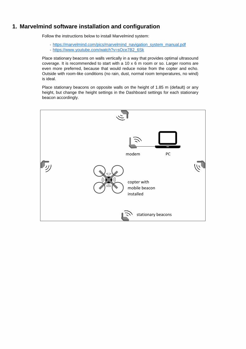
Place stationary beacons on walls vertically in a way that provides optimal ultrasound
coverage. It is recommended to start with a 10 x 6 m room or so. Larger rooms are
even more preferred, because that would reduce noise from the copter and echo.
Outside with room-like conditions (no rain, dust, normal room temperatures, no wind)
is ideal.
Place stationary beacons on opposite walls on the height of 1.85 m (default) or any
height, but change the height settings in the Dashboard settings for each stationary
beacon accordingly.
modem PC
copter with
mobile beacon
installed
stationary beacons

• Connect modem to your PC
• Run the Dashboard
• On the map, the program should have beacons, as shown below in the
screenshot.
• Each beacon has its own address from 0 to 99, which can be reassigned. To
do this, go to the right Dashboard parameters panel and choose Device
address (0..99)
• Next, you need one of the beacons and assign a mobile "Hedgehog", to be
installed on the copter. For this purpose, we select one of the beacons in the
bottom panel and in the appeared list of parameters for it, in the line "Hedgehog
mode" we set "Enabled"
• After that, the selected beacon will turn blue (means, it becomes a mobile
beacon or “hedgehog”/”hedge”)

• To start with the system, click "Freeze map". Do it only, when the table of
distances (top-left corner) is white. Mobile beacon will start emitting at a certain
frequency set in the Ultrasonic Settings (default: 31kHz) ultrasonic pulses, and
the map will show its movement when the mobile beacon moves.

2. Autopilot setup
To configure the autopilot, download and install the Mission Planner software -
http://firmware.eu.ardupilot.org/Tools/MissionPlanner
Also, you need to download special software and settings for autopilot:
Autopilot software:
https://drive.google.com/file/d/0B7tPlrvOUY3xb3ktM1gyRG1mTEk/view?usp=sharing
Parameter file:
https://drive.google.com/open?id=1divK2S-GHWtCpam-9vlf5DdFkmVqQbo5
3. Setting up PixHawk
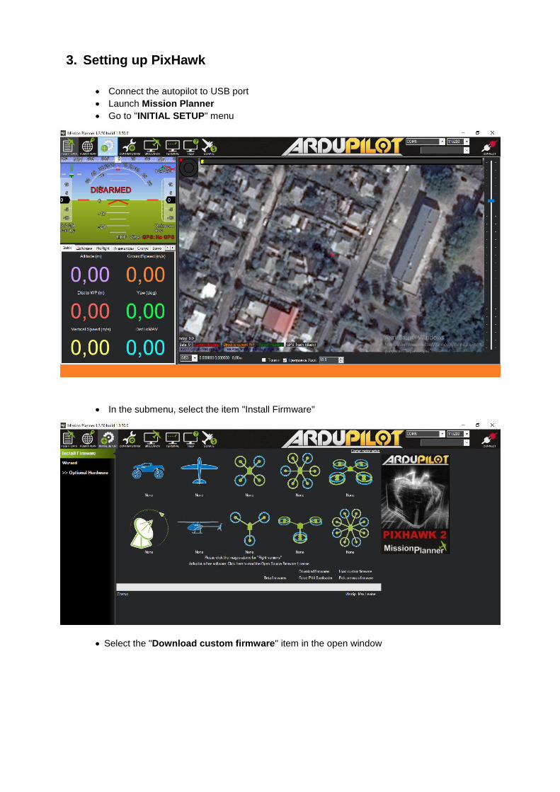
• Connect the autopilot to USB port
• Launch Mission Planner
• Go to "INITIAL SETUP" menu
• In the submenu, select the item "Install Firmware"
• Select the "Download custom firmware" item in the open window

• Find an unpacked file named "ArduCopter-v2.px4" and click open"
• Wait until the software is downloaded to the autopilot; autopilot will be
signaling in the end of the download
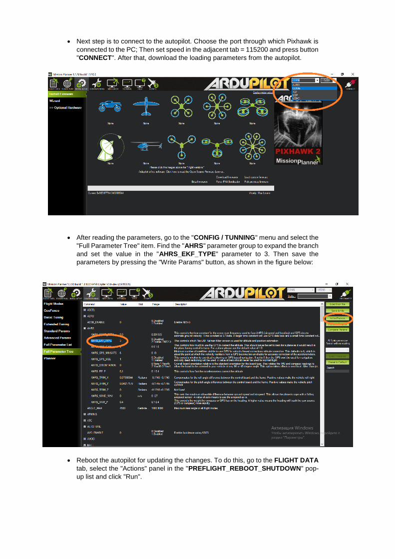
• Next step is to connect to the autopilot. Choose the port through which Pixhawk is
connected to the PC; Then set speed in the adjacent tab = 115200 and press button
"CONNECT". After that, download the loading parameters from the autopilot.
• After reading the parameters, go to the "CONFIG / TUNNING" menu and select the
"Full Parameter Tree" item. Find the "AHRS" parameter group to expand the branch
and set the value in the "AHRS_EKF_TYPE" parameter to 3. Then save the
parameters by pressing the "Write Params" button, as shown in the figure below:
• Reboot the autopilot for updating the changes. To do this, go to the FLIGHT DATA
tab, select the "Actions" panel in the "PREFLIGHT_REBOOT_SHUTDOWN" pop-
up list and click "Run".

• After reboot, connect to the autopilot again and read the parameters. Then go to
the "CONFIG / TUNNING" menu and select the "Full Parameter Tree" item. On the
right, we click the button "Download from file". Pixelfok.ru, select it and click the
"Open" button.

• In the appeared message we press the button "Ok". After that, all the parameters
that have been changed are highlighted in green. To record them in the autopilot,
press the "Write Params" button, then restart the autopilot.
• Connect the autopilot again to the PC, connect, read the parameters. We now turn
to setting the frame type of the copter. To do this, select the "INITIAL SETUP"
menu, then select "Frame Type" in the "Mandatory Hardware" submenu. We
choose the frame type for our copter, for example, the X-shaped quadcopter

• Next, configure the accelerometers, for which we move on to the next item "Accel
Calibration". Locate the copter immovably and strictly in the horizon (This will
further determine the stability in flight) and do not move copter during the calibration
at the level of the horizon. Press the lower button "Calibrate Level".
During calibration, the main LED on the autopilot will flash red and blue alternately, after
the completion, button sign will change to "Completed", which means that the
calibration is completed by level.
Next step is to calibrate the accelerometers along the axes of the copter. Place the
copter in front of you, copter nose directed from you. Press the top button "Calibrate
Accel" and the program will ask you to place the copter in the horizon. Place it
motionless in the horizon and press any key on the keyboard, then the program will ask
you to place the copter on all axes motionlessly as shown in the figure and each time
confirm the location on a certain axis by pressing any key
After successful calibration, "Calibration Successful" sign will appear
A good example of calibration: https://vimeo.com/56224615
It is important the copter stay immovable after pressing the key for each step.
The position of the horizon level is the most important factor to obtain the
correct offset factor, which your controller relies during the flight upon.
4. Compass calibration
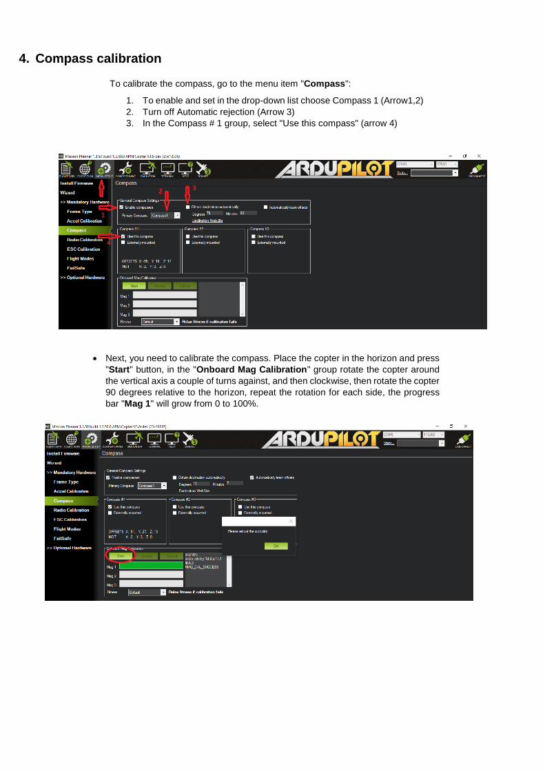
To calibrate the compass, go to the menu item "Compass":
1. To enable and set in the drop-down list choose Compass 1 (Arrow1,2)
2. Turn off Automatic rejection (Arrow 3)
3. In the Compass # 1 group, select "Use this compass" (arrow 4)
• Next, you need to calibrate the compass. Place the copter in the horizon and press
"Start" button, in the "Onboard Mag Calibration" group rotate the copter around
the vertical axis a couple of turns against, and then clockwise, then rotate the copter
90 degrees relative to the horizon, repeat the rotation for each side, the progress
bar "Mag 1" will grow from 0 to 100%.
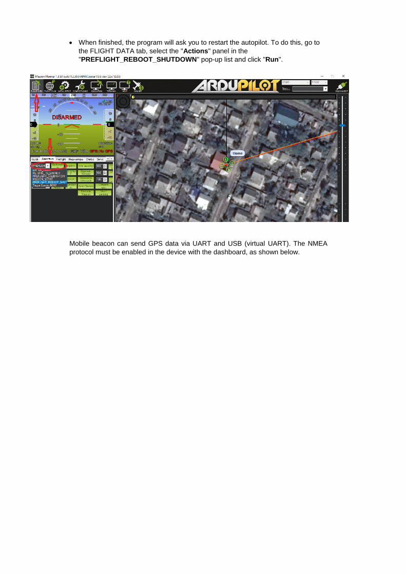
• When finished, the program will ask you to restart the autopilot. To do this, go to
the FLIGHT DATA tab, select the "Actions" panel in the
"PREFLIGHT_REBOOT_SHUTDOWN" pop-up list and click "Run".
Mobile beacon can send GPS data via UART and USB (virtual UART). The NMEA
protocol must be enabled in the device with the dashboard, as shown below.
5. Setting up the equipment
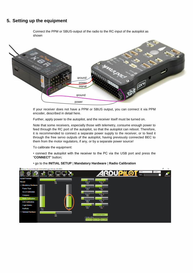
Connect the PPM or SBUS-output of the radio to the RC-input of the autopilot as
shown
If your receiver does not have a PPM or SBUS output, you can connect it via PPM
encoder, described in detail here.
Further, apply power to the autopilot, and the receiver itself must be turned on.
Note that some receivers, especially those with telemetry, consume enough power to
feed through the RC port of the autopilot, so that the autopilot can reboot. Therefore,
it is recommended to connect a separate power supply to the receiver, or to feed it
through the free servo outputs of the autopilot, having previously connected BEC to
them from the motor regulators, if any, or by a separate power source!
To calibrate the equipment:
• connect the autopilot with the receiver to the PC via the USB port and press the
"CONNECT" button;
• go to the INITIAL SETUP | Mandatory Hardware | Radio Calibration
ground
ground
power signal
power
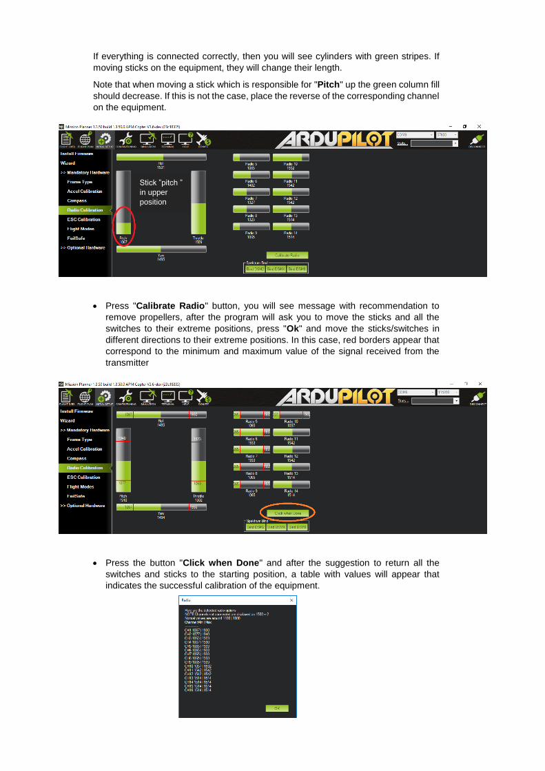
If everything is connected correctly, then you will see cylinders with green stripes. If
moving sticks on the equipment, they will change their length.
Note that when moving a stick which is responsible for "Pitch" up the green column fill
should decrease. If this is not the case, place the reverse of the corresponding channel
on the equipment.
• Press "Calibrate Radio" button, you will see message with recommendation to
remove propellers, after the program will ask you to move the sticks and all the
switches to their extreme positions, press "Ok" and move the sticks/switches in
different directions to their extreme positions. In this case, red borders appear that
correspond to the minimum and maximum value of the signal received from the
transmitter
• Press the button "Click when Done" and after the suggestion to return all the
switches and sticks to the starting position, a table with values will appear that
indicates the successful calibration of the equipment.
Stick ”pitch ”
in upper
position

6. Calibration of the speed regulators
To calibrate the regulators:
• Remove the propellers and connect the battery to the copter;
• Connect the copter to the PC via the USB port and press the "CONNECT" button;
• Then go to the INITIAL SETUP | Mandatory Hardware | ESC Calibration
• Press the "Calibrate ESC" button
• Disconnect the USB cable and battery
• Connect the battery
• After that, you will hear first the sounds that are typical for the calibration of your
controllers, after which the signal for the normal start of the regulators will sound.
• Disconnect the battery.

7. Flight mode setting
Remove the propellers and connect the battery to the copter;
• Set the 3-position control switch to channel 5
• Connect the copter to the PC via the USB port and press the "CONNECT" button;
Then go to the INITIAL SETUP | Mandatory Hardware | Flight Modes
When switching the three-position switch, various flight modes will be highlighted in
green. Select your flight mode for each switch position. For example, for:
• In the upper position, set "Stabilize" (the flight is in fully manual mode), the copter
ignores the navigation system and only holds the horizon.
• Middle position "PosHold" (when releasing the stick "Pich-Roll", the stick of gas
in the middle of the copter hangs in place, at a certain height, relying on data from
the Marvelmind navigation system)
•
• The lower position "Auto" gives the command to execute the flight task (flying by
points).
•
• Click the "Save Modes" button
8. Preparing copter for flight
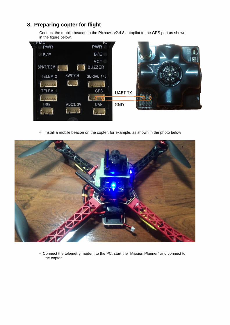
Connect the mobile beacon to the Pixhawk v2.4.8 autopilot to the GPS port as shown in the figure below.
• Install a mobile beacon on the copter, for example, as shown in the photo below
• Connect the telemetry modem to the PC, start the "Mission Planner" and connect to the copter

• Connect the "Marvelmind" modem to the PC, start "Dashboard", and press the "Freeze map" button
• Install the copter in its original position, from which it must take off
• Next, go to the FLIGHT DATA page
• On the bottom panel in the "Quick" tab, find the parameter "Yaw (deg)"
• Subtract the displayed number from 360.
This will be the correction for the magnetic north of the position of the Copter. It must be entered in the compass settings.
To do this, go to the page INITIAL SETUP | Mandatory Hardware | Compass and make this correction in the panel "General Compass Settings"
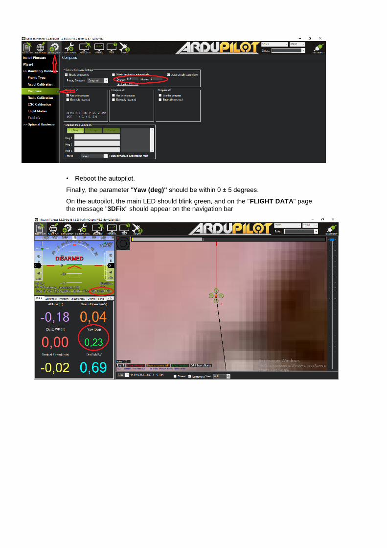
• Reboot the autopilot.
Finally, the parameter "Yaw (deg)" should be within 0 ± 5 degrees.
On the autopilot, the main LED should blink green, and on the "FLIGHT DATA" page the message "3DFix" should appear on the navigation bar

9. Dashboard setting up
• Connect the Marvelmind modem, as well as the autopilot telemetry modem to the PC
• To exclude mutual radio interference of equipment, you may try to use different frequency bands, for example, 915 MHz for autopilot modems and 433 MHz for the Marvelmind modem. In case it is not possible, try to use farther frequency channels and separate antennas
• Launch "Dashboard" and "Mission Planner"
• Arrange the copter in its original state, from which it must take off
• Connect the battery to the Copter and wait for it to complete initialization
• Select the virtual Com port to which the autopilot telemetry modem is connected, set the speed to 57600 baud and press "CONNECT"
• In "Mission Planner", the parameter "Yaw (deg)" should be between 356 and 5 degrees, but the closer to 0 is better
• In the "Dashboard" select the modem and in the right pane, in the properties you need to specify the coordinates of the place where the copter will fly

• To do so, visit https://www.google.com/maps/, for example. Find the place of flights on the map, click on it, information about this place includes coordinates of this place.
• Add these coordinates to the properties of "Georeferencing"

• Choose the "hedgehog" in the lower device panel
• Next, in the "Interfaces" parameter, set the UART speed to 115200 baudrate, and the "NMEA"
• Next, select one of the beacons on the bottom panel and set the "Number of periods" parameter to 50, press "Ctrl" on the keyboard and press "Write all"
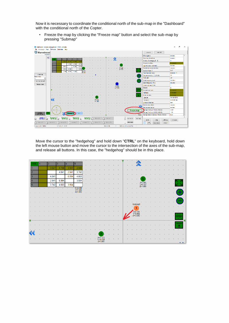
Now it is necessary to coordinate the conditional north of the sub-map in the "Dashboard" with the conditional north of the Copter.
• Freeze the map by clicking the "Freeze map" button and select the sub-map by pressing "Submap"
Move the cursor to the "hedgehog" and hold down "CTRL" on the keyboard, hold down the left mouse button and move the cursor to the intersection of the axes of the sub-map, and release all buttons. In this case, the "hedgehog" should be in this place.
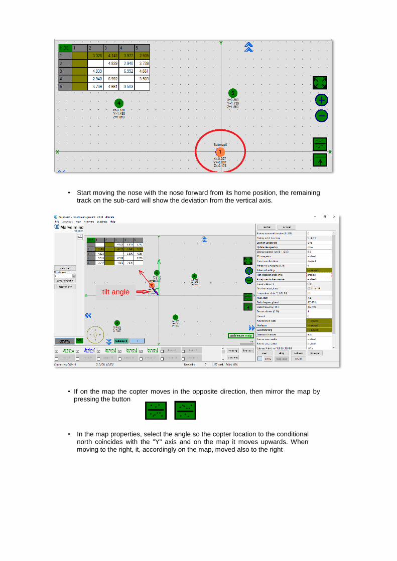
• Start moving the nose with the nose forward from its home position, the remaining track on the sub-card will show the deviation from the vertical axis.
• If on the map the copter moves in the opposite direction, then mirror the map by pressing the button
• In the map properties, select the angle so the copter location to the conditional north coincides with the "Y" axis and on the map it moves upwards. When moving to the right, it, accordingly on the map, moved also to the right
tilt angle
10. Building a route with “Mission Planner”
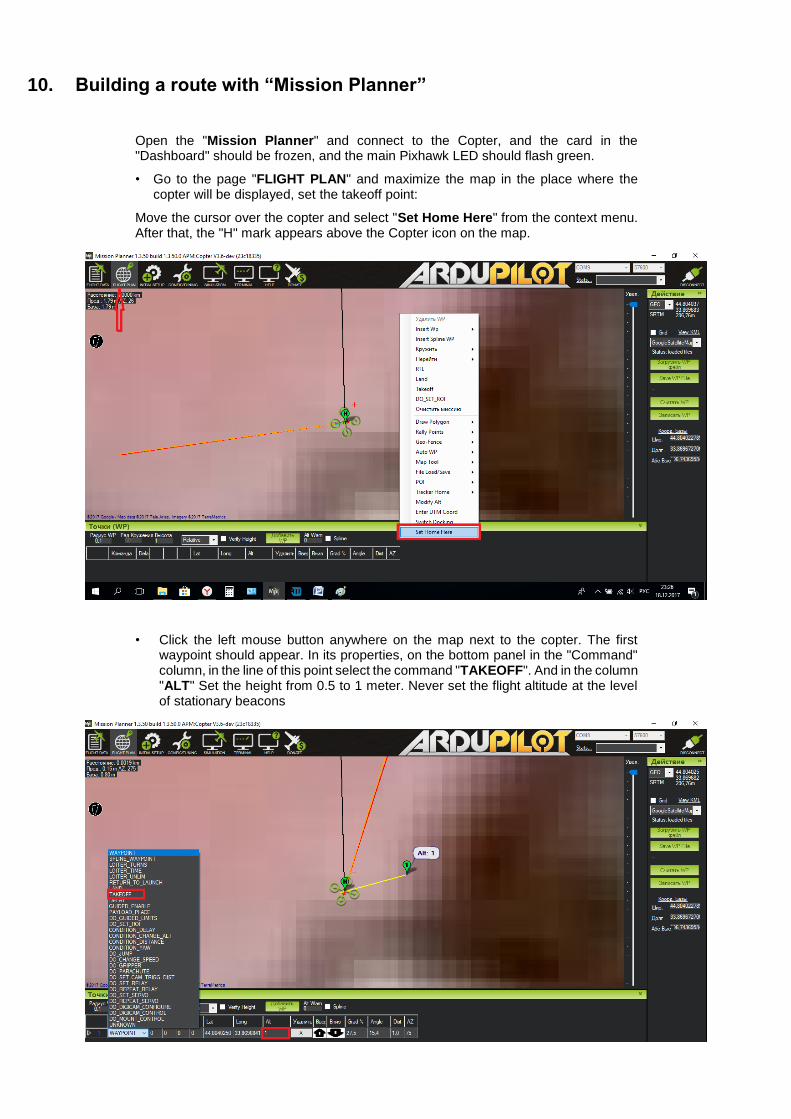
Open the "Mission Planner" and connect to the Copter, and the card in the "Dashboard" should be frozen, and the main Pixhawk LED should flash green.
• Go to the page "FLIGHT PLAN" and maximize the map in the place where the copter will be displayed, set the takeoff point:
Move the cursor over the copter and select "Set Home Here" from the context menu. After that, the "H" mark appears above the Copter icon on the map.
• Click the left mouse button anywhere on the map next to the copter. The first waypoint should appear. In its properties, on the bottom panel in the "Command" column, in the line of this point select the command "TAKEOFF". And in the column "ALT" Set the height from 0.5 to 1 meter. Never set the flight altitude at the level of stationary beacons

• Further, without turning the copter on the "Yaw", move the copter physically to the next point of the route, on the map the copter will move to this point. Click the left button on the map where the copter is located, set the height leaving the point as "WAYPOINT" and so on.
• After building a route, move the copter to its original position, so that it is in the center of the "Dashboard" map and at the "H" point of the "Mission Planner" map. Then click the "Write WP" button.
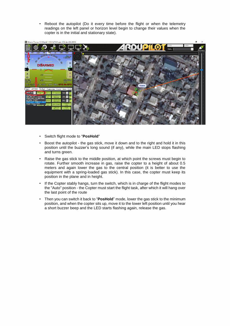
• Reboot the autopilot (Do it every time before the flight or when the telemetry readings on the left panel or horizon level begin to change their values when the copter is in the initial and stationary state).
• Switch flight mode to "PosHold"
• Boost the autopilot - the gas stick, move it down and to the right and hold it in this position until the buzzer’s long sound (if any), while the main LED stops flashing and turns green.
• Raise the gas stick to the middle position, at which point the screws must begin to rotate. Further smooth increase in gas, raise the copter to a height of about 0.5 meters and again lower the gas to the central position (it is better to use the equipment with a spring-loaded gas stick). In this case, the copter must keep its position in the plane and in height.
• If the Copter stably hangs, turn the switch, which is in charge of the flight modes to the "Auto" position - the Copter must start the flight task, after which it will hang over the last point of the route
• Then you can switch it back to “PosHold” mode, lower the gas stick to the minimum position, and when the copter sits up, move it to the lower left position until you hear a short buzzer beep and the LED starts flashing again, release the gas.

11. Contacts
For additional support, please send your questions to [email protected]
Please, also check this forum for more information. Here we will answer the most
common questions