Embed Size (px)
Citation preview
OPEN
ORIGINAL ARTICLE
Pixel super-resolution using wavelength scanning
Wei Luo1,2,3, Yibo Zhang1,2,3, Alborz Feizi1,2,3, Zoltan Gorocs1,2,3 and Aydogan Ozcan1,2,3,4
Undersampling and pixelation affect a number of imaging systems, limiting the resolution of the acquired images, which
becomes particularly significant for wide-field microscopy applications. Various super-resolution techniques have been imple-
mented to mitigate this resolution loss by utilizing sub-pixel displacements in the imaging system, achieved, for example, by
shifting the illumination source, the sensor array and/or the sample, followed by digital synthesis of a smaller effective pixel by
merging these sub-pixel-shifted low-resolution images. Herein, we introduce a new pixel super-resolution method that is based
on wavelength scanning and demonstrate that as an alternative to physical shifting/displacements, wavelength diversity can be
used to boost the resolution of a wide-field imaging system and significantly increase its space-bandwidth product. We confirmed
the effectiveness of this new technique by improving the resolution of lens-free as well as lens-based microscopy systems and
developed an iterative algorithm to generate high-resolution reconstructions of a specimen using undersampled diffraction pat-
terns recorded at a few wavelengths covering a narrow spectrum (10–30 nm). When combined with a synthetic-aperture-based
diffraction imaging technique, this wavelength-scanning super-resolution approach can achieve a half-pitch resolution of
250 nm, corresponding to a numerical aperture of ~ 1.0, across a large field of view (420 mm2). We also demonstrated the
effectiveness of this approach by imaging various biological samples, including blood and Papanicolaou smears. Compared with
displacement-based super-resolution techniques, wavelength scanning brings uniform resolution improvement in all directions
across a sensor array and requires significantly fewer measurements. This technique would broadly benefit wide-field imaging
applications that demand larger space-bandwidth products.
Light: Science & Applications (2016) 5, e16060; doi:10.1038/lsa.2016.60; published online 8 April 2016
Keywords: holographic imaging; on-chip microscopy; pixel super-resolution; wavelength scanning; wide-field imaging
INTRODUCTION
High-resolution imaging across a wide field of view (FOV) is essentialfor various applications in different fields and requires imagingsystems to have large space-bandwidth products. Ever since thewidespread adoption of CCDs (charge-coupled devices) and comple-mentary metal-oxide semiconductor (CMOS)-based image sensors tocapture digital images, a tremendous amount of research anddevelopment effort has been devoted to optics, semiconductortechnologies and signal processing to create high-resolution andwide-field imaging and microscopy systems. In conventional lens-based optical imaging designs, a large space-bandwidth product can beachieved by using higher magnification and larger lenses, and theimage sensors are accordingly made larger in area with higher pixelcounts. Another approach is to make image sensors with a smallerpixel pitch while still maintaining a relatively large active area.However, both of these approaches have drawbacks: Larger opticalcomponents make the imaging system bulky and significantly moreexpensive; in contrast, physically reducing the pixel size sacrificesthe signal-to-noise ratio because a smaller light sensing area is made
available for each pixel, reducing the external quantum efficiency ofthe imager chip1.As an alternative, the optical signal processing community has
provided a powerful framework, termed pixel super-resolution2–6, toobtain a high-resolution image from a series of low-resolution (that is,undersampled) images. Pixel super-resolution was originally developedin lens-based, point-to-point projection imaging systems2–6 and waslater applied to lens-free and holographic imaging techniques7–12 tosignificantly enhance the space-bandwidth product of the recon-structed images using both CCD and CMOS imager chips. In eitherimplementation, lens-based or lens-free, this super-resolution frame-work requires low-resolution undersampled measurements to havesub-pixel shifts with respect to each other so that new andindependent information can be exploited at each raw measurement(even though pixelated) to digitally synthesize a much smaller effectivepixel size for the reconstructed image.Herein, we introduce a fundamentally new pixel super-resolution
method that utilizes wavelength scanning to significantly improve theresolution of an undersampled or pixelated imaging system, without
1Electrical Engineering Department, University of California, Los Angeles, CA 90095, USA; 2Bioengineering Department, University of California, Los Angeles, CA 90095, USA;3California NanoSystems Institute (CNSI), University of California, Los Angeles, CA 90095, USA and 4Department of Surgery, David Geffen School of Medicine, University ofCalifornia, Los Angeles, CA 90095, USACorrespondence: A Ozcan, Email: [email protected] 29 September 2015; revised 9 December 2015; accepted 11 December 2015; accepted article preview online 14 December 2015
Light: Science & Applications (2016) 5, e16060; doi:10.1038/lsa.2016.60& 2016 CIOMP. All rights reserved 2047-7538/16www.nature.com/lsa
the use of any lateral shifts or displacements. In this technique, thespecimen is sequentially illuminated at a few wavelengths that aresampled from a rather narrow spectral range of 10–30 nm. Comparedwith sub-pixel displacement or lateral shift-based super-resolutiontechniques, wavelength scanning introduces a uniform resolutionimprovement across all the directions on the sample plane andrequires significantly fewer raw measurements to be made. Makingfewer measurements without sacrificing performance could greatlybenefit high-speed wide-field imaging, field-portable microscopy andtelemedicine applications, which are all sensitive to data transmissionand storage.We demonstrated the effectiveness of this new wavelength-
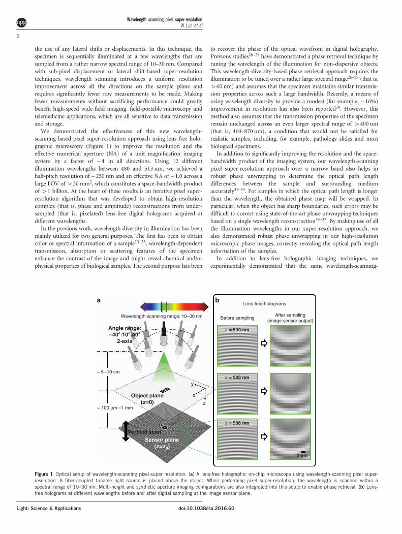
scanning-based pixel super-resolution approach using lens-free holo-graphic microscopy (Figure 1) to improve the resolution and theeffective numerical aperture (NA) of a unit magnification imagingsystem by a factor of ~ 4 in all directions. Using 12 differentillumination wavelengths between 480 and 513 nm, we achieved ahalf-pitch resolution of ~ 250 nm and an effective NA of ~ 1.0 across alarge FOV of420 mm2, which constitutes a space-bandwidth productof 41 billion. At the heart of these results is an iterative pixel super-resolution algorithm that was developed to obtain high-resolutioncomplex (that is, phase and amplitude) reconstructions from under-sampled (that is, pixelated) lens-free digital holograms acquired atdifferent wavelengths.In the previous work, wavelength diversity in illumination has been
mainly utilized for two general purposes. The first has been to obtaincolor or spectral information of a sample13–25; wavelength-dependenttransmission, absorption or scattering features of the specimenenhance the contrast of the image and might reveal chemical and/orphysical properties of biological samples. The second purpose has been
to recover the phase of the optical wavefront in digital holography.Previous studies26–29 have demonstrated a phase retrieval technique bytuning the wavelength of the illumination for non-dispersive objects.This wavelength-diversity-based phase retrieval approach requires theillumination to be tuned over a rather large spectral range26–29 (that is,460 nm) and assumes that the specimen maintains similar transmis-sion properties across such a large bandwidth. Recently, a means ofusing wavelength diversity to provide a modest (for example, ~ 16%)improvement in resolution has also been reported30. However, thismethod also assumes that the transmission properties of the specimenremain unchanged across an even larger spectral range of 4400 nm(that is, 460–870 nm), a condition that would not be satisfied forrealistic samples, including, for example, pathology slides and mostbiological specimens.In addition to significantly improving the resolution and the space-
bandwidth product of the imaging system, our wavelength-scanningpixel super-resolution approach over a narrow band also helps inrobust phase unwrapping to determine the optical path lengthdifferences between the sample and surrounding mediumaccurately31–33. For samples in which the optical path length is longerthan the wavelength, the obtained phase map will be wrapped. Inparticular, when the object has sharp boundaries, such errors may bedifficult to correct using state-of-the-art phase unwrapping techniquesbased on a single wavelength reconstruction34–37. By making use of allthe illumination wavelengths in our super-resolution approach, wealso demonstrated robust phase unwrapping in our high-resolutionmicroscopic phase images, correctly revealing the optical path lengthinformation of the samples.In addition to lens-free holographic imaging techniques, we
experimentally demonstrated that the same wavelength-scanning-
Wavelength scanning range: 10–30 nm
Angle range:–40°:10°:40°
2-axis
Object plane(z=0)
y
Sensor plane(z=z0)
Vertical scan
~ 5–10 cm
~ 100 μm –1 mm
Lens-free holograms
Before samplingAfter sampling
(image sensor output)
a b
x
z
2 �m
� = 536 nm
� = 533 nm
� = 530 nm
Figure 1 Optical setup of wavelength-scanning pixel-super resolution. (a) A lens-free holographic on-chip microscope using wavelength-scanning pixel super-resolution. A fiber-coupled tunable light source is placed above the object. When performing pixel super-resolution, the wavelength is scanned within aspectral range of 10–30 nm. Multi-height and synthetic aperture imaging configurations are also integrated into this setup to enable phase retrieval. (b) Lens-free holograms at different wavelengths before and after digital sampling at the image sensor plane.
Wavelength scanning pixel super-resolutionW Luo et al
2
Light: Science & Applications doi:10.1038/lsa.2016.60
based super-resolution framework can also be applied to improve theresolution of lens-based imaging systems with the introduction of aslight defocus, making this work broadly applicable to variouscoherent or partially coherent wide-field imaging modalities that arelimited by pixelation or undersampling. Therefore, we believe that thisnew wavelength-scanning-based super-resolution technique wouldlargely benefit wide-field and high-throughput microscopy applica-tions that require enhanced space-bandwidth products.
MATERIALS AND METHODS
Optical setupAs depicted in Figure 1, the optical setup of the lens-free microscopeconsists of three major components: a light source, an image sensorarray, and a specimen. A fiber-coupled, wavelength-tunable lightsource (WhiteLase-Micro, model VIS, Fianium Ltd, Southampton,UK) is used to perform the wavelength scanning. During the imagingprocess, the central wavelength of the source is scanned within aspectral range of 10–30 nm (for example, from 498 to 510 nm) with astep size of ~ 3 nm. The spectral linewidth of illumination at eachwavelength is ~ 2 nm, and the power of the light source is adjusted to~20 μW. The image sensor chip is a color CMOS sensor chip with apixel size of 1.12 μm manufactured for cellphone camera modules(IU081, Sony Corporation, Tokyo, Japan). During the imaging process,the specimen is mounted on a transparent substrate and placed 100–500 μm above the image sensor chip. We merged our wavelength-scanning-based pixel super-resolution approach with both multi-height11 and synthetic aperture imaging12 configurations to obtainphase-retrieved, high-resolution reconstructions of the specimen. Forsynthetic-aperture-based imaging12, the fiber outlet of the light sourceis mounted on a rotational arm (PRM1Z8, Thorlabs, Newton, NJ,USA), and the image sensor is placed on a stage that can rotate over ahorizontal plane. Therefore, the incident light can be set to arbitraryillumination angles, which is required for the synthetic apertureapproach. For multi-height-based phase retrieval9,11, the incrementalheight change between the image sensor and the specimen is enabledby a mechanical positioning stage (MAX606, Thorlabs). The imagesensor is mounted on this mechanical stage, whereas the specimen isheld by a three-dimensional-printed sample holder. After completingimage capture for each height, the stage lowers the image sensor by 10–15 μm on average before the image capture for the next height starts.During the imaging process, all the necessary steps, including thewavelength scanning of the light source, multi-height and synthetic-aperture-related scans and data acquisition using the image sensor chipare automated by a custom-written LabVIEW code (Version 2011,National Instruments, Austin, TX, USA).
Wavelength calibration and dispersion compensationWavelength calibration of our light source is achieved using an opticalspectrum analyzer (HR2000+, Ocean Optics, Amersham, UK). Theintensity-weighted average wavelength of each measured spectrum isconsidered as our illumination wavelength. To achieve optimalresolution, the refractive index of the glass substrate (100 μm,N-BK7, Schott AG, Mainz, Germany) at each wavelength is alsocorrected using the dispersion formula for borosilicate glass.
Sample preparationThe grating lines used for resolution quantification are fabricated on a~ 100 μm glass slide (N-BK7, Schott AG) using focused ion beammilling. Unstained Papanicolaou (Pap) smear slides are preparedthrough the ThinPrep method (Hologic, Inc., Marlborough, MA,USA). The blood smear samples are prepared using EDTA
(ethylenediaminetetraacetic acid) anticoagulated human blood andstained with Wright’s stain38.
Mathematical formalism of wavelength-scanning pixelsuper-resolutionWe assume that the specimen is a thin object mounted on a planeparallel to the image sensor chip and that the specimen is sequentiallyilluminated by multiple wavelengths {λk}. At a given wavelength λk, theobject wave can be written as ok(x, y)= 1+sk(x, y), where sk(x, y)represents the scattered object wave, immediately at the exit of theobject plane (z= 0, in Figure 1a). The two-dimensional Fouriertransform of ok(x, y) can be written as Ok(fx, fy)= δ(fx, fy)+Sk(fx, fy).At the image sensor plane (z= z0 in Figure 1a), the Fourier transformof the intensity distribution, ik(x, y), can be written as (seeSupplementary Information for details):
Ik ¼ dþ Tk ? Sk þ T�k ? S�k
� �� þ SSk ð1Þ
To simplify our notation, we hide the expression of the variables forspatial frequencies (fx, fy), and the superscript ‘− ’ represents (− fx,− fy). On the right-hand side of Equation (1), the first item, δ,represents the background intensity; the second and third items areconjugate holographic terms, which represent the interference of thescattered object wave with the background wave at the sensor plane.The fourth item is the self-interference term, which can be considerednegligible for weakly scattering objects. The expression for Tk can bewritten as follows:
Tkðf x; f yÞ ¼ H�k f x;k; f y;k
� �?Hk f x þ f x;k; f y þ f y;k
� �ð2Þ
Where Hk(fx, fy) is the free space transfer function, and the frequencyshifts fx,k and fy,k are determined by the illumination wavelength andthe incident angle (refer to the Supplementary Information fordetails). After the object intensity is sampled by an image sensorarray with a pixel pitch of Δx and Δy, the discrete Fourier transformof the sensor’s output can be expressed as follows39:
Isampled; k ¼X
u; v¼0; 71;:::
Ipix; k f x �u
Dx; f y �
v
Dy
� �ð3Þ
where u and v are integers and fx and fy are discrete spatial frequencyvalues. Note that Ipix,k(fx, fy)= Ik(fx, fy)·Pk(fx, fy), where Pk(fx, fy)represents the Fourier transform of the pixel function, that is, thetwo-dimensional responsivity distribution40 within each pixel: pk(x, y).Variables u and v represent the order of spatial aliasing due topixelation, and (u, v)= (0,0) corresponds to the non-aliased real (thatis, target) signal. The periodic nature of the discrete Fourier transformenables us to extend the expression of Isampled, k to a broader frequencyspace by upsampling (Figure 2). Based on these definitions, we canexpress the undersampled or pixelated lens-free hologram at a givenwavelength λk as follows:
Isampled; k ¼Xu; v
duv þ Tuv; k ? Suv; k þ T�uv; k ? S
�uv; k
� ��þ SSuv; k
h i? Puv; k
ð4Þ
The non-aliased target signal ok(x, y) or its spatial Fourier spectrumcan be obtained under (u, v)= (0,0), that is, δ00+S00, k, which can be
Wavelength scanning pixel super-resolutionW Luo et al
3
Light: Science & Applicationsdoi:10.1038/lsa.2016.60
written as follows:
d00 þ S00; k� �
? P00; k ¼ T�00; k ? Isampled; k � T�
00; k ?T��00; k ? P00; k ? S
��00; k
�X
ua0; va0
T�00; k ?Tuv; k ? Puv; k ? Suv; k þ T�
00; k ?T��uv; k ? Puv; k ? S
��uv; k
� �
�X
ua0; va0
T�00; k ? duv �
Xu; v¼0;71;:::
T�00; k ? Puv; k ? SSuv; k
ð5ÞOn the left side of Equation (5), we retain the pixel function P00, k,which can be removed later in the last step of the image reconstruc-tion, using, for example, spatial deconvolution with a Wiener filter41, asillustrated in ref. 40. Equation (5) also shows that to obtain the non-aliased object at (u, v)= (0,0), one needs to eliminate or subtract fourterms from the upsampled and back-propagated holographic term (thatis, T�
00; k ? Isampled; k). To this end, the first item to eliminate,T�00; k ?T
��00; k ? P00; k ? S
��00; k, is the twin image noise, a characteristic
artifact of in-line holography. The second term in Equation (5), whichcontains Suv; k and S��
uv; k (ua0, va0) in the summation, represents theeffects of spatial aliasing and undersampling for both the real and twinimage terms. The third item, which contains duv in the summation, isthe periodic background artifact generated during the upsamplingprocess, and the last item is the self-interference term and itsupsampling related artifacts. Starting with the next sub-section, we willdiscuss a two-stage reconstruction algorithm for eliminating all four ofthese items listed on the right side of Equation (5) using wavelengthscanning to enable super-resolved reconstructions of complex (that is,phase and amplitude) object functions.
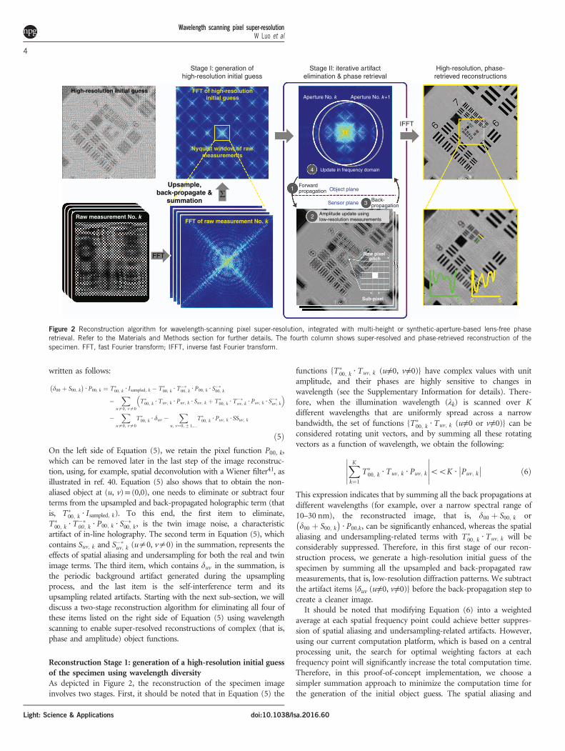
Reconstruction Stage 1: generation of a high-resolution initial guessof the specimen using wavelength diversityAs depicted in Figure 2, the reconstruction of the specimen imageinvolves two stages. First, it should be noted that in Equation (5) the
functions {T�00; k ?Tuv; k (u≠0, v≠0)} have complex values with unit
amplitude, and their phases are highly sensitive to changes inwavelength (see the Supplementary Information for details). There-fore, when the illumination wavelength (λk) is scanned over Kdifferent wavelengths that are uniformly spread across a narrowbandwidth, the set of functions {T�
00; k ?Tuv; k (u≠0 or v≠0)} can beconsidered rotating unit vectors, and by summing all these rotatingvectors as a function of wavelength, we obtain the following:
XKk¼1
T�00; k ?Tuv; k ? Puv; k
����������ooK ? Puv; k
�� �� ð6Þ
This expression indicates that by summing all the back propagations atdifferent wavelengths (for example, over a narrow spectral range of10–30 nm), the reconstructed image, that is, d00 þ S00; k ord00 þ S00; k� �
? P00;k, can be significantly enhanced, whereas the spatialaliasing and undersampling-related terms with T�
00; k ?Tuv; k will beconsiderably suppressed. Therefore, in this first stage of our recon-struction process, we generate a high-resolution initial guess of thespecimen by summing all the upsampled and back-propagated rawmeasurements, that is, low-resolution diffraction patterns. We subtractthe artifact items {δuv (u≠0, v≠0)} before the back-propagation step tocreate a cleaner image.It should be noted that modifying Equation (6) into a weighted
average at each spatial frequency point could achieve better suppres-sion of spatial aliasing and undersampling-related artifacts. However,using our current computation platform, which is based on a centralprocessing unit, the search for optimal weighting factors at eachfrequency point will significantly increase the total computation time.Therefore, in this proof-of-concept implementation, we choose asimpler summation approach to minimize the computation time forthe generation of the initial object guess. The spatial aliasing and
Stage I: generation ofhigh-resolution initial guess
Stage II: iterative artifactelimination & phase retrieval
High-resolution, phase-retrieved reconstructions
ForwardpropagationΣ
Back-propagation
IFFT
Object plane
Sensor plane
FFT of high-resolutioninitial guess
FFT of raw measurement No. kRaw measurement No. k
Aperture No. k Aperture No. k+1
4
1
3
2
Sub-pixel
Raw pixel pitch
Update in frequency domain
High-resolution initial guess
Upsample,back-propagate &
summation
FFT
Amplitude update usinglow-resolution measurements
Nyquist window of rawmeasurements
Figure 2 Reconstruction algorithm for wavelength-scanning pixel super-resolution, integrated with multi-height or synthetic-aperture-based lens-free phaseretrieval. Refer to the Materials and Methods section for further details. The fourth column shows super-resolved and phase-retrieved reconstruction of thespecimen. FFT, fast Fourier transform; IFFT, inverse fast Fourier transform.
Wavelength scanning pixel super-resolutionW Luo et al
4
Light: Science & Applications doi:10.1038/lsa.2016.60
undersampling-related artifacts of this initial guess will be furthereliminated and cleaned up during the second stage of our algorithm,as will be detailed next.
Reconstruction Stage 2: multi-wavelength-based iterative pixelsuper-resolution and phase retrievalThe second stage of our numerical reconstruction involves an iterativealgorithm, which contains four sub-steps in each iteration:(1) Knowing each raw measurement’s corresponding wavelength
and incidence angle, we apply the corresponding plane wave illumina-tion on the initial guess of the specimen (from Stage 1, discussedabove) and propagate the optical field from the object plane to theimage sensor plane using the angular spectrum approach42.(2) The amplitude of the high-resolution field on the image sensor
plane is updated using the low-resolution measurement at thecorresponding wavelength. To this end, the intensity of the high-resolution field is convolved with the image sensor’s pixel functionand downsampled to the same grid size as the pixelated rawmeasurement. The difference between the raw measurement and thedownsampled intensity map is considered a low-resolution ‘correc-tion’ map for each illumination wavelength. A high-resolutioncorrection map can then be generated by taking the Kroneckerproduct of this low-resolution map and the pixel function. To performa smooth update, this high-resolution correction map is added to thehigh-resolution intensity distribution with a relaxation parameter,typically set to ~0.5 (see the Supplementary Information for details).After the smoothed update, a Wiener deconvolution filter thatincorporates the image sensor’s noise level is applied to this updatedintensity distribution. The square root of this filtered high-resolutionintensity distribution is then applied to the amplitude of the field onthe sensor plane while the phase map is kept unaltered.(3) This updated field is then back-propagated to the object plane.(4) The back-propagated field is used to update the transmission
field on the object plane. This update is performed in the frequencydomain (Figure 2) within a circular area whose center is determinedby the corresponding illumination wavelength and angle. The radius ofthis circle is defined by the boundary within which all the spatialfrequencies experience an attenuation of less than 3 dB after propaga-tion in the spatial domain. This update on the object plane is alsosmoothed using a relaxation factor of ~ 0.5. After the update, thephase of the field on the object plane is converted to an optical pathlength map, and its amplitude is directly used as the transmission ofthe object.The four steps described above are performed for every raw (that is,
undersampled) measurement captured by the image sensor array. It isconsidered one iteration cycle when each one of the raw measure-ments has been used for amplitude update. Typically after 5–10iteration cycles, the reconstruction converges. The convergence con-dition for the iteration is defined as follows43:
SSEitravg � SSEitr�1avg
��� ���oε ð7Þwhere SSEitr
avg is the sum-squared error between the raw measurementand the downsampled intensity map43, ‘itr’ is the iteration number,and ε is a convergence constant determined by the noise level of theraw (that is, undersampled) measurements.
Phase retrieval using multi-height and synthetic aperturetechniquesMulti-height9,11,44–46 and synthetic aperture12 techniques have beenproven to be robust phase retrieval methods for lens-free on-chip
imaging. In previously reported lens-free reconstructions9,11,12, pixelsuper-resolution and phase retrieval are carried out sequentially: ateach height or illumination angle, lateral shift-based pixel super-resolution is first performed to obtain high-resolution diffractionpatterns on the image sensor plane. These super-resolved diffractionpatterns are then used by an iterative phase retrieval algorithm, inwhich wave propagations between the object plane and the imagesensor plane are executed repeatedly9,11,12. However, in wavelength-scanning-based pixel super-resolution, raw measurements are essen-tially undersampled versions of different holograms. Therefore, wechoose to use the same iterative algorithm detailed in the previoussub-section (that is, Reconstruction Stage 2) to realize resolutionenhancement and phase retrieval altogether. More specifically, in themulti-height configuration, the specimen is illuminated sequentially ateach wavelength, and the corresponding lens-free holograms arecaptured before the vertical scanning stage moves the sample or theimage sensor to the next height. Each height will be labeled with indexl; therefore, all the measurements {Isampled, k} and the correspondingtransfer functions {Hk} and {Tuv, k} that are used in the previousderivations can be relabeled as {Isampled, kl}, {Hkl} and{Tuv, kl}, respectively. During the numerical reconstruction process,all the raw holograms are upsampled, back-propagated, and thensummed together to generate the high-resolution initial guess at agiven height. In Stage 2 of our reconstruction algorithm, theaforementioned four-step process is applied to each raw measurement.The same set of operations and processing also apply to the syntheticaperture technique12, except that index l now refers to each illumina-tion angle instead of sample height.In general, for pathology slides such as blood smears and Pap
smears, the optical path length difference between the specimen (thatis, biological tissue) and the medium (that is, air or the sealing glue) israther small. Under these circumstances, phase unwrapping is not aconcern; therefore, in the phase recovery process, we can use ascrambled order of {Isampled, kl} in each iteration cycle. However, whenworking with samples with larger optical path length differences, suchas grating lines carved into a glass substrate, one extra step, that is,phase unwrapping, must be added after the reconstruction, and theorder of iterations must be modified accordingly, which will bedetailed in the next sub-section.
Multi-wavelength phase unwrappingA robust phase unwrapping algorithm requires high-resolution andphase-retrieved reconstructions at multiple wavelengths; therefore, wedivide the raw measurements into subsets, in which the wavelengthsare identical or very similar (for example, Δλ≤ 5 nm), and performthe four-step reconstruction process previously discussed (as part ofthe Reconstruction Stage 2) on each subset separately. For example,reconstruction number 1 uses subset {Isampled, kl | k= 1, l= 1,…L}, No.2 uses {Isampled, kl | k= 2, l= 1,…L} and so on. When the iterations forall these subsets are completed, we obtain high-resolution (that is,super-resolved) phase-retrieved reconstructions at multiple wave-lengths, that is, {Ok}, whose phase maps {ϕk,wrapped} need unwrapping.Using these wrapped phase maps {ϕk,wrapped} at multiple wavelengths,we perform phase unwrapping to accurately reveal the optical pathlength differences between the specimen and the surroundingmedium. Assuming that the optical path length difference is ΔL(x,y), the phase distribution at the object plane at each wavelength can bewritten as ϕk(x, y)= 2π·ΔL(x, y)/λk. The wrapped phase can thus beexpressed as ϕk,wrapped (x, y)=ϕk(x, y)± 2Nπ, where − πoϕk,wrapped≤π and N is an integer. These resulting wrapped phase maps {ϕk,
wrapped} that are generated through super-resolved and phase-retrieved
Wavelength scanning pixel super-resolutionW Luo et al
5
Light: Science & Applicationsdoi:10.1038/lsa.2016.60
reconstructions at multiple wavelengths are then fed into an optimiza-tion algorithm47 that finds the optimum path length ΔLopt(x,y) at eachspatial point (x,y) by minimizing a cost function defined as follows:
XKk¼1
ejfkðx; yÞ�ej2p ?DLoptðx; yÞ=lk�� ��2 ð8Þ
To avoid convergence to a local minimum and reduce the computa-tion cost/time, we define a search range of [ΔL0−min{λk}/2, ΔL0+min{λk}/2], where ΔL0 is the initial guess of the optical path length:
DL0ðx; yÞ ¼ 1
2p ? ðK � 1ÞXKk¼2
fkðx; yÞ � fk�1ðx; yÞ½ � ? lklk�1
lk�1 � lk
ð9Þwhere the total number of wavelengths (K) is typically 5–10. Withinthis search interval, we scan the values to find the optical path lengthΔLopt(x, y) that minimizes the cost function, resulting in anunwrapped object phase image.
Computation platform used for super-resolved imagereconstructionsOur reconstructions are performed using MATLAB (Version R2012a,MathWorks, Natick, MA, USA) on a desktop computer equipped witha 3.60-GHz central processing unit (Intel Xeon E5-1620) and 16 GB ofrandom-access memory. For a 1× 1 mm2 sub-region with an upsam-pling factor of seven, one iteration of our wavelength-scanning super-resolution routine takes ~ 1.2 s. For example, one cycle of ouralgorithm, which undergoes all the undersampled measurements(for example, seven wavelengths for each angle/height, and 22angles/heights in total), takes ~ 3 min. In our proof-of-conceptimplementation, the iterations did not use either GPU (graphicsprocessing unit) or parallel computing, which could significantlyimprove our overall computation time10. The total image reconstruc-tion time could be further improved by implementing the algorithmin the C language rather than MATLAB.
RESULTS AND DISCUSSION
The physical basis for wavelength-scanning pixel super-resolution isthe strong wavelength dependence of the undersampled interference
Wavelength scanningpixel super-resolution
Lateral shift-based pixel super-resolution
5 shifted images at each heightTotal 5 heights
9 shifted images at each heightTotal 5 heights
5 wavelengths used at each heightTotal 5 heights
Smallest resolved half-pitch: 0.62 �m
3 �m3 �m0 0 3 �m3 �m0 0 3 �m3 �m0 0
Smallest resolved half-pitch: 0.55 �m Smallest resolved half-pitch: 0.55 �m
a b c
Height: 330 μm:10 μm:370 μm Height: 330 μm:10 μm:370 μm Height: 330 μm:10 μm:370 μmλ = 510 nm λ = 510 nm λ = 498 nm: 3 nm: 510 nm
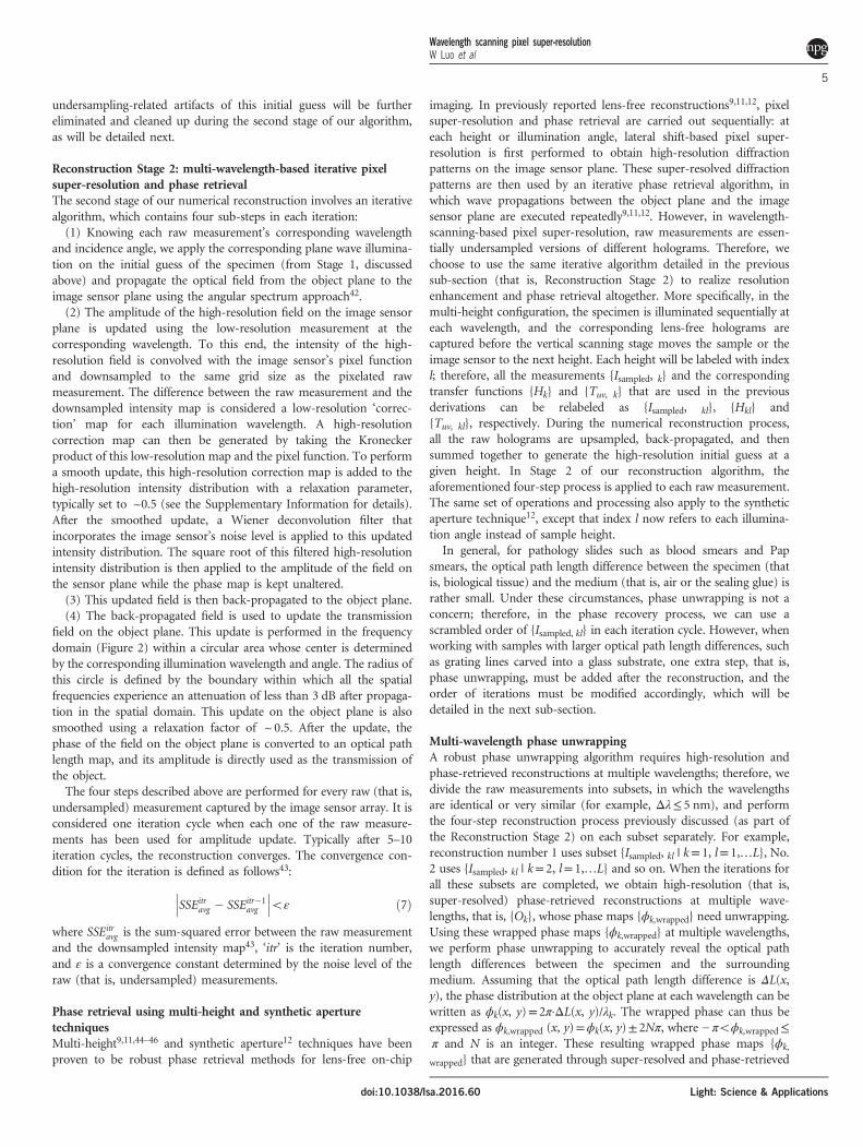
Figure 4 Lens-free imaging using multi-height phase retrieval and wavelength-scanning pixel super-resolution. Five heights are used in each case shown ina–c. (a, b) are lens-free reconstructions using lateral shift-based pixel super-resolution and multi-height phase retrieval. a uses five and b uses ninesub-pixel-shifted raw measurements at each height. (c) Lens-free reconstruction using wavelength-scanning pixel super-resolution and multi-height phaseretrieval; five wavelengths are used with a scanning range of 498–510 nm and a scan step size of 3 nm.
Reconstruction from singlemeasurement (z = 320 μm)
a b c d
Wavelength scanningpixel super-resolution (z = 320 μm)
Lateral shift-based pixel super-resolution (z = 320 μm)
Single measurement at 510 nm 5 shifted measurements 9 shifted measurements 5 wavelength measurements(498 nm : 3 nm :510 nm)Smallest resolved half-pitch: 0.98 �m
Smallest resolved half-pitch: 0.62 �mHologramshift table
Hologramshift table
sensorpixel
sensorpixel
Smallest resolvedhalf-pitch: 0.69 �m
Smallest resolvedhalf-pitch: 0.62 �m
4 �m04 �m04 �m04 �m04.5 �m05 �m06.5 �m07 �m0
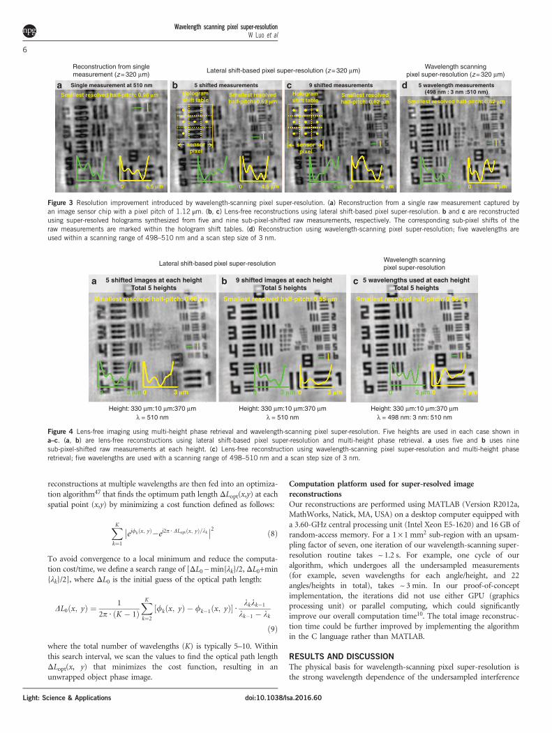
Figure 3 Resolution improvement introduced by wavelength-scanning pixel super-resolution. (a) Reconstruction from a single raw measurement captured byan image sensor chip with a pixel pitch of 1.12 μm. (b, c) Lens-free reconstructions using lateral shift-based pixel super-resolution. b and c are reconstructedusing super-resolved holograms synthesized from five and nine sub-pixel-shifted raw measurements, respectively. The corresponding sub-pixel shifts of theraw measurements are marked within the hologram shift tables. (d) Reconstruction using wavelength-scanning pixel super-resolution; five wavelengths areused within a scanning range of 498–510 nm and a scan step size of 3 nm.
Wavelength scanning pixel super-resolutionW Luo et al
6
Light: Science & Applications doi:10.1038/lsa.2016.60
patterns in coherent or partially coherent diffraction imaging systemssuch as lens-free, holographic microscopy (Figure 1) or defocusedlens-based imaging systems. When illuminated at slightly differentwavelengths, the high-frequency interference fringes caused by objectscattering will change, causing the undersampled output of the imagesensor chip to change as well (Figure 1b). Our derivations (Materialsand Methods section) show that in the spatial frequency domain, thealiasing signal caused by pixel-induced undersampling is modulated bya complex transfer function whose phase is rather sensitive to evensmall wavelength changes, which makes it possible to use wavelengthdiversity within a narrow spectral range (that is, 10–30 nm) to cancelout the spatial aliasing term and enhance the resolution of thereconstructions beyond the pixel pitch.This spatial resolution improvement brought by our wavelength-
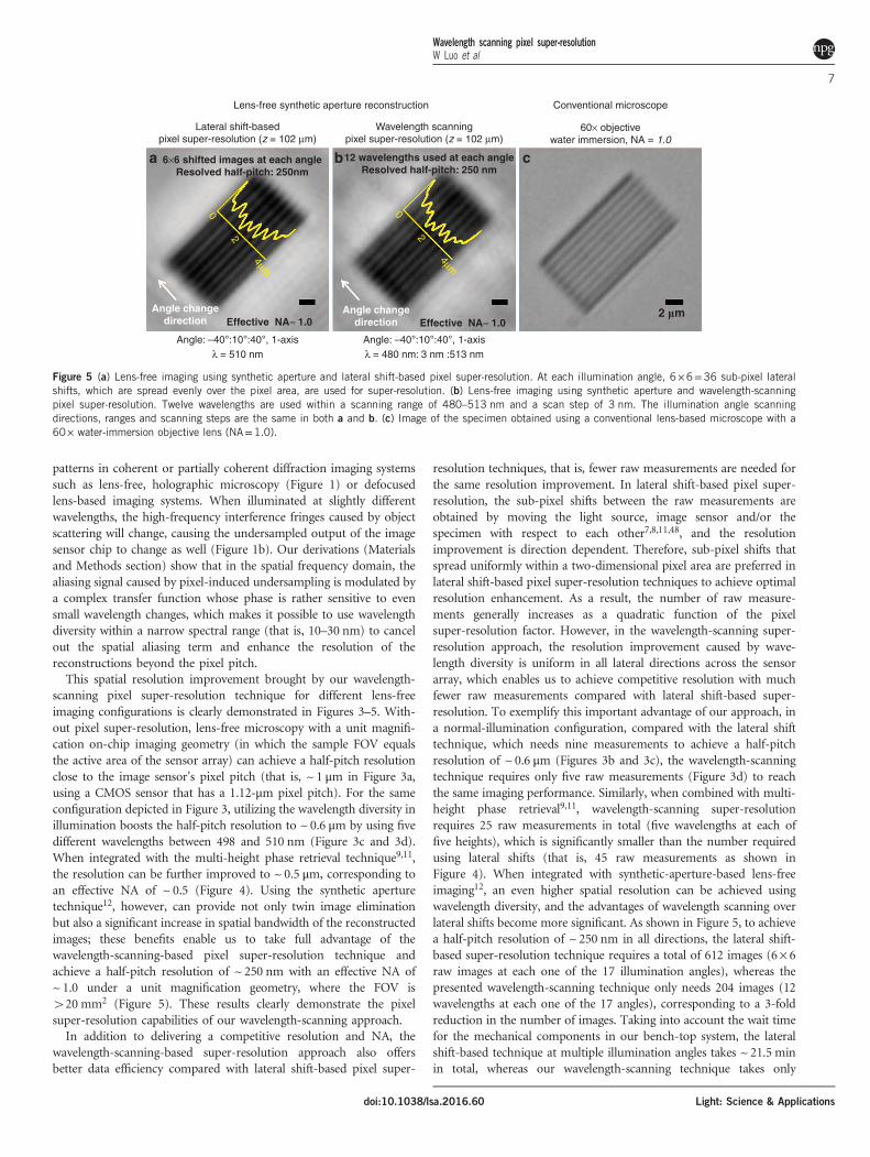
scanning pixel super-resolution technique for different lens-freeimaging configurations is clearly demonstrated in Figures 3–5. With-out pixel super-resolution, lens-free microscopy with a unit magnifi-cation on-chip imaging geometry (in which the sample FOV equalsthe active area of the sensor array) can achieve a half-pitch resolutionclose to the image sensor’s pixel pitch (that is, ~ 1 μm in Figure 3a,using a CMOS sensor that has a 1.12-μm pixel pitch). For the sameconfiguration depicted in Figure 3, utilizing the wavelength diversity inillumination boosts the half-pitch resolution to ~ 0.6 μm by using fivedifferent wavelengths between 498 and 510 nm (Figure 3c and 3d).When integrated with the multi-height phase retrieval technique9,11,the resolution can be further improved to ~ 0.5 μm, corresponding toan effective NA of ~ 0.5 (Figure 4). Using the synthetic aperturetechnique12, however, can provide not only twin image eliminationbut also a significant increase in spatial bandwidth of the reconstructedimages; these benefits enable us to take full advantage of thewavelength-scanning-based pixel super-resolution technique andachieve a half-pitch resolution of ~ 250 nm with an effective NA of~ 1.0 under a unit magnification geometry, where the FOV is420 mm2 (Figure 5). These results clearly demonstrate the pixelsuper-resolution capabilities of our wavelength-scanning approach.In addition to delivering a competitive resolution and NA, the
wavelength-scanning-based super-resolution approach also offersbetter data efficiency compared with lateral shift-based pixel super-
resolution techniques, that is, fewer raw measurements are needed forthe same resolution improvement. In lateral shift-based pixel super-resolution, the sub-pixel shifts between the raw measurements areobtained by moving the light source, image sensor and/or thespecimen with respect to each other7,8,11,48, and the resolutionimprovement is direction dependent. Therefore, sub-pixel shifts thatspread uniformly within a two-dimensional pixel area are preferred inlateral shift-based pixel super-resolution techniques to achieve optimalresolution enhancement. As a result, the number of raw measure-ments generally increases as a quadratic function of the pixelsuper-resolution factor. However, in the wavelength-scanning super-resolution approach, the resolution improvement caused by wave-length diversity is uniform in all lateral directions across the sensorarray, which enables us to achieve competitive resolution with muchfewer raw measurements compared with lateral shift-based super-resolution. To exemplify this important advantage of our approach, ina normal-illumination configuration, compared with the lateral shifttechnique, which needs nine measurements to achieve a half-pitchresolution of ~ 0.6 μm (Figures 3b and 3c), the wavelength-scanningtechnique requires only five raw measurements (Figure 3d) to reachthe same imaging performance. Similarly, when combined with multi-height phase retrieval9,11, wavelength-scanning super-resolutionrequires 25 raw measurements in total (five wavelengths at each offive heights), which is significantly smaller than the number requiredusing lateral shifts (that is, 45 raw measurements as shown inFigure 4). When integrated with synthetic-aperture-based lens-freeimaging12, an even higher spatial resolution can be achieved usingwavelength diversity, and the advantages of wavelength scanning overlateral shifts become more significant. As shown in Figure 5, to achievea half-pitch resolution of ~ 250 nm in all directions, the lateral shift-based super-resolution technique requires a total of 612 images (6× 6raw images at each one of the 17 illumination angles), whereas thepresented wavelength-scanning technique only needs 204 images (12wavelengths at each one of the 17 angles), corresponding to a 3-foldreduction in the number of images. Taking into account the wait timefor the mechanical components in our bench-top system, the lateralshift-based technique at multiple illumination angles takes ~ 21.5 minin total, whereas our wavelength-scanning technique takes only
Lens-free synthetic aperture reconstruction Conventional microscope
60× objectivewater immersion, NA = 1.0
Wavelength scanningpixel super-resolution (z = 102 μm)
6×6 shifted images at each angleResolved half-pitch: 250nm
Effective NA≈ 1.0 Effective NA≈ 1.02 �mAngle change
directionAngle change
direction
0
2
4μm
0
2
4μm
12 wavelengths used at each angleResolved half-pitch: 250 nm
Lateral shift-basedpixel super-resolution (z = 102 μm)
a b c
Angle: –40°:10°:40°, 1-axis Angle: –40°:10°:40°, 1-axisλ = 510 nm λ = 480 nm: 3 nm :513 nm
Figure 5 (a) Lens-free imaging using synthetic aperture and lateral shift-based pixel super-resolution. At each illumination angle, 6 ×6=36 sub-pixel lateralshifts, which are spread evenly over the pixel area, are used for super-resolution. (b) Lens-free imaging using synthetic aperture and wavelength-scanningpixel super-resolution. Twelve wavelengths are used within a scanning range of 480–513 nm and a scan step of 3 nm. The illumination angle scanningdirections, ranges and scanning steps are the same in both a and b. (c) Image of the specimen obtained using a conventional lens-based microscope with a60× water-immersion objective lens (NA=1.0).
Wavelength scanning pixel super-resolutionW Luo et al
7
Light: Science & Applicationsdoi:10.1038/lsa.2016.60
~4.8 min, showing a significant improvement in the imaging time.This important advantage in terms of the reduced number ofmeasurements can also be translated into smaller data storage space,which is critical for increasing the speed and utility of high-resolutionwide-field imaging techniques.We should re-emphasize that wavelength-scanning super-resolution
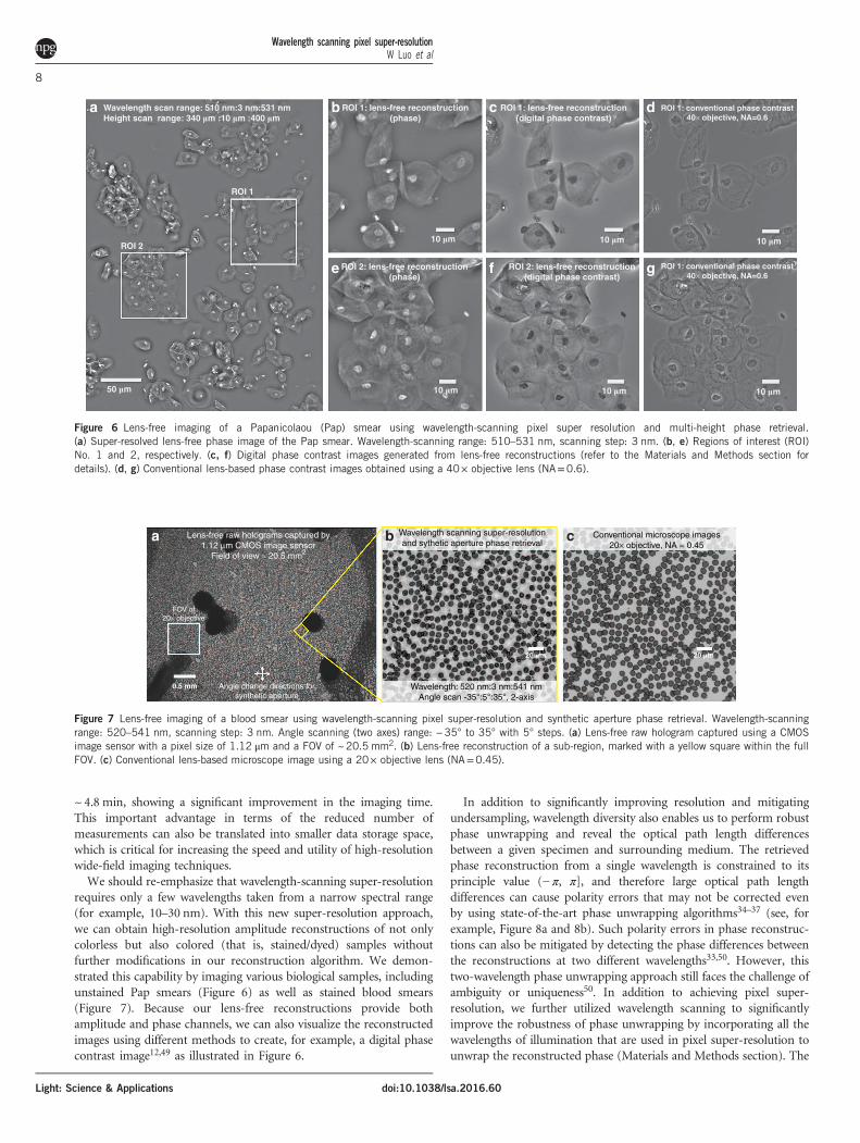
requires only a few wavelengths taken from a narrow spectral range(for example, 10–30 nm). With this new super-resolution approach,we can obtain high-resolution amplitude reconstructions of not onlycolorless but also colored (that is, stained/dyed) samples withoutfurther modifications in our reconstruction algorithm. We demon-strated this capability by imaging various biological samples, includingunstained Pap smears (Figure 6) as well as stained blood smears(Figure 7). Because our lens-free reconstructions provide bothamplitude and phase channels, we can also visualize the reconstructedimages using different methods to create, for example, a digital phasecontrast image12,49 as illustrated in Figure 6.
In addition to significantly improving resolution and mitigatingundersampling, wavelength diversity also enables us to perform robustphase unwrapping and reveal the optical path length differencesbetween a given specimen and surrounding medium. The retrievedphase reconstruction from a single wavelength is constrained to itsprinciple value (− π, π], and therefore large optical path lengthdifferences can cause polarity errors that may not be corrected evenby using state-of-the-art phase unwrapping algorithms34–37 (see, forexample, Figure 8a and 8b). Such polarity errors in phase reconstruc-tions can also be mitigated by detecting the phase differences betweenthe reconstructions at two different wavelengths33,50. However, thistwo-wavelength phase unwrapping approach still faces the challenge ofambiguity or uniqueness50. In addition to achieving pixel super-resolution, we further utilized wavelength scanning to significantlyimprove the robustness of phase unwrapping by incorporating all thewavelengths of illumination that are used in pixel super-resolution tounwrap the reconstructed phase (Materials and Methods section). The
a Lens-free raw holograms captured by1.12 μm CMOS image sensor
Field of view ≈ 20.5 mm2
Angle change directions forsynthetic aperture
FOV of20× objective
20 �m
0.5 mm
Wavelength scanning super-resolutionand sythetic aperture phase retrieval
Wavelength: 520 nm:3 nm:541 nmAngle scan -35°:5°:35°, 2-axis
Conventional microscope images20× objective, NA = 0.45
b c
20 �m
Figure 7 Lens-free imaging of a blood smear using wavelength-scanning pixel super-resolution and synthetic aperture phase retrieval. Wavelength-scanningrange: 520–541 nm, scanning step: 3 nm. Angle scanning (two axes) range: −35° to 35° with 5° steps. (a) Lens-free raw hologram captured using a CMOSimage sensor with a pixel size of 1.12 μm and a FOV of ~20.5 mm2. (b) Lens-free reconstruction of a sub-region, marked with a yellow square within the fullFOV. (c) Conventional lens-based microscope image using a 20× objective lens (NA=0.45).
a b c d
gfe
Wavelength scan range: 510 nm:3 nm:531 nmHeight scan range: 340 �m :10 �m :400 �m
ROI 1
ROI 2
50 �m
10 �m 10 �m 10 �m
10 �m 10 �m 10 �m
ROI 1: lens-free reconstruction(phase)
ROI 2: lens-free reconstruction(phase)
ROI 1: lens-free reconstruction(digital phase contrast)
ROI 2: lens-free reconstruction(digital phase contrast)
ROI 1: conventional phase contrast40× objective, NA=0.6
ROI 1: conventional phase contrast40× objective, NA=0.6
Figure 6 Lens-free imaging of a Papanicolaou (Pap) smear using wavelength-scanning pixel super resolution and multi-height phase retrieval.(a) Super-resolved lens-free phase image of the Pap smear. Wavelength-scanning range: 510–531 nm, scanning step: 3 nm. (b, e) Regions of interest (ROI)No. 1 and 2, respectively. (c, f) Digital phase contrast images generated from lens-free reconstructions (refer to the Materials and Methods section fordetails). (d, g) Conventional lens-based phase contrast images obtained using a 40× objective lens (NA=0.6).
Wavelength scanning pixel super-resolutionW Luo et al
8
Light: Science & Applications doi:10.1038/lsa.2016.60
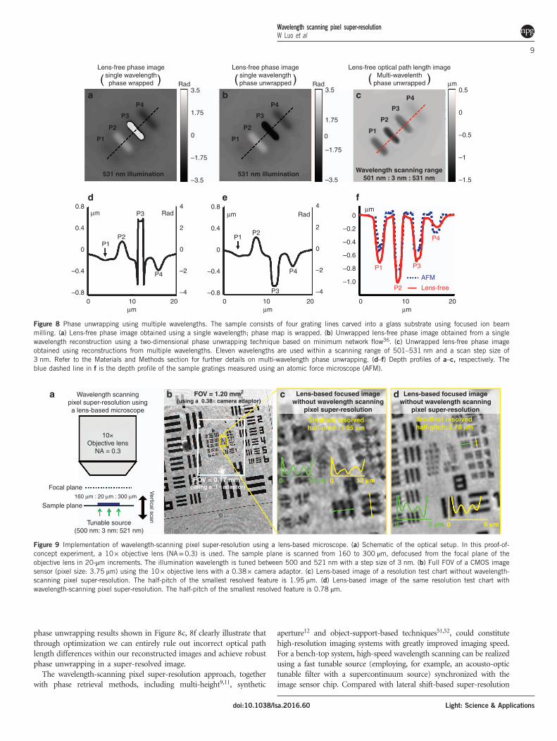
phase unwrapping results shown in Figure 8c, 8f clearly illustrate thatthrough optimization we can entirely rule out incorrect optical pathlength differences within our reconstructed images and achieve robustphase unwrapping in a super-resolved image.The wavelength-scanning pixel super-resolution approach, together
with phase retrieval methods, including multi-height9,11, synthetic
aperture12 and object-support-based techniques51,52, could constitutehigh-resolution imaging systems with greatly improved imaging speed.For a bench-top system, high-speed wavelength scanning can be realizedusing a fast tunable source (employing, for example, an acousto-optictunable filter with a supercontinuum source) synchronized with theimage sensor chip. Compared with lateral shift-based super-resolution
μm0.5
RadRad3.5
1.75
0
–1.75
–3.5
3.5
d e f
ba c
1.75
0
–1.75
–3.5
4
2
0
–2
–420100
–0.8
–0.4
0
0.4
0.8μm
μm μm20100
μm
P3
P2P1
Rad4
2
0
–2
–4–0.8
–0.4
0.4
0
0.8μm
P4
P3
P2P1
Rad
P4
0
–0.5
–1
–1.5
20100
μm
P4
P3P1
P2 Lens-free
AFM–1.0
–0.8
–0.6
–0.4
–0.2
0
Lens-free phase imagesingle wavelengthphase wrapped
P4
P3
P2
P1
P4
P3
P2
P1
P4
P3
P2
P1
Wavelength scanning range501 nm : 3 nm : 531 nm
531 nm illumination 531 nm illumination
( )Lens-free phase image
single wavelengthphase unwrapped( )
Lens-free optical path length imageMulti-wavelenth
phase unwrapped( )
Figure 8 Phase unwrapping using multiple wavelengths. The sample consists of four grating lines carved into a glass substrate using focused ion beammilling. (a) Lens-free phase image obtained using a single wavelength; phase map is wrapped. (b) Unwrapped lens-free phase image obtained from a singlewavelength reconstruction using a two-dimensional phase unwrapping technique based on minimum network flow36. (c) Unwrapped lens-free phase imageobtained using reconstructions from multiple wavelengths. Eleven wavelengths are used within a scanning range of 501–531 nm and a scan step size of3 nm. Refer to the Materials and Methods section for further details on multi-wavelength phase unwrapping. (d–f) Depth profiles of a–c, respectively. Theblue dashed line in f is the depth profile of the sample gratings measured using an atomic force microscope (AFM).
FOV = 0.17 mm2
(using a 1× adaptor)
Wavelength scanningpixel super-resolution usinga lens-based microscope
Focal plane Vertical scan
Sample plane
Tunable source(500 nm: 3 nm: 521 nm)
10×Objective lens
NA = 0.3
160 μm : 20 μm : 300 μm
b FOV = 1.20 mm2
(using a 0.38× camera adaptor)Lens-based focused image
without wavelength scanningpixel super-resolution
Lens-based focused imagewithout wavelength scanning
pixel super-resolution
Smallest resolvedhalf-pitch: 1.95 �m
0 12 �m 0 12 �m
0 5 �m 0 6 �m
Smallest resolvedhalf-pitch: 0.78 �m
a c d
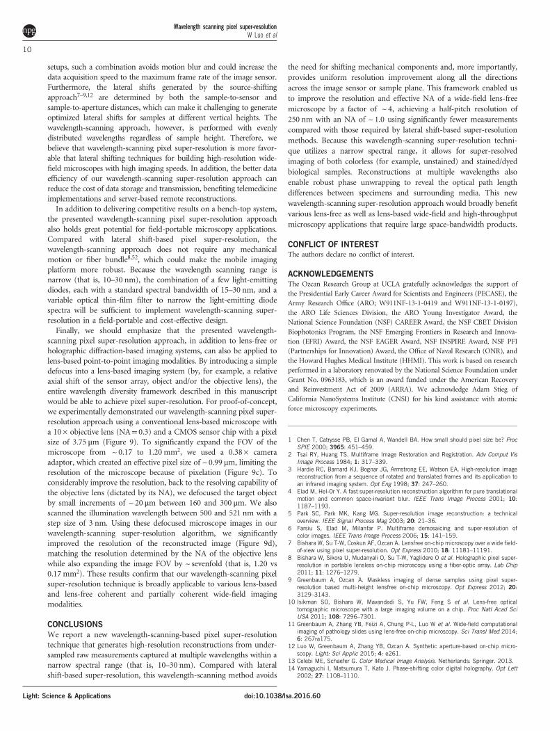
Figure 9 Implementation of wavelength-scanning pixel super-resolution using a lens-based microscope. (a) Schematic of the optical setup. In this proof-of-concept experiment, a 10× objective lens (NA=0.3) is used. The sample plane is scanned from 160 to 300 μm, defocused from the focal plane of theobjective lens in 20-μm increments. The illumination wavelength is tuned between 500 and 521 nm with a step size of 3 nm. (b) Full FOV of a CMOS imagesensor (pixel size: 3.75 μm) using the 10× objective lens with a 0.38× camera adaptor. (c) Lens-based image of a resolution test chart without wavelength-scanning pixel super-resolution. The half-pitch of the smallest resolved feature is 1.95 μm. (d) Lens-based image of the same resolution test chart withwavelength-scanning pixel super-resolution. The half-pitch of the smallest resolved feature is 0.78 μm.
Wavelength scanning pixel super-resolutionW Luo et al
9
Light: Science & Applicationsdoi:10.1038/lsa.2016.60
setups, such a combination avoids motion blur and could increase thedata acquisition speed to the maximum frame rate of the image sensor.Furthermore, the lateral shifts generated by the source-shiftingapproach7–9,12 are determined by both the sample-to-sensor andsample-to-aperture distances, which can make it challenging to generateoptimized lateral shifts for samples at different vertical heights. Thewavelength-scanning approach, however, is performed with evenlydistributed wavelengths regardless of sample height. Therefore, webelieve that wavelength-scanning pixel super-resolution is more favor-able that lateral shifting techniques for building high-resolution wide-field microscopes with high imaging speeds. In addition, the better dataefficiency of our wavelength-scanning super-resolution approach canreduce the cost of data storage and transmission, benefiting telemedicineimplementations and server-based remote reconstructions.In addition to delivering competitive results on a bench-top system,
the presented wavelength-scanning pixel super-resolution approachalso holds great potential for field-portable microscopy applications.Compared with lateral shift-based pixel super-resolution, thewavelength-scanning approach does not require any mechanicalmotion or fiber bundle8,52, which could make the mobile imagingplatform more robust. Because the wavelength scanning range isnarrow (that is, 10–30 nm), the combination of a few light-emittingdiodes, each with a standard spectral bandwidth of 15–30 nm, and avariable optical thin-film filter to narrow the light-emitting diodespectra will be sufficient to implement wavelength-scanning super-resolution in a field-portable and cost-effective design.Finally, we should emphasize that the presented wavelength-
scanning pixel super-resolution approach, in addition to lens-free orholographic diffraction-based imaging systems, can also be applied tolens-based point-to-point imaging modalities. By introducing a simpledefocus into a lens-based imaging system (by, for example, a relativeaxial shift of the sensor array, object and/or the objective lens), theentire wavelength diversity framework described in this manuscriptwould be able to achieve pixel super-resolution. For proof-of-concept,we experimentally demonstrated our wavelength-scanning pixel super-resolution approach using a conventional lens-based microscope witha 10× objective lens (NA= 0.3) and a CMOS sensor chip with a pixelsize of 3.75 μm (Figure 9). To significantly expand the FOV of themicroscope from ~0.17 to 1.20 mm2, we used a 0.38× cameraadaptor, which created an effective pixel size of ~ 0.99 μm, limiting theresolution of the microscope because of pixelation (Figure 9c). Toconsiderably improve the resolution, back to the resolving capability ofthe objective lens (dictated by its NA), we defocused the target objectby small increments of ~ 20 μm between 160 and 300 μm. We alsoscanned the illumination wavelength between 500 and 521 nm with astep size of 3 nm. Using these defocused microscope images in ourwavelength-scanning super-resolution algorithm, we significantlyimproved the resolution of the reconstructed image (Figure 9d),matching the resolution determined by the NA of the objective lenswhile also expanding the image FOV by ~ sevenfold (that is, 1.20 vs0.17 mm2). These results confirm that our wavelength-scanning pixelsuper-resolution technique is broadly applicable to various lens-basedand lens-free coherent and partially coherent wide-field imagingmodalities.
CONCLUSIONS
We report a new wavelength-scanning-based pixel super-resolutiontechnique that generates high-resolution reconstructions from under-sampled raw measurements captured at multiple wavelengths within anarrow spectral range (that is, 10–30 nm). Compared with lateralshift-based super-resolution, this wavelength-scanning method avoids
the need for shifting mechanical components and, more importantly,provides uniform resolution improvement along all the directionsacross the image sensor or sample plane. This framework enabled usto improve the resolution and effective NA of a wide-field lens-freemicroscope by a factor of ~ 4, achieving a half-pitch resolution of250 nm with an NA of ~ 1.0 using significantly fewer measurementscompared with those required by lateral shift-based super-resolutionmethods. Because this wavelength-scanning super-resolution techni-que utilizes a narrow spectral range, it allows for super-resolvedimaging of both colorless (for example, unstained) and stained/dyedbiological samples. Reconstructions at multiple wavelengths alsoenable robust phase unwrapping to reveal the optical path lengthdifferences between specimens and surrounding media. This newwavelength-scanning super-resolution approach would broadly benefitvarious lens-free as well as lens-based wide-field and high-throughputmicroscopy applications that require large space-bandwidth products.
CONFLICT OF INTERESTThe authors declare no conflict of interest.
ACKNOWLEDGEMENTS
The Ozcan Research Group at UCLA gratefully acknowledges the support ofthe Presidential Early Career Award for Scientists and Engineers (PECASE), theArmy Research Office (ARO; W911NF-13-1-0419 and W911NF-13-1-0197),the ARO Life Sciences Division, the ARO Young Investigator Award, theNational Science Foundation (NSF) CAREER Award, the NSF CBET DivisionBiophotonics Program, the NSF Emerging Frontiers in Research and Innova-tion (EFRI) Award, the NSF EAGER Award, NSF INSPIRE Award, NSF PFI(Partnerships for Innovation) Award, the Office of Naval Research (ONR), andthe Howard Hughes Medical Institute (HHMI). This work is based on researchperformed in a laboratory renovated by the National Science Foundation underGrant No. 0963183, which is an award funded under the American Recoveryand Reinvestment Act of 2009 (ARRA). We acknowledge Adam Stieg ofCalifornia NanoSystems Institute (CNSI) for his kind assistance with atomicforce microscopy experiments.
1 Chen T, Catrysse PB, El Gamal A, Wandell BA. How small should pixel size be? ProcSPIE 2000; 3965: 451–459.
2 Tsai RY, Huang TS. Multiframe Image Restoration and Registration. Adv Comput VisImage Process 1984; 1: 317–339.
3 Hardie RC, Barnard KJ, Bognar JG, Armstrong EE, Watson EA. High-resolution imagereconstruction from a sequence of rotated and translated frames and its application toan infrared imaging system. Opt Eng 1998; 37: 247–260.
4 Elad M, Hel-Or Y. A fast super-resolution reconstruction algorithm for pure translationalmotion and common space-invariant blur. IEEE Trans Image Process 2001; 10:1187–1193.
5 Park SC, Park MK, Kang MG. Super-resolution image reconstruction: a technicaloverview. IEEE Signal Process Mag 2003; 20: 21–36.
6 Farsiu S, Elad M, Milanfar P. Multiframe demosaicing and super-resolution ofcolor images. IEEE Trans Image Process 2006; 15: 141–159.
7 Bishara W, Su T-W, Coskun AF, Ozcan A. Lensfree on-chip microscopy over a wide field-of-view using pixel super-resolution. Opt Express 2010; 18: 11181–11191.
8 Bishara W, Sikora U, Mudanyali O, Su T-W, Yaglidere O et al. Holographic pixel super-resolution in portable lensless on-chip microscopy using a fiber-optic array. Lab Chip2011; 11: 1276–1279.
9 Greenbaum A, Ozcan A. Maskless imaging of dense samples using pixel super-resolution based multi-height lensfree on-chip microscopy. Opt Express 2012; 20:3129–3143.
10 Isikman SO, Bishara W, Mavandadi S, Yu FW, Feng S et al. Lens-free opticaltomographic microscope with a large imaging volume on a chip. Proc Natl Acad SciUSA 2011; 108: 7296–7301.
11 Greenbaum A, Zhang YB, Feizi A, Chung P-L, Luo W et al. Wide-field computationalimaging of pathology slides using lens-free on-chip microscopy. Sci Transl Med 2014;6: 267ra175.
12 Luo W, Greenbaum A, Zhang YB, Ozcan A. Synthetic aperture-based on-chip micro-scopy. Light: Sci Applic 2015; 4: e261.
13 Celebi ME, Schaefer G. Color Medical Image Analysis. Netherlands: Springer. 2013.14 Yamaguchi I, Matsumura T, Kato J. Phase-shifting color digital holography. Opt Lett
2002; 27: 1108–1110.
Wavelength scanning pixel super-resolutionW Luo et al
10
Light: Science & Applications doi:10.1038/lsa.2016.60
15 Kato J, Yamaguchi I, Matsumura T. Multicolor digital holography with an achromaticphase shifter. Opt Lett 2002; 27: 1403–1405.
16 Ferraro P, Grilli S, Miccio L, Alfieri D, De Nicola S et al. Full color 3-D Imaging by digitalholography and removal of chromatic aberrations. J Display Technol 2008; 4: 97–100.
17 Picart P, Tankam P, Mounier D, Peng ZJ, Li JC. Spatial bandwidth extended reconstruc-tion for digital color Fresnel holograms. Opt Express 2009; 17: 9145–9156.
18 Kakue T, Tahara T, Ito K, Shimozato Y, Awatsuji Y et al. Parallel phase-shifting colordigital holography using two phase shifts. Appl Opt 2009; 48: H244–H250.
19 Isikman SO, Sencan I, Mudanyali O, Bishara W, Oztoprak C et al. Color andmonochrome lensless on-chip imaging of Caenorhabditis elegans over a wide field-of-view. Lab Chip 2010; 10: 1109–1112.
20 Garcia-Sucerquia J. Color lensless digital holographic microscopy with micrometerresolution. Opt Lett 2012; 37: 1724–1726.
21 Ito Y, Shimozato Y, Xia P, Tahara T, Kakue T et al. Four-wavelength color digitalholography. J Display Technol 2012; 8: 570–576.
22 Greenbaum A, Feizi A, Akbari N, Ozcan A. Wide-field computational color imaging usingpixel super-resolved on-chip microscopy. Opt Express 2013; 21: 12469–12483.
23 Mendoza-Yero O, Tajahuerce E, Lancis J, Garcia-Sucerquia J. Diffractive digitallensless holographic microscopy with fine spectral tuning. Opt Letters 2013; 38:2107–2109.
24 Kiss MZ, Nagy BJ, Lakatos P, Göröcs Z, Tőkés S et al. Special multicolor illuminationand numerical tilt correction in volumetric digital holographic microscopy. Opt Express2014; 22: 7559–7573.
25 Dohet-Eraly J, Yourassowsky C, Dubois F. Color imaging-in-flow by digital holographicmicroscopy with permanent defect and aberration corrections. Opt Lett 2014; 39:6070–6073.
26 Bao P, Zhang FC, Pedrini G, Osten W. Phase retrieval using multiple illuminationwavelengths. Opt Lett 2008; 33: 309–311.
27 Bao P, Situ G, Pedrini G, Osten W. Lensless phase microscopy using phase retrievalwith multiple illumination wavelengths. Appl Opt 2012; 51: 5486–5494.
28 Noom DWE, Boonzajer Flaes DE, Labordus E, Eikema KSE, Witte S. High-speed multi-wavelength Fresnel diffraction imaging. Opt Express 2014; 22: 30504–30511.
29 Sanz M, Picazo-Bueno JA, García J, Micó V. Improved quantitative phase imaging inlensless microscopy by single-shot multi-wavelength illumination using a fast conver-gence algorithm. Opt Express 2015; 23: 21352–21365.
30 Kazemzadeh F, Jin C, Molladavoodi S, Mei Y, Emelko MB et al. Lens-free spectral light-field fusion microscopy for contrast- and resolution-enhanced imaging of biologicalspecimens. Opt Lett 2015; 40: 3862–3865.
31 Kühn J, Colomb T, Montfort F, Charrière F, Emery Y et al. Real-time dual-wavelengthdigital holographic microscopy with a single hologram acquisition. Opt Express 2007;15: 7231–7242.
32 Desse J-M, Picart P, Tankam P. Digital three-color holographic interferometry for flowanalysis. Opt Express 2008; 16: 5471–5480.
33 Khmaladze A, Kim M, Lo C-M. Phase imaging of cells by simultaneous dual-wavelengthreflection digital holography. Opt Express 2008; 16: 10900–10911.
34 Itoh K. Analysis of the phase unwrapping algorithm. Appl Opt 1982; 21: 2470.35 Takeda M, Gu Q, Kinoshita M, Takai H, Takahashi Y. Frequency-multiplex Fourier-
transform profilometry: a single-shot three-dimensional shape measurement of objectswith large height discontinuities and/or surface isolations. Appl Opt 1997; 36:5347–5354.
36 Costantini M. A novel phase unwrapping method based on network programming. IEEETrans Geosci Remote Sens 1998; 36: 813–821.
37 Volkov VV, Zhu YM. Deterministic phase unwrapping in the presence of noise. Opt Lett2003; 28: 2156–2158.
38 Shen PF, Patterson LT. A simplified wright’s stain technique for routine avian bloodsmear staining. Poultry Sci 1983; 62: 923–924.
39 Oppenheim AV, Willsky AS, Nawab SH. Signals and Systems, 2nd edn. New York:Prentice Hall, 1996.
40 Greenbaum A, Luo W, Khademhosseinieh B, Su TW, Coskun AF et al. Increased space-bandwidth product in pixel super-resolved lensfree on-chip microscopy. Scientific Rep2013; 3: 1717.
41 Gonzalez RC, Woods RE. Digital Image Processing, 3rd edn. New York: Prentice Hall,2007.
42 Goodman J. Introduction to Fourier Optics, 3rd edn. California: Roberts and CompanyPublishers, 2004.
43 Allen LJ, McBride W, O’Leary NL, Oxley MP. Exit wave reconstruction at atomicresolution. Ultramicroscopy 2004; 100: 91–104.
44 Fienup JR. Reconstruction of an object from the modulus of its Fourier transform. OptLett 1978; 3: 27–29.
45 Fienup JR. Phase retrieval algorithms: a comparison. Appl Opt 1982; 21: 2758–2769.46 Zhang Y, Pedrini G, Osten W, Tiziani H. Whole optical wave field reconstruction from
double or multi in-line holograms by phase retrieval algorithm. Opt Express 2003; 11:3234–3241.
47 Boyd S, Vandenberghe L. Convex Optimization. Cambridge, UK: Cambridge UniversityPress, 2004.
48 Greenbaum A, Luo W, Su T-W, Göröcs Z, Xue L et al. Imaging without lenses:achievements and remaining challenges of wide-field on-chip microscopy. Nat Methods2012; 9: 889–895.
49 Zernike F. Phase contrast, a new method for the microscopic observation of transparentobjects. Physica 1942; 9: 686–698.
50 Gass J, Dakoff A, Kim MK. Phase imaging without 2π ambiguity by multiwavelengthdigital holography. Opt Lett 2003; 28: 1141–1143.
51 Mudanyali O, Tseng D, Oh C, Isikman SO, Sencan I et al. Compact, light-weight andcost-effective microscope based on lensless incoherent holography for telemedicineapplications. Lab Chip 2010; 10: 1417–1428.
52 Greenbaum A, Sikora U, Ozcan A. Field-portable wide-field microscopy of densesamples using multi-height pixel super-resolution based lensfree imaging. Lab Chip2012; 12: 1242–1245.
This work is licensed under a Creative CommonsAttribution-NonCommercial-NoDerivs 4.0 International
License. The images or other third party material in this article areincluded in the article’s Creative Commons license, unless indicatedotherwise in the credit line; if the material is not included under theCreativeCommons license, userswill need to obtain permission from thelicense holder to reproduce the material. To view a copy of this license,visit http://creativecommons.org/licenses/by-nc-nd/4.0/
Supplementary Information for this article can be found on the Light: Science & Applications' website (http://www.nature.com/lsa).
Wavelength scanning pixel super-resolutionW Luo et al
11
Light: Science & Applicationsdoi:10.1038/lsa.2016.60