Embed Size (px)
Citation preview

Pix4Dmapper
Getting Started
Sign-up 2
Redeem 3
Hardware - Computer 3
Software Download and Installation 4 Download 4 Installation 4 Language settings 7 Update 8 License deactivation 8
Inputs 9
Outputs 9
Image Acquisition Plan 10 General Case 10 Building reconstruction 11 City reconstruction - visible facades 12
Processing Options Templates 13
How to create a project 15 Creating a New Project 15 Importing the Images 17 Configuring the Image Properties 17 Selecting the Output / GCP Coordinate System 18 Selecting the Processing Options Template 20
Processing Steps 21 1. Initial Processing 21 2. Point Cloud and Mesh 21 3. DSM, Orthomosaic and Index 21
Ground Control Points (GCPs) 22 Instructions 22
1
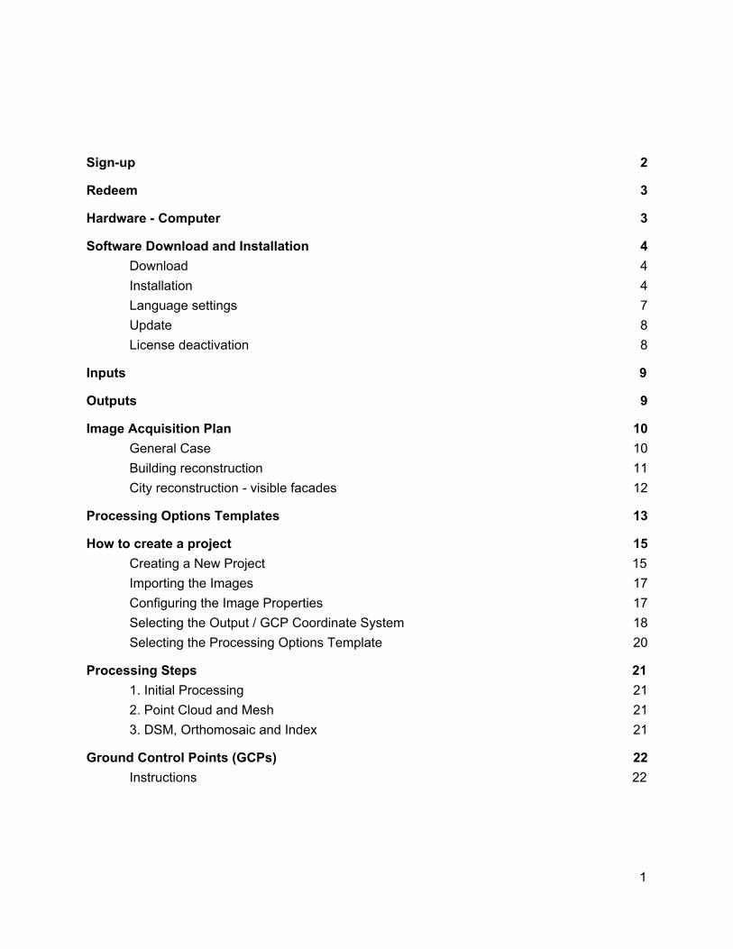
Sign-up Please follow these steps to create a Pix4D user account:
1. Click the link or copy paste it into your favorite browser: https://cloud.pix4d.com/signup/ 2. Complete the sign-up page with your information:
3. Click CREATE ACCOUNT. 4. A verification email will be sent to activate the account. Open the email and click
Confirm my email. 5. The Pix4D user account is created and confirmed.
2
Redeem If the license is not already assigned to your account via an e-commerce purchase. The license redeem makes sure that you are the owner of your license. First, make sure that you have a Pix4D account. If not, create a Pix4D account as described in section Sign-up. The steps to redeem the license are:
1. Click the link under Activation Instructions in the License Certificate you have received when purchasing the Pix4D license. Or go to: https://cloud.pix4d.com/license-redeem/
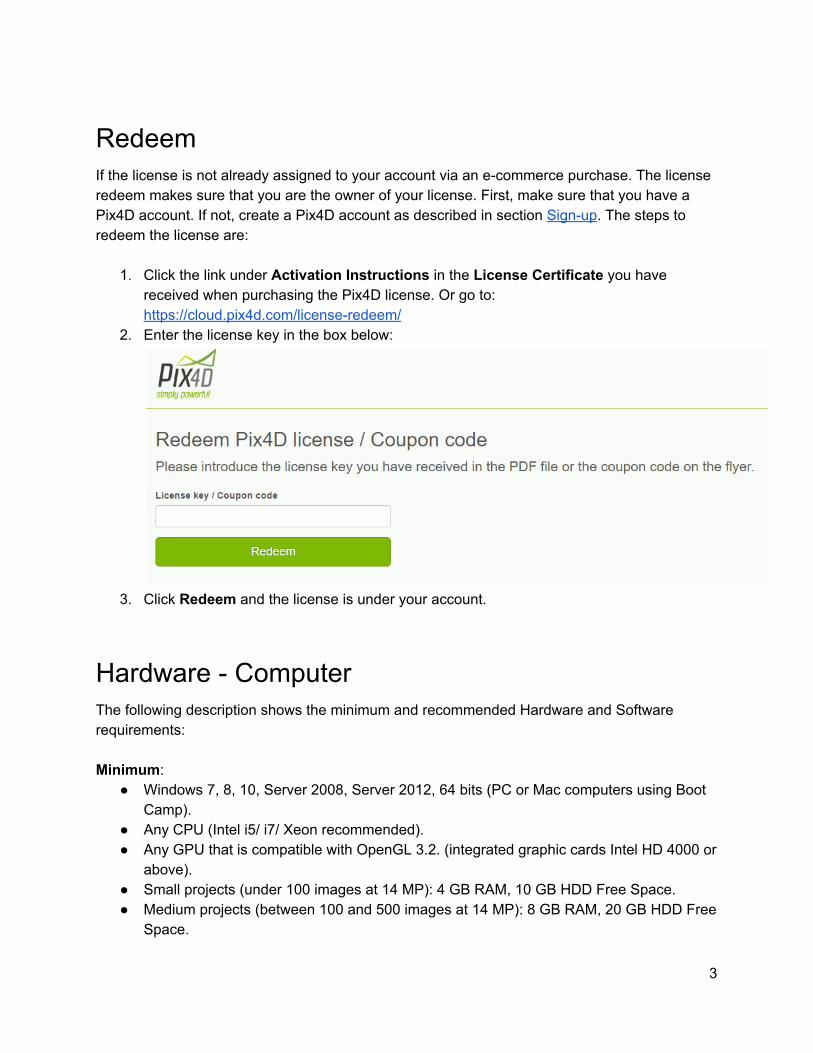
2. Enter the license key in the box below:
3. Click Redeem and the license is under your account.
Hardware - Computer The following description shows the minimum and recommended Hardware and Software requirements: Minimum:
● Windows 7, 8, 10, Server 2008, Server 2012, 64 bits (PC or Mac computers using Boot Camp).
● Any CPU (Intel i5/ i7/ Xeon recommended). ● Any GPU that is compatible with OpenGL 3.2. (integrated graphic cards Intel HD 4000 or
above). ● Small projects (under 100 images at 14 MP): 4 GB RAM, 10 GB HDD Free Space. ● Medium projects (between 100 and 500 images at 14 MP): 8 GB RAM, 20 GB HDD Free
Space.
3
● Large projects (between 500 and 2000 images at 14 MP): 16 GB RAM, 40 GB HDD Free Space.
● Very Large projects (over 2000 images at 14 MP): 16 GB RAM, 80 GB HDD Free Space. Recommended:
● Windows 7, 8, 10 64 bits. ● CPU quad-core or hexa-core Intel i7/Xeon. ● GeForce GPU compatible with OpenGL 3.2 and 2 GB RAM. ● Hard disk: SSD. ● Small projects (under 100 images at 14 MP): 8 GB RAM, 15 GB SSD Free Space. ● Medium projects (between 100 and 500 images at 14 MP): 16GB RAM, 30 GB SSD
Free Space. ● Large projects (over 500 images at 14 MP): 32 GB RAM, 60 GB SSD Free Space. ● Very Large projects (over 2000 images at 14 MP): 64 GB RAM, 120 GB SSD Free
Space.
Software Download and Installation At any given time there are two versions available to download:
● Pix4D Desktop: This version is meant for production work. ● Pix4D Desktop Preview: This version contains the newest features, but is not meant for
production work.
Download To download the software:
1. Go to: https://cloud.pix4d.com/download/. 2. Download Pix4D Desktop or Pix4D Desktop Preview.
Installation Once the software has been downloaded, install it using the following steps:
1. Double click the downloaded file. The Pix4Dmapper Setup wizard starts.
4
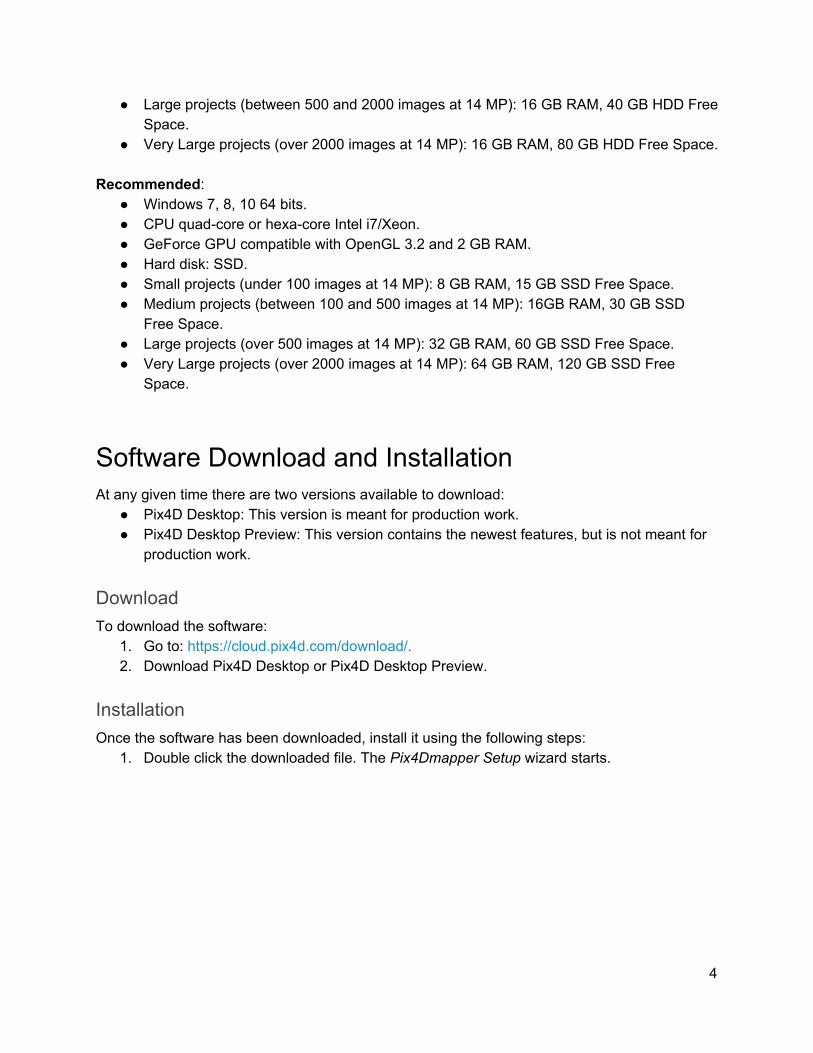
2. (optional): If the Open file - Security Warning pop-up appears, click Run.
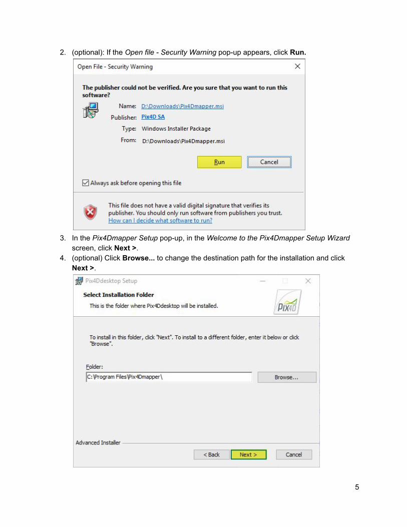
3. In the Pix4Dmapper Setup pop-up, in the Welcome to the Pix4Dmapper Setup Wizard
screen, click Next >. 4. (optional) Click Browse... to change the destination path for the installation and click
Next >.
5
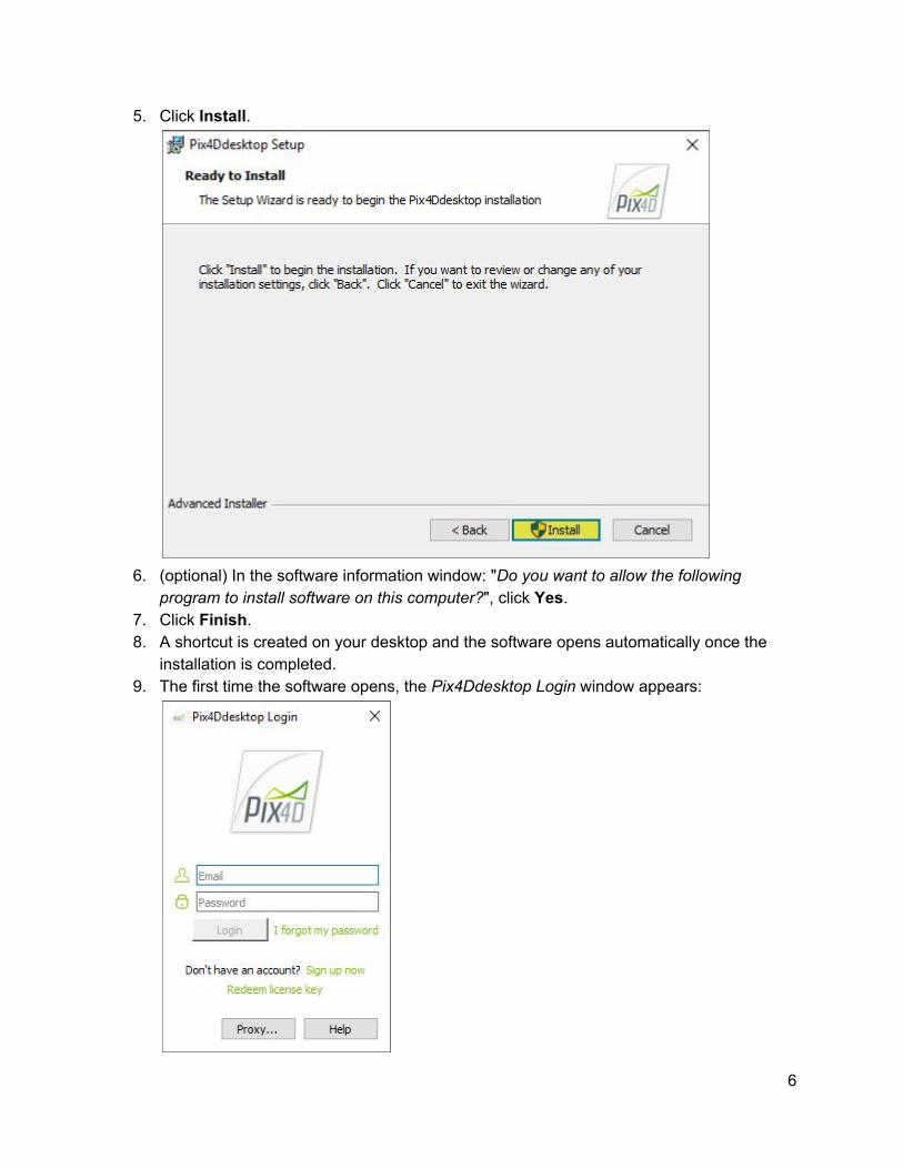
5. Click Install.
6. (optional) In the software information window: "Do you want to allow the following
program to install software on this computer?", click Yes. 7. Click Finish. 8. A shortcut is created on your desktop and the software opens automatically once the
installation is completed. 9. The first time the software opens, the Pix4Ddesktop Login window appears:
6
10. Type the Email and Password of the account and click Login. 11. Read the End-User License Agreement, select I accept the terms in the License
Agreement and click Next. 12. Select one of these options:
a. Request Pix4Dmapper now (Free Trial) to activate a 15-day trial. b. Use Pix4Ddiscovery to activate the limited version. c. Choose a license to select among existing licenses on the account.
13. Click OK. Pix4D Desktop is now ready for processing.
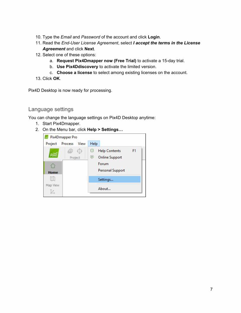
Language settings You can change the language settings on Pix4D Desktop anytime:
1. Start Pix4Dmapper. 2. On the Menu bar, click Help > Settings…
7
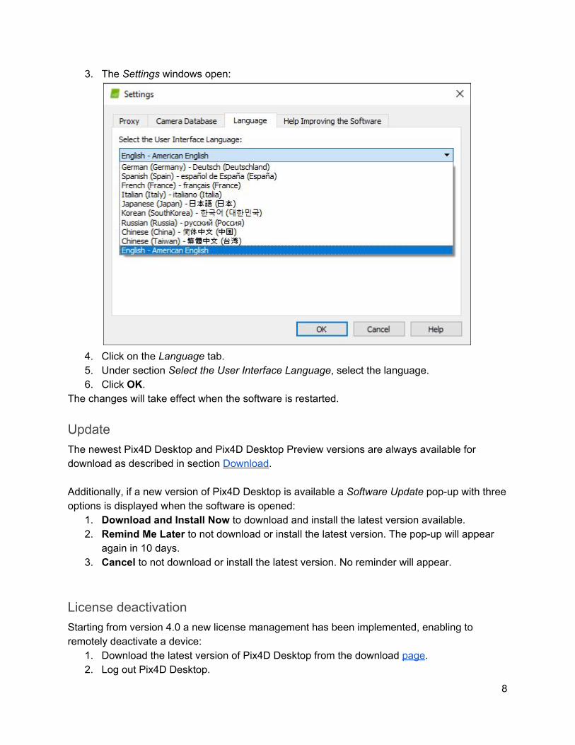
3. The Settings windows open:
4. Click on the Language tab. 5. Under section Select the User Interface Language, select the language. 6. Click OK.
The changes will take effect when the software is restarted.
Update The newest Pix4D Desktop and Pix4D Desktop Preview versions are always available for download as described in section Download. Additionally, if a new version of Pix4D Desktop is available a Software Update pop-up with three options is displayed when the software is opened:
1. Download and Install Now to download and install the latest version available. 2. Remind Me Later to not download or install the latest version. The pop-up will appear
again in 10 days. 3. Cancel to not download or install the latest version. No reminder will appear.
License deactivation Starting from version 4.0 a new license management has been implemented, enabling to remotely deactivate a device:
1. Download the latest version of Pix4D Desktop from the download page. 2. Log out Pix4D Desktop.
8
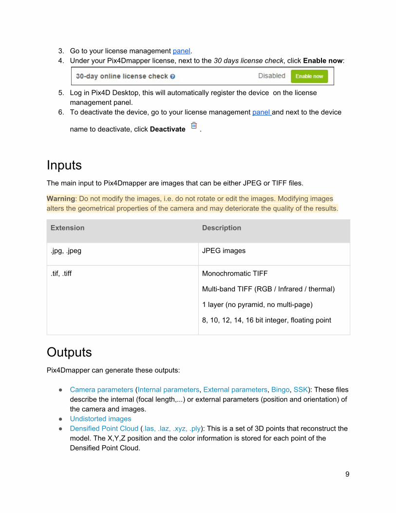
3. Go to your license management panel. 4. Under your Pix4Dmapper license, next to the 30 days license check, click Enable now:
5. Log in Pix4D Desktop, this will automatically register the device on the license
management panel. 6. To deactivate the device, go to your license management panel and next to the device
name to deactivate, click Deactivate .
Inputs The main input to Pix4Dmapper are images that can be either JPEG or TIFF files.
Warning: Do not modify the images, i.e. do not rotate or edit the images. Modifying images alters the geometrical properties of the camera and may deteriorate the quality of the results.
Extension Description
.jpg, .jpeg JPEG images
.tif, .tiff Monochromatic TIFF
Multi-band TIFF (RGB / Infrared / thermal)
1 layer (no pyramid, no multi-page)
8, 10, 12, 14, 16 bit integer, floating point
Outputs Pix4Dmapper can generate these outputs:
● Camera parameters (Internal parameters, External parameters, Bingo, SSK): These files describe the internal (focal length,...) or external parameters (position and orientation) of the camera and images.
● Undistorted images ● Densified Point Cloud (.las, .laz, .xyz, .ply): This is a set of 3D points that reconstruct the
model. The X,Y,Z position and the color information is stored for each point of the Densified Point Cloud.
9
● Digital Surface Model (Grid DSM, Raster DSM): This is a 2.5 D model of the mapped area that contains (X,Y,Z) information, but no color information.
● Digital Terrain Model (DTM: Raster DTM): This is a 2.5 D model of the mapped area after filtering out objects such as buildings, that contains (X,Y,Z) information but no color information.
● Orthomosaic (GeoTIFF, KML file, Google Maps HTML file): 2D model (map) made by blending several orthophotos. Color balanced to be visually pleasing.
● Index Map (GeoTIFF, Colored KML file, Grid Shapefile): To each index is associated an index map. For each pixel on this map, the value of the pixel is derived from the associated reflectance maps.
● 3D Textured Mesh (.obj, .fbx, .dxf, .ply, .pdf, .osgb, .slpk): This is a representation of the shape of the model that consists of vertices, edges, faces and the texture from the images that is projected on it. It is useful to present and visualize the model, share it and upload it to online platforms such as Sketchfab.
● Contour lines (shp, .pdf, .dxf): These are lines connecting points of equal elevation. They are useful because they allow to better understand the shape of the land surface (the topography) on a map.
● Video animation (.mp4, .mkv, .avi) ● 3D Digitized objects: Polyline, Surface, Volume base surface (.shp, .dxf,.kml, .dgn)
Image Acquisition Plan The image acquisition plan depends on the:
● Type of terrain / object to be reconstructed. ● Ground Sampling Distance (GSD): The GSD required by the project specifications will
define the distance (flight height) at which the images have to be taken. For example a GSD of 5 cm means that one pixel in the image represents linearly 5 cm on the ground (5*5 = 25 square centimeters).
● Overlap: The overlap depends on the type of terrain that is mapped and will determine the rate at which the images have to be taken.
A bad image acquisition plan will lead to inaccurate results or processing failure and will require to acquire images again. All flight plans described below can be flown automatically with the flight planning app Pix4Dcapture available on Android and iOS.
General Case For most cases it is recommended to acquire the images with a regular grid pattern. The recommended overlap is at least 75% frontal overlap (with respect to the flight direction) and at least 60% side overlap (between flying tracks). The camera should be maintained as much possible at a constant height over the terrain / object to ensure the desired GSD.
10
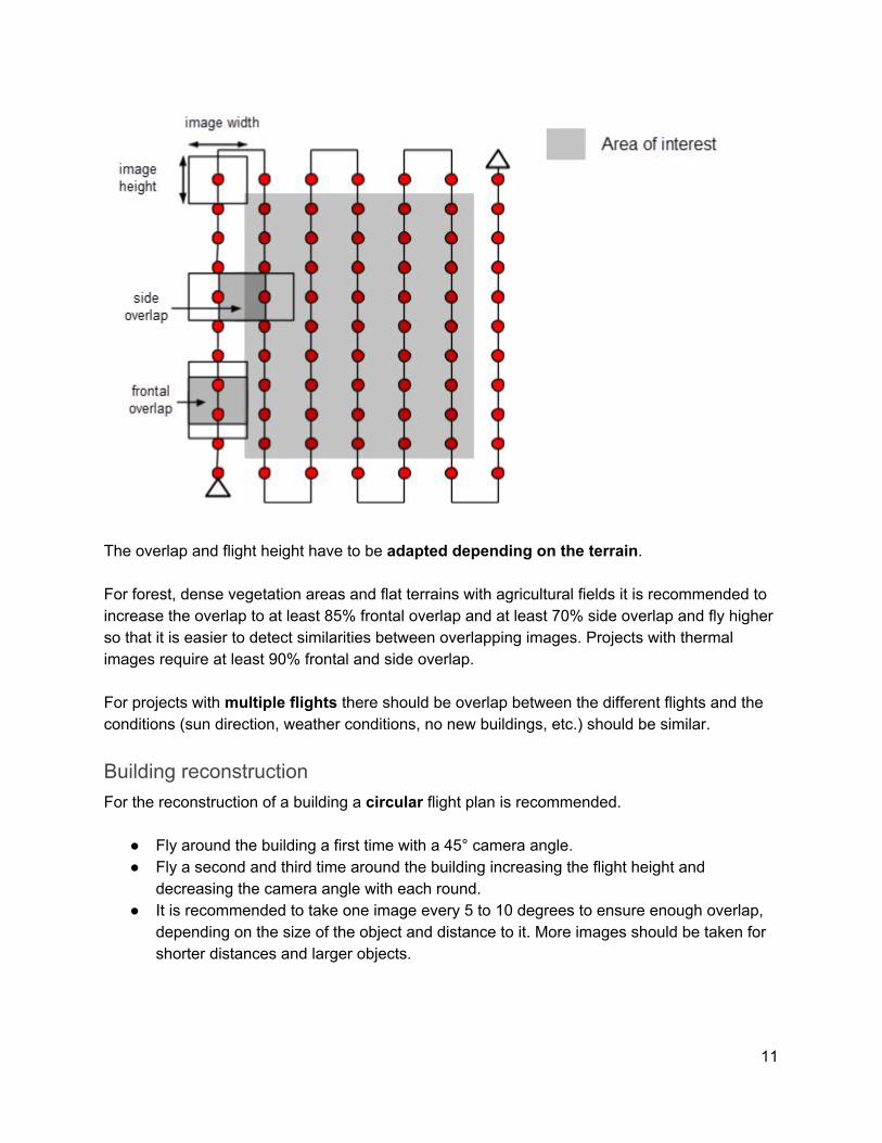
The overlap and flight height have to be adapted depending on the terrain. For forest, dense vegetation areas and flat terrains with agricultural fields it is recommended to increase the overlap to at least 85% frontal overlap and at least 70% side overlap and fly higher so that it is easier to detect similarities between overlapping images. Projects with thermal images require at least 90% frontal and side overlap. For projects with multiple flights there should be overlap between the different flights and the conditions (sun direction, weather conditions, no new buildings, etc.) should be similar.
Building reconstruction For the reconstruction of a building a circular flight plan is recommended.
● Fly around the building a first time with a 45° camera angle. ● Fly a second and third time around the building increasing the flight height and
decreasing the camera angle with each round. ● It is recommended to take one image every 5 to 10 degrees to ensure enough overlap,
depending on the size of the object and distance to it. More images should be taken for shorter distances and larger objects.
11
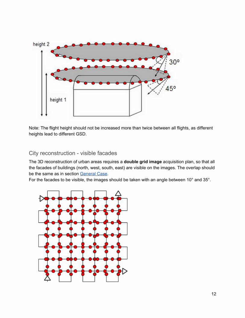
Note: The flight height should not be increased more than twice between all flights, as different heights lead to different GSD.
City reconstruction - visible facades The 3D reconstruction of urban areas requires a double grid image acquisition plan, so that all the facades of buildings (north, west, south, east) are visible on the images. The overlap should be the same as in section General Case. For the facades to be visible, the images should be taken with an angle between 10° and 35°.
12
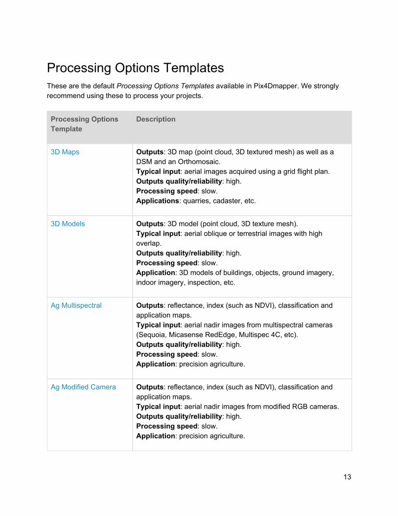
Processing Options Templates These are the default Processing Options Templates available in Pix4Dmapper. We strongly recommend using these to process your projects.
Processing Options Template
Description
3D Maps Outputs: 3D map (point cloud, 3D textured mesh) as well as a DSM and an Orthomosaic. Typical input: aerial images acquired using a grid flight plan. Outputs quality/reliability: high. Processing speed: slow. Applications: quarries, cadaster, etc.
3D Models Outputs: 3D model (point cloud, 3D texture mesh). Typical input: aerial oblique or terrestrial images with high overlap. Outputs quality/reliability: high. Processing speed: slow. Application: 3D models of buildings, objects, ground imagery, indoor imagery, inspection, etc.
Ag Multispectral Outputs: reflectance, index (such as NDVI), classification and application maps. Typical input: aerial nadir images from multispectral cameras (Sequoia, Micasense RedEdge, Multispec 4C, etc). Outputs quality/reliability: high. Processing speed: slow. Application: precision agriculture.
Ag Modified Camera Outputs: reflectance, index (such as NDVI), classification and application maps. Typical input: aerial nadir images from modified RGB cameras. Outputs quality/reliability: high. Processing speed: slow. Application: precision agriculture.
13
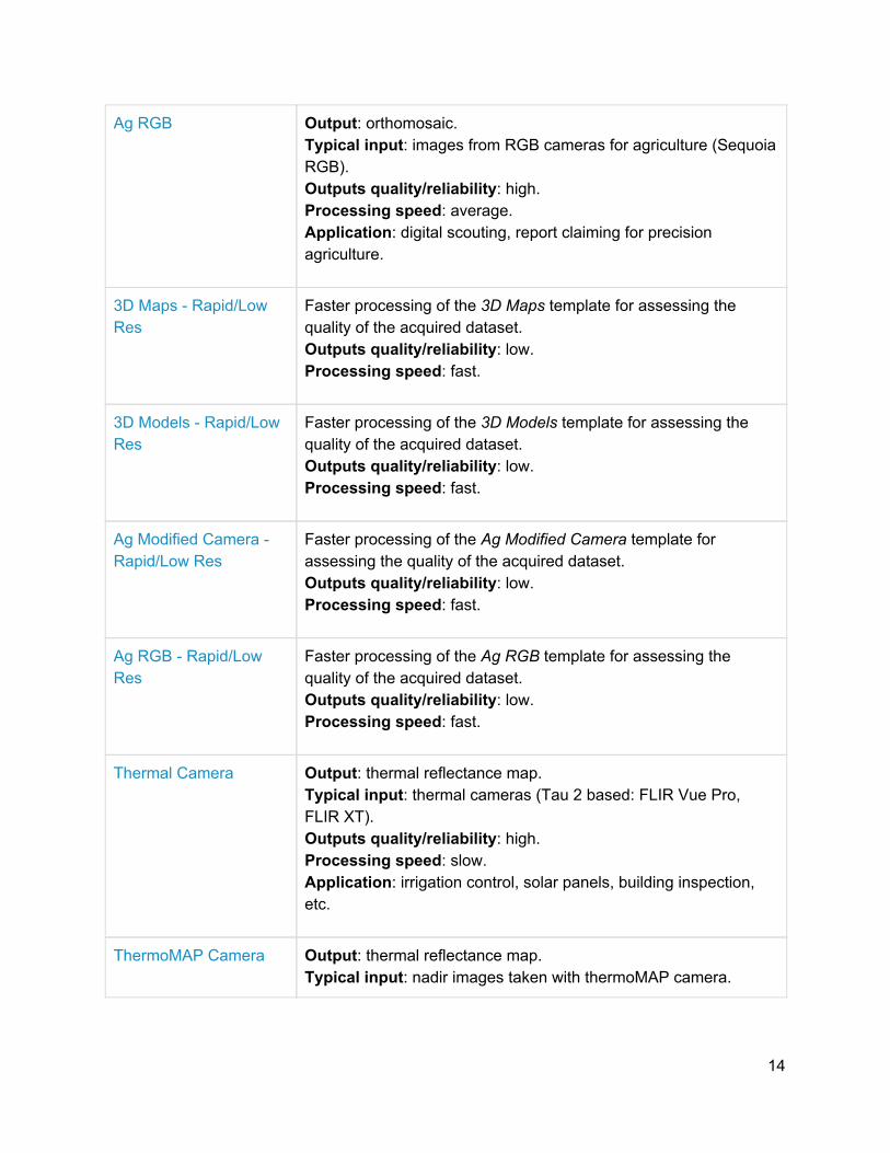
Ag RGB Output: orthomosaic. Typical input: images from RGB cameras for agriculture (Sequoia RGB). Outputs quality/reliability: high. Processing speed: average. Application: digital scouting, report claiming for precision agriculture.
3D Maps - Rapid/Low Res
Faster processing of the 3D Maps template for assessing the quality of the acquired dataset. Outputs quality/reliability: low. Processing speed: fast.
3D Models - Rapid/Low Res
Faster processing of the 3D Models template for assessing the quality of the acquired dataset. Outputs quality/reliability: low. Processing speed: fast.
Ag Modified Camera - Rapid/Low Res
Faster processing of the Ag Modified Camera template for assessing the quality of the acquired dataset. Outputs quality/reliability: low. Processing speed: fast.
Ag RGB - Rapid/Low Res
Faster processing of the Ag RGB template for assessing the quality of the acquired dataset. Outputs quality/reliability: low. Processing speed: fast.
Thermal Camera Output: thermal reflectance map. Typical input: thermal cameras (Tau 2 based: FLIR Vue Pro, FLIR XT). Outputs quality/reliability: high. Processing speed: slow. Application: irrigation control, solar panels, building inspection, etc.
ThermoMAP Camera Output: thermal reflectance map. Typical input: nadir images taken with thermoMAP camera.
14
Output quality/reliability: high. Processing speed: slow.
How to create a project This section goes step by step through the process of creating a new project. Example image datasets can be downloaded from the Pix4D Knowledge Base.
Creating a New Project To create a new project:
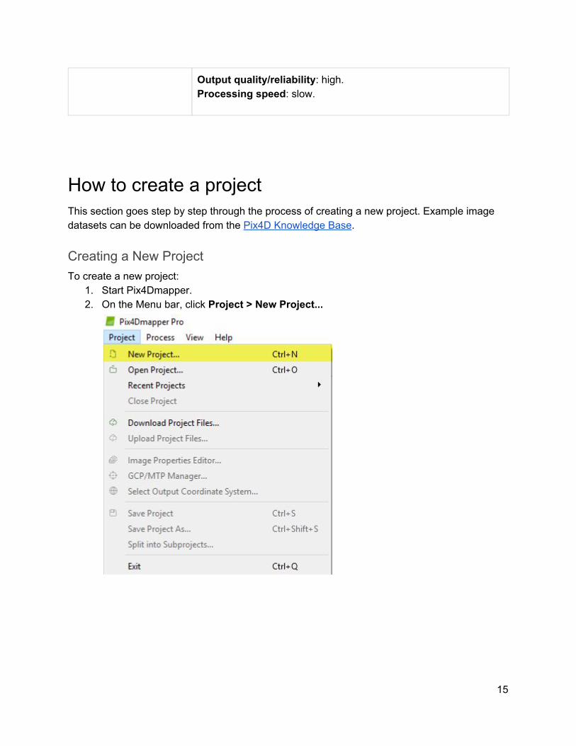
1. Start Pix4Dmapper. 2. On the Menu bar, click Project > New Project...
15
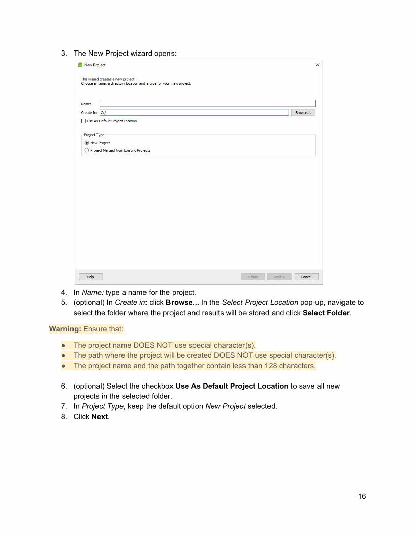
3. The New Project wizard opens:
4. In Name: type a name for the project. 5. (optional) In Create in: click Browse... In the Select Project Location pop-up, navigate to
select the folder where the project and results will be stored and click Select Folder.
Warning: Ensure that:
● The project name DOES NOT use special character(s). ● The path where the project will be created DOES NOT use special character(s). ● The project name and the path together contain less than 128 characters.
6. (optional) Select the checkbox Use As Default Project Location to save all new
projects in the selected folder. 7. In Project Type, keep the default option New Project selected. 8. Click Next.
16
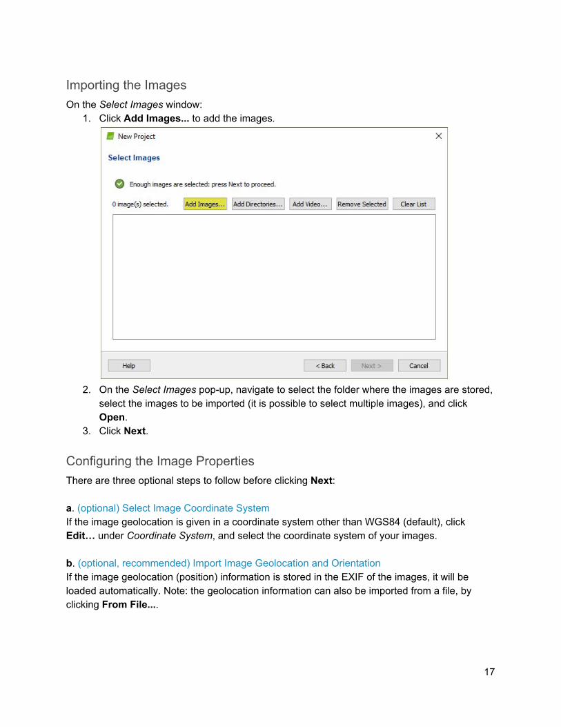
Importing the Images On the Select Images window:
1. Click Add Images... to add the images.
2. On the Select Images pop-up, navigate to select the folder where the images are stored,
select the images to be imported (it is possible to select multiple images), and click Open.
3. Click Next.
Configuring the Image Properties There are three optional steps to follow before clicking Next: a. (optional) Select Image Coordinate System If the image geolocation is given in a coordinate system other than WGS84 (default), click Edit… under Coordinate System, and select the coordinate system of your images. b. (optional, recommended) Import Image Geolocation and Orientation If the image geolocation (position) information is stored in the EXIF of the images, it will be loaded automatically. Note: the geolocation information can also be imported from a file, by clicking From File....
17
Note:
● The software considers the Date Taken field of the EXIF to set up the order in which the images are taken.
● Step 1. Initial Processing is faster for projects with image geolocation. In the case of not sufficient overlap, image geolocation helps to calibrate the images.
c. (optional) Edit Selected Camera Model A camera model needs to be defined in order to run a project in Pix4Dmapper. The parameters of this model depend on the camera that was used to capture the image. Most cameras save their name in the metadata of the image in EXIF format. This field is used to associate a given camera model to all the images captured with this camera. The Selected Camera Model section, on the Image Properties window, displays the selected camera model. The camera model can be:
○ Valid: A green check is displayed if the camera model is valid. A camera model is valid if it already exists in the camera model database of Pix4Dmapper or if there is sufficient information in the EXIF data of the images to create a new camera model that will be saved into the user camera model database. If the camera model is retrieved from the EXIF data, it is recommended to check the camera model parameters and, if needed, to edit them.
○ Invalid: A red cross is displayed if the camera model is not valid. A camera model is invalid if it is not in the camera model database of Pix4Dmapper and if there is not enough information in the EXIF data of the images. In this case, the camera model needs to be defined manually.
Selecting the Output / GCP Coordinate System In the Select Output Coordinate System window:
1. (optional) Change the Output / GCP Coordinate System.
Note:
● By default, the output and GCP coordinates system will be the same. Thereby, outputs can be shown in the coordinate system of the GCPs.
● By default, the Unit is m (meters). ● If the images have geolocation, by default, Auto detected is selected, displaying the
corresponding UTM or NAD83 zone of the images. ● If the images do not have geolocation, by default, Arbitrary Coordinate System is
selected.
18
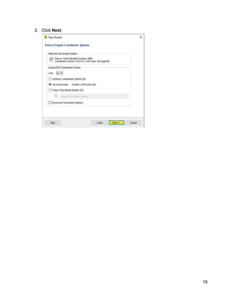
2. Click Next.
19
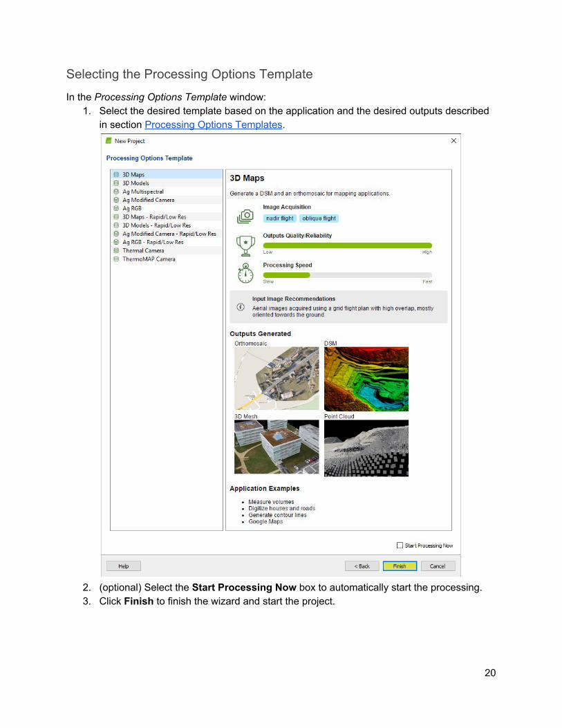
Selecting the Processing Options Template
Ιn the Processing Options Template window: 1. Select the desired template based on the application and the desired outputs described
in section Processing Options Templates.
2. (optional) Select the Start Processing Now box to automatically start the processing. 3. Click Finish to finish the wizard and start the project.
20
Processing Steps This section describes the three steps for processing with Pix4Dmapper.
1. Initial Processing In this step the images and additional inputs such as GCPs described in section Inputs will be used to do the following tasks:
● Keypoints extraction: Identify specific features as keypoints in the images. ● Keypoints matching: Find which images have the same keypoints and match them. ● Camera model optimization: Calibrate the internal (focal length,...) and external
parameters (orientation,...) of the camera. ● Geolocation GPS/GCP: Locate the model if geolocation information is provided.
Automatic Tie Points are created during this step. These are the basis for the next steps of processing. For more information about outputs, see section Outputs.
2. Point Cloud and Mesh This step will build on the Automatic Tie Points with:
● Point Densification: Additional Tie Points are created based on the Automatic Tie Points that results in a Densified Point Cloud.
● 3D Textured Mesh: Based on the Densified Point Cloud a 3D Textured Mesh can be created.
3. DSM, Orthomosaic and Index This step enables the creation of:
● Digital Surface Model (DSM): The creation of the DSM will enable the computation of Volumes, Orthomosaics and Reflectance Maps.
● Orthomosaic: The creation of the Orthomosaic is based on orthorectification. This method removes the perspective distortions from the images.
● Reflectance Map: The goal is to produce a map where the value of each pixel faithfully indicates the reflectance of the object.
● Index Map: Generate an Index Map where the color of each pixel is computed using a formula that combines different bands of the Reflectance Map(s).
21
Ground Control Points (GCPs) This method is used when the image geolocation and the GCPs are in a known coordinate system that can be selected from Pix4Dmapper's coordinate system database. The two systems do not need to be the same as. Pix4Dmapper is able to do the conversion between two known coordinate systems. This is the MOST COMMON CASE and makes it possible to mark the GCPs on the images with little manual intervention. However, this method is not suited for "overnight" processing during which the different processing steps start automatically in a row and do not require any supervision by the user.
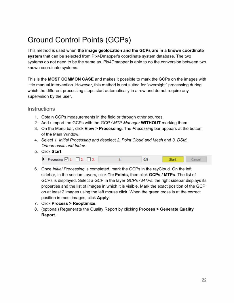
Instructions 1. Obtain GCPs measurements in the field or through other sources. 2. Add / Import the GCPs with the GCP / MTP Manager WITHOUT marking them. 3. On the Menu bar, click View > Processing. The Processing bar appears at the bottom
of the Main Window. 4. Select 1. Initial Processing and deselect 2. Point Cloud and Mesh and 3. DSM,
Orthomosaic and Index. 5. Click Start.
6. Once Initial Processing is completed, mark the GCPs in the rayCloud. On the left
sidebar, in the section Layers, click Tie Points, then click GCPs / MTPs. The list of GCPs is displayed. Select a GCP in the layer GCPs / MTPs: the right sidebar displays its properties and the list of images in which it is visible. Mark the exact position of the GCP on at least 2 images using the left mouse click. When the green cross is at the correct position in most images, click Apply.
7. Click Process > Reoptimize. 8. (optional) Regenerate the Quality Report by clicking Process > Generate Quality
Report.
22

www.pix4d.com
23


![imensional 5 econstruction of ctin in a 6 ensory lial ell ... MANUSCRIPTS pdfs/2011 Watanabe... · Bi-plane PALM [6] and several other techniques [7-9] have been developed to overcome](https://img.pdfslide.us/doc/110x75/5e786a8c78704d33342ba269/imensional-5-econstruction-of-ctin-in-a-6-ensory-lial-ell-manuscripts-pdfs2011.jpg)


![E VALUATE THE DEGREE TO WHICH THE C IVIL W AR AND R ECONSTRUCTION PROVED TO BE A TEST OF THE SUPREMACY OF THE NATIONAL GOVERNMENT. Week 3 Day 4 [second]](https://img.pdfslide.us/doc/110x75/56649f2a5503460f94c43cf3/e-valuate-the-degree-to-which-the-c-ivil-w-ar-and-r-econstruction-proved-to.jpg)