Embed Size (px)
Citation preview
Piston pump unit with reservoir for use in centralized lubrication systems
Product series:
KFA1-.., KFA10-..
KFAS1-.., KFAS10-..
Owner’s Manual - Containing Installation,
Operation and Maintenance Instructions (Original installation instructions in accordance with EC-
Machinery Directive 2006/42/EC)
Version 05
WARNING:
Read this owner's manual before installing, operating or maintaining the product. Failure to follow the
instructions and safety precautions in this owner’s manual could result in serious injury, death, or property
damage. Keep for future reference.

Masthead, Service Page 2 EN
Masthead This owner’s manual - containing installation,
operation and maintenance instructions complies
with EC-Machinery Directive 2006/42/EC and is an
integral part of the described product. It must be
kept for future use.
This owner’s manual - containing installation,
operation and maintenance instructions was created
in accordance with the valid standards and
regulations on documentation, VDI 4500 and EN
292.
© SKF Lubrication Systems Germany GmbH
This documentation is protected by copyright. The
photomechanical reproduction, copying, and distri-
bution of this documentation or parts thereof by
means of processes such as data processing, data
carriers, and data networks is strictly prohibited
without the express permission of SKF Lubrication
Systems Germany GmbH .
SKF Lubrication Systems Germany GmbH reserves
the right to make content and technical changes.
Service If you have technical questions, please contact the
following offices:
SKF Lubrication Systems Germany GmbH
Berlin Plant
Motzener Strasse 35/37
12277 Berlin
Germany
Tel. +49 (0)30 72002-0
Fax +49 (0)30 72002-111
Hockenheim Plant
2. Industriestrasse 4
68766 Hockenheim
Germany
Tel. +49 (0)62 05 27-0
Fax +49 (0)62 05 27-101
www.skf.com/lubrication

Table of contents Page 3 EN
Table of contents Owner’s Manual - Containing Installation,
Operation and Maintenance Instructions
(Original installation instructions in accordance with
EC-Machinery Directive 2006/42/EC)
Masthead ................................................................. 2
Service ..................................................................... 2
Table of contents .................................................... 3
Information concerning EC Declaration of
Incorporation .......................................................... 4
General information ............................................... 5
Explanation of symbols and signs ........................ 5
1. Safety instructions .......................................... 6
1.1. Intended use ................................................. 6
1.2. Authorized personnel ................................. 6
1.3. Electric shock hazard .................................. 7
1.4. System pressure hazard ............................ 7
1.5. Warranty and liability ................................. 7
2. Lubricants ........................................................ 8
2.1. General information .................................... 8
2.2. Selection of lubricants ................................ 8
2.3. Approved lubricants .................................... 9
2.4. Lubricants and the environment .............. 9
2.5. Lubricant hazards........................................ 9
3. Design and function ...................................... 10
3.1. Area of application and design................ 10
3.2. Pump elements.......................................... 12
3.3. Pressure regulating valve ........................ 13
3.4. Fill level monitoring................................... 14
3.4.1. Visual fill level monitoring .................... 14
3.4.2. Electrical fill level monitoring .............. 14
3.5. Electronic control unit (optional) ............ 14
3.5.1. Modes of operation ............................... 14
3.5.2. Contact time (pump cycle time) ......... 14
3.5.3. Interval time ........................................... 14
3.5.4. System monitoring ............................... 14
3.5.5. Progressive distributor monitoring ... 15
3.5.6. Block mode ............................................. 15
3.5.7. Fill level monitoring .............................. 15
3.5.8. Parameter memory .............................. 15
3.6. Piston pump units with progressive
distributor installed ................................... 15
4. Assembly instructions ................................... 16
4.1. General information ................................. 16
4.2. Setup and attachment ............................. 16
4.3. Connection dimensions ............................ 17
4.4. Electrical connection ................................. 18
4.4.1. Electric motor connection ................... 18
4.4.2. KFA1, KFA1-W (commercial vehicles)
.................................................................. 19
4.4.3. KFAS1, KFAS1-W (commercial
vehicles) .................................................. 20
4.4.4. KFA1-M, KFA1-M-W (industrial) ....... 21
4.4.5. KFAS1-M, KFAS1-M-W, KFAS1-M-Z,
KFAS1-M-W-Z (industrial) ................. 22
4.4.6. KFA10, KFA10-W (commercial
vehicles) .................................................. 24
4.4.7. KFAS10, KFAS10-W (industrial) ........ 25
4.5. Installation of pump elements ................ 27
4.6. Lubrication line connection ..................... 28
4.7. Lubrication line arrangement ................. 28
5. Transport, delivery, and storage ................. 31
5.1. Transport .................................................... 31
5.2. Delivery ....................................................... 31
5.3. Storage........................................................ 31
5.3.1. Storage of lubrication units ................ 31
5.3.2. Storage of electronic and electrical
devices ..................................................... 31
5.3.3. Storage - general information ............ 31
6. Operation ....................................................... 32
6.1. General information .................................. 32
6.2. Filling the lubricant reservoir .................. 32
6.3. Vent centralized lubrication system ....... 34
7. Electronic control unit .................................. 35
7.1. KFAS control unit (industrial and
commercial vehicles) ................................. 35
7.1.1. Display and control elements (KFAS) 35
7.1.2. Pushbutton operation (KFAS) ............. 36
7.1.3. Programming (KFAS) ............................ 39
7.1.4. Operation of KFAS (industrial and
commercial vehicles) ............................. 46
7.1.5. KFAS fault indications ........................... 49
8. Shutdown ....................................................... 50
8.1. Temporary shutdown ............................... 50
8.2. Permanent shutdown ............................... 50
9. Maintenance .................................................. 51
9.1. General notes ............................................. 51
9.2. Cleaning ....................................................... 51
9.3. Replacing the pump element .................. 51
10. Malfunctions .................................................. 53
10.1. Fault indications on piston pump units
without control unit ................................... 53
10.1.1. Piston pump units without fill level
monitoring (KFA..) .................................. 53
10.1.2. Piston pump units with integrated fill
level monitoring (KFA..-W) .................. 53
10.2. Fault analysis and rectification................ 53
11. Technical data ............................................... 55

Information concerning EC Declaration of Incorporation Page 4 EN
The product
piston pump unit with reservoir
of the series:
KFA1-.., KFA10-..
KFAS1-.., KFAS10-..
SKF herewith certifies that it conforms to the
pertinent safety requirements set forth in the
following Council Directive(s) for the harmonisation
of the laws of the Member States...
• Machinery Directive 2006/42/EC
• Electromagnetic Compatibility 2014/30/EU
• Electromagnetic Compatibility 2004/104/EC
• RoHS Directive 2011/65/EU
...
SKF further declares that the above mentioned
product is meant for integration into a machinery /
for connection to other machinery according to the
EC-Machinery Directive 2006/42/EC, Appendix II
Part B. Starting up the product is not permissible
until it is assured that the machinery, vehicle or the
like in which the product was installed meets the
provisions and requirements of the regulations set
forth in the EC Directive 2006/42/EC.
Notes:
(a) This declaration certifies conformity with the
aforementioned directive(s), but does not
contain any assurance of properties.
(b) The safety instructions in the owner’s manual must be observed.
(c) The certified product must not be started up
until it is confirmed that the equipment, ma-
chinery, vehicle or the like in which the product
was installed meets the provisions and re-
quirements of the national directives to be ap-
plied. This is in particular important for the
implementation of the Use of Work Directive.
(d) Operation of the products on non-standard
main voltage as well as nonobservance of in-
stallation instructions can affect the EMC
properties and electrical safety.
(a)
Notes on the Low Voltage Directive 2014/35/EU
The protective regulations of the Low Voltage
Directive 2014/35/EU are fulfilled according to
annex I (1.5.1) of Machinery Directive 2006/42/EC.
Notes on the Pressure Equipment Directive
2014/68/EU
Due to its performance characteristics, the product
does not reach the limit values defined in Article 4,
Paragraph 1, Subparagraph (a) item (i) and is,
pursuant to Article 4, Paragraph 3, excluded from
the scope of Pressure Equipment Directive
2014/68/EU.
The EC Declaration of Incorporation is part of the
product documentation. This document is delivered
with the product.
Information concerning EC Declaration of Incorporation

General information Page 5 EN
General information Explanation of symbols and signs
You will find these symbols, which warn of specific
dangers to persons, material assets, or the
environment, next to all safety instructions in these
owner’s manual.
Please heed these instructions and proceed with
special care in such cases. Please pass all safety
instructions to other users.
Instructions attached directly to the equipment, such
as rotational direction arrows and fluid connection
labels, must be followed. Replace such signs if they
become illegible.
o Rotational direction arrow
o Fluid connection label
Read this Owner's Manual before installing, oper-
ating or maintaining the product. Failure to follow
the instructions and safety precautions in this
owner’s manual could result in serious injury, death,
or property damage. Keep for future reference.
Note: Not every symbol and corresponding infor-
mation described in the Safety Information is used
in this owner’s manual.
Table 3 Informational symbols
Symbol Meaning
Note
• Prompts an action
o Bullet list items
Refers to other facts, causes or
consequences
Provides additional information
Table of 1 Hazard symbols
Symbol Standard Meaning
DIN 4844-2 W000 General hazard
DIN 4844-2 W008 Voltage
DIN 4844-2 W026 Slip hazard
DIN 4844-2 W028 Hot surface
Table 2 Safety signal words and their
meaning
Signal word Meaning
Danger! Danger of bodily injury
Warning! Danger of damage to property or the
environment
Note Additional information

1. Safety instructions Page 6 EN
1. Safety instructions The operator of the described product
must ensure that the owner’s manual are
read and understood by all persons tasked
with the assembly, operation,
maintenance, and repair of the product.
The owner’s manual must be kept readily
available.
Note that the owner’s manual form part of
the product and must accompany the
product if sold to a new owner.
The described product is manufactured in
accordance with the generally accepted rules and
standards of industry practice and with occupational
safety and accident prevention regulations. Risks
may, however, arise from its usage and may result
in physical harm to persons or damage to other
material assets. Therefore the
product may only be used in proper technical
condition and in observance of the owner’s manual. In particular, any malfunctions which may affect
safety must be remedied immediately.
In addition to the owner’s manual, statutory regulations and other general
regulations for accident prevention and
environmental protection must be
observed and applied.
1.1. Intended use
All products from SKF Lubrication Systems
Germany GmbH may be used only for
their intended purpose and in accordance
with the information in the product's
owner’s manual.
The described product is for supplying centralized
lubrication systems with lubricant and is intended
for use in centralized lubrication systems. Any other
use of this product constitutes improper use.
Hazardous materials of any kind, especially the
materials classified as hazardous by CLP Regulation
EC 1272/2008 may only be used to fill SKF
centralized lubrication systems and components and
deliv-ered and/or distributed with the same after
consulting with and receiving written approval from
SKF.
None of the products manufactured by SKF
Lubrication Systems Germany GmbH can be used
with gases, liquefied gases, gases dissolved under
pressure, steams or fluids that will reach a steam
pressure of more than 0.5 bar above the normal
atmospheric pressure (1013 mbar) in the permis-
sible application temperature range.
Unless specially indicated otherwise, products from
SKF Lubrication Systems Germany GmbH are not
approved for use in potentially explosive areas as
defined in the ATEX Directive 94/9/EC.
1.2. Authorized personnel
The products described in the installation instruc-
tions may only be installed, operated, maintained,
and repaired by qualified experts. Qualified experts
are persons who have been trained, instructed, and
familiarized with the end product into which the
described product is installed. These persons are
considered capable of such tasks due to their
education, training, and experience with valid
standards, conditions, accident prevention regula-
tions, and installation measures. They should be
able to carry out the required tasks and to recognize
- and thus avoid - any dangers that might otherwise
occur.
A definition of what constitutes a qualified person
and who are unqualified persons are stipulated in
DIN VDE 0105 and IEC 364.

1. Safety instructions Page 7 EN
1.3. Electric shock hazard
Electrical connections for the described product may
only be established by qualified and trained
personnel authorized to do so by the operator, and
in observance of the local conditions for connections
and local regulations (e.g., DIN, VDE). Serious injury
or death and property damage may result from
improperly connected products.
Danger!
Performing work on an energized pump or
product may result in serious injury or
death. Assembly, maintenance, and repair
work may only be performed on products
that have been de-energized by qualified
technical personnel. The supply voltage
must be switched off before opening any of
the product's components.
1.4. System pressure hazard
Danger!
Centralized lubrication systems are
pressurized during operation. Centralized
lubrication systems must therefore be
depressurized before starting assembly,
maintenance or repair work, or any system
modifications or system repairs.
1.5. Warranty and liability
SKF Lubrication Systems Germany GmbH assumes
no warranty or liability for the following:
o Non-compliant usage
o Improper assembly/disassembly or improper
operation
o Use of unsuitable or contaminated lubricants
o Maintenance and repair work performed
improperly or not performed at all
o Use of non-original SKF spare parts
o Alterations or modifications performed without
written approval from SKF Lubrication Systems
Germany GmbH
o Non-compliance with the instructions for
transport and storage

2. Lubricants Page 8 EN
2. Lubricants 2.1. General information
All products from SKF Lubrication Systems
Germany GmbH may be used only for
their intended purpose and in accordance
with the information in the product's
owner’s manual.
Intended use is the use of the products for the
purpose of providing centralized
lubrication/lubrication of bearings and friction points
using lubricants within the physical usage limits
which can be found in the documentation for the
product, e.g. owner’s manual/operating instructions
and the product descriptions, e.g. technical drawings
and catalogs.
Particular attention is called to the fact that
hazardous materials of any kind, especially those
materials classified as hazardous by EC Directive
67/548/EEC, Article 2, Para. 2, may only be filled
into centralized lubrication systems and components
and delivered and/or distributed with such systems
and components after consulting with and obtaining
written approval from SKF Lubrication Systems
Germany GmbH .
No products manufactured by SKF Lubrication
Systems Germany GmbH are approved for use in
conjunction with gases, liquefied gases, pressurized
gases in solution, vapors, or such fluids whose vapor
pressure exceeds normal atmospheric pressure
(1013 mbar) by more than 0.5 bar at their
maximum permissible temperature.
Other media which are neither lubricant nor
hazardous substance may only be fed after
consulting with and obtaining written approval from
SKF Lubrication Systems Germany GmbH .
SKF Lubrication Systems Germany GmbH considers
lubricants to be a component of the system design
and must be factored into the selection of
components and the design of centralized
lubrication systems. The lubricating properties of the
lubricants are critically important in making these
selections.
2.2. Selection of lubricants
Warning!
The amount of lubricant required at a
lubrication point is specified by the bearing
or machine manufacturer. It must be
ensured that that the required quantity of
lubricant is provided to the lubrication
point. The lubrication point may otherwise
not receive adequate lubrication, which can
lead to damage and failure of the bearing.
Observe the instructions from the machine
manufacturer regarding the lubricants that
are to be used.
The selection of a lubricant suitable for the
lubrication task is made by the machine/system
manufacturer and/or the operator of the
machine/system in cooperation with the lubricant
supplier. When selecting a lubricant, the type of
bearing/friction point, the expected load during
operation, and the anticipated ambient conditions
must be taken into account. All economic and
ecologial aspects must also be considered.
If required, SKF Lubrication Systems
Germany GmbH can help customers to
select suitable components for the
conveyance of the selected lubricant and to
plan and design their centralized
lubrication system.
Please contact SKF Lubrication Systems Germany
GmbH if you have further questions regarding
lubricants. Lubricants can be tested in the
company's laboratory for their suitability for
pumping in centralized lubrication systems (e.g.,
"bleeding").
You can request an overview of the lubricant tests
offered by SKF Lubrication Systems Germany GmbH
from the company's Service department.

2. Lubricants Page 9 EN
2.3. Approved lubricants
Warning!
Only lubricants approved for the product
may be used. Unapproved lubricants that
are unsuitable can lead to failure of the
product and damage to property.
Warning!
Different lubricants must not be mixed
together. Doing so can cause damage and
require extensive cleaning of the
product/centralized lubrication system. It is
recommended that an indication of the
lubricant in use be attached to the
lubricant reservoir in order to prevent
accidental mixing of lubricants.
The described product can be operated using
lubricants that meet the specifications in the
technical data.
Note that in rare cases, there may be lubricants
whose properties are within the permissible limits
values but whose other characteristics render them
unsuitable for use in centralized lubrication systems.
For example, synthetic lubricants may be
incompatible with elastomers.
2.4. Lubricants and the environment
Warning!
Lubricants can contaminate soil and bodies
of water. Lubricants must be used and
disposed of properly. Observe the local
regulations and laws regarding the
disposal of lubricants.
It is important to note that lubricants are
environmentally hazardous, flammable substances
that require special precautionary measures during
transport, storage, and processing. Consult the
safety data sheet from the lubricant manufacturer
for information regarding transport, storage,
processing, and environmental hazards of the
lubricant that will be used. The safety data sheet for
a lubricant can be requested from the lubricant
manufacturer.
2.5. Lubricant hazards
Danger!
Centralized lubrication systems must
always be free of leaks. Leaking lubricant is
hazardous due to the risk of slipping and
injury. Beware of any lubricant leaking out
during assembly, operation, maintenance,
or repair of centralized lubrication systems.
Leaks must be sealed without delay.
Lubricant leaking from centralized lubrication
systems is a serious hazard. Leaking lubricant can
create risks that may result in physical harm to
persons or damage to other material assets.
Follow the safety instructions on the
lubricant's safety data sheet.
Lubricants are hazardous substances. The safety
instructions on the lubricant's safety data sheet
must be strictly followed. The safety data sheet for a
lubricant can be requested from the lubricant
manufacturer.

3. Design and function Page 10 EN
3. Design and function 3.1. Area of application and design
The piston pump units with reservoir described here
are characterized by their their compact
construction. Depending on the model design, they
are suitable for supplying lubricant to centralized
lubrication systems with progressive distributors on
machines, systems or vehicles ( Table4). Piston
pump units with reservoir deliver greases up to
NLGI Grade 2.
Piston pump units with reservoir differ in the way
they can be electrically connected as well as in the
control and monitoring of functions. Up to two
independent zones can be operated by installing a
maximum of two pump elements.
The standard design of piston pump units with
reservoir consist of a pump housing and a lubricant
reservoir.
The lubricant reservoir is made of plastic and is
equipped with a spring-loaded follower piston.
The pump housing contains the electric motor, the
mechanics for driving the pump elements and,
depending on the model design, the control unit. All
other functional and connection elements are
arranged on the pump housing.
Table 4 Model designs
Application Description Monitoring Control Mounted
manifold Fill level Cycle switch External Internal
Commercial
vehicles
12 V / 24 V DC
KFA1 - - • - -
KFA1-W • - • - -
KFAS1 - - - • -
KFAS1-W • - - • -
KFAS1-W-3 (4, …9) • - - • •
Industrial
24 V DC
KFA1-M - - • - -
KFA1-M-W • - • - -
KFAS1-M - - - • -
KFAS1-M-Z - • - • -
KFAS1-M-W • - - • -
KFAS1-M-W-Z • • - • -
Industrial
115 V / 230 V AC
KFA10 - - • - -
KFA10-W • - • - -
KFAS10 - - • -
KFAS10-W • - - • -
KFAS10-W-3 (4, …9) • - - • •

3. Design and function Page 11 EN
KFA1 KFAS1
1
2
4
5
6
998 8
4
5
6
7
3
Fig. 1. Piston pump units with reservoir, series KFA1 and KFAS1
1 Lubricant reservoir 4 Lubricant outlet 1 7 Control screen
2 Pump housing 5 Filler socket 8 Mounting flange
3 Pressure regulating valve 6 Lubricant outlet 2 (with pump element on KFAS1) 9 Electrical connections

3. Design and function Page 12 EN
3.2. Pump elements
Piston pump units with reservoir possess two
lubricant outlets that can be equipped with a pump
element. Unused pump outlets must be closed using
a screw plug.
The pump elements meter the lubricant then feed it
into the main lubricant line of the centralized
lubrication system.
Model designs with progressive distributors (3- to
9-port) mounted on the pump housing feed the
lubricant directly into the progressive distributor.
The lubricant is then transported from the feeder's
outlets directly to the lubrication points.
The pump elements are designed for different
delivery rates depending on the lubrication task. The
different designs are indicated by grooves on the
wrench flat ( Table5).
For additional details about the pump elements, see
the associated documentation.
If no documentation is available, you can
request the documentation directly from
SKF Lubrication Systems Germany GmbH .
1
Fig.2. Pump element with O-ring (item 1)
Table 5. Available pump elements
Order No. Delivery rate in
cm3/min 1)
Number of
grooves
KFA1.U1 2,0 1
KFA1.U2 1,5 2
KFA1.U3 1,0 3 1) Output of NLGI Grade 2 grease at a temperature of 20 ℃
and back pressure of 50 bar

3. Design and function Page 13 EN
3.3. Pressure regulating valve
Danger!
Piston pump units with reservoir must only
be operated with the pressure control
valve installed. Non-observance may result
in severe injury or death and damage to
property due to overpressure.
The pressure control valve prevents excessive
pressure in the entire lubrication system. It is
mounted directly on the lubricant outlet. If the
system pressure exceeds the cracking pressure of
the pressure regulating valve, the valve opens and
lubricant escapes at the valve.
For additional details about the pressure relief valve,
see the associated documentation.
If no documentation is available, you can
request the documentation directly from
SKF Lubrication Systems Germany GmbH .
Table 6. Pressure regulating valves
Order No. Pipe in mm Cracking
pressure in bar
161-210-012 6 300 20
Table 7. Pressure regulating valves with T
connector
Order No. Pipe in mm Cracking
pressure in bar
161-210-016 10 300 20
161-210-030 10 200 20
161-210-031 8 200 20
161-210-032 6 200 20
161-210-040 10 120 5
161-210-041 8 120 5
161-210-042 6 120 5
A
P
R
M14x1,5
Fig.3. Pressure regulating valve
A Connection for lubricant line
P Pipe thread for pump element
R Lubricant leakage on malfunction
M14
x1,5
R
A
Fig.4. Pressure regulating valve with
T connector
A Connection for lubricant line
R Lubricant leakage on malfunction
P

3. Design and function Page 14 EN
3.4. Fill level monitoring
3.4.1. Visual fill level monitoring
Danger!
The lubricant reservoir fill level must be
checked regularly on piston pump units
with reservoir that are not equipped with
electrical fill level monitoring. Proper
lubrication is no longer guaranteed if the
fill level falls below the "min." mark, which
can result in severe injury or death and
property damage.
The entire centralized lubrication system
must be vented if the lubricant reservoir fill
level has fallen below the "min." mark.
The lubricant reservoir is transparent and has
marks indicating the maximum and minimum fill
level. The current level can be seen from the
position of the follower piston.
3.4.2. Electrical fill level monitoring
Piston pump units with reservoir can optionally be
equipped with a fill level switch. When the fill level in
the lubricant reservoir reaches the "min." mark, one
of the following occurs depending on the model
design:
o On piston pump units with integrated control
unit, the operational sequence is stopped and a
fault message appears on the control screen.
o On piston pump units without control unit, the
signal is issued via the corresponding connector.
3.5. Electronic control unit (optional)
Depending on the model design, the piston pump
units with reservoir may be equipped with a
programmable electronic control unit that controls
and monitors the lubrication procedure.
3.5.1. Modes of operation
Piston pump units with reservoir can be operated in
different modes. The units always operate cyclically,
i.e. a lubrication procedure (contact time) during
which the piston pump runs and supplies the
lubrication points is followed by a lubrication pause
(interval time). One lubrication cycle consists of a
contact time and an interval time.
Timer mode
The contact time and interval time are timer-
controlled.
PAUSE: Values in hours
CONTACT: Values in minutes
Counter mode (only KFAS)
The contact time is timer-controlled. The interval
time depends on the number of pulses, i.e. the
interval lasts until the control unit receives an
adjustable number of pulses from an external pulse
generator.
Connect an external pulse generator to
input DK/MK.
PAUSE: Values in pulses
CONTACT: Values in minutes
3.5.2. Contact time (pump cycle time)
The duration of the contact time is programmable.
With progressive distributor monitoring deactivated,
the duration of the lubrication procedure
corresponds to the set contact time.
3.5.3. Interval time
The duration of the interval time is programmable.
3.5.4. System monitoring
The system monitoring function is optional and
includes monitoring of:
o A fill level switch (if present) and/or
o One or two progressive distributors by one or
two cycle switches, respectively
Progressive distributor monitoring can be activated
and deactivated.
The monitoring of the fill level switch, if present,
always remains active.

3. Design and function Page 15 EN
In case of a fault, e.g. insufficient fill level, a fault
message is generated and the operational sequence
is stopped. The cause of the malfunction can be
shown on the control unit's screen. In addition, the
fault hours figure is stored and can also be
displayed.
3.5.5. Progressive distributor monitoring
The progressive distributor monitoring capabilities
differ on the KFAS and KFAS1-B series as follows:
KFAS
o Progressive distributor monitoring using one
cycle switch
o Number of edges for cycle switch is not
adjustable
With each piston stroke of the corresponding
progressive distributor, the cycle switches generate
a switching edge, which is registered by the control
unit and used to control the contact time. The
number of switching edges (stroke number)
required to limit the contact time can be set on the
control unit. Two switching edges are required for
one revolution of the progressive distributor.
3.5.6. Block mode
When progressive distributor monitoring is active,
the duration of the lubrication procedure
corresponds at least to the set contact time, though
the programmed number of switching edges for the
cycle switch(es) must also be attained. If the
required number of switching edges for the cycle
switch(es) is not attained during the contact time, an
additional contact time is started after a defined
delay. This process can be repeated up to three
times. This process is also referred to as block
operation, as the piston pump starts and stops
quickly several times.
Block operation is interrupted as soon as the set
number of piston detector signals has been received.
The length of an interval time following a successful
block operation is not changed. Operation continues
as normal. If the required number of switching
edges for the cycle switch(es) is not attained during
block operation, a fault message is issued.
3.5.7. Fill level monitoring
On units with fill level switch, the fill level is
monitored by the control unit. As soon as the fill
level of the lubricant reservoir falls below the
minimum, the control unit stops the operational
sequence of the centralized lubrication system and
issues a fault message.
If fill level monitoring is installed, it is always active.
3.5.8. Parameter memory
All essential system parameters are stored in the
control unit's non-volatile memory, ensuring that no
data is lost even in case of power failure or a
completely.
3.6. Piston pump units with
progressive distributor installed
Piston pump units of the KFA(S) series can
optionally be equipped with a progressive
distributor. The progressive distributor is mounted
at the base of the pump housing. The number of
lubricant connections on the mounted progressive
distributor is variable and must be specified when
ordering.

4. Assembly instructions Page 16 EN
4. Assembly instructions 4.1. General information
Only qualified technical personnel may install,
operate, maintain, and repair the piston pump units
described in the assembly instructions. Qualified
technical personnel are persons who have been
trained, assigned and instructed by the operator of
the final product into which the described piston
pump units are incorporated. Such persons are
familiar with the relevant standards, rules, accident
prevention regulations, and operating conditions as
a result of their training, experience, and instruction.
They are qualified to carry out the required activities
and in doing so recognize and avoid potential
hazards.
The definition of qualified personnel and the
prohibition against employing non-qualified
personnel are laid down in DIN VDE 0105 and IEC
364.
Before assembling/setting up the piston pump unit
with reservoir, the packaging material and any
shipping braces (e.g., plugs) must be removed. Keep
the packaging material until any discrepancies have
been resolved.
Warning!
The product must not be tilted or dropped.
During all assembly work on commercial vehicles or
machinery, observe the local accident prevention
regulations as well as the applicable operating and
maintenance specifications.
4.2. Setup and attachment
The piston pump unit with reservoir should be
protected from humidity and vibration, and should
be mounted so that it is easily accessible, allowing all
further installation work to be done without
difficulty. The control screen, if present, must be
easily visible and reachable.
Ensure that there is sufficient air circulation to
prevent excessive heating of the piston pump unit
with reservoir. For the maximum permissible
ambient temperature, see "Technical data."
For the product-specific technical data on
a specific piston pump unit with reservoir,
see the relevant documentation. If no
documentation is available, you can
request the documentation directly from
SKF Lubrication Systems Germany GmbH .
The mounting position of the piston pump unit with
reservoir is vertical as shown in the
documentation.
Drill the assembly holes for wall-mounting the
piston pump unit as specified in Chapter 4.3,
"Connection dimensions."

4. Assembly instructions Page 17 EN
Warning!
During assembly and especially when
drilling, always pay attention to the
following:
o Existing supply lines must not be
damaged by assembly work.
o Other units must not be damaged by
assembly work.
o The piston pump unit must not be
installed within range of moving parts.
o The piston pump unit must be installed
at an adequate distance from sources
of heat.
o Maintain safety clearances and comply
with local regulations for assembly and
accident prevention.
o Use existing holes on the vehicle frame
or other vehicle parts.
o Bridge large holes using body washers.
o Pay attention to steering lock angle,
spring action and possible wearing
spots during assembly.
Warning!
The German Ordinance on the National
and International Carriage of Dangerous
Goods by Road, Rail and Inland Waterways
(GGVSEB) must be observed for tankers
and other vehicles that transport
hazardous goods.
Warning!
Any change to a commercial vehicle,
especially the installation of additional
equipment such as centralized lubrication
systems, must be checked and approved
by the competent technical authorities in
the operator country. Non-observance can
void the license to operate the commercial
vehicle.
4.3. Connection dimensions
Piston pump units with reservoir are designed for
wall mounting (industrial design) or installation on a
vehicle (commercial vehicle design). The piston
pump unit with reservoir is mounted on a
connecting flange with three fastening points. It is
fastened using three M8 screws, washers and self-
locking nuts. The tightening torque is 16 Nm.
For the dimensions and location of the fastening
holes, see the documentation of the piston pump
unit with reservoir. If no documentation is available,
the dimensions and location of the fastening holes
on the connecting flange can be determined by
taking measurements.
If no documentation is available, you can
request the documentation directly from
SKF Lubrication Systems Germany GmbH .

4. Assembly instructions Page 18 EN
4.4. Electrical connection
4.4.1. Electric motor connection
Piston pump units with reservoir are driven by
electric motors.
The general conditions for connections are given in
Table 8.
Danger!
Electrical connections for the piston pump
unit with reservoir may only be established
by qualified and trained personnel
authorized to do so by the operator, and in
observance of the local conditions for
connections and local regulations (e.g.,
DIN, VDE). Incorrectly connected piston
pump units with reservoir can cause
considerable damage to property and
result in serious injury or death.
Danger!
The mains voltage (supply voltage) must
match the specifications on the rating
plate of the piston pump unit. Check the
fuse protection of the electrical circuit. Use
only fuses with the prescribed amperage,
else bodily injury and property damage
may result.
Table 8 General conditions for connections
Design Rated voltage Typical power consumption
(load-dependent) 1)
Starting current
(approx. 20 ms) /
Inrush current 3.)
Back-up fuse
KFA1... / KFAS1...
Commercial vehicles
Mode S3 20%,
50 min
24 V DC
12 V DC
0.5 A
1.0 A
approx. 1.4 A
approx. 2.8 A
3.0 A
3.0 A
KFA1-M... / KFAS1-M...
Industrial
Mode S3 20%,
50 min
24 V DC 2) 0.5 A approx. 1.4 A 3.0 A
KFA10 / KFA10-W
Industrial
Mode S3 5%,
100 min
230 V/50 Hz
230 V/60 Hz
115 V/50 Hz
115 V/60 Hz
0.77 A
0.54 A
1.54 A
1.08 A
-
-
-
-
3.0 A
3.0 A
3.0 A
3.0 A
KFAS10 / KFAS10-W
Industrial
Mode S3 20%,
50 min
230 V 50/60 Hz
115 V 50/60 Hz
0.40 A
0.65 A
40 A
20 A
2.5 A
2.5 A
2.5 A
2.5 A 1) Typical value at an ambient temperature = 20 ℃ and operating pressure = 300 bar 2) Protective measures to be taken for operation according to intended use:
"Functional Extra Low Voltage" / "Protective Extra Low Voltage" (PELV) 3) only model design KFAS10-… with switch-mode power supply

4. Assembly instructions Page 19 EN
4.4.2. KFA1, KFA1-W (commercial vehicles)
Supply voltage 12/24 V DC
For voltage specifications, see the
rating plate of the piston pump unit and
Table 8.
The electrical connection of the piston pump units is
established via a 4-pin circular connector according
to DIN 72585-A1-4.1-Ag/K1.
Fig.5. Circular connector
Table 9. X1 4-pin circular connector
X1 PIN Color abbreviation Color coding
1 RD-BK Red-black
2 BN Brown
3 BK Black
4 PK Pink
KFA1 without fill level monitoring
Table 10. Cable set
Order No. Length of corrugated
hose
Length of
wires
997-000-820 10 m 12 m
KFA1M
X1 1 2 3 4
5) 5)
RD
-BK
BN
1)
F 3 A
15 31 Fig.6. Electrical connection of KFA1
1) External control unit;
relay contact "Pump ON"
5) PIN without internal connection
F Fuse
See Table9 for color coding.
KFA1-W with fill level monitoring
Table 11. Cable set
Order No. Length of corrugated
hose
Length of
wires
997-000-706 10 m 12 m
KFA1-WM
X1 1 2 3 4
RD
-BK
BN
BK
PK
1)
F 3 A
15 31 4)
max.
0,5 A
Q
WS
Fig.7. Electrical connection of KFA1-W
WS Integrated fill level switch
Contact position shown: "filled reservoir",
i.e. the fill level switch opens when the
lubricant quantity is insufficient
4) Evaluation of fill level switch signal
See Table9 for color coding.

4. Assembly instructions Page 20 EN
4.4.3. KFAS1, KFAS1-W (commercial
vehicles)
Supply voltage 12/24 V DC
For voltage specifications, see the
rating plate of the piston pump unit and
Table 8.
The electrical connection is established via a 7-pin
circular connector (AMP type).
Fig.8. Circular connector
Table 12. X1 7-pin circular connector
X1 PIN Color abbreviation Color coding
1 BN Brown
2 RD-BK Red-black
3 BU Blue
4 PK Pink
5 YE Yellow
6 BK Black
7 VT-GN Purple-green
KFAS1/KFAS1-W
without cycle switch monitoring
PINS 5 and 6 have no function. Do not bridge! The
following monitoring setting must be active in
programming mode: COP = OFF (factory setting).
With cycle switch monitoring
Connect the external cycle switch to PINs 5 and 6.
The following monitoring setting must be activated
in programming mode: COP = CS
( Chapter 7.1.3.3, "Set monitoring functions
(KFAS)").
KFAS1
No internal fill level monitoring
KFAS1-W
With internal fill level monitoring
If fill level monitoring is installed, it is always active.
If the fill level falls below the "min." mark, the
operational sequence is stopped and a fault
message appears on the screen.
The electrical connection details are identical with
those of the KFAS1 piston pump unit.
Table 13. Cable sets
Order No. Length of corrugated
hose
Length of
wires
997-000-630 12 m 12.2 m
997-000-650 16 m 16.2 m
Fig.9. Electrical connection of KFAS1 and
KFAS1-W
15 + Supply voltage potential
(ignition switch ON)
31 - Supply voltage potential
(0 V, GND)
DK External pushbutton
"Interim lubrication"
ZS External cycle switch
SL1 Signal lamp "Pump ON"
SL2 Signal lamp "Fault"
F Fuse
See Table12 for color coding.

4. Assembly instructions Page 21 EN
4.4.4. KFA1-M, KFA1-M-W (industrial)
Supply voltage 24 V DC
For voltage specifications, see the
rating plate of the piston pump unit and
Table 8.
X1 Electrical connection: Plug connector acc.
to DIN 175301-803.
X2 Signal output from fill level switch WS; M12x1
circular connector.
Plug
Fig.10. KFA1-M-W plug connector
KFA1-M without fill level monitoring
The piston pump unit possesses an X1 plug
connector.
1)
F 3 A
L+
24 V DC
M (OV, GND)
M
1
2
3
X1 1 2 3
5) 5)
KFA1-M
KFA1-M-W
Fig.11. X1 plug connector
1) External control unit;
relay contact "Pump ON"
5) PIN without internal connection
L+ + Supply voltage potential
(main machine switch ON)
M - Supply voltage potential
KFA1-M-W with fill level monitoring
The piston pump unit possesses an X1 and X2 plug
connector.
X2 1 2 3 4
BN
WH
BU
BK
+ MIN 5) OK
24 V DC, max. 0,5 A
Q
WS
KFA1-M-W
1 2
4 3
Fig.12. X2 circular connector
WS Integrated fill level switch
Contact position shown: "filled reservoir",
i.e. contacts 1-4 open when the lubricant
quantity is insufficient
Table 14. Color coding
X2 PIN Color abbreviation Color coding
1 BN Brown
2 WH White
3 BU Blue
4 BK Black
X2
Connecto
r

4. Assembly instructions Page 22 EN
4.4.5. KFAS1-M, KFAS1-M-W, KFAS1-M-Z,
KFAS1-M-W-Z (industrial)
Supply voltage 24 V DC
For voltage specifications, see the
rating plate of the piston pump unit and
Table 8.
X1 Electrical connection: Plug
connector according to DIN 175301-803.
Applies to all piston pump units of the
KFAS1-M series.
X3 Connection of external cycle switches; M12x1
circular connector.
KFAS1-M
The piston pump unit possesses an X1 plug
connector.
o No internal fill level monitoring
o No external cycle switch monitoring
KFAS1-M-W
The piston pump unit possesses an X1 plug
connector.
o With internal fill level monitoring.
If fill level monitoring is installed, it is always
active. If the fill level reaches the "min." mark,
the operational sequence is stopped and the fault
message appears on the screen.
o No external cycle switch monitoring
F 3 A
L+ M (OV, GND)
1
2
3
X1 1 2 3
5)
KFAS1-M
KFAS1-M-W
KFAS1-M-Z
KFAS1-M-W-Z
SL2
2,4 W
Fig.13. Connection of KFAS1-M,KFAS1-M-W,
KFAS1-M-Z and KFAS1-M-W-Z
X1 Plug connector for supply voltage
L+ + Supply voltage potential
M - Supply voltage potential
5) PIN without internal connection
SL2 Signal lamp "malfunction"
KFAS1-M-Z
The piston pump unit is equipped with an X1 plug
connector for the supply voltage and an M12x1
circular connector for an external cycle switch (X3).
o No internal fill level monitoring.
o See next page for connection of external cycle
switches.
3
12
3 4
Fig.14. KFAS1-M-Z and KFAS1-M-W-Z
plug connectors
KFAS1-M-W-Z
The piston pump unit is equipped with an X1 plug
connector for the supply voltage and an M12x1
circular connector for an external cycle switch (X3).
o With internal fill level monitoring.
If fill level monitoring is installed, it is always
active. If the fill level reaches the "min." mark,
the operational sequence is stopped and the fault
message appears on the screen.
o See next page for connection of external cycle
switches.
X1
plug

4. Assembly instructions Page 23 EN
External cycle switch
Only for KFAS1-M-Z and KFAS1-M-W-Z.
2 1
3 4
X3
1 2 3 4
BN
WH
BK
ZS ZS
24 V DC
KFAS1-M-Z
KFAS1-M-W-Z
Fig.15. 2-wire switch as NC contact (WH) or
NO-contact (BK)
Table 15. Color coding
X3 PIN Color abbreviation Color coding
1 BN Brown
2 WH White
3 BU Blue
4 BK Black
2 1
3 4
X3
1 2 3 4
BN
BU
BK
ZS
24 V DC
KFAS1-M-Z
KFAS1-M-W-Z
Fig.16. 3-wire switch
X3
socket
X3
socket

4. Assembly instructions Page 24 EN
4.4.6. KFA10, KFA10-W (commercial
vehicles)
Supply voltage 115/230 V AC, 50Hz and
60Hz
For voltage specifications, see the
rating plate of the piston pump unit and
Table 8.
X1 Electrical connection: Plug connector acc.
to DIN 175301-803.
X2 Signal output from fill level switch WS; M12x1
circular connector.
Fig.17. KFA10-W plug connector
KFA10 without fill level monitoring
The piston pump unit only possesses one X1 plug
connector.
KFA10
KFA10-W
M1~
1
2
3
X1 1 2 3
5)
1)
F 4 A
L1 N PE
115 or 230 V AC
50 or 60 Hz
Fig.18. X1 plug connector
1) External control unit;
relay contact "Pump ON"
5) PIN without internal connection
KFA10-W with fill level monitoring
The piston pump unit is equipped with an X1 plug
connector for the supply voltage and an M12x1 (X2)
circular connector for signal output from the fill level
switch (WS).
1 2
4 3
Q
X2 1 2 3 4
WS
BN
WH
BU
BK
+ MIN 5) OK
24 V DC, max. 0,5 A
KFA10-W
Fig.19. X2 circular connector
WS Integrated fill level switch
Contact position shown: "filled reservoir"
Table 16. Color coding
X2 PIN Color abbreviation Color coding
1 BN Brown
2 WH White
3 BU Blue
4 BK Black
X1 plug
X2

4. Assembly instructions Page 25 EN
4.4.7. KFAS10, KFAS10-W (industrial)
Supply voltage 115/230 V AC, 50Hz and
60Hz
For voltage specifications, see the
rating plate of the piston pump unit and
Table 8.
X1 Electrical connection of plug according to DIN
175301-803.
Applies to all piston pump units of the
KFAS10 series.
Fig.20. Connection of KFAS10, KFAS10-W,
X1 Plug connector for supply voltage
1) PIN without internal connection
KFAS10
The piston pump unit is equipped with an X1 plug
connector and an M12x1 circular connector for cycle
switch monitoring.
o No internal fill level monitoring
o With cycle switch monitoring
o With SL2 fault signal output
KFAS10-W
The piston pump unit is equipped with an X1 plug
connector and an M12x1 circular connector for cycle
switch monitoring.
o With internal fill level monitoring.
Internal fill level monitoring is always active. If
the fill level reaches the "min." mark, the
operational sequence is stopped and the fault
message appears on the screen.
o With cycle switch monitoring
o With SL2 fault signal output
Fig.21. KFAS10 and KFAS10-W plug connectors
Monitoring by an external cycle switch and the
output of a signal in case of malfunction are
performed via an M12x1 circular connector. 2-wire
and 3-wire cycle switches can be connected. See
illustrations Fig.22 to
Fig.24 for details about wiring.

4. Assembly instructions Page 26 EN
External 2-wire cycle switch
Fig.22. 2-wire switch as NC contact (WH) or
NO-contact (BK)
Table 17 Color coding
X4 PIN Color abbreviation Color coding
1 BN Brown
2 WH White
3 BU Blue
4 BK Black
External 3-wire cycle switch
Fig.23. 3-wire switch
Signal distributor for 2-wire and 3-wire cycle
switches
Fig.24. 2-wire and 3-wire switch with signal
distributor

4. Assembly instructions Page 27 EN
4.5. Installation of pump elements
Danger!
The piston pump unit must be de-
energized before installation or removal of
a pump element. Performing work on an
energized pump or product may result in
serious injury or death. Assembly,
maintenance, and repair work may only be
performed on products that have been de-
energized by qualified technical personnel.
The supply voltage must be switched off
before opening any of the product's
components.
The pump elements are fitted only with O-
ring 15.4x2.1 (1) without any additional
sealing ring.
1
Fig.25. Pump element with O-ring (item 1)
Install the pump elements as follows:
Step 1:
Remove screw plug (if present).
Step 2:
Remove bothersome lubricant between the internal
thread, guide slot in the strainer ring and the groove
between the cam disc and return disc with a suitable
tool.
1243
Fig.26. Sectional top view of pump housing
1 Internal thread
2 Guide slot in strainer ring
3 Cam disc
4 Return disc
Step 3:
Pull piston of the pump element as far as possible
out of the element, and insert it along the guide slot
of the strainer ring between the cam disc and return
disc ( Fig.27). If the pump element has not been
correctly installed, it is not possible to tighten the
thread.
Close any outlets which are not required with a
screw plug according to DIN 910-M18x1.5-5.8 with
sealing ring according to DIN 7603-A18x24-Al.
Fig.27. Inserting the pump element

4. Assembly instructions Page 28 EN
4.6. Lubrication line connection
Prior to installation, it is recommended that you fill
the lubrication lines with lubricant or use pre-filled
lubrication lines to simplify subsequent venting of
the centralized lubrication system.
The lubrication lines must be connected to the
piston pump unit in such a way that no forces can
be transferred to the assembled piston pump unit
(stress-free connection).
Warning!
The fittings used to connect the lubrication
line should be designed for the maximum
operating pressure of the piston pump
unit. If they are not, the lubrication line
system needs to be protected from
excessive pressure by means of a
pressure-limiting valve.
For operating pressures up to 250 bar as can occur
especially in progressive centralized lubrication
systems, SKF cutting-sleeve screw unions
conforming to DIN 2353 can be used. If using
fittings from other manufacturers, pay careful
attention to the assembly instructions and
technical data from the manufacturer.
On piston pump units without mounted progressive
distributor, the lubrication lines are connected
directly to lubrication line connections 1 and 2 on
the pump housing.
On piston pump units with mounted progressive
feeder, the lubrication point lines are directly routed
from the lubrication line connections on the
progressive distributor to the lubrication points. The
lubrication line connections on the progressive
distributor are equipped with plug connectors to
which the lubrication point line can be connected.
4.7. Lubrication line arrangement
When arranging the main lubricant lines and
lubrication point lines, observe the following
instructions in order to ensure that the entire
lubrication system functions smoothly.
The main lubricant line must be dimensioned in
accordance with the maximum operating pressure
occurring in the piston pump unit used and the
delivery volume of that unit. If possible, the main
lubricant line should rise upward from the piston
pump unit and be ventable at the highest point on
the lubrication line system.
Lubricant distributors at the end of the main
lubricant line must be installed such that the outlets
of the lubricant distributors point upwards. If the
system configuration requires that the lubricant
distributors be arranged below the main lubricant
line, they should not be placed at the end of the
main lubricant line.
The pipes, hoses, shutoff valves and directional
control valves, fittings, etc. that will be used must be
designed for the maximum operating pressure of
the piston pump unit, the permissible temperatures
and the lubricants that will be delivered. The
lubrication line system also needs to be protected
from excessive pressure by means of a pressure-
limiting valve.
All components of the lubrication line system such
as pipes, hoses, shutoff valves and directional
control valves, fittings, etc. must be carefully cleaned
before assembly. No seals in the lubrication line
system should protrude inwards in a way that
disrupts the flow of the lubricant and could allow
contaminants to enter the lubrication line system.
Lubrication lines should always be arranged so that
air pockets cannot form anywhere. Avoid changes in
the cross-section of the lubrication line from small
to large cross-sections in the direction of flow of the
lubricant. When the cross-section does change, the
transition should be gentle.
The flow of lubricant in the lubrication lines should
not be impeded by the incorporation of sharp bends,
angle valves, or flap valves. Unavoidable changes in
the cross-section in lubrication lines must have
smooth transitions. Sudden changes of direction
should be avoided if possible.

4. Assembly instructions Page 29 EN
Warning!
Lubrication lines must always be free of
leaks. Lubricants can contaminate soil and
bodies of water. Lubricants must be used
and disposed of properly. Observe the local
regulations and laws regarding the
disposal of lubricants.
Danger!
Centralized lubrication systems must
always be free of leaks. Leaking lubricant is
hazardous due to the risk of slipping and
injury. Beware of any lubricant leaking out
during assembly, operation, maintenance,
or repair of centralized lubrication systems.
Leaks must be sealed without delay.
Lubricant leaking from centralized lubrication
systems is a serious hazard. Leaking lubricant can
create risks that may result in physical harm to
persons or damage to other material assets.
Follow the safety instructions on the
lubricant's safety data sheet.
The safety data sheet for a lubricant can be
requested from the lubricant manufacturer.

4. Assembly instructions Page 30 EN
Piston pump unit with reservoir for use in centralized lubrication systems
Product series:
KFA1-.., KFA10-..
KFAS1-.., KFAS10-…
Operating manual

5. Transport, delivery, and storage Page 31 EN
5. Transport, delivery,
and storage 5.1. Transport
SKF Lubrication Systems Germany GmbH products
are packaged in accordance with standard
commercial practice according to the regulations of
the recipient's country and DIN ISO 9001. Safe
handling must be ensured during transport. The
product must be protected from mechanical effects
such as impacts. The transport packaging must be
marked "Do not drop!".
Warning!
The product must not be tilted or dropped.
There are no restrictions for land, air or sea
transport.
5.2. Delivery
Upon receiving the shipment, please check the
product(s) for possible damage, and ensure that the
shipment is complete according to the shipping
documents. Keep the packaging material until any
discrepancies have been resolved.
5.3. Storage
SKF Lubrication Systems Germany GmbH products
are subject to the following storage conditions:
5.3.1. Storage of lubrication units
o Ambient conditions: dry and dust-free
surroundings, storage in well ventilated dry area
o Storage time: max. 24 months
o Permissible humidity: < 65%
o Storage temperature: 10 - 40°C
o Light: avoid direct sun or UV exposure and shield
nearby sources of heat
5.3.2. Storage of electronic and electrical
devices
o Ambient conditions: dry and dust-free
surroundings, storage in well ventilated dry area
o Storage time: max. 24 months
o Permissible humidity: < 65%
o Storage temperature: 10 - 40°C
o Light: avoid direct sun or UV exposure and shield
nearby sources of heat
5.3.3. Storage - general information
o The product(s) can be enveloped in plastic film to
provide low-dust storage.
o Protect against ground moisture by storing on a
shelf or wooden pallet.
o Bright-finished metallic surfaces, especially
wearing parts and assembly surfaces, must be
protected using long-term anti-corrosive agents
before storage.
o At approx. 6-month intervals: Check for
corrosion. If there are signs of corrosion, remove
them then reapply anti-corrosive agents.
o Drives must be protected from mechanical
damage.

6. Operation Page 32 EN
6. Operation 6.1. General information
The piston pump unit described functions
automatically. You should, however, still observe the
following instructions to provide for trouble-free
operation:
o Perform a functional check on a regular basis by
initiating an interim lubrication.
o Inspect the lubrication of the lubrication points
on a regular basis.
o Perform a visual check of the lubricant fill level in
the lubricant reservoir at regular intervals
(including on piston pump units with fill level
monitoring).
If the lubricant fill level is too low, top up to the
maximum mark as described in Chapter 6.2,
"Filling the lubricant reservoir".
Warning!
The lubricant reservoir must not be
completely emptied, as this may result in
damage or destruction of the machine
components requiring lubrication.
If the lubricant reservoir has been emptied
to the point that lubricant no longer flows
from the outlets, the entire centralized
lubrication system must be refilled and
then vented ( Chapter 6.3, "Vent
centralized lubrication system").
6.2. Filling the lubricant reservoir
Observe the instructions from the machine
manufacturer regarding the lubricants that
are to be used.
Warning!
Only fill using clean lubricant and an
appropriate device. Contaminated
lubricants can result in severe system
malfunction. The lubricant reservoir must
be filled without introducing bubbles.
Warning!
Different lubricants must not be mixed
together. Doing so can cause damage and
require extensive cleaning of the piston
pump unit/centralized lubrication system.
It is recommended that an indication of the
lubricant in use be attached to the
lubricant reservoir in order to prevent
accidental mixing of lubricants.
The lubricant may only be fed without bubbles. The
lubricant reservoir, if present, must be filled with
clean lubricant without introducing bubbles.
Lubricant is filled using a DIN 71412-AM10x1
conical head nipple and a conventional grease press.
When the unit is filled for the first time, the lubricant
forces the follower piston upward until the overfill
outlet opens. As filling continues, the air escapes
until the entire lubricant reservoir is filled with
lubricant. Stop filling immediately when excess
lubricant starts to emerge from the overfill outlet.

6. Operation Page 33 EN
Warning!
When topping up, take care not to let
lubricant emerge from the overfill outlet.
Danger of accident or environmental
pollution!
2
min
max
1
2
4
3
5
6
Fig.28. Side view
1 Conical head nipple
2 Pressure regulating valve
3 Follower piston
4 "max" mark
5 Lubricant
6 "min" mark

6. Operation Page 34 EN
6.3. Vent centralized lubrication system
Warning!
The lubricant may only be fed without
bubbles. Air pockets in the lubricant
adversely affect the function of the piston
pump unit and impair the reliability of
lubricant delivery, which can result in
damage to the lubrication points requiring
lubrication.
The process of venting the centralized lubrication
system can be facilitated by:
o Opening the ends of the main lubricant line until
bubble-free lubricant discharges from the ends.
o Filling long lubricant line sections before
connecting.
The centralized lubrication system is vented as
follows:
• Disconnect the main lubricant lines from the
piston pump unit. Operate the piston pump
until the lubricant emerging from the
pressure regulating valve is free of bubbles.
Reinstall the main lubricant lines.
• Disconnect main lubricant line from master
distributor. Operate the piston pump until
lubricant emerges free of bubbles. Reinstall
the main lubricant lines.
• Disconnect lubricant branch lines from
master distributor. Operate the piston pump
unit until bubble-free lubricant emerges from
all ports of the master distributor. Reinstall
the lubricant branch lines.
• Finally, vent the lubricant branch lines,
secondary distributors, lubricant lines, and
lubrication points, and check for proper
functioning.

7. Electronic control unit Page 35 EN
7. Electronic control unit 7.1. KFAS control unit (industrial and
commercial vehicles)
7.1.1. Display and control elements (KFAS)
The piston pump unit with reservoir is operated via
a control screen ( Fig.29). The display and control
elements are explained in
Table18. Table20 contains an overview of the
display options of the three-digit LED display.
The control screen is protected against splashwater
and mechanical damage by a transparent plastic
cover. In order to operate the piston pump unit,
remove the cover using a screwdriver.
The layout of the control screen has changed since
2007. See Table18 for a comparison of the
display and control elements of the new control
screen with those of the old one.
Fig.29. Display and control unit (KFAS)
Table 18. Display and control elements of control screen (KFAS)
Symbol Description Function
Old screen New screen
Three-digit
LED display
Displays parameters, values, conditions, and fault messages
PAUSE LED Indicates interval time
CONTACT LED Indicates contact time (pump operation)
CS LED Indicates progressive distributor monitoring using one cycle
switch
PS LED No function on progressive systems
FAULT LED Indicates a fault
UP or DOWN
button
o Switch on display.
o Display parameters and values.
o Set parameters and values.
SET button o Switch between programming mode and display mode.
o Select parameters and confirm values.
o Displays pending fault messages.
DK button o Trigger interim lubrication.
o Clear fault message.
7. Electronic control unit Page 36 EN
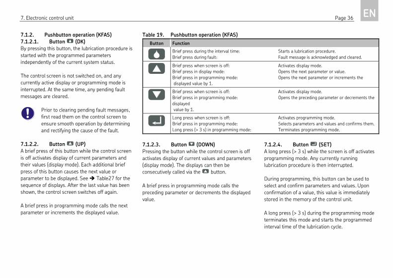
7.1.2. Pushbutton operation (KFAS)
7.1.2.1. Button (DK)
By pressing this button, the lubrication procedure is
started with the programmed parameters
independently of the current system status.
The control screen is not switched on, and any
currently active display or programming mode is
interrupted. At the same time, any pending fault
messages are cleared.
Prior to clearing pending fault messages,
first read them on the control screen to
ensure smooth operation by determining
and rectifying the cause of the fault.
7.1.2.2. Button (UP)
A brief press of this button while the control screen
is off activates display of current parameters and
their values (display mode). Each additional brief
press of this button causes the next value or
parameter to be displayed. See Table27 for the
sequence of displays. After the last value has been
shown, the control screen switches off again.
A brief press in programming mode calls the next
parameter or increments the displayed value.
7.1.2.3. Button (DOWN)
Pressing the button while the control screen is off
activates display of current values and parameters
(display mode). The displays can then be
consecutively called via the button.
A brief press in programming mode calls the
preceding parameter or decrements the displayed
value.
7.1.2.4. Button (SET)
A long press (> 3 s) while the screen is off activates
programming mode. Any currently running
lubrication procedure is then interrupted.
During programming, this button can be used to
select and confirm parameters and values. Upon
confirmation of a value, this value is immediately
stored in the memory of the control unit.
A long press (> 3 s) during the programming mode
terminates this mode and starts the programmed
interval time of the lubrication cycle.
Table 19. Pushbutton operation (KFAS)
Button Function
Brief press during the interval time: Starts a lubrication procedure.
Brief press during fault: Fault message is acknowledged and cleared.
Brief press when screen is off: Activates display mode.
Brief press in display mode: Opens the next parameter or value.
Brief press in programming mode: Opens the next parameter or increments the
displayed value by 1.
Brief press when screen is off: Activates display mode.
Brief press in programming mode: Opens the preceding parameter or decrements the
displayed
value by 1.
Long press when screen is off: Activates programming mode.
Brief press in programming mode: Selects parameters and values and confirms them.
Long press (> 3 s) in programming mode: Terminates programming mode.

7. Electronic control unit Page 37 EN
Table 20. Explanation of display contents of the three-digit LED display (KFAS)
Display Explanation of
characters
Explanation Value range Factory setting
t = timer
PA = PAuse
"Interval time in timer mode" parameter
The displayed value(s) refer(s) to the interval time of
the lubrication cycle
0.1 h to 99.9 h 10 h
c = counter
PA = PAuse
"Interval time in counter mode" parameter
The displayed value(s) refer(s) to the interval time of
the lubrication cycle
1 - 999 Pulses -
t = timer
CO = COntact
"Contact time in timer mode" parameter
The displayed value(s) refer(s) to the contact time of
the lubrication cycle
0.1 min – 99.9 min
KFA…W.. designs min 0.6 min
configuration-
dependent
c = counter
CO = COntact
Special application. Not applicable to the piston
pump units with reservoir described in these
instructions.
- -
C = Cycle
O = OFF
P = Pressure
"Monitoring function" parameter CS - Progressive distributor monitoring using a
cycle switch.
PS - Setting not permitted
OFF - Progressive distributor monitoring is deactivated.
OFF
Cycle Switch Value for "monitoring function" parameter
Progressive distributor monitoring using one cycle
switch.
- -
Pressure Switch Setting not permitted - -
OFF Value for "monitoring function" parameter
Progressive distributor monitoring is deactivated.
- -
Continued on next page

7. Electronic control unit Page 38 EN
Continuation of Table 20. Explanation of display contents of the three-digit LED display (KFAS)
Display Explanation of
characters
Explanation Value range Factory setting
Fault Cycle Switch "Cycle switch" fault message
No signal from cycle switch during contact time.
- -
Fault Low Level "Fill level" fault message
The level in the reservoir has fallen below the minimum fill level.
- -
Operation
hour meter
Operating hour meter
The following figures indicate the operating hours of the control unit.
Two display values appear:
Display 1: The first three digits of the value.
Display 2: The last two digits and one decimal place.
0.1 – 99999.9 hours
not deletable
0 hours
Fault hour meter
Fault hour meter
The following figures indicate the fault hours of the control unit.
Two display values appear:
Display 1: The first three digits of the value.
Display 2: The last two digits and one decimal place.
0.1 – 99999.9 hours
not deletable
0 hours
block Block mode
No signal from cycle switch. Unlike in normal mode, the control unit is
still in the monitoring sequence. A fault message is issued if the fault
remains for three contact times.
- -

7. Electronic control unit Page 39 EN
7.1.3. Programming (KFAS)
7.1.3.1. Starting programming mode (KFAS)
Programming mode can only be opened if the
display is off.
Long press (> 3 s) the button to switch on the
screen and start programming mode.
When programming mode is activated, any currently
active lubrication procedure is interrupted. After
exiting programming mode, a new lubrication cycle
is started with the current values and parameters if
no fault message is present. The lubrication cycle
starts with the interval time.
During programming, the PAUSE, CONTACT, or CS
LEDs flash, depending on the parameters that are
currently being adjusted.
Table 21. Starting programming mode (KFAS)
Step Button Action Display
1
Press longer than 3 s.
000 is displayed.
The three-digit LED display flashes.
Step 2 follows if the factory-set programming code 000 has already been changed
otherwise go straight to step 3.
2
Press repeatedly until
the current
programming code is
set.
The current programming code is displayed.
Example: 666
The three-digit LED display flashes.
3
Press briefly.
(confirm code)
The first adjustable parameter is displayed.
Example: Interval time in timer mode
The PAUSE LED flashes.

7. Electronic control unit Page 40 EN
7.1.3.2. Set interval time and contact time
(KFAS)
First activate programming mode ( Table21). The
interval time is displayed as the first adjustable
parameter.
Set the interval time and the contact time as
described in Table22. Observe the value ranges
in Table20 or in the Technical Data. The
PAUSE or CONTACT LEDs will flash while you make
the changes.
Table 22. Set interval time and contact time (KFAS)
Step Button Action Display
Programming mode is active.
The first adjustable parameter is displayed.
Example: Interval time in timer mode
The PAUSE LED flashes.
1
Press briefly.
(select the parameter)
The current value for the interval time is
displayed.
Example: 24 h
The PAUSE LED flashes.
2
Press repeatedly until
the desired value is set.
The new value is displayed.
Example: 36 h
The PAUSE LED flashes.
3
Press briefly.
(confirm the new value)
Display the next parameter.
Example: Contact time in timer mode
The CONTACT LED flashes.
The new value for the "interval time"
parameter has been confirmed and stored
in the control unit's non-volatile memory.
Continued on next page

7. Electronic control unit Page 41 EN
Continuation of Table 22. Set interval time and contact time (KFAS)
Step Button Action Display
4
Press briefly.
(select the parameter)
The current value for the contact time is displayed.
Example: 6.5 min (6 min 30 s)
The CONTACT LED flashes.
5
Press repeatedly until the desired
value is set.
The new value is displayed.
Example: 8 min
The CONTACT LED flashes.
6
Press briefly.
(confirm the new value)
Display the next parameter.
Example: Monitoring function
The CS and PS LEDs flash.
The new value for the "contact time" parameter has been confirmed and stored in the
control unit's non-volatile memory.
7
Press longer than 3 s.
The display clears.
A new lubrication cycle is started beginning with the interval time.

7. Electronic control unit Page 42 EN
7.1.3.3. Set monitoring functions (KFAS)
First activate programming mode ( Table21).
Switch the monitoring function on or off as
described in Table23. Observe the value ranges
in Table20 or in the Technical Data.
The CS or PS LEDs will flash while you make the
changes.
Table 23. Set monitoring functions (KFAS)
Step Button Action Display
Programming mode is active.
The first adjustable parameter is displayed.
Example: Interval time in timer mode
The PAUSE LED flashes.
1
Press repeatedly
until COP is
displayed.
The "monitoring function" parameter is
displayed.
The type of progressive distributor monitoring
can now be changed.
The CS and PS LEDs flash.
2
Press briefly.
(select the
parameter)
The current value for the "monitoring function"
parameter is displayed.
Example: OFF (progressive distributor
monitoring is off)
The CS and PS LEDs flash.
3
Press repeatedly
until the desired
value is set.
The display changes between OFF, CS, and PS.
OFF – Progressive distributor monitoring is deactivated.
CS – Progressive distributor monitoring using one cycle switch is active.
PS – Setting not permitted
The CS and/or PS LEDs flash.
4
Press briefly.
(confirm the new
value)
The new setting has been confirmed and stored in the control unit's non-
volatile memory.
5
Press longer than 3
s.
The display clears.
A new lubrication cycle is started beginning with the interval time.

7. Electronic control unit Page 43 EN
7.1.3.4. Change mode of operation (KFAS)
First activate programming mode. ( Table21).
Change the mode of operation as described in
Table24. Observe the information in Chapter
3.5.1, "Modes of operation" as well as the value
ranges in Table20 and/or in the Technical
Data.
The PAUSE LED will flash while you make the
changes.
Table 24. Change mode of operation (KFAS)
Step Button Action Display
Programming mode is active.
The first adjustable parameter is displayed.
Example: Interval time in timer mode
The PAUSE LED flashes.
1
Press briefly.
The display changes from tPA to cPA.
tPA – Interval time in timer mode (values in hours)
cPA – Interval time in counter mode (values in pulses)
The PAUSE LED flashes.
2
Press briefly.
(confirm the new
value)
Display the next parameter.
Example: Contact time in timer mode
The CONTACT LED flashes.
The new value for the "interval time" parameter has
been confirmed and stored in the control unit's non-
volatile memory.
The change of the mode of operation is now complete. You can leave programming mode by long pressing (> 3 s) .
If desired, the duration of the interval time can also be set by entering the number of pulses.
Continued on next page

7. Electronic control unit Page 44 EN
Continuation of Table 24. Change mode of operation (KFAS)
Step Button Action Display
3
Press briefly.
The display switches back to the "interval time in counter mode" parameter.
The PAUSE LED flashes.
4
Press briefly.
(select the parameter)
The current value for the interval time is displayed.
Example: 24 pulses
The PAUSE LED flashes.
5
Press repeatedly until the
desired value is set.
The new value is displayed.
Example: 36 pulses
The PAUSE LED flashes.
6
Press briefly.
(confirm the new value)
Display the next parameter.
Example: Contact time in timer mode
The CONTACT LED flashes.
The new value for the "interval time" parameter has been confirmed and stored in the control
unit's non-volatile memory.
7
Press longer than 3 s. The display clears.
A new lubrication cycle is started beginning with the interval time.

7. Electronic control unit Page 45 EN
7.1.3.5. Change programming code (KFAS)
The programming code prevents settings on the
control unit from being adjusted accidentally. It must
be entered in order to access programming mode.
Setting a new programming code deletes
the factory default programming code and
activates the new value. Write down the
new value and store it in a safe place. The
parameters cannot be programmed if the
programming code is lost or forgotten. In
this case, the piston pump unit must be
sent to the dealer or authorized SKF
branch office.
Warning!
Do not enter the digits 321 as the new
programming code.
Table 25. Change programming code (KFAS)
Step Button Action Display
1
Press longer
than 3 s.
000 is displayed.
The three-digit LED display flashes.
2
Press either
until 321 is set.
The key code 321 is displayed.
The three-digit LED display flashes.
3
Press briefly
(confirm key
code).
The display returns to 000.
The three-digit LED display flashes.
If the programming code has already been changed, it must be entered again before making another change. Proceed
with step 5 if you want to reprogram the code.
4
Press either
until the old
code is set.
The old code is displayed.
Example: 333
The three-digit LED display flashes.
5
Press briefly
(confirm old
code).
Display the factory setting
000 or the new code,
Example: 333
The three-digit LED display
flashes.
6
Press either
until the new
code is set.
The new code is displayed.
Example: 666
The three-digit LED display flashes.
Warning! Do not enter 321.
7
Press briefly
(confirm new
code).
The new value for the programming code has been confirmed and stored in the
control unit's non-volatile memory.
8
Press longer
than 3 s.
The display clears.
A new lubrication cycle is started beginning with the interval time.

7. Electronic control unit Page 46 EN
7.1.4. Operation of KFAS (industrial and
commercial vehicles)
7.1.4.1. LED displays on the control screen
during operation (KFAS)
During operation, you should regularly check the
LED displays on the control unit's control screen (
Table26).
Further information about the operating state and
the set parameters can be queried in display mode
( next Chapter).
Table 26. LED displays on the control screen during operation (KFAS)
LED LED lights up
Operating voltage is present on the piston pump unit and the control unit.
The centralized lubrication system is currently in the interval time.
Operating voltage is present on the piston pump unit and the control unit.
The centralized lubrication system is currently in the contact time.
During the contact time:
Progressive distributor monitoring using one cycle switch is active.
Not assigned
Fault
The operational sequence has been stopped or
the piston pump unit is currently in block mode ( Chapter 3.5.6, "Block mode").
Additional information can be accessed by pressing or
( Chapter 7.1.5, "KFAS fault indications").

7. Electronic control unit Page 47 EN
7.1.4.2. Display mode (KFAS)
During normal operation, the three-digit LED
display is switched off and, depending on the
operating state, only the PAUSE, CONTACT, CS, or
FAULT LEDs light up ( preceding Chapter).
To display the current operating parameters, the
three-digit LED display is activated by briefly
pressing one of the two buttons or . The LED
display is then in display mode.
In display mode, you can query the current
parameters and their values one by one. The
procedure is shown in Table27.
Table20 in Chapter 7.1.1, "Display and control
elements (KFAS)" shows an overview of the possible
display contents, their meaning and the value range.
Table 27. Display of parameters in display mode (KFAS)
Step Button Display
1
Press briefly.
Display mode is activated.
The current operating state is displayed.
Example: Interval time in timer mode
2
Display of remaining interval time in the current lubrication cycle
Example: 3.8 h
If a lubrication procedure is currently being executed (CONTACT
LED lights up), --- is displayed.
3
Display of the programmed total interval time
Example: 1 h
4
Switchover to the "contact time" parameter.
Example: Contact time in timer mode
5
Display of the remaining contact time for current lubrication
cycle
Example: The centralized lubrication system is currently in the
interval time; the remaining contact time therefore cannot be
displayed.
6
Display of the programmed contact time
Example: 4 min
7
Switchover to the "monitoring function" parameter.
Continued on next page

7. Electronic control unit Page 48 EN
Continuation of Table 27. Display of parameters in display mode (KFAS)
Step Button Display
8
Display of the monitoring function status.
Example:
Progressive distributor
monitoring is switched off.
or:
Progressive distributor monitoring using
one cycle switch is active.
9
Operation hour meter
The operation hours are displayed in two parts:
10/11
Example:
1st part of total value
2nd part of total value
Total value: 533.8 h
12
Fault hour meter
The fault hours are displayed in two parts:
13/14
Example:
1st part of total value
2nd part of total value
Total value: 33.8 h
15
The display clears.

7. Electronic control unit Page 49 EN
7.1.5. KFAS fault indications
7.1.5.1. Display of faults (KFAS)
When progressive distributor monitoring is active
and depending on whether the piston pump unit is
equipped with a fill level switch, the electronic
control unit will display the malfunctions listed in
Table28.
Fault indication
o FAULT LED lights up.
Read fault message
The fault message can be read on the control screen
in view mode:
• Briefly press or to activate display
mode.
• Press until a fault message is displayed.
Table 28. Fault messages (KFAS)
Display Meaning
Fault Cycle Switch:
No signal from cycle switch during
contact time.
The centralized lubrication system is
currently in block mode ( Chapter
3.5.6, "Block mode").
Fault Low Level:
The minimum fill level in the lubricant
reservoir has been reached.
The operational sequence has been
stopped.
7.1.5.2. Delete fault messages (KFAS)
The fault messages are acknowledged and cleared
by pressing the button. At the same time, a new
lubrication procedure is started.
Warning!
Prior to clearing a fault message, the
cause of the fault must be determined and
rectified.
7.1.5.3. Fault hour meter (KFAS)
The time which has elapsed between the occurrence
of the fault message and the rectification of the
fault is stored in the non-volatile memory of the
control unit as a fault hours figure.
When this is done, all fault state-times counted
during the entire operating time of the piston pump
unit are summed. The current count can be read as
described in Chapter 7.1.4.2, "Display mode
(KFAS)."
The memory cannot be deleted.
8. Shutdown Page 50 EN
8. Shutdown 8.1. Temporary shutdown
The described product can be temporarily shut
down by disconnecting the electrical, pneumatic,
and/or hydraulic supply connections. The
instructions in Chapter 1, "Safety instructions" in
these owner’s manual must be observed when doing
so.
If the product is to be shut down for an extended
period of time, follow the instructions in Chapter
5, "Transport, delivery, and storage" in these
owner’s manual.
To recommission the product, follow the instructions
in Chapters 4, "Assembly instructions" und 6,
"Operation" in these owner’s manual.
8.2. Permanent shutdown
If the product will be permanently shut down, the
local regulations and laws regarding the disposal of
contaminated equipment must be observed.
Warning!
Lubricants can contaminate soil and bodies
of water. Lubricants must be used and
disposed of properly. Observe the local
regulations and laws regarding the
disposal of lubricants.
The product can also be returned to SKF Lubrication
Systems Germany GmbH for disposal, in which case
the customer is responsible for reimbursing the
costs incurred.

9. Maintenance Page 51 EN
9. Maintenance 9.1. General notes
Danger!
Performing work on an energized pump or
product may result in serious injury or
death. Assembly, maintenance, and repair
work may only be performed on products
that have been de-energized by qualified
technical personnel. The supply voltage
must be switched off before opening any of
the product's components.
Danger!
Centralized lubrication systems are
pressurized during operation. Centralized
lubrication systems must therefore be
depressurized before starting assembly,
maintenance or repair work, or any system
modifications or system repairs.
Danger!
The described product is pressurized
during operation. The product must
therefore be depressurized before starting
assembly, maintenance or repair work, or
any system modifications or system
repairs.
Products from SKF Lubrication Systems Germany
GmbH are low-maintenance. However, all
connections and fittings must be regularly inspected
for proper seating to ensure proper function and to
prevent hazards from arising.
SKF Lubrication Systems Germany GmbH shall not
be held liable for damages resulting from improperly
performed assembly, maintenance or repair work on
the product.
9.2. Cleaning
If necessary, the product can be cleaned using mild
cleaning agents that are compatible with the
product's materials (non-alkaline, non-soap). For
safety reasons, the product should be disconnected
from the power supply and the hydraulic and/or
compressed air supply.
Do not allow any cleaning agent to enter the interior
of the product during cleaning.
It is not necessary to clean the interior of the
product if the product is operated normally and
intercompatible lubricants are used.
The interior of the product must be cleaned if
incorrect or contaminated lubricant is accidentally
filled into the product. If this occurs, please contact
the Service department of SKF Lubrication Systems
Germany GmbH for assistance.
Dismantling of the product or individual
parts thereof within the statutory warranty
period is not permitted and voids any
claims.
9.3. Replacing the pump element
Only original spare parts from SKF
Lubrication Systems Germany GmbH may
be used. Unauthorized alterations to
products and the use of non-original spare
parts and accessories are prohibited and
nullify the statutory warranty.
Too little or no lubricant will be delivered if a pump
element is worn out. After removing the main
lubricant line and the pressure regulating valve, you
can keep the outlet port of the pump element closed
with a finger when the piston pump unit operates to
deliver lubricant. This is a sign that the element is
worn.

9. Maintenance Page 52 EN
Step 1:
Unscrew pump element. If the piston of the pump
element gets stuck in the lubricant present in the
strainer ring, remove it with a suitable tool
( Fig.30).
Step 2:
Remove bothersome lubricant between the internal
thread, guide slot in the strainer ring and the groove
between the cam disc and return disc with a suitable
tool.
The pump elements are fitted only with O-
ring 15.4x2.1 (1) without any additional
sealing ring.
( Fig.31).
Fig.30. Removing the piston
Step 3:
Pull piston of the new pump element as far as
possible out of the element, and insert it along the
guide slot of the strainer ring between the cam disc
and return disc ( Fig.32). If the pump element has
not been correctly installed, it is not possible to
tighten the thread.
The piston pump unit must be vented after
replacement of the pump element.
1
Fig.31. Pump element with O-ring (item 1)
1243
Fig.32. Sectional top view of pump housing
1 Internal thread
2 Guide slot in strainer ring
3 Cam disc
4 Return disc
Fig.33. Inserting the pump element

10. Malfunctions Page 53 EN
10. Malfunctions 10.1. Fault indications on piston pump
units without control unit
10.1.1. Piston pump units without fill level
monitoring (KFA..)
These piston pump units are not equipped with a
display function for faults. Operational malfunctions
can only be detected by external monitoring (visual
or sensory).
10.1.2. Piston pump units with integrated fill
level monitoring (KFA..-W)
When using these piston pump units, an insufficient
fill level in the lubricant reservoir is indicated by a
signal issued via one of the electrical connectors.
( Chapter 4.4, "Electrical connection")
10.2. Fault analysis and rectification
Table29 provides an overview of possible
malfunctions and their causes. Contact the Service
department of SKF Lubrication Systems Germany
GmbH if you cannot remedy the malfunction.
Table 29 Fault analysis and rectification
Malfunction Possible cause Rectification
Electric motor does
not start.
No operating voltage at the
motor, pump
blocked.
KFAS
Check electrical connection.
Pump does not
convey lubricant; no
pressure build-up
Insufficient fill level. Top up lubricant ( Chapter 6.2, "Filling the lubricant
reservoir").
Check fill level switch, if installed.
Wrong lubricant,
( Chapter 2 "Lubricants").
Replace lubricant in the entire centralized lubrication system;
beforehand, remove all old lubricant and dispose of it properly.
Air in the centralized lubrication
system.
Vent centralized lubrication system. The lubricant must
discharge without bubbles at the lubricant outlet ( Chapter
6.3, "Vent centralized lubrication system").
During operation, the
lubrication points are
supplied insufficiently
or not at all.
Metering volume too low. Reduce interval time.
Air in the centralized lubrication
system.
Vent centralized lubrication system. The lubricant must
discharge without bubbles at the lubricant outlet ( Chapter
6.3, "Vent centralized lubrication system").
Main lubricant line too long,
cross-section too small
(pressure regulating valve
opens).
Check the lubricant transport through the main lubricant line
and, if required, relocate the piston pump unit.
Wrong lubricant,
( Chapter 2 "Lubricants").
Replace lubricant in the entire centralized lubrication system;
beforehand, remove all old lubricant and dispose of it properly.
Lubrication line leaky. Check connections.
Piston pump unit worn out. Replace entire piston pump unit.
Progressive distributor
defective.
Replace entire piston pump unit.

10. Malfunctions Page 54 EN
Danger!
Performing work on an energized pump or
product may result in serious injury or
death. Assembly, maintenance, and repair
work may only be performed on products
that have been de-energized by qualified
technical personnel. The supply voltage
must be switched off before opening any of
the product's components.
Danger!
The hot surface of a motor may cause
burns. Motor surfaces may only be
touched with appropriate gloves or after
the motor has been shut off for an
extended time.
Danger!
Centralized lubrication systems are
pressurized during operation. Centralized
lubrication systems must therefore be
depressurized before starting assembly,
maintenance or repair work, or any system
modifications or system repairs.
Dismantling of the product or individual
parts thereof within the statutory warranty
period is not permitted and voids any
claims.
All assembly, maintenance and repair work
beyond this scope must be performed by
the Service department of SKF Lubrication
Systems Germany GmbH .
Only original spare parts from SKF
Lubrication Systems Germany GmbH may
be used. Unauthorized alterations to
products and the use of non-original spare
parts and accessories are not permitted.
Continuation of Table 29 Fault analysis and rectification
Malfunction Possible cause Rectification
Excessive lubricant at
all lubrication points.
Metering volume too high. Increase the interval time.
Individual lubrication
points are not
supplied.
Lubrication line is clogged. Clean lubrication lines.
Lubrication line bent or broken. Replace affected lubrication lines, insert filled lubrication
lines.
Distributor defective. Replace entire piston pump unit.
Lubrication line too long. Relocate the piston pump unit, shorten lubrication lines
(max. 6 m).
Individual lubrication
points receive
insufficient or
excessive lubrication.
Metering volume too low or too
high.
Connect the secondary feeder, if required, install a second
pump unit with a reduced delivery rate to supply the second
distributor. Supply lubrication points with lower lubrication
requirements using the secondary distributor (2nd
distributor) and lubrication points with higher lubrication
requirements using the master distributor. In case of
insufficient lubrication, reduce the interval time. In case of
excessive lubrication, prolong it accordingly.
Please contact SKF.

11. Technical data Page 55 EN
11. Technical data
Table 30. Technical data
Piston pump unit with
reservoir
Unit KFA1-(W)..,
KFAS1-(W)..
KFA1-M-(W)..,
KFAS1-M-(W)..
KFAS10-(W) KFA10-(W) Remark
General
Delivery rate 1.)
Operating pressure
Number of outlets
Ambient temperature
Rated capacity of reservoir
Reservoir material
Protection class
Grease NLGI Grade
Flow pressure
cm3/min
cm3/min
bar
°C
liter
mbar
1.0; 1.5; 2.0
max. 300
max. 2
-25 to +75
1
Plastic
IP 6K9K
up to 2
max. 700
1.0; 1.5; 2.0
max. 300
max. 2
-25 to +75
1
Plastic
IP 55
up to 2
max. 700
1.0; 1.5; 2.0
max. 300
max. 2
-25 to +60
1
Plastic
IP 55
up to 2
max. 700
1.0; 1.5; 2.0 at 50 Hz
1.2; 1.8; 2.4 at 60 Hz
max. 300
max. 2
0 to +40
1
Plastic
IP 55
up to 2
max. 700
AC motor
Rated voltage
Power consumption 2.)
Rated frequency
Mode of operation
Type
V AC
A
A
Hz
-
-
-
-
-
-
-
-
-
-
-
-
-
-
-
-
-
-
Split-pole motor
115 / 230
115V: 1.54 / 1.08 (50/60 Hz)
230V: 0.77 / 0.54 (50/60 Hz)
50 / 60
S3 5% - 100 min
DC motor
Rated voltage
Power consumption 2.)
Mode of operation
Type
V DC
A
Brushed motor
12 / 24
1 / 0.5
S3 20% - 50 min
Brushed motor
24
0.5
S3 20% - 50 min
Brushed motor
24
S3 20% - 50 min
-
-
-
-
Switch-mode power supply,
integrated
Voltage, input
Current, input
Current, inrush
Frequency, input
Overload protection
Overvoltage protection
V AC
A
A
A
A
Hz
none
-
-
-
-
-
-
-
-
none
-
-
-
-
-
-
-
-
yes
85 - 264
0.65 (115V)
0.4 (230V)
20 (115V)
40 (230V)
47 - 63
yes
yes
none
-
-
-
-
-
-
-
-

11. Technical data Page 56 EN
Continuation of Table 30. Technical data
Piston pump unit with
reservoir
Unit KFA1-(W)..,
KFAS1-(W)..
KFA1-M-(W)..,
KFAS1-M-(W)..
KFAS10-(W) KFA10-(W) Remark
Fill level switch
Function
Rated voltage, max.
Switched current, max.
Switching capacity, max.
V DC
A
W
NC contact
24
0.5
20
NC contact
24
0.5
20
NC contact
24
0.5
20
NC contact
24
0.5
20
Control unit
Interval time, adjustable
(see "Mode of operation")
Contact time (pump cycle
time), adjustable
(see "Mode of operation")
Operation hour meter
Fault hour meter
Monitoring of external cycle
switches, adjustable
Modes of operation
IG502-2-I with control unit and screen
0.1…99.9 / 1...999 h / pulses (timer/counter mode)
Factory setting: tPA = 10 h
0.1 ... 99.9 min
KFA…W.. designs: min 0.6 min
Factory setting:tCO = 2.0 min
0.1 ... 99999.9 h (not deletable)
Factory setting: 0.0 h
0.1 ... 99999.9 h (not deletable)
Factory setting: 0.0 h
COP = CS (monitoring is active)
COP = OFF (monitoring is inactive)
Factory setting: COP = OFF
Counter or timer mode
Factory setting: Timer operation
none
1) With NGLI Grade 2 grease, back pressure p = 50 bar and ambient temperature T = 20 °C, depends on pump element (see Table in Chapter 3.2, "Pump elements") 2) With max. operating pressure p = 300 bar and ambient temperature T = 20°C

Blank page

Blank page

Blank page

Order number: 951-170-008
Subject to changes in contents and technical information.
Last modified: 19.07.2018
The contents of this publication are the copyright of the publisher and may not be reproduced in whole or in part without permission of SKF Lubrication Systems
Germany GmbH . Every care has been taken to ensure the accuracy of the information contained in this publication. However, no liability can be accepted for any
loss or damage whether direct, indirect or consequential, arising out of use of the information contained herein.
All SKF Lubrication Systems Germany GmbH products may be used only for their intended purpose as described in these owner’s manual with associated
operating instructions. If assembly/operating instructions are supplied together with the products, they must be read and followed.
Not all lubricants can be fed using centralized lubrication systems. SKF can, on request, inspect the suitability of the lubricants selected by the user for pumping
in centralized lubrication systems. Lubrication systems and their components manufactured by SKF Lubrication Systems Germany GmbH are not approved for
use in conjunction with gases, liquefied gases, pressurized gases in solution, vapors or such fluids whose vapor pressure exceeds normal atmospheric pressure
(1013 mbar) by more than 0.5 bar at their maximum permissible temperature.
Hazardous materials of any kind, especially the materials classified as hazardous by CLP Regulation EC 1272/2008 may only be used to fill SKF centralized
lubrication systems and components and deliv-ered and/or distributed with the same after consulting with and receiving written approval from SKF.
SKF Lubrication Systems Germany GmbH
Plant Berlin Plant Hockenheim
Motzener Strasse 35/37 2. Industriestrasse 4
12277 Berlin 68766 Hockenheim
Germany Germany
Tel. +49 (0)30 72002-0 Tel. +49 (0)62 05 27-0
Fax +49 (0)30 72002-111 Fax +49 (0)62 05 27-101
www.skf.com/lubrication
® SKF is a registered trademark of the SKF Group.
© SKF Group 2018