Embed Size (px)
Citation preview

MAKE OF AUTOMOBILE: LADATYPE: KALINA 1117/ 1118 / 1119PISTON DISPLACEMENT: 1600NUMBER OF VALVES: 8ENGINE NUMBER: 21114TRANSMISSION TYPE ( MT / AT ) MTVEHICLE CATEGORIES M or N M TYPE VSI INJECTOR ( NUMBER + COLOR ) 180/30420 BLUEVERSION ( LPG / CNG ) LPGINJECTION SYSTEM: BOSCH MOTRONICMODEL YEAR: 2007SYSTEM APPROVAL NUMBER ( R115 ) R115-000023 LOCATION SYSTEM STICKER Right side centre door post ENGINE SET NUMBER 350/1290000
NUMBER : 076/1001700
DATE : 2008-04-14Copyright © Prins Autogassystemen B.V. 2008 VERSION NR : 2008-02-14 B
TABLE OF CONTENTS
Required equipment / tools / materials for installing a complete system ...........................................2
Vehicle check......................................................................................................................................2
Base diagram......................................................................................................................................3
Mounting and connection points .........................................................................................................4
VSI approval numbers ........................................................................................................................5
Mounting the reducer ..........................................................................................................................6
Routing water connections .................................................................................................................7
Mounting the inlet manifold couplings.................................................................................................8
Mounting the VSI injector rail ..............................................................................................................9
Mounting the filter unit...................................................................................................................... 10
LPG hoses ....................................................................................................................................... 10
Mounting the VSI computer ............................................................................................................. 11
Mounting the fuel selection switch ................................................................................................... 12
Electrical connections ...................................................................................................................... 13
Electrical connections ...................................................................................................................... 14
Checklist after installation ................................................................................................................ 15
Trouble code chart ........................................................................................................................... 16
FOR EXPLANATION AND CIRCUIT DIAGRAMS SEE : INSTALLATION MANUAL GENERAL PART 1 / 2 www.Prins.eu
EXPLANATION OF SYMBOLS :
= IMPORTANT, CAUTION
PAGE 2 076/1001700Copyright © Prins Autogassystemen B.V. 2008 LADA KALINA 1.6i 8V 21114 VERSION NR : B
2
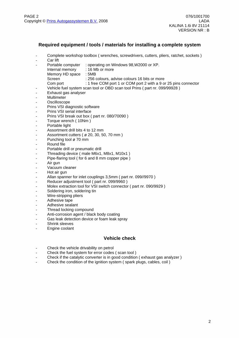
Required equipment / tools / materials for installing a complete system
- Complete workshop toolbox ( wrenches, screwdrivers, cutters, pliers, ratchet, sockets ) - Car lift - Portable computer : operating on Windows 98,W2000 or XP.
Internal memory : 16 Mb or more Memory HD space : 5MB Screen : 256 colours, advise colours 16 bits or more Com port : 1 free COM port 1 or COM port 2 with a 9 or 25 pins connector
- Vehicle fuel system scan tool or OBD scan tool Prins ( part nr. 099/99928 ) - Exhaust gas analyser - Multimeter - Oscilloscope - Prins VSI diagnostic software - Prins VSI serial interface - Prins VSI break out box ( part nr. 080/70090 ) - Torque wrench ( 10Nm ) - Portable light - Assortment drill bits 4 to 12 mm - Assortment cutters ( ø 20, 30, 50, 70 mm ) - Punching tool ø 70 mm - Round file - Portable drill or pneumatic drill - Threading device ( male M6x1, M8x1, M10x1 ) - Pipe-flaring tool ( for 6 and 8 mm copper pipe ) - Air gun - Vacuum cleaner - Hot air gun - Allan spanner for inlet couplings 3,5mm ( part nr. 099//9970 ) - Reducer adjustment tool ( part nr. 099/9960 ) - Molex extraction tool for VSI switch connector ( part nr. 090/9929 ) - Soldering iron, soldering tin - Wire-stripping pliers - Adhesive tape - Adhesive sealant - Thread locking compound - Anti-corrosion agent / black body coating - Gas leak detection device or foam leak spray - Shrink sleeves - Engine coolant
Vehicle check
- Check the vehicle drivability on petrol - Check the fuel system for error codes ( scan tool ) - Check if the catalytic converter is in good condition ( exhaust gas analyzer ) - Check the condition of the ignition system ( spark plugs, cables, coil )
PAGE 3 076/1001700Copyright © Prins Autogassystemen B.V. 2008 LADA KALINA 1.6i 8V 21114 VERSION NR : B
3
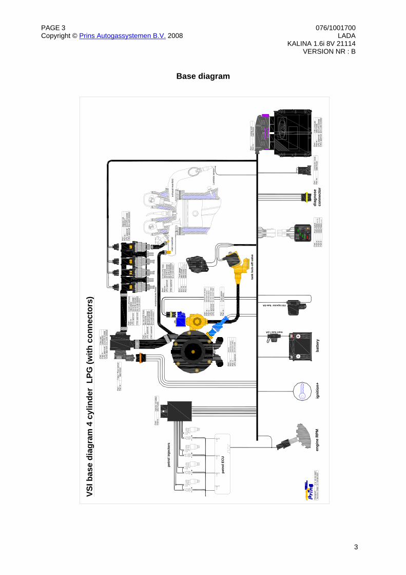
Base diagram
P
art :
Par
t nr.
:LP
G a
ppro
val :
CN
G a
ppro
val :
Filte
r uni
t08
0/80
200
E4-
67R
-010
096
E4-
110R
-000
028
Par
t :P
art n
r. :
T-ec
t sen
sor
077/
7000
1
Part
:Pa
rt nr
. :LP
G a
ppro
val :
CN
G a
ppro
val :
Inje
ctor
rail
180/
304*
*E
4-67
R-0
1009
3E
4-11
0R-0
0002
1
Par
t :P
art n
r. :
Fuel
sw
itch
080/
7005
8 H
all /
Ohm
Par
t :P
art n
r. :
LPG
app
rova
l :C
NG
app
rova
l :
VSI
com
pute
r08
0/70
001
E4-
67R
-010
098
E4-
110R
-010
083
Par
t :P
art n
r. :
LPG
app
rova
l :
redu
cer l
ock-
off v
alve
081/
1300
7 (6
mm
)P
art n
r. :
081/
1301
4 (8
mm
)E
4-67
R-0
1004
1 Va
ltec
LPG
app
rova
l :E
4-67
R-0
1432
7 O
MB
Par
t nr.
:08
0/70
059
93-9
,3 O
hm
Par
t nr.
:08
0/70
063
0-5
Volt
Par
t :P
art n
r. :
Tank
gau
ge08
0/70
065
Hal
l
Par
t nr.
:08
0/70
064
0-90
Ohm
Par
t nr.
:08
5/20
020
0-95
Ohm
Par
t :P
art n
r. :
Inje
ctor
sim
ulat
or09
1/71
004
BLA
CK
B
LU
E
GR
OU
ND
SI
GN
AL
PRIN
S
1
012
-+
petro
l inj
ecto
r
inle
t man
ifold
exha
ust m
anifo
ld
Lam
bda
sens
or
petr
ol E
CU
VSI b
ase
diag
ram
4 c
ylin
der
LPG
(with
con
nect
ors)
engi
ne R
PMig
nitio
n+ba
ttery
diag
nose
conn
ecto
r
main fuse 7,5A
tank
lock
-off
valv
e
Par
t :P
art n
r. :
LPG
app
rova
l :
redu
cer
180/
1000
1 (6
mm
)P
art n
r. :
180/
1001
0 ( M
AP )
E4-6
7R-0
1005
4
Par
t :P
art n
r. :
T-lp
g +
Psys
sen
sor
080/
7003
2
Par
t :P
art n
r. :
LPG
app
rova
l :
CN
G a
ppro
val :
11 m
m L
PG
hos
e08
1/24
003
E4-
67R
-010
068
E4-
110R
-000
003
Par
t :P
art n
r. :
LPG
app
rova
l :
CN
G a
ppro
val :
16 m
m L
PG
hos
e08
1/25
001
E4-
67R
-010
145
Par
t :P
art n
r. :
LPG
app
rova
l :
CN
G a
ppro
val :
5 m
m L
PG h
ose
081/
2300
1E
4-67
R-0
1006
8
Par
t :P
art n
r. :
conn
ecto
r cov
er08
0/70
130
Des
igne
d :
Ver
sion
/ D
ate
:T.S
. 22-
01-2
007
2 / 0
6-06
-200
7
VSI injector fuse 5A
over
pres
sure
hos
e
Part
:Pa
rt nr
. :w
iring
loom
180/
7000
4
E4-
67R
-010
145
E13
-110
R-0
0001
7
E4-
67R
-010
068
E4-
110R
-000
003
E4-
67R
-010
145
E4-
110R
-000
003
E13
-110
R-0
0001
7
E13
-110
R-0
0001
7
petr
ol in
ject
ors
+ -
+ -
+ -
+ -
PAGE 4 076/1001700Copyright © Prins Autogassystemen B.V. 2008 LADA KALINA 1.6i 8V 21114 VERSION NR : B
4
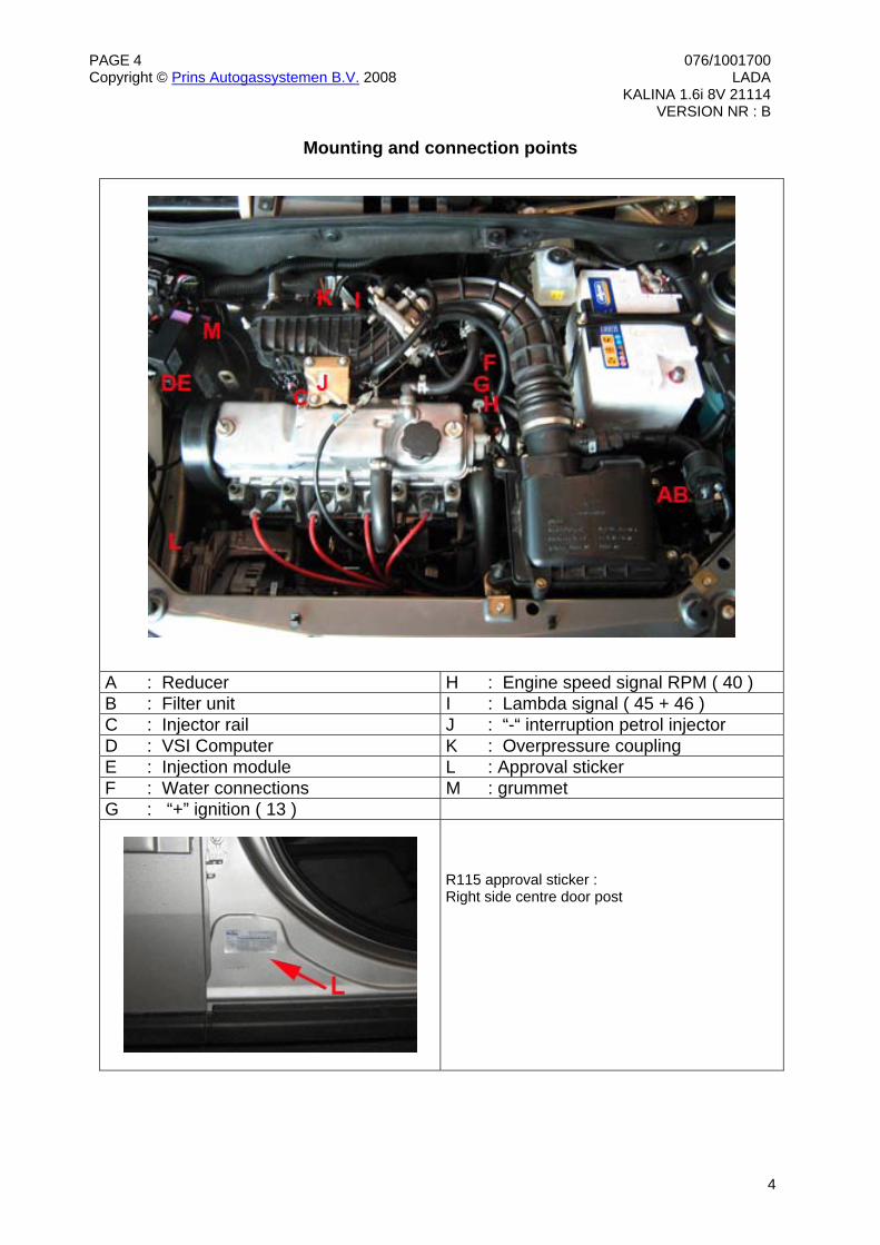
Mounting and connection points
A : Reducer H : Engine speed signal RPM ( 40 ) B : Filter unit I : Lambda signal ( 45 + 46 ) C : Injector rail J : “-“ interruption petrol injector D : VSI Computer K : Overpressure coupling E : Injection module L : Approval sticker F : Water connections M : grummet G : “+” ignition ( 13 )
R115 approval sticker : Right side centre door post
PAGE 5 076/1001700Copyright © Prins Autogassystemen B.V. 2008 LADA KALINA 1.6i 8V 21114 VERSION NR : B
5
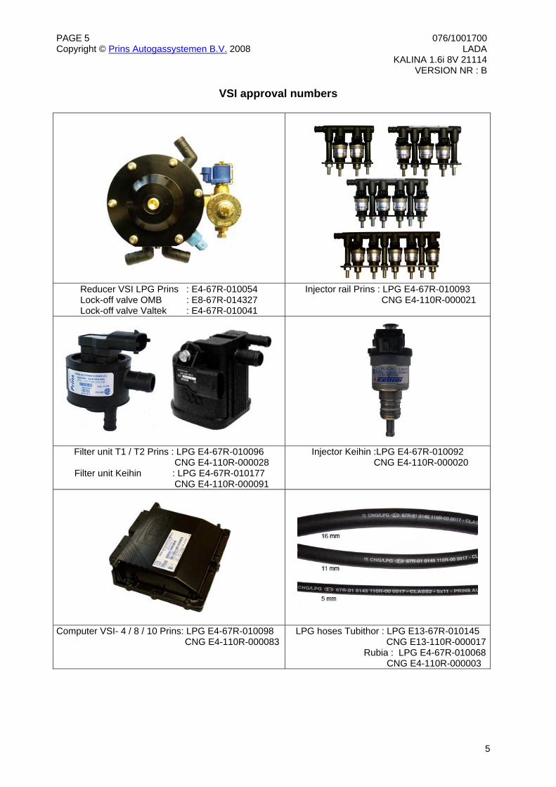
VSI approval numbers
Reducer VSI LPG Prins : E4-67R-010054 Lock-off valve OMB : E8-67R-014327 Lock-off valve Valtek : E4-67R-010041
Injector rail Prins : LPG E4-67R-010093 CNG E4-110R-000021
Filter unit T1 / T2 Prins : LPG E4-67R-010096 CNG E4-110R-000028
Filter unit Keihin : LPG E4-67R-010177 CNG E4-110R-000091
Injector Keihin :LPG E4-67R-010092 CNG E4-110R-000020
Computer VSI- 4 / 8 / 10 Prins: LPG E4-67R-010098 CNG E4-110R-000083
LPG hoses Tubithor : LPG E13-67R-010145 CNG E13-110R-000017 Rubia : LPG E4-67R-010068
CNG E4-110R-000003
PAGE 6 076/1001700Copyright © Prins Autogassystemen B.V. 2008 LADA KALINA 1.6i 8V 21114 VERSION NR : B
6
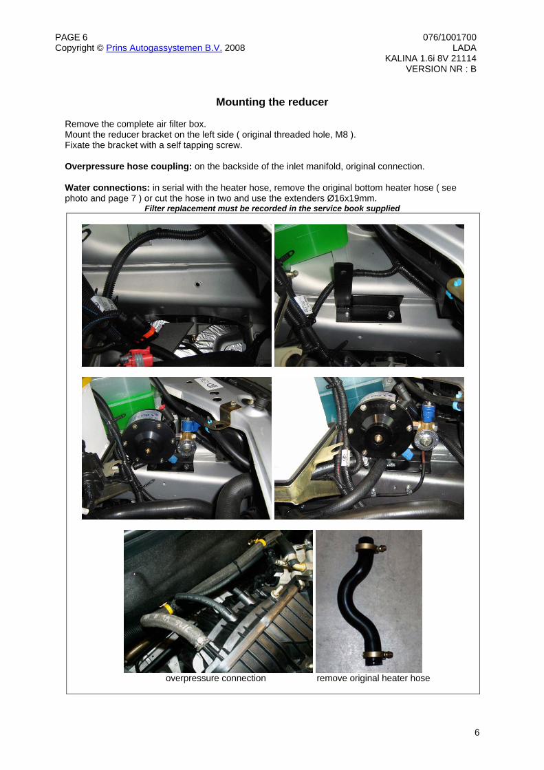
Mounting the reducer
Remove the complete air filter box. Mount the reducer bracket on the left side ( original threaded hole, M8 ). Fixate the bracket with a self tapping screw. Overpressure hose coupling: on the backside of the inlet manifold, original connection. Water connections: in serial with the heater hose, remove the original bottom heater hose ( see photo and page 7 ) or cut the hose in two and use the extenders Ø16x19mm.
Filter replacement must be recorded in the service book supplied
overpressure connection remove original heater hose
PAGE 7 076/1001700Copyright © Prins Autogassystemen B.V. 2008 LADA KALINA 1.6i 8V 21114 VERSION NR : B
7
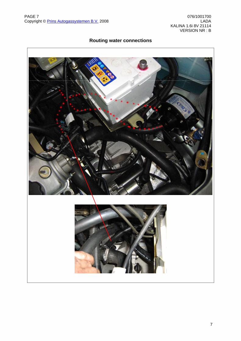
Routing water connections
PAGE 8 076/1001700Copyright © Prins Autogassystemen B.V. 2008 LADA KALINA 1.6i 8V 21114 VERSION NR : B
8
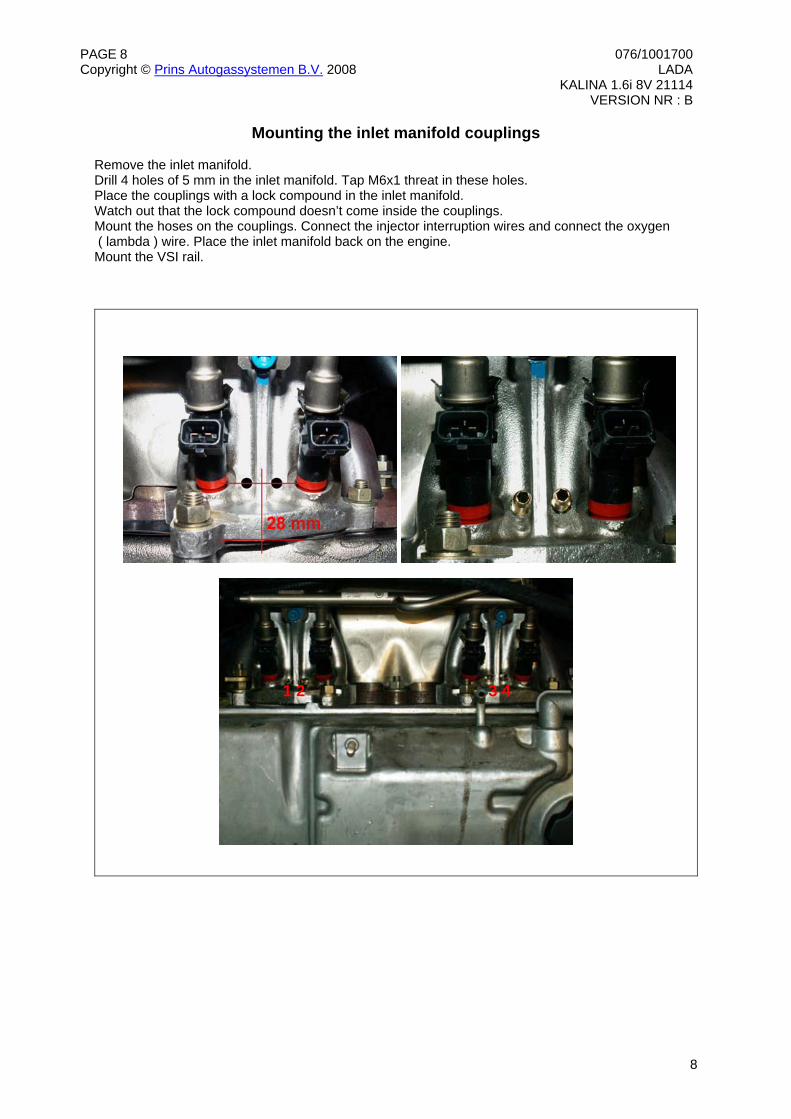
Mounting the inlet manifold couplings Remove the inlet manifold. Drill 4 holes of 5 mm in the inlet manifold. Tap M6x1 threat in these holes. Place the couplings with a lock compound in the inlet manifold. Watch out that the lock compound doesn’t come inside the couplings. Mount the hoses on the couplings. Connect the injector interruption wires and connect the oxygen ( lambda ) wire. Place the inlet manifold back on the engine. Mount the VSI rail.
1 2 3 4
PAGE 9 076/1001700Copyright © Prins Autogassystemen B.V. 2008 LADA KALINA 1.6i 8V 21114 VERSION NR : B
9
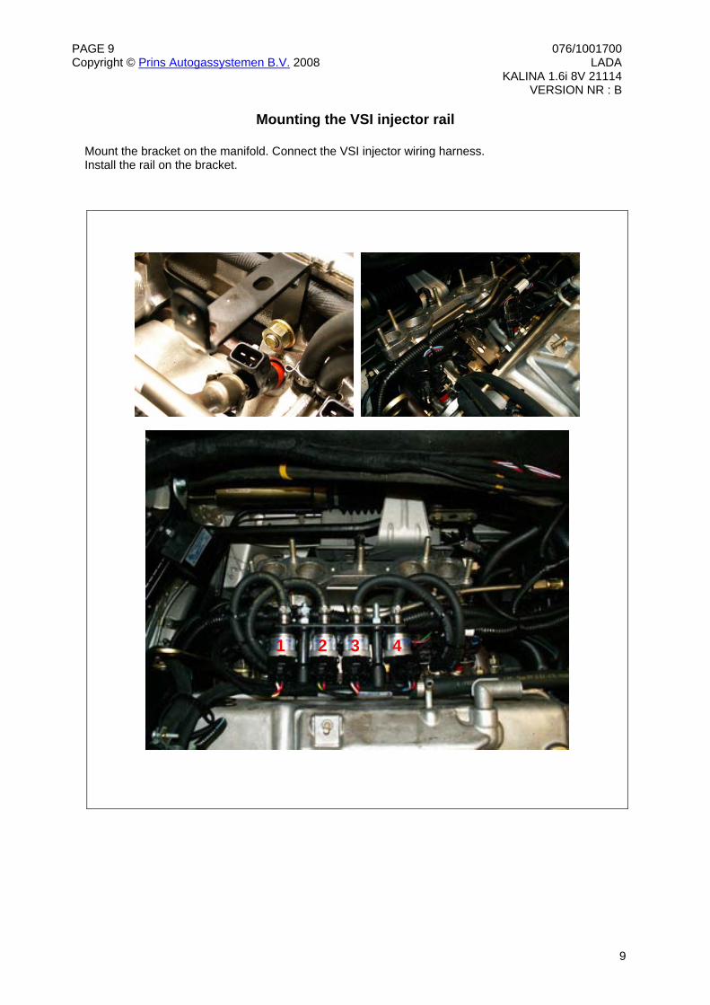
Mounting the VSI injector rail
Mount the bracket on the manifold. Connect the VSI injector wiring harness. Install the rail on the bracket.
1 2 3 4
PAGE 10 076/1001700Copyright © Prins Autogassystemen B.V. 2008 LADA KALINA 1.6i 8V 21114 VERSION NR : B
10
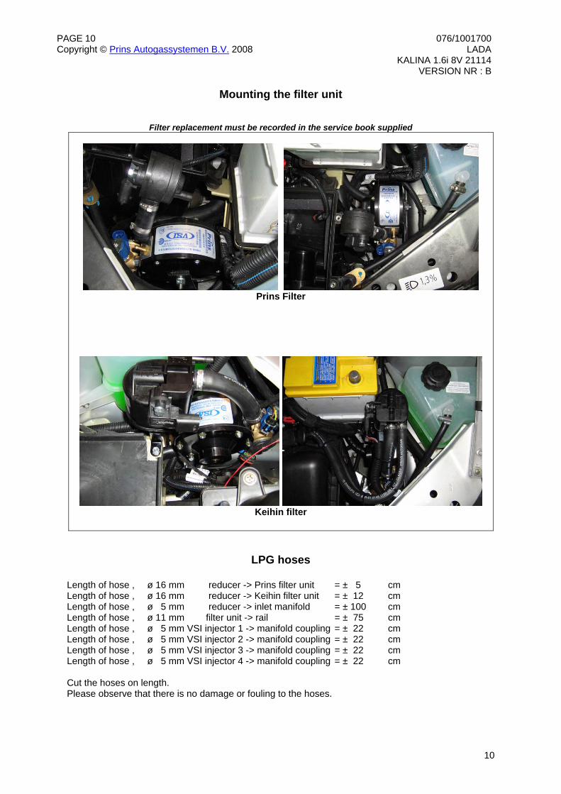
Mounting the filter unit
Filter replacement must be recorded in the service book supplied
Prins Filter
Keihin filter
LPG hoses Length of hose , ø 16 mm reducer -> Prins filter unit = ± 5 cm Length of hose , ø 16 mm reducer -> Keihin filter unit = ± 12 cm Length of hose , ø 5 mm reducer -> inlet manifold = ± 100 cm Length of hose , ø 11 mm filter unit -> rail = ± 75 cm Length of hose , ø 5 mm VSI injector 1 -> manifold coupling = ± 22 cm Length of hose , ø 5 mm VSI injector 2 -> manifold coupling = ± 22 cm Length of hose , ø 5 mm VSI injector 3 -> manifold coupling = ± 22 cm Length of hose , ø 5 mm VSI injector 4 -> manifold coupling = ± 22 cm Cut the hoses on length. Please observe that there is no damage or fouling to the hoses.
PAGE 11 076/1001700Copyright © Prins Autogassystemen B.V. 2008 LADA KALINA 1.6i 8V 21114 VERSION NR : B
11
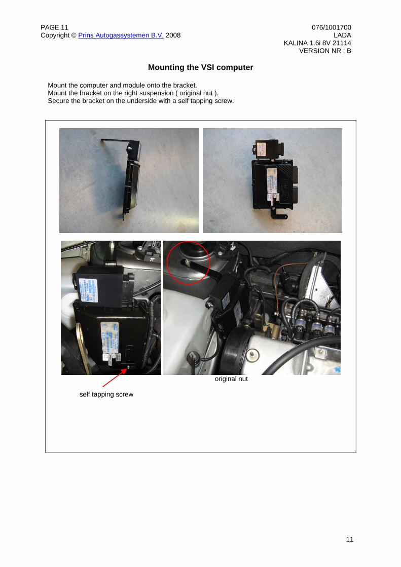
Mounting the VSI computer Mount the computer and module onto the bracket. Mount the bracket on the right suspension ( original nut ). Secure the bracket on the underside with a self tapping screw.
original nut
self tapping screw
PAGE 12 076/1001700Copyright © Prins Autogassystemen B.V. 2008 LADA KALINA 1.6i 8V 21114 VERSION NR : B
12
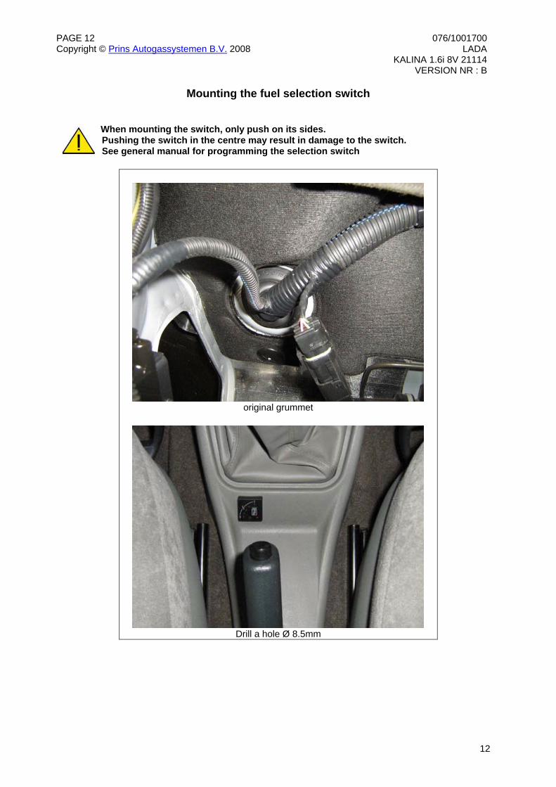
Mounting the fuel selection switch When mounting the switch, only push on its sides. Pushing the switch in the centre may result in damage to the switch. See general manual for programming the selection switch
original grummet
Drill a hole Ø 8.5mm
PAGE 13 076/1001700Copyright © Prins Autogassystemen B.V. 2008 LADA KALINA 1.6i 8V 21114 VERSION NR : B
13
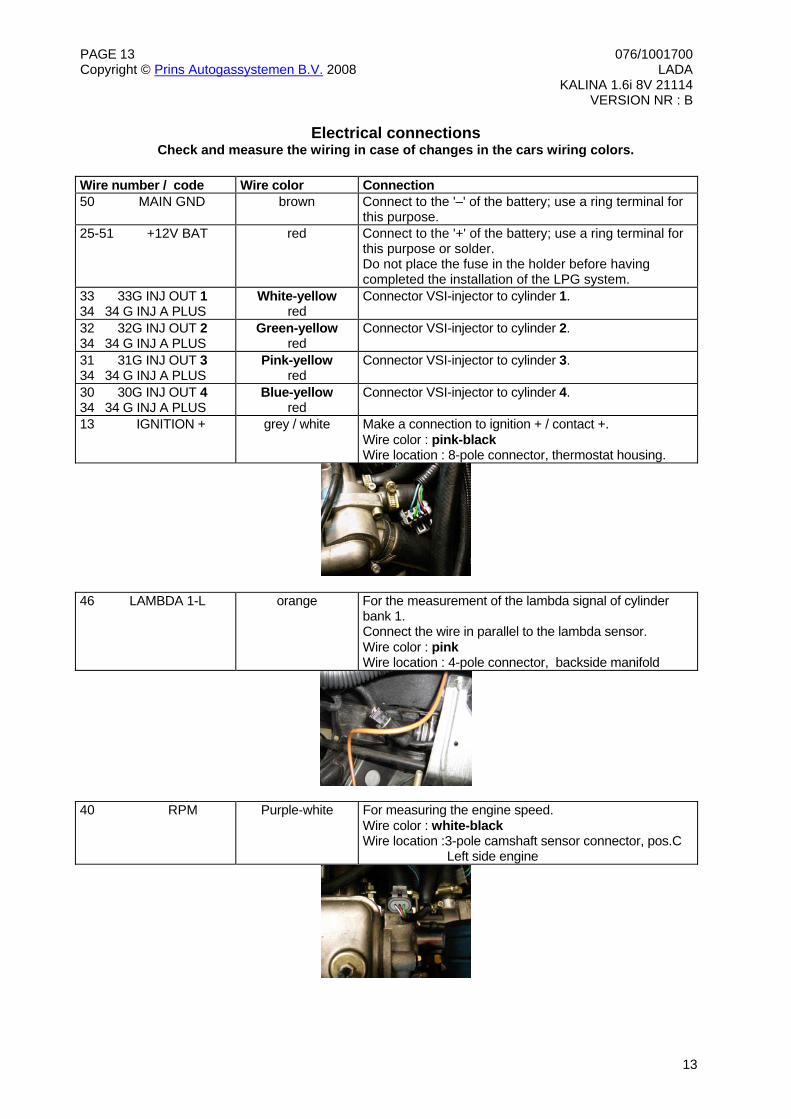
Electrical connections Check and measure the wiring in case of changes in the cars wiring colors.
Wire number / code Wire color Connection 50 MAIN GND brown Connect to the '–' of the battery; use a ring terminal for
this purpose. 25-51 +12V BAT red Connect to the '+' of the battery; use a ring terminal for
this purpose or solder. Do not place the fuse in the holder before having completed the installation of the LPG system.
33 33G INJ OUT 1 34 34 G INJ A PLUS
White-yellow red
Connector VSI-injector to cylinder 1.
32 32G INJ OUT 2 34 34 G INJ A PLUS
Green-yellow red
Connector VSI-injector to cylinder 2.
31 31G INJ OUT 3 34 34 G INJ A PLUS
Pink-yellow red
Connector VSI-injector to cylinder 3.
30 30G INJ OUT 4 34 34 G INJ A PLUS
Blue-yellow red
Connector VSI-injector to cylinder 4.
13 IGNITION + grey / white Make a connection to ignition + / contact +. Wire color : pink-black Wire location : 8-pole connector, thermostat housing.
46 LAMBDA 1-L orange For the measurement of the lambda signal of cylinder bank 1. Connect the wire in parallel to the lambda sensor. Wire color : pink Wire location : 4-pole connector, backside manifold
40 RPM Purple-white For measuring the engine speed. Wire color : white-black Wire location :3-pole camshaft sensor connector, pos.C Left side engine
PAGE 14 076/1001700Copyright © Prins Autogassystemen B.V. 2008 LADA KALINA 1.6i 8V 21114 VERSION NR : B
14
Electrical connections Check and measure the wiring in case of changes in the cars wiring colors.
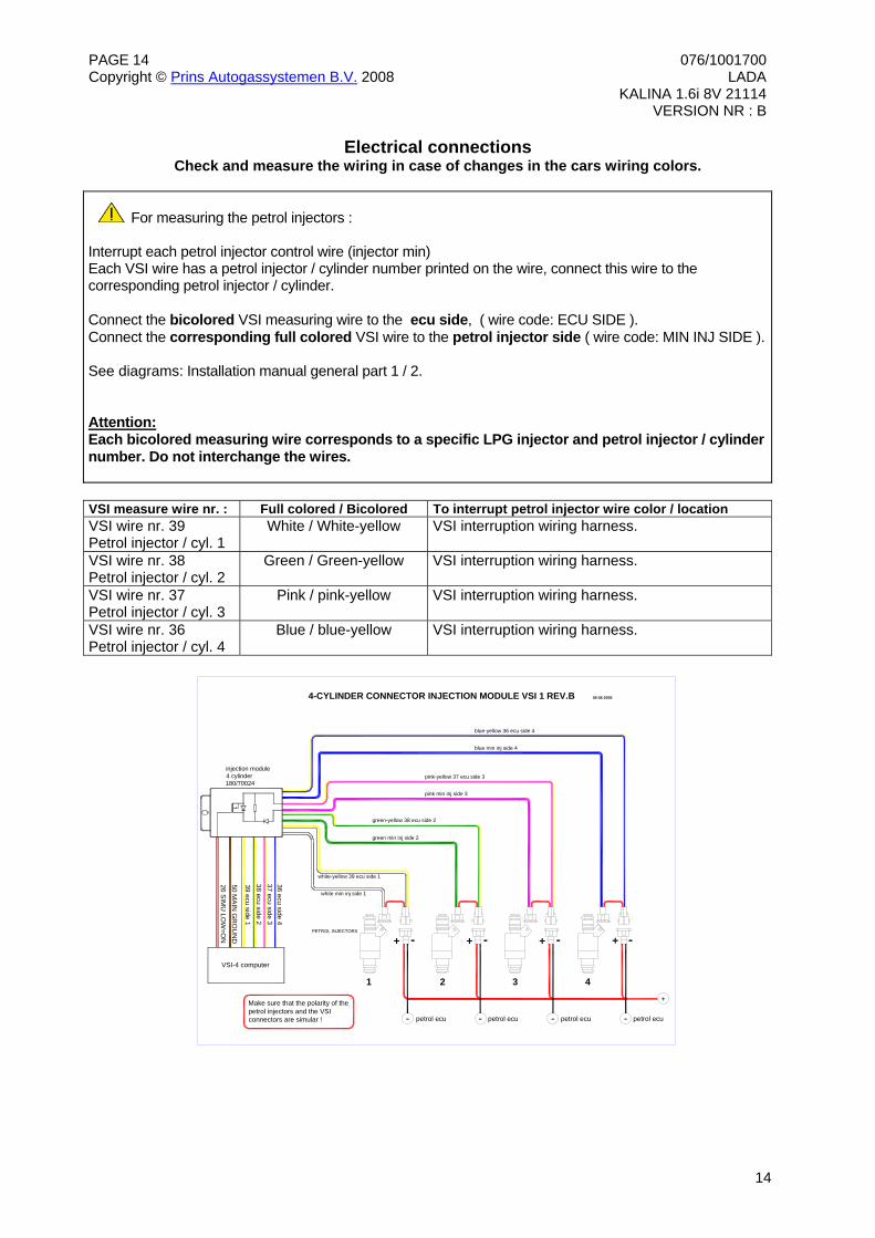
For measuring the petrol injectors : Interrupt each petrol injector control wire (injector min) Each VSI wire has a petrol injector / cylinder number printed on the wire, connect this wire to the corresponding petrol injector / cylinder. Connect the bicolored VSI measuring wire to the ecu side, ( wire code: ECU SIDE ). Connect the corresponding full colored VSI wire to the petrol injector side ( wire code: MIN INJ SIDE ). See diagrams: Installation manual general part 1 / 2. Attention: Each bicolored measuring wire corresponds to a specific LPG injector and petrol injector / cylinder number. Do not interchange the wires.
VSI measure wire nr. : Full colored / Bicolored To interrupt petrol injector wire color / location VSI wire nr. 39 Petrol injector / cyl. 1
White / White-yellow VSI interruption wiring harness.
VSI wire nr. 38 Petrol injector / cyl. 2
Green / Green-yellow VSI interruption wiring harness.
VSI wire nr. 37 Petrol injector / cyl. 3
Pink / pink-yellow VSI interruption wiring harness.
VSI wire nr. 36 Petrol injector / cyl. 4
Blue / blue-yellow VSI interruption wiring harness.
-
injection module4 cylinder180/70024
white min inj side 1
white-yellow 39 ecu side 1
+
36 ecu side 4
39 ecu side 138 ecu side 2
26 SIMU
LOW
=ON
50 MA
IN G
RO
UN
D
petrol ecu
4-CYLINDER CONNECTOR INJECTION MODULE VSI 1 REV.B 06-06-2005
green min inj side 2
green-yellow 38 ecu side 2
pink min inj side 3
pink-yellow 37 ecu side 3
blue min inj side 4
blue-yellow 36 ecu side 4
37 ecu side 3
VSI-4 computer
4
+ - + - + - + -
321
- - -petrol ecu petrol ecu petrol ecu
PETROL INJECTORS
Make sure that the polarity of the petrol injectors and the VSI connectors are simular !
PAGE 15 076/1001700Copyright © Prins Autogassystemen B.V. 2008 LADA KALINA 1.6i 8V 21114 VERSION NR : B
15
Checklist after installation 1. Connect the serial interface wire and run the VSI diagnosis program. Install the VSI mini fuse, and program the switch. Turn the ignition key in the accessory position. When working on the car, beware of moving and rotating parts in the engine compartment. 2. When commissioning the LPG system, you must activate the VSI computer with the diagnosis software. When the VSI computer has not been activated, it will keep generating error code 160. To activate the VSI computer, select function F11 (activate ECM). 3. Check whether the program in the VSI computer matches with the car ( dedicated engine set ):
Refer with F2 to the box number and car description in the diagnosis software and compare these with the set number.
4. The system will switch over to LPG as soon as the temperature of the coolant (T-ect) becomes higher than the parameter T-min set and when the TSO-cold time is expired. 5. Check all components and connections for any gas leakage ( use a LPG leak detector device or
a fluid detection like soap. Caution for moving and rotating parts in the engine compartment ! 6. Let the engine run warm on petrol >80°C. Check if the evaporator heats up. Check the engine signals, petrol injection time, RPM, ECT, lambda Let the engine run idle on LPG. Adjust the evaporator pressure. Refer to the parameter list ( or F2 : ID box) for the idle level value set. Adjust the evaporator pressure in such a way that the pressure measured ( P-sys ) equals the idle level value. Turn the socket-head screw at the front of the evaporator to adjust the pressure. An error code will be generated whenever the pressure variation is to high. Seal the evaporator with the sticker included in the delivery after having adjusted the pressure. 7. Use the diagnosis software to check again all input and output signals. 8. Check the system for error codes and solve these, if required. Check the petrol MMS for EOBD error codes. Place the protection connector on the VSI communication connector. 9. Make a test drive and check the drivability on LPG and petrol.
PAGE 16 076/1001700Copyright © Prins Autogassystemen B.V. 2008 LADA KALINA 1.6i 8V 21114 VERSION NR : B
16
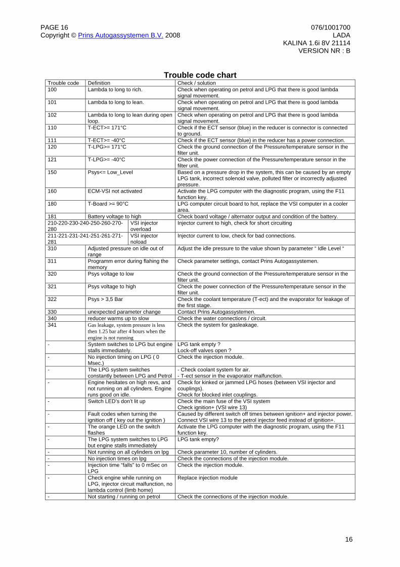
Trouble code chart
Trouble code Definition Check / solution 100 Lambda to long to rich. Check when operating on petrol and LPG that there is good lambda
signal movement. 101 Lambda to long to lean. Check when operating on petrol and LPG that there is good lambda
signal movement. 102 Lambda to long to lean during open
loop. Check when operating on petrol and LPG that there is good lambda signal movement.
110 T-ECT>= 171°C Check if the ECT sensor (blue) in the reducer is connector is connected to ground.
111 T-ECT>= -40°C Check if the ECT sensor (blue) in the reducer has a power connection. 120 T-LPG>= 171°C Check the ground connection of the Pressure/temperature sensor in the
filter unit. 121 T-LPG>= -40°C Check the power connection of the Pressure/temperature sensor in the
filter unit. 150 Psys<= Low_Level Based on a pressure drop in the system, this can be caused by an empty
LPG tank, incorrect solenoid valve, polluted filter or incorrectly adjusted pressure.
160 ECM-VSI not activated Activate the LPG computer with the diagnostic program, using the F11 function key.
180 T-Board >= 90°C LPG computer circuit board to hot, replace the VSI computer in a cooler area.
181 Battery voltage to high Check board voltage / alternator output and condition of the battery. 210-220-230-240-250-260-270-280
VSI injector overload
Injector current to high, check for short circuiting
211-221-231-241-251-261-271-281
VSI injector noload
Injector current to low, check for bad connections.
310 Adjusted pressure on idle out of range
Adjust the idle pressure to the value shown by parameter “ Idle Level “
311 Programm error during flahing the memory
Check parameter settings, contact Prins Autogassystemen.
320 Psys voltage to low Check the ground connection of the Pressure/temperature sensor in the filter unit.
321 Psys voltage to high Check the power connection of the Pressure/temperature sensor in the filter unit.
322 Psys > 3,5 Bar Check the coolant temperature (T-ect) and the evaporator for leakage of the first stage.
330 unexpected parameter change Contact Prins Autogassystemen. 340 reducer warms up to slow Check the water connections / circuit. 341 Gas leakage, system pressure is less
then 1.25 bar after 4 hours when the engine is not running
Check the system for gasleakage.
- System switches to LPG but engine stalls immediately.
LPG tank empty ? Lock-off valves open ?
- No injection timing on LPG ( 0 Msec.)
Check the injection module.
- The LPG system switches constantly between LPG and Petrol
- Check coolant system for air. - T-ect sensor in the evaporator malfunction.
- Engine hesitates on high revs, and not running on all cylinders. Engine runs good on idle.
Check for kinked or jammed LPG hoses (between VSI injector and couplings). Check for blocked inlet couplings.
- Switch LED’s don’t lit up Check the main fuse of the VSI system Check ignition+ (VSI wire 13)
- Fault codes when turning the ignition off ( key out the ignition )
Caused by different switch off times between ignition+ and injector power.Connect VSI wire 13 to the petrol injector feed instead of ignition+.
- The orange LED on the switch flashes
Activate the LPG computer with the diagnostic program, using the F11 function key.
- The LPG system switches to LPG but engine stalls immediately
LPG tank empty?
- Not running on all cylinders on lpg Check parameter 10, number of cylinders. - No injection times on lpg Check the connections of the injection module. - Injection time “falls” to 0 mSec on
LPG Check the injection module.
- Check engine while running on LPG, injector circuit malfunction, no lambda control (limb home)
Replace injection module
- Not starting / running on petrol Check the connections of the injection module.