Embed Size (px)
Citation preview
© 1
/20
07
Ste
inle
In
du
strie
pu
mp
en
Gm
bH
- B
roch
ure
Pis
ton
Dia
ph
rag
m P
um
ps
/ Ä
nd
eru
ng
en
vo
rbe
hal
ten
Pumps Designed for Filter Presses
Piston Diaphragm Pumps

© 1
/20
07
Ste
inle
In
du
strie
pu
mp
en
Gm
bH
- B
roch
ure
Pis
ton
Dia
ph
rag
m P
um
ps
/ Ä
nd
eru
ng
en
vo
rbe
hal
ten
Reliable
The treatment of the slurries by the filter-press is often a prerequisite for the smooth running of the whole production process. Therefore an absolutely safe and reliable pump is imperative.
High Pressure
The most important reason for choosing a STEINLE pump, besides its reliability, is the high transmission value of the inlet pressure to the outlet pressure. High pressure in the filter-press means a better filter result, lower costs for the removal of the filter cake and a shorter pressing process, together with opti-mal utilization of the equipment.
Ideal Pumping Properties
The liquid transferred to the filter-pressrequires exeptional high-performance pumps. They have to convey large quantities of liquid into the empty press as well as small quanti-ties at high pressure when the filter-press is filled. This pressure must be maintained for a long period of time.
Strong and Robust
In addition to the extremely high demandsplaced on its performance, the pump is often severaly stressed by the liquids. Most slurries are abrasive, shear-sensitive and sometimes they are also chemically aggressive.
– No dead-point possible
– No pressure load on the diaphragm
– Suitable for solvents
– Easy to check
– Provides dry filter-cake
– Suitable for solids
– long life time
The special design also generates
special properties:
– Dry running capability
– Self-priming
– Self-regulating 0...100%
– Easy to maintain
– Pressure up to 24 kg/cm²
– Low wear
– No shear
All STEINLE-pumps are self-regulating. This means, that no additional equipment is re-quired. When the filter press is full, the
pump just stops. For the single acting pumps sizes 15 and 25 a pulsation dampener in the discharge pipe is recommended.
The STEINLE Filter Press Pump
Properties
The Installation
Filter Press
Control Power Supply
Slurry Tank
CompressedAir Supply
Air Service Unit
Back Flow Pipe
PulsationDampener Pressure
Gauge
STEINLE-Pump
© 1
/20
07
Ste
inle
In
du
strie
pu
mp
en
Gm
bH
- B
roch
ure
Pis
ton
Dia
ph
rag
m P
um
ps
/ Ä
nd
eru
ng
en
vo
rbe
hal
ten
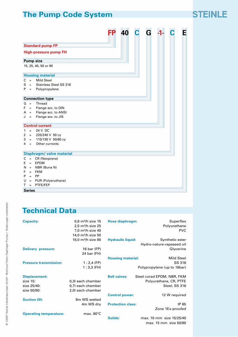
Capacity: 0,8 m³/h size 15 2,5 m³/h size 25 7,0 m³/h size 40 14,0 m³/h size 50 18,0 m³/h size 80
Delivery pressure: 16 bar (FP) 24 bar (FH)
Pressure transmission: 1 : 2,4 (FP) 1 : 3,3 (FH)
Displacement: size 15: 0,3l each chambersize 25/40: 0,7l each chamber size 50/80: 2,0l each chamber
Suction lift: 9m WS wetted 4m WS dry
Operating temperature: max. 80°C
Hose diaphragm: Superflex Polyurethane PVC
Hydraulic liquid: Synthetic ester Hydro-nature-rapeseed oil Glycerine
Housing material: Mild Steel SS 316 Polypropylene (up to 16bar)
Ball valves: Steel cored EPDM, NBR, FKM Polyurethane, CR, PTFE Steel, SS 316 Control power: 12 W required
Protection class: IP 65 Zone 1Ex-proofed
Solids: max. 10 mm size 15/25/40 max. 15 mm size 50/80
The Pump Code System
Technical Data
FP 40 C G -1- C E
Standard pump FP
High-pressure pump FH
Pump size15, 25, 40, 50 or 80
Housing materialC = Mild SteelS = Stainless Steel SS 316P = Polypropylene
Connection typeG = ThreadF = Flange acc. to DINA = Flange acc. to ANSIJ = Flange acc. to JIS
Control current1 = 24 V DC2 = 220/240 V 50 cy3 = 110/130 V 50/60 cy4 = Other currents
Diaphragm/ valve materialC = CR (Neoprene)E = EPDMN = NBR (Buna N)F = FKM P = PPU = PUR (Polyeruthane)T = PTFE/FEP
Series
© 1
/20
07
Ste
inle
In
du
strie
pu
mp
en
Gm
bH
- B
roch
ure
Pis
ton
Dia
ph
rag
m P
um
ps
/ Ä
nd
eru
ng
en
vo
rbe
hal
ten
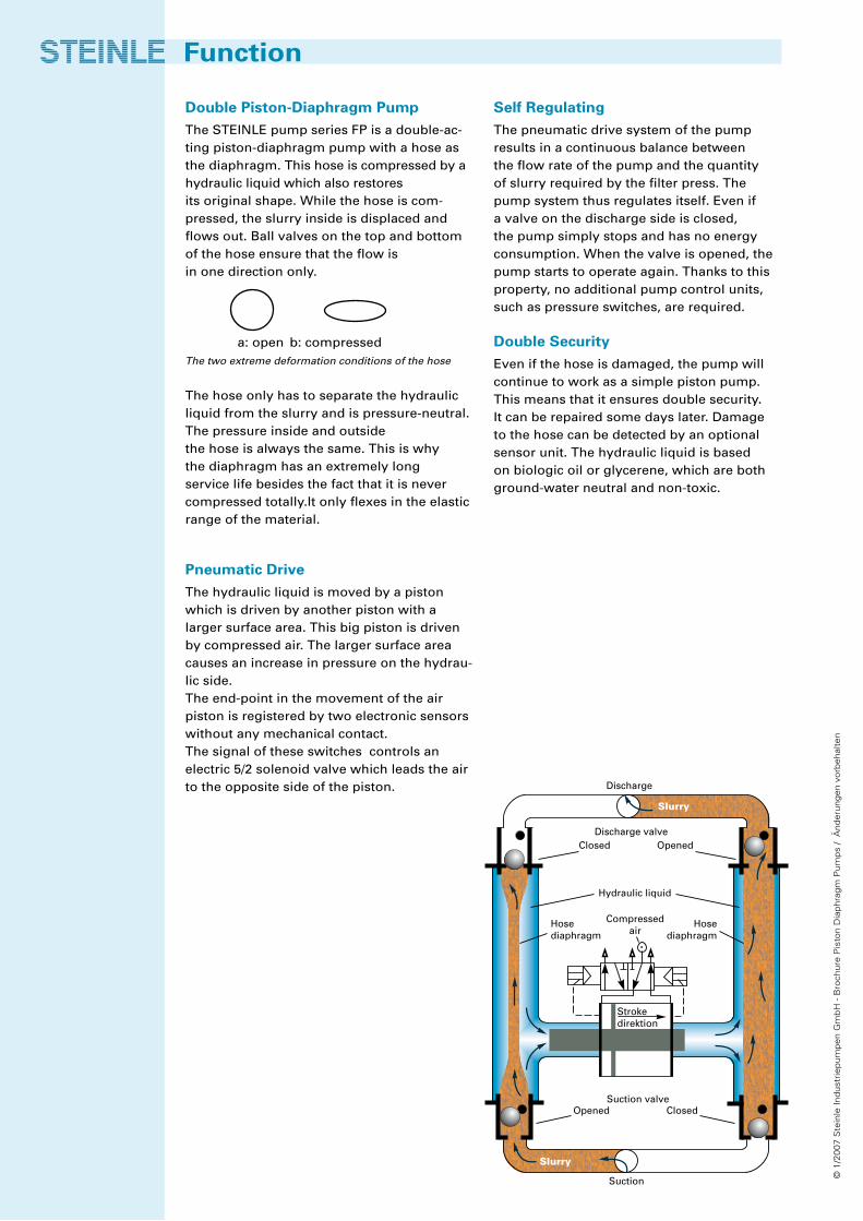
Self Regulating
The pneumatic drive system of the pump results in a continuous balance between the flow rate of the pump and the quantity of slurry required by the filter press. The pump system thus regulates itself. Even if a valve on the discharge side is closed, the pump simply stops and has no energy consumption. When the valve is opened, the pump starts to operate again. Thanks to this property, no additional pump control units, such as pressure switches, are required.
Double Security
Even if the hose is damaged, the pump will continue to work as a simple piston pump. This means that it ensures double security. It can be repaired some days later. Damage to the hose can be detected by an optional sensor unit. The hydraulic liquid is based on biologic oil or glycerene, which are both ground-water neutral and non-toxic.
Double Piston-Diaphragm Pump
The STEINLE pump series FP is a double-ac-ting piston-diaphragm pump with a hose as the diaphragm. This hose is compressed by a hydraulic liquid which also restores its original shape. While the hose is com-pressed, the slurry inside is displaced and flows out. Ball valves on the top and bottom of the hose ensure that the flow is in one direction only.
a: open b: compressedThe two extreme deformation conditions of the hose The hose only has to separate the hydraulic liquid from the slurry and is pressure-neutral. The pressure inside and outside the hose is always the same. This is why the diaphragm has an extremely long service life besides the fact that it is never compressed totally.It only flexes in the elastic range of the material.
Pneumatic Drive
The hydraulic liquid is moved by a piston which is driven by another piston with a larger surface area. This big piston is driven by compressed air. The larger surface area causes an increase in pressure on the hydrau-lic side. The end-point in the movement of the air piston is registered by two electronic sensors without any mechanical contact. The signal of these switches controls an electric 5/2 solenoid valve which leads the air to the opposite side of the piston.
Function
Strokedirektion
Discharge
Slurry
Discharge valve
Hydraulic liquid
Hosediaphragm
Hosediaphragm
Compressedair
Suction valveOpened Closed
OpenedClosed
Slurry
Suction
© 1
/20
07
Ste
inle
In
du
strie
pu
mp
en
Gm
bH
- B
roch
ure
Pis
ton
Dia
ph
rag
m P
um
ps
/ Ä
nd
eru
ng
en
vo
rbe
hal
ten
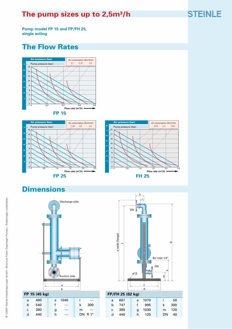
Pump model FP 15 and FP/FH 25, single acting
FP 15
FP 25 FH 25
The Flow Rates
Dimensions
The pump sizes up to 2,5m³/h
h
i
DN
Air inlet 1/4”
g
e (w
ith
fla
ng
e)
f
DN
mk
ø13
cd
Discharge side
Suction side
ab
Flow rate (m³/h)
Air pressure (bar)
Pump pressure (bar)
0 0,2 0,4 0,6 0,8
0,1 0,15 0,2
16
14
12
10
8
6
4
2
0
7
6
5
4
3
2
1
Air consumption (Nm³/min)
Air pressure (bar)
Pump pressure (bar)16
14
12
10
8
6
4
2
00 0,5 1,0 1,5 2, ,5
0,25 0,3 0,4
Flow rate (m³/h)
7
6
5
4
3
2
1
Air consumption (Nm³/min) Air pressure (bar)
Pump pressure (bar)
0 0,5 1,0 1,5 2, ,5
0,35 0,4 0,55
24
21
18
15
12
9
6
3
0
Flow rate (m³/h)
Air consumption (Nm³/min)
FP 15 (45 kg)
a 480 e 1040 i ---b 540 f --- k 300c 380 g --- m ---d 440 h --- DN R 1"
FP/FH 25 (62 kg)
a 687 e 1070 i 50b 747 f 995 k 300c 380 g 1030 m 120d 440 h 120 DN 40

© 1
/20
07
Ste
inle
In
du
strie
pu
mp
en
Gm
bH
- B
roch
ure
Pis
ton
Dia
ph
rag
m P
um
ps
/ Ä
nd
eru
ng
en
vo
rbe
hal
ten
The amounts given apply to water at 20°C, without suction lift. With higher-viscosity liquids and a suction lift, a reduction in the flow rate may result.
FP 40 FH 40
FP 50 FH 50
FP 80 FH 80
Air pressure (bar)
Pump pressure (bar)16
14
12
10
8
6
4
2
00 1 2 3 4 5
0,4 0,5 0,7
Flow rate (m³/h)
Air consumption (Nm³/min)
7
6
5
4
3
2
1
0 2 4 6 8 10 1 4
Flow rate (m³/h)
Air pressure (bar)
Pump pressure (bar)16
14
12
10
8
6
4
2
0
7
6
5
4
3
2
1
Air consumption (Nm³/min)
0,8 1,0 1,4
0 2 4 6 8 10 12 14 1 8
Flow rate (m³/h)
Air pressure (bar)
Pump pressure (bar)16
14
12
10
8
6
4
2
0
1,0 1,4 2,27
6
5
4
3
2
1
Air consumption (Nm³/min)
Air pressure (bar)
Pump pressure (bar)24
21
18
15
12
9
6
3
0
Flow rate (m³/h)2 3 4 5
0,55 0,7 1,0
Air consumption (Nm³/min)
0 2 4 6 8 10 1 4
Air pressure (bar)
Pump pressure (bar)24
21
18
15
12
9
6
3
0
Flow rate (m³/h)
Air consumption (Nm³/min)
1,1 1,5 2,1
Air pressure (bar)
Pump pressure (bar)24
21
18
15
12
9
6
3
0
Flow rate (m³/h)0 2 4 6 8 10 12 14 16 18
1,2 1,8 2,9
Air consumption (Nm³/min)
Example FP 40
With an existing pressure of 5 bar in com-pressed air supply, the pump delivers 3,5 m³/h at approximately 4 bar. Airconsumption will be 0,65 m³/min in this case, shown as standard m³.
Pump model FP/FH 40, 50 and 80,
double acting
The Flow Rates
The pump sizes up to 2,5 m³/h
© 1
/20
07
Ste
inle
In
du
strie
pu
mp
en
Gm
bH
- B
roch
ure
Pis
ton
Dia
ph
rag
m P
um
ps
/ Ä
nd
eru
ng
en
vo
rbe
hal
ten
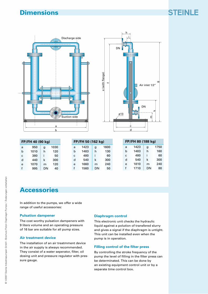
In addition to the pumps, we offer a wide range of useful accessories:
Pulsation dampener
The cost worthy pulsation dampeners with 9 liters volume and an operating pressure of 16 bar are suitable for all pump sizes.
Air treatment device
The installation of an air treatmment device in the air supply is always recommended. They consist of a water seperator, filter, oil dosing unit and pressure regulator with pres-sure gauge.
Diaphragm control
This electronic unit checks the hydraulic liquid against a polution of transfered slurry and gives a signal if the diaphragm is untight. This unit can be installed even when the pump is in operation.
Filling control of the filter press
By controlling the stroke frequency of the pump the level of filling in the filter press can be determinated. This can be done by an existing equipment control unit or by a separate time control box.
Dimensions
Accessories
h
i
DN
Air inlet 1/2”
g
e (w
ith
fla
ng
e)
fDN
mk
ø13
cd
Discharge side
Suction side
ab
FP/FH 40 (90 kg)
a 950 g 1030b 1010 h 120c 380 i 50d 440 k 300e 1070 m 120f 995 DN 40
FP/FH 80 (188 kg)
a 1423 g 1750b 1483 h 160c 480 i 60d 540 k 300e 1810 m 240f 1710 DN 80
FP/FH 50 (162 kg)
a 1423 g 1600b 1483 h 130c 480 i 60d 540 k 300e 1660 m 240f 1560 DN 50
© 1
/20
07
Ste
inle
In
du
strie
pu
mp
en
Gm
bH
- B
roch
ure
Pis
ton
Dia
ph
rag
m P
um
ps
/ Ä
nd
eru
ng
en
vo
rbe
hal
ten
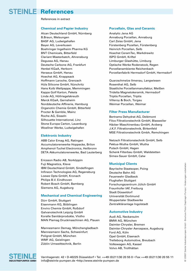
Porzellain, Glas and Ceramic
Analytic Jena AGAnnaburg Porzellan, Annaburg Carl Zeiss GmbH, Jena Fürstenberg Pozellan, Fürstenberg Heinrich Porzellan, Selb Hoechst CeramTec, Markdrewitz ISPO GmbH, Kriftel Limburger Glashütte, Limburg Optische Werke Rodenstock, Regen Porzellanambiente ReichenbachPorzellanfabrik Hermsdorf GmbH, Hermsdorf
Quarzschmelze Ilmenau, Langwiesen Rosenthal AG, Selb Staatliche Porzellanmanufaktur, Meißen Tridelta Magnetokeramik, Hermsdorf Triptis Porzellan, Triptis Villeroy & Boch, Torgau Weimar Porzellan, Weimar
Filter Press Manufacturer
Bertrams Dehydrat AG, Delémont Filox Filtrationstechnik GmbH, Blasweiler Häcker Maschinenbau GmbH, Arzberg J.K.F. Filtrationstechnik, Birkenfeld MSE Filtrationstechnik Gmbh, Remchingen
Netzsch Filtrationstechnik GmbH, Selb Pektus-Wutha GmbH, Wutha Putsch GmbH, Hagen Schenk Filterbau GmbH, Waldstetten Simex-Sauer GmbH, Calw
Municipal Clients
Bayrische Staatsoper, Poing Deutsche Bahn AG Feuerwehr Gladbeck Flughafen Stuttgart Forschungszentrum Jülich GmbHFraunhofer IAF, FreiburgStadt Düsseldorf Universität Dortmund Wuppertaler Stadtwerke Zentralkläranlage Ingolstadt
Automotive Industry
Audi AG, NeckarsulmBMW AG, MünchenDaimler-Chrysler, BremenDaimler-Chrysler Aerospace, AugsburgFord AG, KölnOpel GmbH, EisenachTrelleborg Automotive, BreubachVolkswagen AG, KasselVolvo AB, Trollhättan
Chemical and Papier Industry
Alcan Deutschland GmbH, Nürnberg B.Braun, Melsungen BASF AG, Ludwigshafen Bayer AG, Leverkusen Boehringer Ingelheim Pharma KGBNT Chemicals, BitterfeldClariant Masterbatch, AhrensburgDegussa AG, Hanau Deutsche Carbone AG, Frankfurt Henkel KGaA, Herborn Heraeus GmbH, Hanau Hoechst AG, Knappsack Hoffmann Laroche, Grenzach Hüls Silicone GmbH, Nünchritz Hans Kolb Wellpappe, MemmingenKappa Golf Karton, Pekela Linde AG, Höllriegelskreuth Merck KGaA, GernsheimNorddeutsche Affinerie, HamburgOrganotin Chemie GmbH, BitterfeldProcter & Gamble, Mainz Roche AG, Sisseln Silhouette International, Linz Stone Europa Carton, Lauenburg Woellner Werke, Ludwigshafen
Elektronic Industry
ABB Calor Emag AG, Ratingen Accumulatorenwerke Hoppecke, BrilonAmphenol-Tuchel Electronics, HeilbronnDETA Akkumulatorenwerke, Bad Lauterberg
Ericsson Radio AB, Norköppin Fuji Magnetics, KleveIBM Deutschland GmbH, Sindelfingen Infineon Technologies AG, RegensburgLoewe Opta GmbH, Kronach Philips B.V. Eindhoven Robert Bosch GmbH, Bamberg Siemens AG, Augsburg
Mechanical and Chemical Engineering
Dürr GmbH, Stuttgart Eisenmann KG, Böblingen Enviro Chemie GmbH, Roßdorf Galvanotechnik Leipzig GmbH Koralle Sanitärprodukte, Vlotho MAN Plamag Druckmaschinen AG, Plauen
Mannesmann Demag, Mönchengladbach Mannesmann Sachs, Schweinfurt Poligrat GmbH, München WMF AG, Geislingen Züblin Umwelttechnik, Berlin
References in extract
References
Varnhagenstr. 42 • D-40225 Düsseldorf • Tel. ++49 (0)211/30 20 55 0 • Fax ++49 (0)211/30 20 55 11 [email protected] •http://www.steinle-pumpen.de