Embed Size (px)
Citation preview
2013 Cervis, Inc.
Pistol Grip Application Tool
™
Customer Name: __________________________________________________ Contact Name: ____________________________________________________ Email:_____________________________ Phone: ______________________ Application Description / Machine Type: ______________________________ Date of Submission: ____/____/______ Revision: _______________________
™

PG Model Application Tool
Preferred selection in BOLD and UNDERLINED.
Thank you for considering Cervis, we look forward to working with you in your
application.
This tool is designed as a pre-sale document to aid in the communication and documentation of the application. The information presented in this document will be used for quoting purposes and therefore it is recommended to provide as much detail as possible
such that the following proposal reflects the total requirements as closely as possible. Should any questions arise during use of this document please contact Cervis’ sales
department at 724-741-9000. Thank you for considering Cervis, we look forward to working with you in your application.
PG Model Application Tool
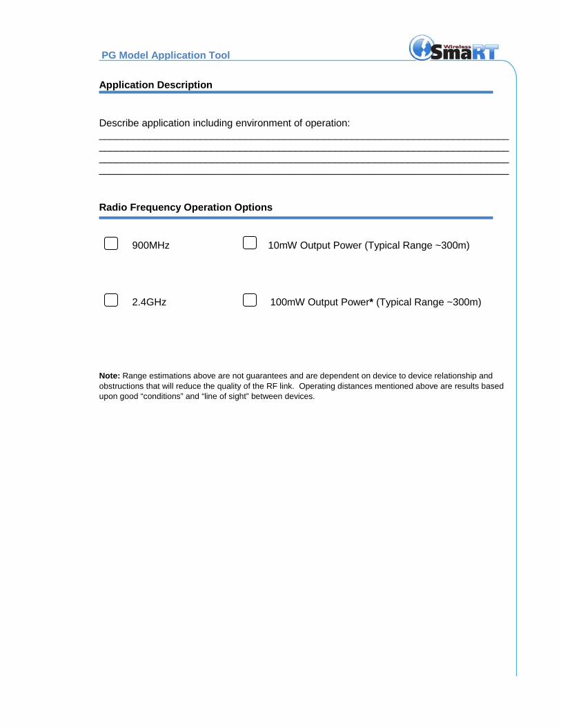
Application Description
Describe application including environment of operation: ___________________________________________________________________________________________________________________________________________________________________________________________________________________________ _________________________________________________________________________
Radio Frequency Operation Options
900MHz 10mW Output Power (Typical Range ~300m)
2.4GHz 100mW Output Power* (Typical Range ~300m)
Note: Range estimations above are not guarantees and are dependent on device to device relationship and obstructions that will reduce the quality of the RF link. Operating distances mentioned above are results based upon good “conditions” and “line of sight” between devices.
PG Model Application Tool
Preferred selection in BOLD and UNDERLINED.
Pistol Grip Design
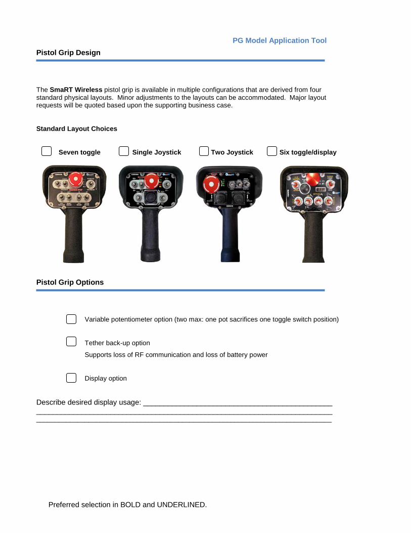
The SmaRT Wireless pistol grip is available in multiple configurations that are derived from four standard physical layouts. Minor adjustments to the layouts can be accommodated. Major layout requests will be quoted based upon the supporting business case.
Standard Layout Choices
Seven toggle Single Joystick Two Joystick Six toggle/display
Pistol Grip Options
Variable potentiometer option (two max: one pot sacrifices one toggle switch position)
Tether back-up option
Supports loss of RF communication and loss of battery power
Display option
Describe desired display usage: ______________________________________________ ________________________________________________________________________ _______________________________________________________________________________
3
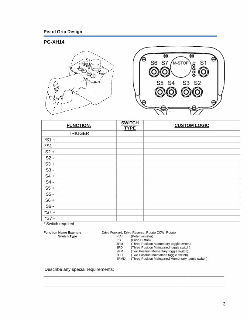
Pistol Grip Design
PG-XH14
FUNCTION: SWITCH TYPE CUSTOM LOGIC
TRIGGER *S1 + *S1 - S2 + S2 - S3 + S3 - S4 + S4 - S5 + S5 - S6 + S6 -
*S7 + *S7 -
* Switch required Function Name Example Drive Forward, Drive Reverse, Rotate CCW, Rotate Switch Type POT (Potentiometer) PB (Push Button) 3PM (Three Position Momentary toggle switch) 3PD (Three Position Maintained toggle switch) 2PM (Two Position Momentary toggle switch) 2PD (Two Position Maintained toggle switch) 3PMD (Three Position Maintained/Momentary toggle switch)
Describe any special requirements: ___________________________________________________________________________________________________________________________________________________________________________________________________________________________
PG Model Application Tool
Preferred selection in BOLD and UNDERLINED.
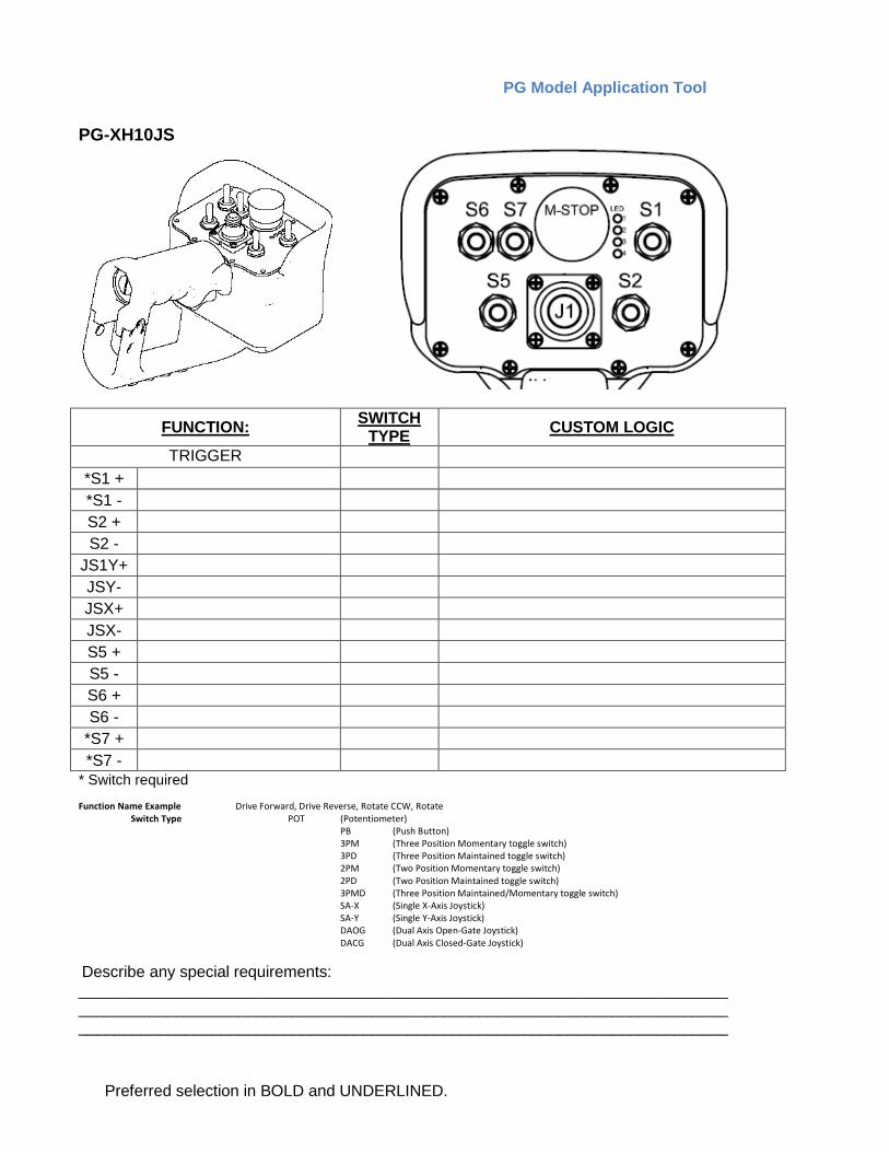
PG-XH10JS
FUNCTION: SWITCH TYPE CUSTOM LOGIC
TRIGGER *S1 + *S1 - S2 + S2 -
JS1Y+ JSY- JSX+ JSX- S5 + S5 - S6 + S6 -
*S7 + *S7 -
* Switch required Function Name Example Drive Forward, Drive Reverse, Rotate CCW, Rotate Switch Type POT (Potentiometer) PB (Push Button)
3PM (Three Position Momentary toggle switch) 3PD (Three Position Maintained toggle switch) 2PM (Two Position Momentary toggle switch) 2PD (Two Position Maintained toggle switch) 3PMD (Three Position Maintained/Momentary toggle switch) SA-X (Single X-Axis Joystick) SA-Y (Single Y-Axis Joystick) DAOG (Dual Axis Open-Gate Joystick) DACG (Dual Axis Closed-Gate Joystick)
Describe any special requirements: ___________________________________________________________________________________________________________________________________________________________________________________________________________________________
5
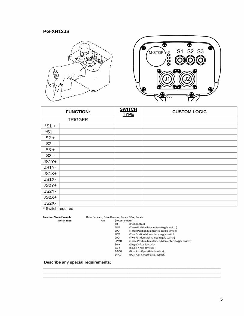
PG-XH12JS
FUNCTION: SWITCH TYPE CUSTOM LOGIC
TRIGGER *S1 + *S1 - S2 + S2 - S3 + S3 -
JS1Y+ JS1Y- JS1X+ JS1X- JS2Y+ JS2Y- JS2X+ JS2X- * Switch required Function Name Example Drive Forward, Drive Reverse, Rotate CCW, Rotate Switch Type POT (Potentiometer) PB (Push Button)
3PM (Three Position Momentary toggle switch) 3PD (Three Position Maintained toggle switch) 2PM (Two Position Momentary toggle switch) 2PD (Two Position Maintained toggle switch) 3PMD (Three Position Maintained/Momentary toggle switch) SA-X (Single X-Axis Joystick) SA-Y (Single Y-Axis Joystick) DAOG (Dual Axis Open-Gate Joystick) DACG (Dual Axis Closed-Gate Joystick)
Describe any special requirements: ________________________________________________________________________________________________________________________________________________________________________________________________________________________________________________
PG Model Application Tool
Preferred selection in BOLD and UNDERLINED.
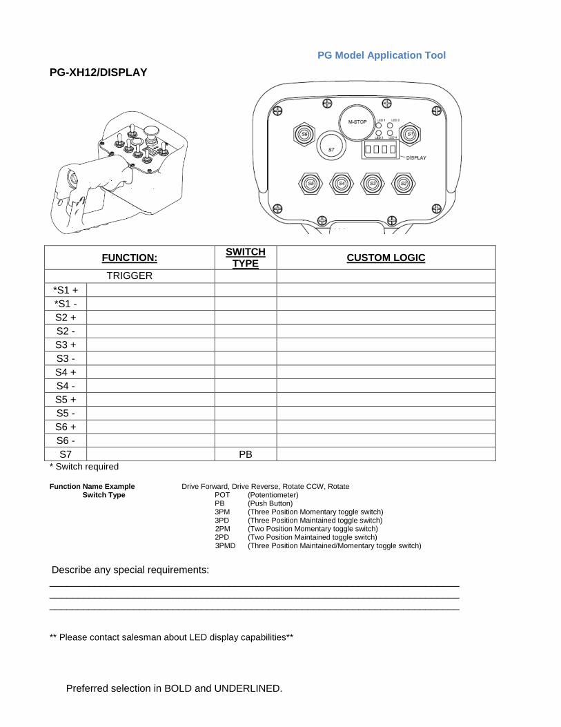
PG-XH12/DISPLAY
FUNCTION: SWITCH TYPE CUSTOM LOGIC
TRIGGER *S1 + *S1 - S2 + S2 - S3 + S3 - S4 + S4 - S5 + S5 - S6 + S6 - S7 PB
* Switch required Function Name Example Drive Forward, Drive Reverse, Rotate CCW, Rotate Switch Type POT (Potentiometer) PB (Push Button) 3PM (Three Position Momentary toggle switch) 3PD (Three Position Maintained toggle switch) 2PM (Two Position Momentary toggle switch) 2PD (Two Position Maintained toggle switch) 3PMD (Three Position Maintained/Momentary toggle switch)
Describe any special requirements: ___________________________________________________________________________________________________________________________________________________________________________________________________________________________
** Please contact salesman about LED display capabilities**
7
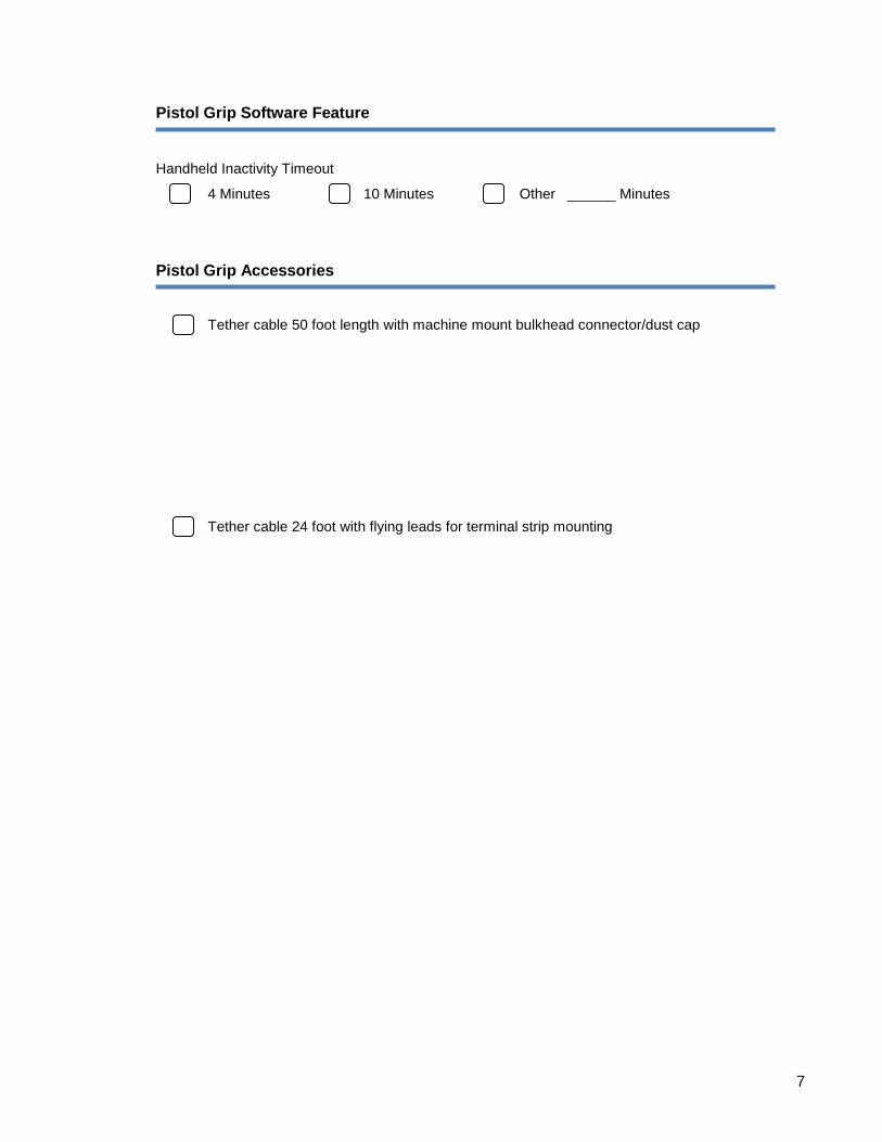
Pistol Grip Software Feature
Handheld Inactivity Timeout
4 Minutes 10 Minutes Other ______ Minutes
Pistol Grip Accessories
Tether cable 50 foot length with machine mount bulkhead connector/dust cap
Tether cable 24 foot with flying leads for terminal strip mounting
PG Model Application Tool
Preferred selection in BOLD and UNDERLINED.
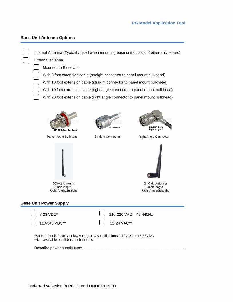
Base Unit Antenna Options
Internal Antenna (Typically used when mounting base unit outside of other enclosures)
External antenna
Mounted to Base Unit
With 3 foot extension cable (straight connector to panel mount bulkhead)
With 10 foot extension cable (straight connector to panel mount bulkhead)
With 10 foot extension cable (right angle connector to panel mount bulkhead)
With 20 foot extension cable (right angle connector to panel mount bulkhead)
Panel Mount Bulkhead Straight Connector Right Angle Connector
900Mz Antenna 2.4GHz Antenna 7 inch length 6 inch length
Right Angle/Straight Right Angle/Straight
Base Unit Power Supply 7-28 VDC* 110-220 VAC 47-440Hz 110-340 VDC** 12-24 VAC**
*Some models have split low voltage DC specifications 9-12VDC or 18-36VDC **Not available on all base unit models Describe power supply type: ________________________________________________
9
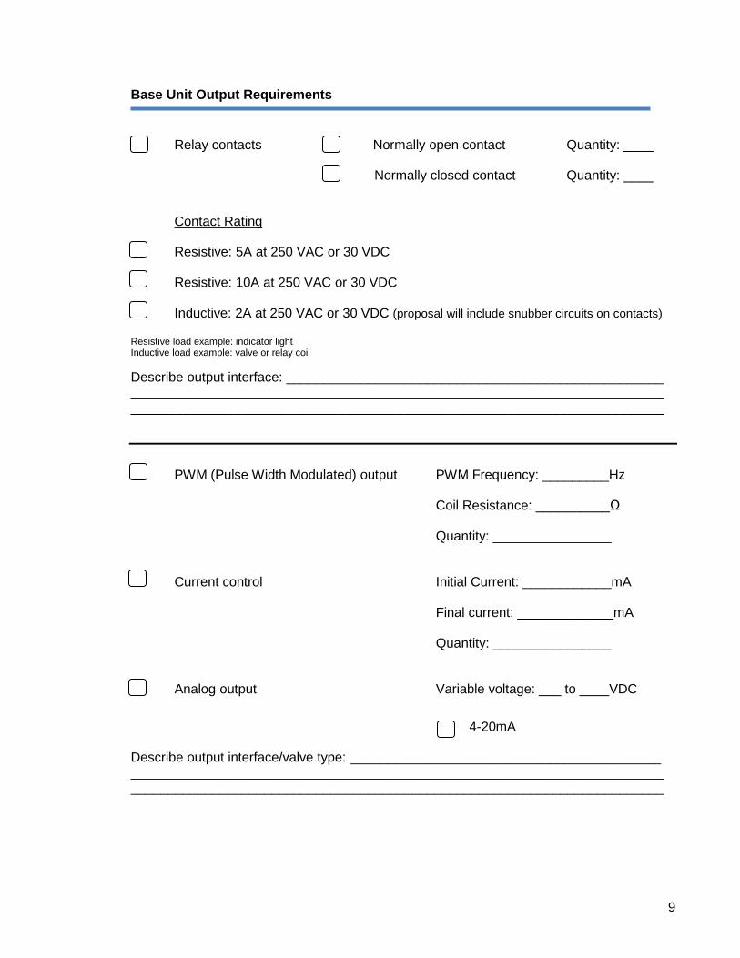
Base Unit Output Requirements
Relay contacts Normally open contact Quantity: ____ Normally closed contact Quantity: ____ Contact Rating
Resistive: 5A at 250 VAC or 30 VDC Resistive: 10A at 250 VAC or 30 VDC Inductive: 2A at 250 VAC or 30 VDC (proposal will include snubber circuits on contacts) Resistive load example: indicator light Inductive load example: valve or relay coil Describe output interface: ___________________________________________________ ________________________________________________________________________ ________________________________________________________________________ PWM (Pulse Width Modulated) output PWM Frequency: _________Hz Coil Resistance: __________Ω Quantity: ________________ Current control Initial Current: ____________mA Final current: _____________mA Quantity: ________________ Analog output Variable voltage: ___ to ____VDC 4-20mA Describe output interface/valve type: __________________________________________ ________________________________________________________________________ ________________________________________________________________________
PG Model Application Tool
Preferred selection in BOLD and UNDERLINED.
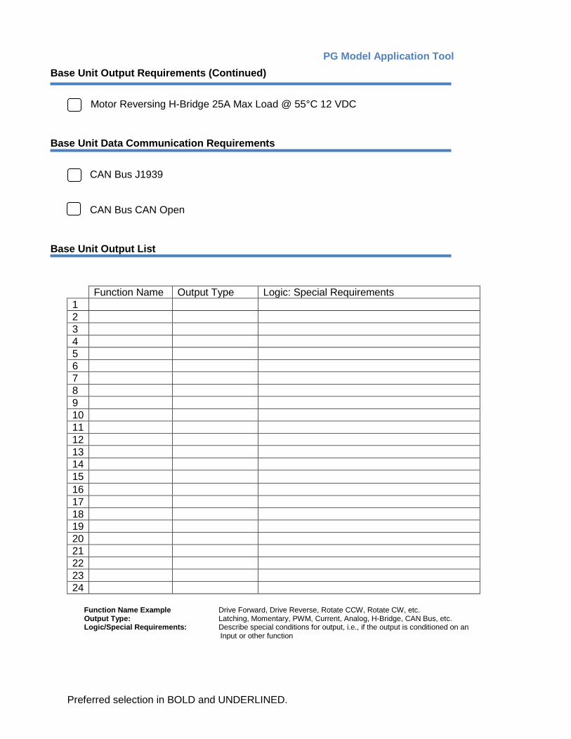
Base Unit Output Requirements (Continued)
Motor Reversing H-Bridge 25A Max Load @ 55°C 12 VDC Base Unit Data Communication Requirements
CAN Bus J1939 CAN Bus CAN Open Base Unit Output List
Function Name Output Type Logic: Special Requirements 1 2 3 4 5 6 7 8 9 10 11 12 13 14 15 16 17 18 19 20 21 22 23 24
Function Name Example Drive Forward, Drive Reverse, Rotate CCW, Rotate CW, etc. Output Type: Latching, Momentary, PWM, Current, Analog, H-Bridge, CAN Bus, etc. Logic/Special Requirements: Describe special conditions for output, i.e., if the output is conditioned on an
Input or other function
11
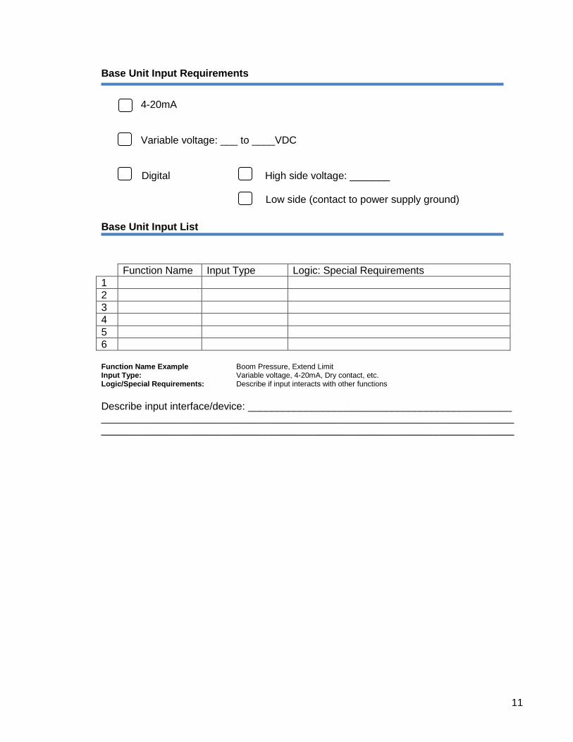
Base Unit Input Requirements
4-20mA Variable voltage: ___ to ____VDC Digital High side voltage: _______ Low side (contact to power supply ground) Base Unit Input List
Function Name Input Type Logic: Special Requirements 1 2 3 4 5 6 Function Name Example Boom Pressure, Extend Limit Input Type: Variable voltage, 4-20mA, Dry contact, etc. Logic/Special Requirements: Describe if input interacts with other functions Describe input interface/device: ______________________________________________ ________________________________________________________________________ ________________________________________________________________________
PG Model Application Tool
Preferred selection in BOLD and UNDERLINED.
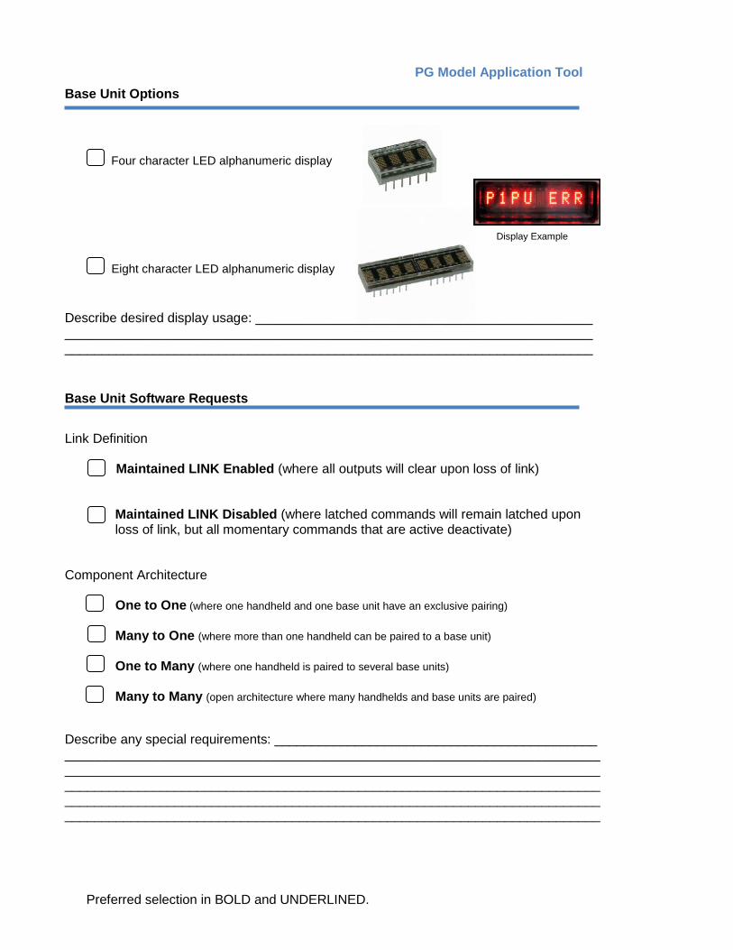
Base Unit Options
Four character LED alphanumeric display
Display Example Eight character LED alphanumeric display
Describe desired display usage: ______________________________________________ ________________________________________________________________________ ________________________________________________________________________ Base Unit Software Requests
Link Definition
Maintained LINK Enabled (where all outputs will clear upon loss of link)
Maintained LINK Disabled (where latched commands will remain latched upon loss of link, but all momentary commands that are active deactivate)
Component Architecture One to One (where one handheld and one base unit have an exclusive pairing) Many to One (where more than one handheld can be paired to a base unit) One to Many (where one handheld is paired to several base units) Many to Many (open architecture where many handhelds and base units are paired) Describe any special requirements: ____________________________________________ _____________________________________________________________________________________________________________________________________________________________________________________________________________________________________________________________________________________________________________________________________________________________________________
13
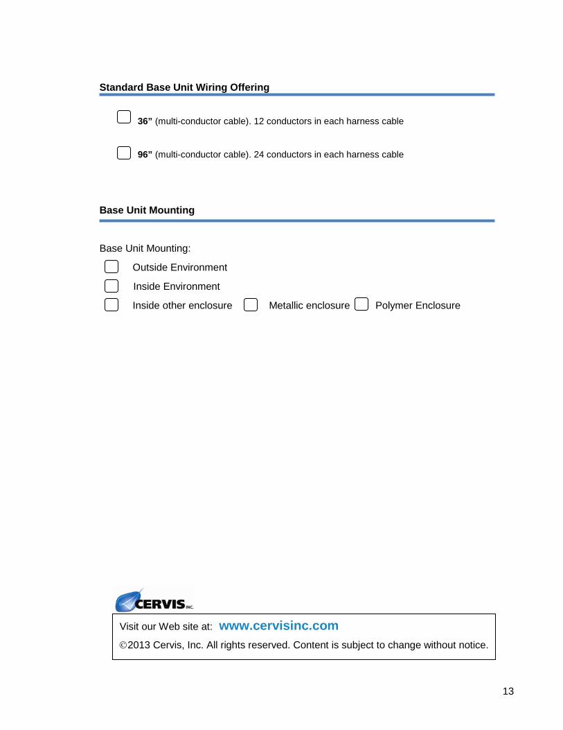
Standard Base Unit Wiring Offering
36” (multi-conductor cable). 12 conductors in each harness cable
96” (multi-conductor cable). 24 conductors in each harness cable
Base Unit Mounting
Base Unit Mounting:
Outside Environment
Inside Environment
Inside other enclosure Metallic enclosure Polymer Enclosure
Visit our Web site at: www.cervisinc.com
2013 Cervis, Inc. All rights reserved. Content is subject to change without notice.