Embed Size (px)
Citation preview

8/18/2019 Piping Users Guide
http://slidepdf.com/reader/full/piping-users-guide 1/187
PipingUser's Guide
Version 2011 (9.0) Service Pack 1
April 2011 / August 2011
DSP3D-PE-200025J-UPDATED

8/18/2019 Piping Users Guide
http://slidepdf.com/reader/full/piping-users-guide 2/187
Copyright
Copyright © 1999-2011 Intergraph Corporation. All Rights Reserved.
Including software, file formats, and audiovisual displays; may be used pursuant to applicable software license agreement;contains confidential and proprietary information of Intergraph and/or third parties which is protected by copyright law, trade secretlaw, and international treaty, and may not be provided or otherwise made available without proper authorization from IntergraphCorporation.
Portions of this software are owned by Spatial Corp. © 1986-2010. All Rights Reserved.
U.S. Government Restricted Rights Legend
Use, duplication, or disclosure by the government is subject to restrictions as set forth below. For civilian agencies: This wasdeveloped at private expense and is "restricted computer software" submitted with restricted rights in accordance withsubparagraphs (a) through (d) of the Commercial Computer Software - Restricted Rights clause at 52.227-19 of the Federal
Acquisition Regulations ("FAR") and its successors, and is unpublished and all rights are reserved under the copyright laws of theUnited States. For units of the Department of Defense ("DoD"): This is "commercial computer software" as defined at DFARS252.227-7014 and the rights of the Government are as specified at DFARS 227.7202-3.
Unpublished - rights reserved under the copyright laws of the United States.
Intergraph CorporationP.O. Box 240000Huntsville, AL 35813
Terms of Use
Use of this software product is subject to the End User License Agreement ("EULA") delivered with this software product unless thelicensee has a valid signed license for this software product with Intergraph Corporation. If the licensee has a valid signed license
for this software product with Intergraph Corporation, the valid signed license shall take precedence and govern the use of thissoftware product. Subject to the terms contained within the applicable license agreement, Intergraph Corporation gives licenseepermission to print a reasonable number of copies of the documentation as defined in the applicable license agreement anddelivered with the software product for licensee's internal, non-commercial use. The documentation may not be printed for resale orredistribution.
Warranties and Liabilities
All warranties given by Intergraph Corporation about equipment or software are set forth in the EULA provided with the software orapplicable license for the software product signed by Intergraph Corporation, and nothing stated in, or implied by, this document orits contents shall be considered or deemed a modification or amendment of such warranties. Intergraph believes the information inthis publication is accurate as of its publication date.
The information and the software discussed in this document are subject to change without notice and are subject to applicabletechnical product descriptions. Intergraph Corporation is not responsible for any error that may appear in this document.
The software discussed in this document is furnished under a license and may be used or copied only in accordance with the termsof this license. No responsibility is assumed by Intergraph for the use or reliability of software on equipment that is not supplied byIntergraph or its affiliated companies. THE USER OF THE SOFTWARE IS EXPECTED TO MAKE THE FINAL EVALUATION AS
TO THE USEFULNESS OF THE SOFTWARE IN HIS OWN ENVIRONMENT.Intergraph is not responsible for the accuracy of delivered data including, but not limited to, catalog, reference and symbol data.Users should verify for themselves that the data is accurate and suitable for their project work.
Trademarks
Intergraph, the Intergraph logo, PDS, SmartPlant, FrameWorks, I-Convert, I-Export, I-Sketch, SmartMarine, IntelliShip, INtools,ISOGEN, MARIAN, SmartSketch, SPOOLGEN, SupportManager, and SupportModeler are trademarks or registered trademarks ofIntergraph Corporation or its subsidiaries in the United States and other countries. Microsoft and Windows are registeredtrademarks of Microsoft Corporation. ACIS is a registered trademark of SPATIAL TECHNOLOGY, INC. Infragistics, PresentationLayer Framework, ActiveTreeView Ctrl, ProtoViewCtl, ActiveThreed Ctrl, ActiveListBar Ctrl, ActiveSplitter, ActiveToolbarsCtrl, ActiveToolbars Plus Ctrl, and ProtoView are trademarks of Infragistics, Inc. Incorporates portions of 2D DCM, 3D DCM, andHLM by Siemens Product Lifecycle Management Software III (GB) Ltd. All rights reserved. Gigasoft is a registered trademark, andProEssentials a trademark of Gigasoft, Inc. VideoSoft and VXFlexGrid are either registered trademarks or trademarks ofComponentOne LLC 1991-2009, All rights reserved. Oracle, JD Edwards, PeopleSoft, and Retek are registered trademarks ofOracle Corporation and/or its affiliates. Tribon is a trademark of AVEVA Group plc. Alma and act/cut are trademarks of the Almacompany. Other brands and product names are trademarks of their respective owners.

8/18/2019 Piping Users Guide
http://slidepdf.com/reader/full/piping-users-guide 3/187
Piping User's Guide 3
ContentsPreface .......................................................................................................................................................... 7
SmartPlant 3D Documentation Set ......................................................................................................... 7
Documentation Comments ..................................................................................................................... 9
What's New in Piping .................................................................................................................................. 9
Piping .......................................................................................................................................................... 11
Permission Groups and Routing ........................................................................................................... 14
Piping Workflow ........................................................................................................................................ 17
Piping Common Tasks .......................................................................................................................... 17
Create a Pipeline System ..................................................................................................................... 18
Create a Piping System ........................................................................................................................ 19
Piping in the Integrated Environment .................................................................................................... 19
Jacketed Piping ..................................................................................................................................... 23
Modeling Jacketed Piping .............................................................................................................. 23
Interference Checking .................................................................................................................... 33
Isometric Extraction ........................................................................................................................ 33
Orthographic Drawing Production .................................................................................................. 33
Route Pipe .................................................................................................................................................. 35
Create a new pipe run ........................................................................................................................... 46
Create an arc pipe run .......................................................................................................................... 47
Create a new pipe run from a P&ID run ................................................................................................ 47
Route pipe across P&ID off-page connectors ....................................................................................... 48
Place components while routing pipes ................................................................................................. 48
Place splits while routing pipes ............................................................................................................. 49
Route a sloped pipe run ........................................................................................................................ 49
Route a multi-sloped pipe run ............................................................................................................... 50
Route a pipe run to a specific coordinate location ................................................................................ 51
Route a pipe run at specified distance .................................................................................................. 51
Route a pipe run at specified distance and direction ............................................................................ 52
Route a branch at a specific angle........................................................................................................ 52
Route a pipe run with an offset ............................................................................................................. 53
Copy a pipe run ..................................................................................................................................... 53
Extend an existing pipe run ................................................................................................................... 54
Extend an existing arc pipe ................................................................................................................... 54
Merge pipe runs .................................................................................................................................... 54
Choose a working plane ....................................................................................................................... 56
Select pipe run settings ......................................................................................................................... 56
Change the flow direction of a pipe run ................................................................................................ 56
New Pipe Run Dialog Box ..................................................................................................................... 57
Defaults Tab (Route Pipe Settings Dialog Box) ............................................................................. 63
Set Offset Reference Dialog Box .......................................................................................................... 63
Specify Slope Direction Dialog Box ...................................................................................................... 65
Modify Slope Dialog Box ....................................................................................................................... 66

8/18/2019 Piping Users Guide
http://slidepdf.com/reader/full/piping-users-guide 4/187
Contents
4 Piping User's Guide
Select Pipe Run Dialog Box .................................................................................................................. 66
Select System Dialog Box ..................................................................................................................... 67
Insulation Specification Dialog Box ....................................................................................................... 67
Moving Pipe Features ............................................................................................................................... 69
Move a pipe run .................................................................................................................................... 72
Move a branch ...................................................................................................................................... 72
Move a sockolet, weldolet, or latrolet .................................................................................................... 72
Move a pipe end.................................................................................................................................... 73
Move a straight pipe .............................................................................................................................. 73
Move a turn ........................................................................................................................................... 74
Editing Properties ...................................................................................................................................... 75
Edit pipeline properties ......................................................................................................................... 76
Edit pipe run properties ......................................................................................................................... 77
Edit branch properties ........................................................................................................................... 77
Edit straight pipe properties .................................................................................................................. 77
Edit turn feature properties ................................................................................................................... 77
Edit part properties ................................................................................................................................ 78
Deleting Features ...................................................................................................................................... 79
Delete a branch ..................................................................................................................................... 80
Delete a straight pipe ............................................................................................................................ 80
Delete a component .............................................................................................................................. 80
Delete a split ......................................................................................................................................... 80
Delete a turn.......................................................................................................................................... 81
Delete a pipe run ................................................................................................................................... 81
Delete a pipeline ................................................................................................................................... 81
Insert Split .................................................................................................................................................. 83
Insert a welded split .............................................................................................................................. 85 Insert a takedown joint .......................................................................................................................... 85
Insert multiple splits a specified distance apart .................................................................................... 86
Insert a feature break ............................................................................................................................ 86
Edit split properties ............................................................................................................................... 86
Edit weld properties .............................................................................................................................. 87
Move a split ........................................................................................................................................... 87
Move a feature break ............................................................................................................................ 87
Pipe Split Feature Properties Dialog Box ............................................................................................. 87
General Tab (Pipe Split Feature Properties Dialog Box) ............................................................... 88
Insert Component ...................................................................................................................................... 91
Insert a component ............................................................................................................................... 95
Insert a component on a curved pipe ................................................................................................... 95 Insert a component while routing .......................................................................................................... 95
Insert an instrument .............................................................................................................................. 96
Insert a piping specialty item ................................................................................................................. 96
Insert a surface mounted component ................................................................................................... 96
Insert the default branch ....................................................................................................................... 97
Insert the default turn ............................................................................................................................ 97

8/18/2019 Piping Users Guide
http://slidepdf.com/reader/full/piping-users-guide 5/187
Contents
Piping User's Guide 5
Insert the default reducer ...................................................................................................................... 97
Place a tee from a P&ID ....................................................................................................................... 98
Place an elbolet..................................................................................................................................... 98
Select component settings .................................................................................................................... 98
Edit component properties .................................................................................................................... 99
Move a component ............................................................................................................................... 99
Rotate a component .............................................................................................................................. 99
Rotate a component on a nozzle .......................................................................................................... 99
Pipe Component Feature Properties Dialog Box ................................................................................ 100
General Tab (Pipe Component Feature Properties Dialog Box) .................................................. 100
Insert Tap.................................................................................................................................................. 103
Insert a tap .......................................................................................................................................... 105
Move a tap .......................................................................................................................................... 105
Rotate a tap ......................................................................................................................................... 105
Edit tap properties ............................................................................................................................... 105
Delete a tap ......................................................................................................................................... 105
Pipe Tap Feature Properties Dialog Box ............................................................................................ 106
Route Flex Pipe ........................................................................................................................................ 107
Route a flexible pipe ........................................................................................................................... 108
Route a flexible pipe from a P&ID run ................................................................................................ 108
Spooling ................................................................................................................................................... 109
Generate Spools ................................................................................................................................. 111
Create spools ............................................................................................................................... 111
Edit spool properties ..................................................................................................................... 112
Delete a spool ............................................................................................................................... 112
Spool Generation Dialog Box ....................................................................................................... 112
Spool Properties Dialog Box ........................................................................................................ 116
Create Penetration Spools .................................................................................................................. 116
Create penetration spools ............................................................................................................ 117
Generate Penetration Spools Dialog Box..................................................................................... 117
Penetration Spool Properties Dialog Box ..................................................................................... 119
Sequence Objects ................................................................................................................................... 121
Sequence weld names in a pipeline ................................................................................................... 123
Sequence weld names in a pipe run ................................................................................................... 123
Sequence weld names in a spool ....................................................................................................... 123
Sequence Weld Names in a WBS Item .............................................................................................. 123
Group Pipe Parts ..................................................................................................................................... 125
Grouping pipe parts by control points ................................................................................................. 125
Grouping pipe parts by query and control points ................................................................................ 126 Grouping pipe parts by query .............................................................................................................. 126
WBS Item Generation Dialog Box ....................................................................................................... 127
Options Tab (WBS Item Generation Dialog Box) ......................................................................... 127
Log Tab (WBS Item Generation Dialog Box) ............................................................................... 129

8/18/2019 Piping Users Guide
http://slidepdf.com/reader/full/piping-users-guide 6/187
Contents
6 Piping User's Guide
Appendix: Property Dialog Boxes ......................................................................................................... 131
Common Property Tabs ...................................................................................................................... 131
Configuration Tab ......................................................................................................................... 131
Connections Tab .......................................................................................................................... 132
Definition Tab ............................................................................................................................... 133
Notes Tab ..................................................................................................................................... 133
Occurrence Tab ............................................................................................................................ 134
Relationship Tab ........................................................................................................................... 136
Pipeline System Properties Dialog Box .............................................................................................. 136
General Tab (Pipeline System Properties Dialog Box) ................................................................ 137
Specifications Tab (Pipeline System Properties Dialog Box) ....................................................... 137
Default Property Values Tab (Pipeline System Properties Dialog Box) ....................................... 137
Pipe Run Properties Dialog Box ......................................................................................................... 141
General Tab (Pipe Run Properties Dialog Box) ........................................................................... 141
Pipe End Feature Properties Dialog Box ............................................................................................ 145
General Tab (Pipe End Feature Properties Dialog Box) .............................................................. 145
Pipe Straight Feature Properties Dialog Box ...................................................................................... 148
General Tab (Pipe Straight Feature Properties Dialog Box) ........................................................ 148
Pipe Surface Mount Feature Properties Dialog Box ........................................................................... 151
General Tab (Pipe Surface Mount Feature Properties Dialog Box) ............................................. 151
Pipe Turn Feature Properties Dialog Box ........................................................................................... 154
General Tab (Pipe Turn Feature Properties Dialog Box) ............................................................. 154
Pipe Part Properties Dialog Box ......................................................................................................... 157
Connection Properties Dialog Box ...................................................................................................... 157
General Tab (Connection Properties Dialog Box) ........................................................................ 157
Pipe Bolt Set Properties Dialog Box ................................................................................................... 158
Pipe Gasket Properties Dialog Box..................................................................................................... 158
Pipe Weld Properties Dialog Box ........................................................................................................ 158
General Tab (Pipe Weld Properties Dialog Box) .......................................................................... 158
Glossary ................................................................................................................................................... 161
Index ......................................................................................................................................................... 183

8/18/2019 Piping Users Guide
http://slidepdf.com/reader/full/piping-users-guide 7/187
Piping User's Guide 7
This document is a user's guide for the SmartPlant 3D Piping task and provides commandreference information and procedural instructions.
SmartPlant 3D Documentation SetSmartPlant 3D documentation is available as Adobe PDF files. The content is the same as onlineHelp. To access these PDF documents, click Help > Printable Guides in the software.
The documentation set is divided into four categories:
Administrative guides contain information about installing, configuring, customizing, andtroubleshooting SmartPlant 3D.
User's guides provide command reference and how-to information for working in eachSmartPlant 3D task.
Reference data guides define the reference data workbooks. Not all tasks have referencedata.
ISOGEN guides
Administrative Guides
SmartPlant 3D Installation Guide - Provides instructions on installing and configuring the software.
Project Management User's Guide - Provides instructions for setting up the databases, creatingpermission groups, backing up and restoring project data, assigning access permissions to themodel, defining and managing locations for Global Workshare, and version migration.
SmartPlant 3D Global Workshare Guide - Provides instructions for setting up the software and thedatabases to work in a workshare environment.
SmartPlant 3D Interference Checking Guide - Provides information on installing, configuring, andusing the interference detection service.
SmartPlant 3D Integration Reference Guide - Provides information about installing, configuring,and using SmartPlant 3D in an integrated environment.
SmartPlant 3D Interpreting Human Piping Specifications - Provides information about how tointerpret human piping specifications so that you can create the corresponding pipingspecification in the software.
SmartPlant 3D Export to PDMS - Provides information about how to export model data fromSmartPlant 3D to PDMS. Specific guidelines relating to best practices and known limitations of theexport functionality are also included.
SmartPlant 3D Point Cloud Reference - Provides information for referencing point cloud filesprovided by point cloud vendors in SmartPlant 3D.
SmartPlant 3D Troubleshooting Guide - Provides information on how to resolve errors that youmay encounter in the software by documenting troubleshooting tips, error messages, and to do list
messages.SmartPlant 3D Plant Design System (PDS) Guide - Provides all information needed to use PDSwith SmartPlant 3D. Topics include referencing active PDS projects in SmartPlant 3D, exportingPDS data and importing that data into SmartPlant 3D, and converting PDS reference data toSmartPlant 3D reference data.
SmartPlant 3D/SmartMarine 3D Programmer's Guide - Provides information about customcommands, naming rules, and symbol programming.
Preface

8/18/2019 Piping Users Guide
http://slidepdf.com/reader/full/piping-users-guide 8/187
Preface
8 Piping User's Guide
User's Guides
Catalog User's Guide - Provides information about viewing, editing, and creating reference dataand select lists (codelists).
Common User's Guide - Provides information about defining workspaces, manipulating views,and running reports.
Electrical User's Guide - Provides information about routing electrical cable, cableway, cable tray,and conduit.
Equipment and Furnishings User's Guide - Provides information about placing equipment.
Grids User's Guide - Provides instructions for creating coordinate systems, elevation grid planes,vertical grid planes, radial cylinders, radial planes, grid arcs, and grid lines.
Hangers and Supports User's Guide - Provides instructions on placing piping, duct, and cablewaysupports in the model.
HVAC User's Guide - Provides instructions for routing HVAC duct.
Orthographic Drawings User's Guide - Provides information about creating and managingorthographic drawings.
Piping Isometric Drawings User's Guide - Provides information about creating and managingpiping isometric drawings.
Piping User's Guide - Provides instructions for routing pipe and placing valves, taps, and pipe joints.
Reports User's Guide - Provides information about creating and managing spreadsheet reports.
Space Management User's Guide - Provides instructions for placing space objects such as areas,zones, interference volumes, and drawing volumes in the model.
Structural Analysis User's Guide - Provides instructions for defining loads, load cases, loadcombinations, and the importing and exporting of analytical data.
Structure User's Guide - Provides instructions for placing structural members such as: beams,columns, slabs, openings, stairs, ladders, equipment foundations, and handrails.
Systems and Specifications User's Guide - Provides instructions for creating systems andselecting which specifications are available for each system type.
Reference Data Guides
SmartPlant 3D 2D Symbols User's Guide - Provides command reference information andprocedural instructions for creating 2D symbols used to represent collars, clips, profiles, brackets,and other items.
SmartPlant 3D 2D Symbols Reference Data Guide - Provides information about thetwo-dimensional symbols used in all tasks.
Drawings and Reports Reference Data Guide - Provides information about reports reference data.
Electrical Reference Data Guide - Provides information about electrical cable, cableway, cabletray, and conduit reference data.
Electrical 3D Symbols Reference - Provides information about the cable tray and conduit 3Dsymbols that are available.
Equipment and Furnishings Reference Data Guide - Provides information about equipmentreference data.
Equipment 3D Symbols Reference - Provides information about the equipment, equipmentcomponent, design shapes, and design aides 3D symbols that are available.
Hangers and Supports Reference Data Guide - Provides information about hangers and supportsreference data.

8/18/2019 Piping Users Guide
http://slidepdf.com/reader/full/piping-users-guide 9/187
Preface
Piping User's Guide 9
Hangers and Supports 3D Symbols Reference - Provides information about the hanger andsupport 3D symbols that are available.
HVAC Reference Data Guide - Provides information about HVAC reference data.
HVAC 3D Symbols Reference - Provides information about the HVAC 3D symbols that areavailable.
SmartPlant 3D Reference Data Guide - Provides instructions about the Bulkload utility, codelists,and the reference data common to several disciplines.
Piping Reference Data Guide - Provides information about piping reference data including pipingspecifications, piping specification rules, piping parts, and piping symbols.
Piping 3D Symbols Reference - Provides information about the piping 3D symbols that areavailable.
Space Management Reference Data Guide - Provides information about space managementreference data.
Structure Reference Data Guide - Provides information about structural reference data.
Structure 3D Symbols Reference - Provides information about the stair, ladder, footings, andequipment foundation 3D symbols that are available.
ISOGEN GuidesSymbol Keys Reference Guide - Provides information about the symbol keys for isometricdrawings. This guide is from Alias, the makers of ISOGEN.
Documentation CommentsWe welcome comments or suggestions about this documentation. You can send us an email at:[email protected].
What's New in PipingThe following changes have been made to the Piping task.
Version 2011 (9.0) Service Pack 1
Using the Route Pipe (on page 35) command, you can opt to create an arc pipe run.
When inserting a component, you can now select mating ports or their associated ports whenspecifying a reference position. (P2 CP:166025)
Added information on moving a straight feature with terminus features. For more information,see Moving Pipe Features (on page 69). (P2 CP:118431)
When routing pipes by cardinal points, you can now specify whether the cardinal point is onthe actual pipe, or on the outside of the insulation. (P2 CP:96780)
A ribbon bar is now available for you to edit options corresponding to a surface mount pipecomponent in the model. (P2 CP:149495)
The Symbols share on the reference data server has been renamed SharedContent. Thisdocument has been updated to reflect this change.
The Sequence Objects ribbon contains a new option for starting a sequence ID. This optionis available only when Generate new numbers is selected. For more information, see"Sequence Objects Ribbon" in Sequence Objects (on page 121). (P2 CP:175071)
If you delete an existing spool, the sequencing task does not reuse the deleted sequence ID.(P2 CP:175120)

8/18/2019 Piping Users Guide
http://slidepdf.com/reader/full/piping-users-guide 10/187
Preface
10 Piping User's Guide
You can now place surface mounted components using their short codes from the InsertComponent command. For more information, see Insert a surface mounted component (onpage 96). (P2 CP:134557)
In the Insert Component command, if you select Specify component Tag for the Type, thedialog box now displays options to select the source for tags. For more information, see"Specify Component Tag Dialog Box" in Insert Component (on page 91). (CP:164757)
You can now define pipe run defaults at the pipeline level. For more information, see DefaultProperty Values Tab (Pipeline System Properties Dialog Box) (on page 137). Similarly, whencreating a new pipe run, you can select to load default properties from the piping system, thepipeline system, the existing pipe run (if you are extending an existing run), or to use thedefault properties that were used to place the last pipe run. For more information, see NewPipe Run Dialog Box (on page 57). (P3 CP:178555)
In the Arc Radius command, if you select Maintain Same Radius, you can route an arc pipewith same radius. You need not specify the center point every time you extend the arc. Formore information, see Extend an existing arc pipe (on page 54). (P2 CP:197580)

8/18/2019 Piping Users Guide
http://slidepdf.com/reader/full/piping-users-guide 11/187
Piping User's Guide 11
S E C T I O N 1
The Piping task is used to model distributed pipelines in your model using a point-by-point designmethod. Using the Piping task, you can create a fully rendered three- dimensional model of thevarious pipelines in your model. You also can use this task to insert piping components,instruments, and splits during design and then spool the pipe. You can start the Piping task byclicking Tasks > Piping.
Modeling of pipelines is aided by the piping specification, which limits and sometimesautomatically selects piping parts. Within a particular design context or pipeline service, thespecification author makes decisions in advance relating to both allowed parts and requirementsfor the parts that may be used in that service. Limiting the selection of parts through the use of apiping specification helps the designer by eliminating the need to make decisions related toapplicability, cost, procurement, and safety of particular parts within particular pipeline services.
Part selection is further aided through the provision of rules regarding the usage of particular types
of parts in particular design situations. The piping specification contains a grouping of pipingmaterials classes that define the requirements, characteristics, and behavior of the pipingcommodities for a specific service. For more information on the piping reference data and pipingspecifications, see the Piping Reference Data Guide or the Catalog Help.
Before you start modeling, there are some relationships and concepts that you need to know.
Piping Systems
Piping systems are a way of organizing pipelines in your model. You can create piping systemsbased on the area where the pipelines are located, by what the pipelines carry, by the pipingdesigner who models the pipelines, or by any other method that you choose. Piping systems are just a way to group objects. You create piping systems in the Systems and Specifications task.
PipelinesPipelines are a way of organizing pipe runs in your model and are created in the Systems andSpecifications task. You are not restricted to piping systems when creating pipelines. You cancreate pipelines under any previously created system. When you create a pipeline, you arerequired to define a fluid requirement and a fluid type.
Piping

8/18/2019 Piping Users Guide
http://slidepdf.com/reader/full/piping-users-guide 12/187
Piping
12 Piping User's Guide
Pipe Runs
A pipe run is a connected series of pipe features that normally have the same nominal pipingdiameter (NPD) and flow direction, and are normally governed by the same pipe specification. Allpipe features belong to a pipe run. One or more pipe runs make up a pipeline.
Pipe Features
When you route a pipe run, you place features defining high- level design information as you go.The software automatically selects the specific parts based on the pipe specification of the piperun. You may want to think of features as logical collections of parts driven by the pipespecification. There are several basic features: straight, turn, branch, end, run change, split, andalong leg component.
Pipe specifications are defined in the piping reference data. You can create and customizethe pipe specifications to suit your needs. See the Piping Reference Data Guide for moreinformation on defining pipe specifications.
8/18/2019 Piping Users Guide
http://slidepdf.com/reader/full/piping-users-guide 13/187
Piping
Piping User's Guide 13
Pipe Parts
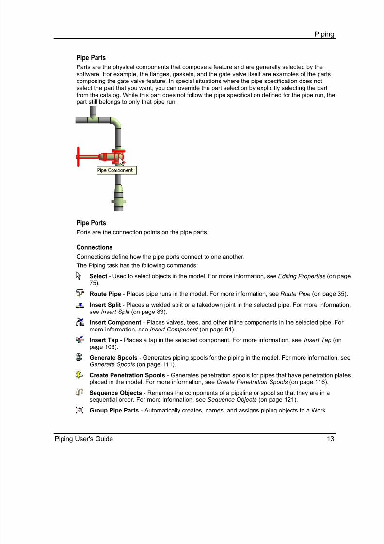
Parts are the physical components that compose a feature and are generally selected by thesoftware. For example, the flanges, gaskets, and the gate valve itself are examples of the partscomposing the gate valve feature. In special situations where the pipe specification does notselect the part that you want, you can override the part selection by explicitly selecting the partfrom the catalog. While this part does not follow the pipe specification defined for the pipe run, thepart still belongs to only that pipe run.
Pipe Ports
Ports are the connection points on the pipe parts.
Connections
Connections define how the pipe ports connect to one another.
The Piping task has the following commands:
Select - Used to select objects in the model. For more information, see Editing Properties (on page75).
Route Pipe - Places pipe runs in the model. For more information, see Route Pipe (on page 35).
Insert Split - Places a welded split or a takedown joint in the selected pipe. For more information,see Insert Split (on page 83).
Insert Component - Places valves, tees, and other inline components in the selected pipe. Formore information, see Insert Component (on page 91).
Insert Tap - Places a tap in the selected component. For more information, see Insert Tap (onpage 103).
Generate Spools - Generates piping spools for the piping in the model. For more information, seeGenerate Spools (on page 111).
Create Penetration Spools - Generates penetration spools for pipes that have penetration platesplaced in the model. For more information, see Create Penetration Spools (on page 116).
Sequence Objects - Renames the components of a pipeline or spool so that they are in asequential order. For more information, see Sequence Objects (on page 121).
Group Pipe Parts - Automatically creates, names, and assigns piping objects to a Work

8/18/2019 Piping Users Guide
http://slidepdf.com/reader/full/piping-users-guide 14/187
Piping
14 Piping User's Guide
Breakdown Structure (WBS) item. For more information, see Group Pipe Parts (on page 125).
Route Flex Pipe - Places flexible piping in the model. For more information, see Route Flex Pipe (on page 107).
See AlsoDeleting Features (on page 79) Moving Pipe Features (on page 69) Spooling (on page 109)
Permission Groups and RoutingSeveral different users in different permission groups can work together when routing if you knowhow the software handles the different situations. Starting in version 6.0, Piping fully supportsdifferent users, with different sets of privileges, working on different runs such as when working ina Global Workshare Configuration.
Prior to version 6.0, pipe route legs could be shared between pipe runs. In version 6.0 and later,
the software creates an Intermediate End Feature (IEF) at the end of a pipe run connected toanother pipe run and creates a logical connection between the two IEFs/runs. The legs stop at theIEF and are no longer shared between pipe runs. You do not need to create a separate permissiongroup for the pipe run and for the features of the pipe run. Everything can now be in the samepermission group.
Assignment of Permission Groups
The first thing to know is how permission groups are assigned:
Objects that you create directly are assigned to the active permission group.
Objects created automatically by the software are assigned a permission group determined byan internal set of rules. The permission group assigned is not necessarily the activepermission group. Examples of automatically placed objects include connections and a pipe
automatically inserted when two touching valves are separated. Parts generated by features are assigned the permission group of the parent feature.
Remember, however, that runs can be in a different permission group than its collectivefeatures and parts.
End features use the permission group of the run to which they belong.
Connections use the permission group of the parts to which they are connected. If theconnection is between parts with different permission groups, the permission group to whichthe user has write access is used. If the connection is between an equipment nozzle and aroute part, the route part permission group is used for the connection.
Piping connection objects (welds, bolt sets, gaskets, clamps) use the permission group of theconnection that generated it.
Systems and Permission Groups
A system is a logical grouping of sub-systems. When you add or remove a sub-system, you aremodifying the definition of the parent system. Therefore, you must have write access to the parentsystem. You do not need write access to the grandparent system. For example, to create a piperun, you need write access to the parent pipeline. However, you do not need access to the systemto which the pipeline belongs.
When participating in a Global Workshare Configuration, you must manage all permission groupsat the host site. The sub- system requirement to have write access to its parent system is not

8/18/2019 Piping Users Guide
http://slidepdf.com/reader/full/piping-users-guide 15/187

8/18/2019 Piping Users Guide
http://slidepdf.com/reader/full/piping-users-guide 16/187
Piping
16 Piping User's Guide
John creates an initial header run using PG-John as the active permission group and routes it asneeded. Peter now wants to branch from John's run. Peter sets PG-Peter as the active permissiongroup and selects the header in John's run from which to branch. Instead of creating the headercomponent (such as a tee), the software generates a To Do List item for John.
When John updates the out-of-date To Do List item, the software modifies the header to add thetee, then generates a To Do List item for Peter.
When Peter updates his out-of-date To Do List item, the software fixes the branch leg (the end ofthe branch leg is adjusted to the tee port). This is called a double hand-shaking mechanism.

8/18/2019 Piping Users Guide
http://slidepdf.com/reader/full/piping-users-guide 17/187
Piping User's Guide 17
S E C T I O N 2
All piping elements are placed in the model using information defined in the piping reference data.Using the Catalog task or the reference data workbooks, you can create custom pipespecifications, edit pipe specification rules, and define pipe parts and symbols. Your first stepshould be to review, edit, and otherwise customize the delivered piping reference data. Refer tothe Piping Reference Data Guide or the Catalog Help for more information.
After the reference data is customized to suit your needs, you need to define piping systems andpipelines in the Systems and Specifications task. You cannot place pipe runs in the model until thepipelines are defined.
After the piping reference data and the needed systems are defined, you can begin placing pipe inyour model.
After pipe is in your model, the Piping task enables you to spool pipe into sections ready formanufacturing. To create penetration spools, at least one penetration plate must exist in themodel. You can place penetration plates in the Hangers and Supports task.
See AlsoPiping Common Tasks (on page 17) Piping (on page 11) Piping in the Integrated Environment (on page 19)
Piping Common TasksThe following tasks are used frequently in the piping task.
Customize Reference Data
Create custom pipe specifications. Define parts and symbols. For more information on creating symbols, see SmartPlant 3D
Symbols Reference Data Guide.
Create Needed Systems
Create new pipe systems. For more information, see Create a piping system (on page 19).
Create new pipelines. For more information, see Create a pipeline system (on page 18).
Route Pipe Runs
Route new pipe runs in the pipelines that you defined. For more information, see Create a new pipe run (on page 46).
Insert Splits, Components, and Taps Insert pipe splits in the pipe runs to create the needed spools lengths. You can insert splits
while routing the pipe runs or after the runs are in the model. For more information, see Placesplits while routing pipes (on page 49), Insert a takedown joint (on page 85), and Insert awelded split (on page 85).
Piping Workflow

8/18/2019 Piping Users Guide
http://slidepdf.com/reader/full/piping-users-guide 18/187
Piping Workflow
18 Piping User's Guide
Insert valves, reducers, tees, and other components. You can insert components while routingthe pipe runs or after the runs are in the model. For more information, see Place componentswhile routing pipes (on page 48) and Insert a component (on page 95).
Insert ports on components for venting, drainage, and for the connection of other componentssuch as instruments. For more information, see Insert a tap (on page 105).
Create Piping Spools
Split the pipe into spools by using the Generate Spools or Create Penetration Spools commands. For more information, see Create spools (on page 111) and Create penetrationspools (on page 117).
Create a Pipeline SystemIn the Systems and Specifications task:
1. Click Task > Systems and Specifications.
2. In the tree, select the system in which you want to create the pipeline system.
3. From the ribbon, select New Pipeline System .
4. Type a description for the pipeline system.
5. Specify a fluid requirement and fluid type for the pipeline.
6. Click OK.
7. Select the new pipeline system in the tree, and then right-click and select Properties.
8. Change any properties of the system as needed.
In the Piping task:
1. Click Select on the vertical toolbar.
2. Select All in the Locate Filter .
3. In the Workspace Explorer, right-click on the parent to the pipeline system that you arecreating.
4. Click New System > New Pipeline on the pop-up menu.
5. Type a description for the pipeline system.
6. Specify a fluid requirement and fluid type for the pipeline.
7. Click OK.
8. Right-click on the new pipeline system in the Workspace Explorer, and then selectProperties.
9. Change any additional properties as needed.

8/18/2019 Piping Users Guide
http://slidepdf.com/reader/full/piping-users-guide 19/187
Piping Workflow
Piping User's Guide 19
Create a Piping SystemIn the Systems and Specifications task:
1. Click Task > Systems and Specifications.
2. In the tree, select the system in which you want to create the piping system.
3. From the ribbon, select New Piping System .
4. Select the new system in the tree, and then right-click and select Properties.
5. Change any properties of the system as needed.
In the Piping task:
1. Click Select on the vertical toolbar.
2. Select All in the Locate Filter .
3. In the Workspace Explorer, right-click on the parent to the piping system that you are creating.
4. Click New System > New Piping System on the pop-up menu.
5. Right-click on the new piping system in the Workspace Explorer, and then select Properties.
6. Change any additional properties as needed.
Piping in the Integrated EnvironmentThis section describes how to use the Piping task in a SmartPlant integrated environment. Formore information, refer to the SmartPlant 3D Integration Reference Guide available from the Help> Printable Guides command.
Piping Catalog Data
SmartPlant P&ID and SmartPlant 3D must use the same naming convention for pipingcomponents and equipment for proper correlation in an integrated environment. For example,piping reducers Catalog data must be changed. Specifically, all pipe specification reducercomponents must have the name "Concentric Reducer" instead of the default name "ConcentricSize Change". You can either edit the existing catalog spreadsheet entries or copy the existingentries and add new entries as shown below. Then Bulkload this spreadsheet into the Catalog.
Correlating Pipe Runs
Existing pipe runs in the model that you want to correlate to P&ID data must be reassigned to thepiping system that you want to correlate to. You cannot correlate the pipe run until it is moved. After it is in the correct piping system, you can correlate existing pipe runs by:
1. Select SmartPlant > Correlate with Design Basis.

8/18/2019 Piping Users Guide
http://slidepdf.com/reader/full/piping-users-guide 20/187
Piping Workflow
20 Piping User's Guide
2. Select the pipe run in the model.
3. Select the P&ID that contains the pipe run, and then click Open.
4. Select the pipe run in the P&ID.
5. Review any data mismatch between the P&ID pipe run and the model pipe run. Fix the data asappropriate.
6. Click Update.
Previously correlated pipe runs (displayed as green in the P&ID) that change color to red or blue inthe P&ID on subsequent retrieval of a new revision of the P&ID data need to be updated asfollows:
1. Set the Locate Filter to Piping Runs.
2. Select the run in either the model or the P&ID.
3. Select SmartPlant > Compare to Design Basis.
4. Any data item that has changed is highlighted in red.
5. Click Update.
When you click Update, any in-line component is also updated if it is still a valid piping
component and if the component symbol still exists on the pipe run. If the symbol has beendeleted, you will need to delete this component.
In-line components placed with the use of dimensional data from SmartPlant Instrumentationmust be updated in a separate process.
Correlating Instruments
You can correlate existing instruments in the model by:
1. Select SmartPlant > Correlate with Design Basis.
2. Select the modeled instrument.
3. Select the P&ID that contains the instrument, and then click Open.
4. Select the instrument in the P&ID.
5. Review any data mismatches between the P&ID instrument and the modeled instrument. Fixthe data as appropriate.
6. Click Update.
You can place new correlated instruments using existing SmartPlant 3D Catalog instrumentcomponents or using the automatic creation of the instrument from the dimensional data suppliedby SmartPlant Instrumentation.
To place standard Catalog instruments, you must manually match the instrument to place with thetype of instrument called-out in the P&ID:
1. Route the pipe run from the P&ID. For detailed steps, see Create a New Pipe Run from aP&ID Run (on page 47).
2. Select SmartPlant > View P&ID.
3. Select the P&ID that contains the instrument to place, and then click Open.
4. Click Insert Component on the vertical toolbar.
5. Select the area of the pipe run to place the instrument.
6. Select the component in the P&ID view.
7. In the Type option on the ribbon, select <Specify Component Tag>.
8. Select Browse instruments.
9. Select the proper instrument as indicated on the P&ID.

8/18/2019 Piping Users Guide
http://slidepdf.com/reader/full/piping-users-guide 21/187
Piping Workflow
Piping User's Guide 21
10. Position the instrument, and click Finish.
11. Open the properties for the instrument and size it appropriately for the pipe run.
To place instruments built on the fly from the dimensional data sheet data published fromSmartPlant Instrumentation, SmartPlant 3D reads the dimensional data sheet, applies thosevalues to the instrument in the background, and then places the instrument on the pipe feature.
When retrieving from a P&ID:1. Route the pipe run from the P&ID. For detailed steps, see Create a New Pipe Run from a
P&ID Run (on page 47).
2. Select SmartPlant > View P&ID.
3. Select the P&ID that contains the instrument to place, and then click Open.
4. Click Insert Component on the vertical toolbar.
5. Select the instrument in the P&ID.
6. Position the instrument on the pipe run, and then click Finish.
When retrieving directly from Dimensional Data Sheet information:
1. Click Insert Component on the vertical toolbar.
2. In the Type box on the ribbon, select Specify Component Tag.
3. Type in the component tag.
4. If found, the software will create and correlate the component as it would if the componentwere selected from a P&ID.
Only those instruments that were built from dimensional data sheets or have had a name changerequire updating.
To update instruments built/placed from dimensional data sheets:
1. Retrieve the new DDP.
2. Select the instrument in the model.
3. Select SmartPlant > Compare to Design Basis.
4. Any data item that has changed is highlighted in red.
5. Click Update.
In-line instruments placed from the catalog are automatically updated/revalidated when the parentpipe run is updated. To update instruments placed from the catalog:
1. Set the Locate Filter to Piping Features.
2. Select the instrument feature in the model.
3. Select SmartPlant > Compare to Design Basis.
4. Any data item that has changed is highlighted in red.
5. Click Update.
Off-Page Connectors
Off-page connectors (OPC) connect multi-page P&ID drawings. Unlike other P&ID elements, theOPC is correlated when the two pipelines are joined. The actual P&ID off-page connector symbol
is never selected or used for correlation. The main issue to know when correlating piping with anOPC is that a weld is placed where the two pipelines meet. Therefore, you should find a logicalconnection point for this weld in the model to avoid adding an additional unneeded weld. Tocorrelate a pipeline that is located on multiple drawings, you should:
1. Route normally off the first, find a logical stopping point (such as an elbow).
2. Route normally from the second P&ID.

8/18/2019 Piping Users Guide
http://slidepdf.com/reader/full/piping-users-guide 22/187
Piping Workflow
22 Piping User's Guide
3. Then connect the two lines by extending or routing. A weld is placed between the two pipesegments (at the elbow). This automatically correlates the OPC.
For more detailed steps, see Route pipe across P&ID off-page connectors (on page 48).
Topology Checker
The pipe run topology checker simply starts at one end of the pipeline and moves the end of theline. There are some rules that you should be aware to make sure the topology checker is runningproperly.
Tees have the unique ability to belong to three different runs. For the purpose of topologycomparison, any piping component can be considered to be in two runs.
A pipe run must be continuous for the topology to be properly checked. This means that nocomponent (tees included) can belong to a different run along that line. For example, if thethird component along a pipe run was a tee that belonged to the branch run, the topologychecker would not give proper results since the tee breaks the run. There are pipingcomponents that are still members of that first run, but the run is not continuous (left image: teeis not highlighted). After this tee is made a member of the original run, the topology checkerwill give proper results (right image: tee is highlighted).
An easy check to make sure you do not have this issue is to:
1. Set the locate filter to Piping Runs.
2. Select each run. If the complete run highlights everything is ok. If one or more components donot highlight, the topology checker is probably not returning true results.
To change a piping component to another run:1. Set the locate filter to Piping Features.
2. Select the component.
3. Change the system to which that component is a member.
See AlsoCreate a New Pipe Run from a P&ID Run (on page 47) Route Pipe across P&ID Off-Page Connectors (on page 48)

8/18/2019 Piping Users Guide
http://slidepdf.com/reader/full/piping-users-guide 23/187
Piping Workflow
Piping User's Guide 23
Jacketed PipingThis section describes the methods and procedures to model and extract jacketed piping systems. All aspects of jacketed piping can be accomplished using the current version of SmartPlant 3D.There are currently no specific tools to model jacketed piping as one pipeline or to perform therouting of both internal and external piping in a single step. However, there are enoughcapabilities within the product and in the notation capabilities within the ISOGEN interface whichmakes it possible to create all the model graphics and necessary drawings to satisfy materialrequirements and to communicate fabrication and erection requirements through standardSmartPlant 3D drawing output. This method, referred to hereafter as Redundant Modeling ,requires that piping materials are placed in the SmartPlant 3D model for both the external andinternal portions of the jacket piping system.
Redundant Modeling
Redundant modeling is a method where internal piping (the core) is contained in one pipeline, andthe external piping (the jacket) is overlaid on the internal piping in a separate jacket pipeline. Thisallows for the independent extraction of internal and external piping materials, using ISOGEN,
without any problems with overlapping segments. For example, if piping area 01 has therequirement for jacket piping systems, then create an associated pipeline to contain the externalpiping. Redundant modeling is the best way to handle jacket piping systems when the contractor'sscope includes detailed fabrication drawings, isometric drawings, material procurement, andprecise configuration depiction.
See AlsoModeling Jacketed Piping (on page 23) Interference Checking (on page 33) Isometric Extraction (on page 33) Orthographic Drawing Production (on page 33)
Modeling Jacketed Piping
Modeling jacketed piping is a multi-step process.Creating Jacketed Pipelines (on page 24) Placing the Core Pipe and Components (on page 27) Placing the Jacket Pipe and Components (on page 28) Pipe Supports (on page 32) Defining Isometric Remarks (on page 32)
See AlsoModeling Jacketed Piping (on page 23) Jacketed Piping (on page 23)

8/18/2019 Piping Users Guide
http://slidepdf.com/reader/full/piping-users-guide 24/187
Piping Workflow
24 Piping User's Guide
Creating Jacketed Pipelines
This section provides recommendations for setting up jacketed pipelines. This is just an exampleto convey one method. Your specific contract standards and requirements may dictate a differentmethod than what is recommended here.
For jacketed piping, we recommend that you create a different piping system for each jacketed pipeline. In the example figure, the jacketed piping system is located in Area-1-0201 andis named "Process Line-1-0201". Then under the piping system, create two pipelines , onepipeline for the core (named Area-1-02010000-P) and one pipeline for the jacket (named Area-1-02010000-S). The individual pipe runs and pipe parts will then appear under thecorresponding pipelines for the core and jacket.
You need to create separate pipelines for the core and jacket for several reasons:
The core and jacket pipelines have different fluid requirements. This is a property on thepipeline object so two pipelines are needed for the two fluid requirements.
Creates unique pipeline ID's for isometric drawings to prevent confusion between the core and jacket isometric drawings.

8/18/2019 Piping Users Guide
http://slidepdf.com/reader/full/piping-users-guide 25/187
Piping Workflow
Piping User's Guide 25
Creating the Jacketed Piping System
1. Switch to the Systems and Specifications task.
2. Select the parent system for the jacketed piping system. In our example, the parent system is Area-1-201.
3. Select New Piping System on the ribbon.
4. Edit the name of the jacketed piping system if needed.
Creating the Core Pipeline
1. Switch to the Systems and Specifications task if you are not already there.
2. Select the jacketed piping system in the tree view.
3. Select New Pipeline System on the ribbon.
4. In the New Pipeline dialog box, enter the core description, sequence number, fluidrequirement, and fluid type.
Creating the Jacket Pipeline
1. Switch to the Systems and Specifications task if you are not already there.
2. Select the jacketed piping system in the tree view.
3. Select New Pipeline System on the ribbon.
4. In the New Pipeline dialog box, enter the jacket description, sequence number, fluidrequirement, and fluid type.
Creating Core Pipe Runs
In addition to selecting the piping specification, nominal diameter, and temperature and pressuresettings, follow these steps when creating the core pipe runs using the New Pipe Run dialog box while in the Piping task.
1. In the Standard category:
a. Select the core pipeline in the Pipeline box.
2. In the Category option, select Insulation and Tracing.a. In the Heat Tracing Requirement box, select Heat Traced.
b. In the Heat Tracing Type box, select Jacketed Heat Tracing.
c. In the Heat Tracing Medium box, select the medium in the jacket. This should match thefluid requirement and fluid type defined for the jacket pipeline.
d. In the Heat Tracing Medium Temperature box, enter the medium temperature.

8/18/2019 Piping Users Guide
http://slidepdf.com/reader/full/piping-users-guide 26/187
Piping Workflow
26 Piping User's Guide
e. Verify that Insulation Specification is set to Not Insulated.
Creating Jacket Pipe RunsIn addition to selecting the piping specification, nominal diameter, and temperature and pressuresettings, follow these steps when creating the jacket pipe runs using the New Pipe Run dialog box while in the Piping task.
1. In the Standard category:
a. Select the jacket pipeline in the Pipeline box.
2. In the Category option, select Insulation and Tracing.
a. Verify that Insulation Specification is set to your insulation of choice, such asFiberglass.
b. In the Insulation Thickness and Insulation Temperature boxes, enter appropriatevalues.
c. In the Heat Tracing Requirement box, select Not Heat Traced.
See AlsoModeling Jacketed Piping (on page 23)

8/18/2019 Piping Users Guide
http://slidepdf.com/reader/full/piping-users-guide 27/187
Piping Workflow
Piping User's Guide 27
Placing the Core Pipe and Components
You should model the core pipeline first and in such a way that the pipeline is contiguous,containing all in-line items, including: valves, flanges, instruments, connections to equipment, andso forth. Use the standard pipe routing procedures just as you would to route a non-jacketed
pipeline. For more information about the routing pipe in general, see Route Pipe (on page 35).We do recommend that you place reducers using the origin as the reference position. The originreference position makes precision placement of the corresponding jacket reducer easier whenyou route the jacket.
To illustrate this concept, core verses jacket modeling, refer to the following figure. A section of a jacket piping system's core piping is shown on the left. The jacket pipe overlaid on top of theinternal piping is shown on the right. The configuration was designed to illustrate the mostcommon details of a jacketed piping system. It is not inclusive of all situations nor is it intended torepresent a realistic piping configuration. This was the best way to compact many details in asmall space for illustration.
Figure 1: Core Piping (left) Jacket Piping Overlay (right)
Placing all connections and in-line components with the internal core piping reduces the number
of disconnected sections, produces better isometric drawings, and minimizes the externalmodeling requirements.
The valves that are used will probably be specific to the jacket piping specification and will have tobe defined in the piping commodity specification like any other valve. Generally, this requiresdimension tables specific to the valve being purchased, inclusive of the jacket. If a standard valveis being used and a bolt-on jacket is being applied, then the implied item feature of the pipingcommodity specification should be used to account for that jacket item. Consideration should be

8/18/2019 Piping Users Guide
http://slidepdf.com/reader/full/piping-users-guide 28/187
Piping Workflow
28 Piping User's Guide
given to interference detection when the implied method is being used. Possibly provide a specialdimension table based on a user defined geometric industry standard to allow for the spatialrequirements of valve and jacket.
See AlsoModeling Jacketed Piping (on page 23)
Placing the Jacket Pipe and Components
The jacket pipe and components are placed in the jacket pipeline on top of the core pipeline usingkey locations of core pipe and components as placement aids. The placement of pipe andcomponents in the jacket pipeline can be awkward because you are placing them sometimes atunnatural connect locations. The easiest method for modeling the jacket pipeline is to start at oneend of core pipeline and work towards the other end. Be sure to use the Tools > Point Along andTools > PinPoint commands to help with the exact placement of the jacket pipe and components.
When routing the jacket pipes and components, be very careful not to select any ofthe core pipe or components as a route end point. If you do, you will create a branch between thecore and the jacket pipe runs. This branch will be sent to the To Do List because the branch run(the jacket) will be larger than the header run (the core).
One way to model the jacket piping system is shown below (using a transparent view style). The jacket pipe is welded to the back of the core flange.
When placing jacket pipe to the back of a core flange, there are two placement methods you canuse: Point Along or the Edge on solids.
The Tools > Point Along placement method works best when starting routing at an end flange orpossibly a nozzle.
1. Determine the flange thickness by setting the Locate Filter to Piping Parts, selecting the
flange in question, and then reviewing the flange properties . Make a note of this thicknessas you will need it in step 6.
2. Click Tools > Point Along.
3. Select the core pipeline as the reference object.

8/18/2019 Piping Users Guide
http://slidepdf.com/reader/full/piping-users-guide 29/187
Piping Workflow
Piping User's Guide 29
4. Set the reference point to measure from at the end of the core pipe run (at the face of theflange).
5. Start the Route Pipe command.
6. In the Distance box on the Point Along ribbon, enter the thickness of the flange from step 1.
7. Click to indicate that the Point Along distance is your starting point. Note that the beginning ofthe jacket pipe is aligned with the inside flange face.
8. Route the jacket pipe as usual.
The Edge on solids SmartSketch method works well when routing between mated flanges orbetween mated flanges and an inline component such as a valve.
1. Click Tools > Options.
2. Select the SmartSketch tab.
3. Verify that the Edge on solids option is selected, and then select OK.
4. Start the Route Pipe command.
5. Select the starting location of the jacketed pipe. Make sure that only the Projection 3D
SmartSketch glyph appears when you click otherwise you may accidentally connect to thecore piping.
6. Select the ending location of the jacketed pipe. Again, make sure that only the Projection 3D glyph appears.
You may want to use the Tools > Add to SmartSketch List command to restrict theavailable SmartSketch relationships to just Projection 3D.

8/18/2019 Piping Users Guide
http://slidepdf.com/reader/full/piping-users-guide 30/187
Piping Workflow
30 Piping User's Guide
Another way to model jacket piping is to terminate the jacket prior to the flange or valve with areducer as shown below. In either case, the details dictated by the jacket system should befollowed.
Jump over piping at core pipe flanges is placed in the jacket pipeline as branch points. The heatingmedium inlet to the jacket and a jump over at a flanged connection are shown below. The jacketand jump over piping are in the jacket pipeline.

8/18/2019 Piping Users Guide
http://slidepdf.com/reader/full/piping-users-guide 31/187
Piping Workflow
Piping User's Guide 31
Jump over connections at valves can be modeled by terminating the jump over connection in
space at the desired locations on the valve. As an alternative, you can use the Place Tap command to tap the valve.
As shown in this figure, the remarks field of the terminator, cap or 'end' may be used to note theconnection. Also, use the remarks field of the internal valve to refer to the jump-over connection,thereby completing the cross reference between the two isometrics.
See AlsoModeling Jacketed Piping (on page 23)

8/18/2019 Piping Users Guide
http://slidepdf.com/reader/full/piping-users-guide 32/187
Piping Workflow
32 Piping User's Guide
Pipe Supports
Pipe supports serve two purposes in a jacketed system:
Locating spacer or restraint details between the internal and external piping.
The normal support attachments for the jacket piping, for example: shoes, anchors, dummylegs, and so forth, are placed and extracted with external piping.
Normal Supports
Use the Hangers and Supports task to place supports and hangers on the jacket pipeline just asyou would a standard pipeline. Be careful when placing the supports that you only select the jacketpipeline. Otherwise the support will connect to the core pipeline and cause interference betweenthe support and the jacket pipeline. For more information about placing hangers and support, seethe Hangers and Supports Help or the Hangers and Supports User's Guide available from theHelp > Printable Guides command.
See AlsoModeling Jacketed Piping (on page 23)
Defining Isometric Remarks
Use remarks to cross reference attachment points between the core and jacket piping on theisometric.
You can place remarks by setting the Locate Filter to Piping Parts, selecting the part that youwant to remark, and then selecting Insert > Note. You can also use the Notes tab on the part'sproperty dialog box.
In some cases you can use the component number to trigger a special detail on the isometricdrawing. For example, if there is more than one way to close the end of a jacket pipe, the endcomponent can carry a component number of CL-1, CL-2, CL-3, and so forth. This in turn can
trigger the correct detail for the corresponding closure type to the isometric drawing.See AlsoModeling Jacketed Piping (on page 23)

8/18/2019 Piping Users Guide
http://slidepdf.com/reader/full/piping-users-guide 33/187
Piping Workflow
Piping User's Guide 33
Interference CheckingThe interference checking service may find many false clashes between the jacket and core.
See AlsoModeling Jacketed Piping (on page 23) Jacketed Piping (on page 23)
Isometric ExtractionWe recommend that you use the same ISOGEN options for both internal and external extractions.This method reduces the risk of inconsistent isometric settings between the two extractions. If youmake the line ID unique by adding a 'J' suffix to the line sequence number, then this will be enoughto separate the two parts of the jacket system using the same line ID format. However, when theproject dictates that the two lines, internal and external, are of different line ID formats, separateISOGEN options files, identified by separate Intergraph default sets, should be used.
See AlsoModeling Jacketed Piping (on page 23)
Jacketed Piping (on page 23)
Orthographic Drawing ProductionThere are no special requirements for orthographic drawing with the exception of the vectorhidden line settings. If it is desired to show the internal pipe as dotted inside of the jacket pipe, thensetting the 'Visible Only'/'Visible and Hidden' toggle to 'Visible and Hidden', and the 'Cleanup'option to 'On', will provide the desired results. Any special labeling requirements are best definedby the user and can be set up as normal to meet their needs.
See AlsoModeling Jacketed Piping (on page 23) Jacketed Piping (on page 23)

8/18/2019 Piping Users Guide
http://slidepdf.com/reader/full/piping-users-guide 34/187
Piping Workflow
34 Piping User's Guide

8/18/2019 Piping Users Guide
http://slidepdf.com/reader/full/piping-users-guide 35/187
Piping User's Guide 35
S E C T I O N 3
Creates, models, and extends pipe runs quickly and precisely. Pipe runs may be straight orcircular, and, in general, behave the same way. All pipe run features and components are drivenby constraints, piping specifications, and catalogs.
By default, the software uses fast mode to dynamically display a pipe run asyou define the route. When in fast mode, the software does not renderelbows or turns during the dynamic display; instead, the software displaysthe elbows and turns after you define the pipe run location. You cannotroute a non-radial branch while in fast mode. Press SHIFT+F to turn off fastmode.
The Route Pipe command also works with the Insert Split and Insert
Component commands to add features while routing. After placing the
feature, such as a gate valve, the route command automatically restartsfrom the open port of the inserted feature. Route Pipe also uses theconcept of routing on a plane to enable the quick, precise creation of piperuns.
The Route Pipe command supports the following:
Routing using an existing pipe run
Routing using a newly created pipe run
Routing using a pipe run defined in the P&ID design basis (if P&ID design basis data isavailable)
Routing to and from an end feature
Routing to and from an equipment nozzle
Routing to and from a straight feature (creating a branch)
Inserting a component while routing Inserting a split while routing
When routing any pipe run, the major steps include selecting a starting point, defining thecharacteristics of the run (nominal pipe diameter, piping specification, options), routing the runpoint-by-point, and selecting the end point of the run. To route an arc pipe run, you include acenter point, as well.
Routing a Circular or Arc Pipe
You use the Route Pipe command ribbon to model arc pipes, such as might be needed in gasturbines or in the nuclear industry for carrying fluids. You can place a circular ring or route out ofbends using branch fittings, components or stub-ins.
Route Pipe

8/18/2019 Piping Users Guide
http://slidepdf.com/reader/full/piping-users-guide 36/187
Route Pipe
36 Piping User's Guide
When the curve leg and normal leg connect, Route Pipe places a new zero-angle turn called aconnector . The curve leg can hold all the route pipe features except straight and end legs. If thecurve leg is a full ring, then it can only have curve and along leg features on the leg.
A curve leg with a single curve feature may be placed, but it is not logged in the To-Do list. You willneed to manually insert the split point.
Routing To or From a Straight Feature, End Feature, or Nozzle
In addition to the basic functions of creating new runs or extending previous runs, the Route Pipe command supports routing to or from straight features, end features, and nozzles.
When routing a pipe run, you can define the run starting point either before or after clicking theRoute Pipe command. In either case, if a feature was selected, the command determines thedefault working plane based on that feature. Additionally, the command determines whether tocontinue the pipe run associated with that feature or to create a new run. The softwareautomatically generates any parts required for the connection, including branch components. Thisfunctionality allows you to easily extend or branch out of a previously modeled pipe run.
Preventing Skewed, Non-Square, and Non- Plumb Piping
Occasionally, you might accidentally model piping that is slightly askew, out of plumb, or notsquare and not notice the error. If you continue routing, it results in the propagation of the originalerror to other runs. To help you avoid this problem, the software performs these checks:
Major Axis Check
The software checks if newly created legs or modified legs are slightly off alignment of a majorcoordinate system axis. For non-sloped pipes, the software displays a message if the leg isbetween 0.05° and 3.00° off the major axis. For sloped pipes, the range is 1.50° and 4.50 °. Bothranges can be customized by editing the registry in your computer. Contact Intergraph support formore information, http://support.intergraph.com (http://support.intergraph.com).
Square Check
When you model a leg that connects to an existing leg, the software checks the angle between thetwo legs and displays a message when the angle is between 87.00° and 89.95°, or between90.05° and 93.00° for non-sloped pipes. For sloped pipes, the ranges are 85.50° and 88.50°, and91.50° and 94.50°. You can customize these ranges also by editing the registry in your computer.
Small Turn Feature Check
The software anticipates that angles equal to or less than 0.5° are the result of a "fit-up" and, assuch, do not need a turn feature. Be aware that even though a turn feature is not modeled, theangle between the legs is not modified and remains as you modeled it.
Route Pipe Ribbon
Sets options for routing a pipe.

8/18/2019 Piping Users Guide
http://slidepdf.com/reader/full/piping-users-guide 37/187
Route Pipe
Piping User's Guide 37
Normal or Straight Pipe
Properties - Displays the Route Pipe Settings dialog box. For more information, see NewPipe Run Dialog Box (on page 57).
Straight Routing - Click to model a straight pipe.
Arc Routing - Click to model an arc pipe.
Start Route - Click to specify the starting location for the pipe run. The starting point can be anequipment nozzle, an open port of a feature such as a tee or valve, the end feature of another piperun, or a point in space.
End Route - Click to specify the end point of the current pipe run leg. The end point can be anequipment nozzle, an open port of a feature such as a tee or valve, the end feature of another piperun, or a point in space. If the end point is a point in space, then that point serves as the startingpoint for the next leg of the pipe run.
Plane - Activates options for selecting a working plane for the route path. Six options areavailable:
Plan Plane - Defines the work surface as the XY plane at the depth of the active end. You
also can press CTRL+1 to select this option.
Elevation Plane: East-West - Defines the work surface as the XZ plane. You also canpress CTRL+2 to select this option.
Elevation Plane: North-South - Defines the work surface as the YZ plane. You also canpress CTRL+3 to select this option.
Plane by Turn/Branch - Defines the work surface as the plane defined by an existing turnor branch. You select the turn or branch to set the plane. You also can press CTRL+4 to selectthis option.
Plane by Three Points - Defines the work surface using three points that you define. Youalso can press CTRL+5 to select this option.
No Plane - Clears any work surfaces. The software does not project points that you place
to any plane. You also can press CTRL+6 to select this option.Run - Displays existing pipe runs along with the <New Pipe Run>, <New/Continue Run>,<Select from P&ID>, <Select Graphically>, and More options. Select the pipe run to route orselect <New Pipe Run> to create a new pipe run to route. If a new pipe run is created, all runsassociated with the parent pipeline selected on the New Pipe Run dialog box appear in the list.
Select <New/Continue Pipe Run> to automatically extend an existing pipe run by selecting theend feature of that pipe run. If a run is continued, all runs associated with the pipeline parent of thecontinued run appear in the list. If you do not select an end feature, the New Pipe Run dialog boxautomatically activates to create a pipe run. For more information, see New Pipe Run Dialog Box (on page 57).
Select <Select from P&ID> to graphically select a run in a P&ID to route. When you select the runin the P&ID, the software checks to see if the run already exists in the SmartPlant 3D model. If therun does exist, the current run is set to that run. If the run does not exist, the New Pipe Run dialog
box displays using values from the run that you selected in the P&ID as the defaults. When youclick OK, the run is created, and then correlated to the run in the P&ID.
Select <Select Graphically> to select an existing run in a graphic view, the Workspace Explorer,or the P&ID View.
Select More to select a pipe run that is associated with a different pipeline parent. For moreinformation, see Select Pipe Run Dialog Box (on page 66).

8/18/2019 Piping Users Guide
http://slidepdf.com/reader/full/piping-users-guide 38/187
Route Pipe
38 Piping User's Guide
Lock Angle - Locks or unlocks the Angle box.
Angle - Enter or select an angle for the current route segment. You can enter any value needed,provided it does not conflict with the defined specifications. If the Angle Lock is unlocked, this box
displays a dynamic readout of the current bend angle. If you have No Plane selected, you canonly lock the angle to 0 and 90 degrees.
Turn Option - Select the option code associated with the turn component that you want to usewhile routing. Only those option codes defined in the controlling piping specification and shared byall of the short codes that can be placed automatically whi le routing appear. Only the optionsavailable for all short codes available during routing are listed. If pipe spec writer only added asecond choice for 90 deg direction change, then route would not display it in the drop down list.
Lock Length - Locks or unlocks the Length box.
Length - If Lock Length is locked, enter or select a length for the current route segment. If LockLength is unlocked, this box displays the length of the current pipe run leg being placed.
Straight Option - Select the option code associated with the pipe that you want to use whilerouting. Only those option codes defined in the controlling piping specification appear.
Offset - Controls the SmartSketch offset constraint. Type the distance that you want to offset thepipe that you are routing. Select <Disabled> if you do not want to use the offset constraint to help
route the pipe. Select Set Offset Reference to define the reference point. For more informationon setting the reference point, see Set Offset Reference Dialog Box (on page 63).
Lock Slope - Locks or unlocks the Slope box.
Slope - Displays the defined minimum slope for the run. This option is only enabled when youdefined a slope on the New Pipe Run dialog box. If a value greater than or equal to the minimumslope of the run is entered, it is applied only to the leg currently being routed. After the leg ismodeled, the value of the Slope box reverts to the minimum slope defined for the pipe run. Youcannot enter a slope value that is less than the minimum slope specified for the pipe run except for0 to route a horizontal leg in the pipe run. Select Use Default Slope to automatically change theslope value to match the Minimum Slope property of the pipe run. You can change the units ofmeasure for the slope using Tools > Options > Units of Measure .
Circular or Arc Pipe
Properties - Displays the Route Pipe Settings dialog box. For more information, see NewPipe Run Dialog Box (on page 57).
Straight Routing - Click to model a straight pipe.
Arc Routing - Click to model an arc pipe.
Arc Start Point - Click to specify the starting location for the arc pipe run. The starting pointcan be an equipment nozzle, an open port of a feature such as a tee or valve, the end feature ofanother pipe run, or a point in space.
Arc Center Point - Click to specify the center point for the arc pipe run.
Arc End Point - Click to specify the end point for the arc pipe run. The end point can be anequipment nozzle, an open port of a feature such as a tee or valve, the end feature of another piperun, or a point in space. If the end point is a point in space, then that point serves as the startingpoint for the next leg of the pipe run.
Finish - Click to indicate that the points are set and the arc may be routed.
Plane - Activates options for selecting a working plane for the route path. The arc and straightoptions are the same.
8/18/2019 Piping Users Guide
http://slidepdf.com/reader/full/piping-users-guide 39/187
Route Pipe
Piping User's Guide 39
Run - Displays existing pipe runs along with the <New Pipe Run>, <New/Continue Run>,<Select from P&ID>, <Select Graphically>, and More options. Select the pipe run to route orselect <New Pipe Run> to create a new pipe run to route. If a new pipe run is created, all runsassociated with the parent pipeline selected on the New Pipe Run dialog box appear in the list.
Select <New/Continue Pipe Run> to automatically extend an existing pipe run by selecting theend feature of that pipe run. If a run is continued, all runs associated with the pipeline parent of thecontinued run appear in the list. If you do not select an end feature, the New Pipe Run dialog boxautomatically activates to create a pipe run. For more information, see New Pipe Run Dialog Box (on page 57).
Select <Select from P&ID> to graphically select a run in a P&ID to route. When you select the runin the P&ID, the software checks to see if the run already exists in the SmartPlant 3D model. If therun does exist, the current run is set to that run. If the run does not exist, the New Pipe Run dialogbox displays using values from the run that you selected in the P&ID as the defaults. When youclick OK, the run is created, and then correlated to the run in the P&ID.
Select <Select Graphically> to select an existing run in a graphic view, the Workspace Explorer,or the P&ID View.
Select More to select a pipe run that is associated with a different pipeline parent. For moreinformation, see Select Pipe Run Dialog Box (on page 66).
Lock Arc radius - Locks or unlocks the Arc radius box.
Arc radius - Enter or select the radius of the arc pipe. Select Maintain Same Radius to route anarc pipe from the existing arc maintaining the same radius. This option appears only when youroute from an existing arc.
Lock Arc Angle - Locks or unlocks the Arc angle box.
Arc Angle - Enter or select an angle for the arc segment. You can enter any value needed,provided it does not conflict with the defined specifications. If the Arc Angle Lock is unlocked, this
box displays a dynamic readout of the current arc angle. If you have No Plane selected, youcan only lock the angle to 0 and 90 degrees.
Lock Arc Length - Locks or unlocks the Arc length box.
Arc Length - If Lock Arc Length is locked, enter or select a length for the current route segment.
If Lock Arc Length is unlocked, this box displays the length of the current pipe run leg beingplaced.
Straight option - Select the option code associated with the pipe that you want to use whilerouting. Only those option codes defined in the controlling piping specification appear.
Edit Pipe Straight Feature Ribbon
Displays options for editing a straight feature.
Properties - Displays the Pipe Straight Feature Properties dialog box. For moreinformation, see Pipe Straight Feature Properties Dialog Box (on page 148).
Move From - Click to specify the starting location of the move vector. If you do not define astarting point, the software assumes that the current location of the object is the starting point.
Move To - Click to specify the ending location of the move vector.
Plane - Activates options for selecting a working plane for the route path. Six options areavailable:

8/18/2019 Piping Users Guide
http://slidepdf.com/reader/full/piping-users-guide 40/187
Route Pipe
40 Piping User's Guide
Plan Plane - Defines the work surface as the XY plane at the depth of the active end. Youalso can press CTRL+1 to select this option.
Elevation Plane: East-West - Defines the work surface as the XZ plane. You also canpress CTRL+2 to select this option.
Elevation Plane: North-South - Defines the work surface as the YZ plane. You also canpress CTRL+3 to select this option.
Plane by Turn/Branch - Defines the work surface as the plane defined by an existing turnor branch. You select the turn or branch to set the plane. You also can press CTRL+4 to selectthis option.
Plane by Three Points - Defines the work surface using three points that you define. Youalso can press CTRL+5 to select this option.
No Plane - Clears any work surfaces. The software does not project points that you placeto any plane. You also can press CTRL+6 to select this option.
Run - Displays the name of the pipe run with which the selected feature is associated. All otherpipe runs associated with the same pipeline parent also appear in the list. Another pipe run can beselected if needed. Select <Select Graphically> to select an existing run in a graphic view, theWorkspace Explorer, or the P&ID View. Select More to select a pipe run associated with adifferent pipeline.
Type - Displays the short code associated with the selected pipe. The Type list also contains theshort codes associated with any other pipes defined in the piping specification for the currentnominal diameter. Selecting an entry from the Type list replaces the selected pipe with one of adifferent type.
Option - Displays the option of the selected pipe. The Option list also contains any optionsdefined in the piping specification for the short code selected in the Type box. For example, if twodifferent wall thickness values are available in the piping specification for the short code selectedin the Type box, both options appear in this list. Selecting another entry from the Option listupdates the object accordingly.
Lock Length - Defines whether or not the length of the selected pipe should remain constantwhile moving.
When locked , the software automatically modifies the turn points, along with the length and
angle of adjacent straight features, to remain connected to the moved leg. The length of themoved leg does not change.
When not locked , the software extends or shortens the associated legs to connect with thenew position of the moved pipe. The length of the moved leg can change. Any component, suchas a valve, on the moved pipe maintains its relative position from the pipe ends.
Offset - Controls the SmartSketch offset constraint. Type the distance that you want to offset thepipe that you are editing. Select <Disabled> if you do not want to use the offset constraint. SelectSet Offset Reference to define the reference point. For more information on setting the referencepoint, see Set Offset Reference Dialog Box (on page 63).
Slope - Displays the slope of the selected straight feature. This option displays only for slopedpipe runs.
Edit Pipe End Feature RibbonDisplays options for editing an end component, such as a cap, blind flange, or a pipe end.
Properties - Displays the Pipe End Feature Properties dialog box. For more information,see Pipe End Feature Properties Dialog Box (on page 145).
Move From - Click to specify the starting location of the move vector. If you do not define astarting point, the software assumes that the current location of the object is the starting point.

8/18/2019 Piping Users Guide
http://slidepdf.com/reader/full/piping-users-guide 41/187
Route Pipe
Piping User's Guide 41
Move To - Click to specify the ending location of the move vector.
Plane - Activates options for selecting a working plane for the route path. Six options areavailable:
Plan Plane - Defines the work surface as the XY plane at the depth of the active end. Youalso can press CTRL+1 to select this option.
Elevation Plane: East-West - Defines the work surface as the XZ plane. You also can
press CTRL+2 to select this option.
Elevation Plane: North-South - Defines the work surface as the YZ plane. You also canpress CTRL+3 to select this option.
Plane by Turn/Branch - Defines the work surface as the plane defined by an existing turnor branch. You select the turn or branch to set the plane. You also can press CTRL+4 to selectthis option.
Plane by Three Points - Defines the work surface using three points that you define. Youalso can press CTRL+5 to select this option.
No Plane - Clears any work surfaces. The software does not project points that you placeto any plane. You also can press CTRL+6 to select this option.
Run - Displays the name of the pipe run with which the selected end feature is associated.
Type - Displays the short code associated with the selected end. The Type list also contains theshort codes associated with any other end components defined in the piping specification for thecurrent nominal diameter. Selecting an entry from the Type list replaces the selected endcomponent with one of a different type.
Option - Displays the option of the selected end. The Option list also contains any optionsdefined in the piping specification for the short code selected in the Type box. Selecting anotherentry from the Option list updates the object accordingly.
Lock Angle - Locks or unlocks the Angle box.
Angle - Displays the angle of any turn or branch component that is located at the other end of theleg with which the selected end feature is associated. If no turn or branch exists at the other end ofthe leg, then this box is disabled. Changing the angle value adjusts the position of the selectedend feature to achieve the specified angle and then locks that angle value. When this box is
unlocked, the value updates dynamically as the selected end component is moved.Lock Length - Locks or unlocks the Length box.
Length - Displays the length of the run leg connected to the end being edited. Entering a value inthis box adjusts the position of the selected end feature to achieve the specified length and thenlocks that length value. When this box is unlocked, the value updates dynamically as the selectedend component is moved.
Offset - Controls the SmartSketch® offset constraint. Type the distance that you want to offset the
pipe that you are routing. Select <Disabled> if you do not want to use the offset constraint to helproute the pipe. Select Set Offset Reference to define the reference point. For more informationon setting the reference point, see Set Offset Reference Dialog Box (on page 63).
Lock Slope - Locks or unlocks the Slope box. This option displays only for sloped pipe runs.
Slope - Displays the defined minimum slope for the end feature. Select Use Default Slope to
automatically change the slope value to match the Minimum Slope property of the pipe run. Youcan change the units of measure for the slope using Tools > Options > Units of Measure. Thisoption displays only for sloped pipe runs.

8/18/2019 Piping Users Guide
http://slidepdf.com/reader/full/piping-users-guide 42/187
Route Pipe
42 Piping User's Guide
Edit Branch Feature Ribbon
Displays options for branches placed in the model.
Properties - Activates the properties dialog box for the selected branch. For more information,see Pipe Component Feature Properties Dialog Box (on page 100).
Move From - Click to identify the origin of the move vector. If you do not define a starting point,the software assumes that the current location of the branch is the starting point.
Move To - Click to identify the termination point of the move vector.
Type - Displays the short code associated with the selected branch. The Type list also containsthe short codes associated with any other branches defined in the piping specification for thecurrent nominal diameter. Selecting an entry from the Type list replaces the selected branch withone of a different type.
Option - Displays the option of the selected branch. The Option list also contains any optionsdefined in the piping specification for the short code selected in the Type box. Selecting anotherentry from the Option list updates the object accordingly.
Run - Displays the name of the pipe run to which the branch is associated. All other pipe runsassociated with the same pipeline parent also appear in the list. Another pipe run can be selected
if needed. Select <New Pipe Run> to create a new pipe run to route. Select <SelectGraphically> to select an existing run in a graphic view, the Workspace Explorer, or the P&IDView. Select More to select a pipe run associated with a different pipeline.
Angle 1 - Specifies the angle of the branch.
Angle 2 - Specifies the angle of the turn or branch feature located at the other end of the branchleg. If this box is blank, there is no turn or branch feature located at the end of the branch leg.
Figure 2: Locations of Angle 1 and Angle 2
Flip - Orients the branch so that the selected port is located at the insertion point. If a lateral,tee, or other tee-type branch is located along the length of a pipe or between two components,only the inline ports of the component are available when flipping. However, if the same
component is located at the end of a pipe run, all component ports are available.Rotate - Select to rotate the branch about the pipe interactively. This option is available only
when nothing has been connected to the branch port.
Angle - Type an angle at which you want the branch rotated about the pipe. This option isavailable only when nothing has been connected to the branch port.
Branch Position - Select the position of the branch centerline relative to the header centerline.Select Radial to place the branch such that its centerline intersects the header centerline. Select

8/18/2019 Piping Users Guide
http://slidepdf.com/reader/full/piping-users-guide 43/187
Route Pipe
Piping User's Guide 43
Non-Radial to place the branch such that its center line does not intersect the header centerline.If you select Non-Radial, you can specify the distance the branch centerline is offset from theheader centerline up to being tangent to the outside diameter of the header.
Figure 3: Radial and Non-Radial Positions
Edit Turn Feature Ribbon
Displays options for turns or bends placed in the model.
Properties - Activates the properties dialog box for the selected turn. For more information,see Pipe Turn Feature Properties Dialog Box (on page 154).
Move From - Click to identify the origin of the move vector. If you do not define a starting point,the software assumes that the current location of the turn is the starting point.
Move To - Click to identify the termination point of the move vector.
Plane - Activates options for selecting a working plane for the turn. Six options are available:
Plan Plane - Defines the work surface as the XY plane at the depth of the active end. Youalso can press CTRL+1 to select this option.
Elevation Plane: East-West - Defines the work surface as the XZ plane. You also canpress CTRL+2 to select this option.
Elevation Plane: North-South - Defines the work surface as the YZ plane. You also canpress CTRL+3 to select this option.
Plane by Turn/Branch - Defines the work surface as the plane defined by an existing turn
or branch. You select the turn or branch to set the plane. You also can press CTRL+4 to selectthis option.
Plane by Three Points - Defines the work surface using three points that you define. Youalso can press CTRL+5 to select this option.
No Plane - Clears any work surfaces. The software does not project points that you placeto any plane. You also can press CTRL+6 to select this option.
Run - Displays the name of the pipe run with which the selected turn is associated. All other piperuns associated with the same pipeline parent also appear in the list. Another pipe run can beselected if needed. Select <New Pipe Run> to create a new pipe run to route. Select <SelectGraphically> to select an existing run in a graphic view, the Workspace Explorer, or the P&IDView. Select More to select a pipe run associated with a different pipeline.
Type - Displays the short code associated with the selected turn. The Type list also contains the
short codes associated with any other turns defined in the piping specification for the currentnominal diameter. Selecting an entry from the Type list replaces the selected turn with one of adifferent type.
Option - Displays the option of the selected turn. The Option list also contains any optionsdefined in the piping specification for the short code selected in the Type box. For example, if twodifferent wall thickness values are available in the piping specification for the short code selectedin the Type box, both options appear in this list. Selecting another entry from the Option listupdates the object accordingly.

8/18/2019 Piping Users Guide
http://slidepdf.com/reader/full/piping-users-guide 44/187
Route Pipe
44 Piping User's Guide
Flip - Orients the turn so that the other turn port is connected to the end of the run. This optionis available only when a turn is connected to the end of a run and no other part has beenconnected to the other turn port.
Lock Angle - Locks or unlocks the Angle 2 and Angle 3 boxes. Locking the correspondingangle value creates a constraint along which the selected turn angle can be moved.
Angle 2 - Specifies the angle of the turn feature located at the end of one associated leg. If thisbox is blank, there is no turn feature located at the end of the leg. When you select this box, thesoftware highlights the Angle 2 turn feature in the model. Although this value can be changed, thelocation of the corresponding turn cannot. Modification of this value repositions the selected turnuntil the specified angle is achieved.
Angle 1 - Specifies the angle of the turn that you are editing. Modification of this value repositionsthe selected turn until the specified angle is achieved.
Angle 3 - Specifies the angle of the turn feature located at the end of one associated leg. If thisbox is blank, there is no turn feature located at the end of the leg. When you select this box, thesoftware highlights the Angle 2 turn feature in the model. Although this value can be changed, thelocation of the corresponding turn cannot. Modification of this value repositions the selected turnuntil the specified angle is achieved.
Figure 4: Locations of Angles 1, 2, and 3
Offset - Controls the SmartSketch offset constraint. Type the distance that you want to offset thepipe that you are routing. Select <Disabled> if you do not want to use the offset constraint to helproute the pipe. Select Set Offset Reference to define the reference point. For more informationon setting the reference point, see Set Offset Reference Dialog Box (on page 63).
Modify Slope - Activates the Modify Slope dialog box, with which you can modify the slope ofthe legs on either side of the selected turn. For more information, see Modify Slope Dialog Box (onpage 66).
Edit Pipe Part Ribbon
Displays options for editing the selected object. This ribbon displays when you set the LocateFilter to Piping Parts, and select a part in the model.
Properties - Displays the properties dialog box for the selected object.
Run - Displays the name of the pipe run with which the selected object is associated. You cannotchange the run.
Type - Displays the short code associated with the selected object. The Type list also contains theshort codes associated with any other objects defined in the piping specification for the currentnominal diameter. Selecting an entry from the Type list replaces the selected object with one of adifferent type.

8/18/2019 Piping Users Guide
http://slidepdf.com/reader/full/piping-users-guide 45/187
Route Pipe
Piping User's Guide 45
Option - Displays the option of the selected object. The Option list also contains any optionsdefined in the piping specification for the short code selected in the Type box. For example, if twodifferent wall thickness values are available in the piping specification for the short code selectedin the Type box, both options appear in this list. Selecting another entry from the Option listupdates the object accordingly.
Name - Specifies the object name. You can enter a new name if needed.
Tag - Specifies the engineering tag for the object.
Base/Mating Part - Displays whether the selected object is a base part or a mating part. If theobject is a mating part, you can use this option to change the object to a base part. Use cautionhowever, because after a mating part has been changed to a base part, it cannot be changed backto a mating part again.
Edit Surface Mount Pipe Component Ribbon
Displays options for surface mount pipe components placed in the model.
Properties - Opens a dialog box with properties for the selected surface mount pipecomponent. Allows you to review the properties of the selected component and change the valueassigned to a property.
Move From - Defines the origin of the move vector. If you do not define a starting point, thecurrent location of the end feature is assumed to be the starting point.
Move To - Defines the termination point of the move vector.
Run - Specifies the name of the pipe run on which the component is placed.
Type - Displays the tag associated with the selected component. In addition, the Type listcontains the tags associated with other surface mount components. Selecting an entry from theType list replaces the selected component with one of a different tag.
Rotate - Rotates the surface-mounted component about the pipe interactively around thefeature axis.
Angle - Defines the angle for rotating the component around the pipe.
What do you want to do? Create a new pipe run (on page 46)
Create an arc pipe run (on page 47)
Create a new pipe run from a P&ID run (on page 47)
Route pipe across P&ID off-page connectors (on page 48)
Place components while routing pipes (on page 48)
Place splits while routing pipes (on page 49)
Route a sloped pipe run (on page 49)
Route a multi-sloped pipe run (on page 50)
Route a pipe run to a specific coordinate location (on page 51)
Route a pipe run at specified distance (on page 51)
Route a pipe run at specified distance and direction (on page 52)
Route a branch at a specific angle (on page 52)
Route a pipe run with an offset (on page 53)
Copy a pipe run (on page 53)
Extend an existing pipe run (on page 54)
Extend an existing arc pipe (on page 54)
Merge pipe runs (on page 54)

8/18/2019 Piping Users Guide
http://slidepdf.com/reader/full/piping-users-guide 46/187
Route Pipe
46 Piping User's Guide
Choose a working plane (on page 56)
Select pipe run settings (on page 56)
Change the flow direction of a pipe run (on page 56)
Create a new pipe run1. Click Route Pipe on the vertical toolbar.
2. Select the run starting point.
If you select a feature located at the end of an existing run, the software continues the runof the selected feature. Skip to step 5.
If you select an equipment nozzle, a point in space, a tap, a branch port, or a point alonga straight feature, the software prompts you to create a new pipe run.
If you select an equipment nozzle that is correlated with P&ID design basis data, thesoftware automatically determines which run should be connected.
3. On the New Pipe Run dialog box, type a name for the Pipe Run. If you do not enter a name,the software automatically generates a name.
Select pipe run settings (on page 56)
4. Click OK to close the New Pipe Run dialog box.
5. Select points to define the route of your pipe run.
You can use PinPoint, Point Along, and the SmartSketch® relationship indicatorswhen defining your pipe run.
6. Select the ending point of the pipe leg. Right-click to end a pipe run that does not terminate ina nozzle or branch.
You can continue routing an existing run by selecting a run end feature or by selecting the runname from the list of available runs.
If the piping specification that you selected has service limits defined, you must define at leastone temperature value and one pressure value for the pipe run. Do this by selectingTemperature and Pressure from the Category option.

8/18/2019 Piping Users Guide
http://slidepdf.com/reader/full/piping-users-guide 47/187
Route Pipe
Piping User's Guide 47
Create an arc pipe run
1. Click Route Pipe on the vertical toolbar.
2. Click Arc Routing on the horizontal ribbon.
3. Click Start Point and click to set the run starting point.
4. On the New Pipe Run dialog box, enter a name for the Pipe Run. If you do not enter a name,the software automatically generates a name.
Select pipe run settings (on page 56)
5. Click OK to close the New Pipe Run dialog box.
If you are connecting the arc pipe to an existing run, select its name from the Run box.
6. Enter the Arc radius in the corresponding box.
7. Click Center Point , and click to set the run center point.
8. Click End Point , and click to set the run end point.
9. Enter the Arc angle in the corresponding box.
10. Click Finish to place the arc pipe.
Create a new pipe run from a P&ID run1. Click SmartPlant > Retrieve to retrieve the P&ID drawing that contains the run that you want
to route. You can skip this step if the P&ID has already been retrieved.
2. Click SmartPlant > View P&ID to view the P&ID drawing that contains the run that you wantto route.
3. Click Route Pipe on the vertical toolbar.
4. In the Run pull-down list on the ribbon bar, select <Select from P&ID>.
5. Select the run to route from the P&ID drawing.
6. The New Pipe Run dialog box appears with properties populated from the design basis. ClickOK to accept the properties given. This step saves the correlated run information and closesthe New Pipe Run dialog box.
7. Select points to define the route of your pipe run.
If process data was not defined on the P&ID, then you must manually enter a temperatureand pressure.
You can use PinPoint, Point Along, and the SmartSketch® relationship indicators whendefining your pipe run.
If you select an equipment nozzle that is correlated with P&ID design basis data, thesoftware automatically determines which run should be connected.
8. Select the ending point of the pipe run. Right-click to end a pipe run that does not terminate in
a nozzle or branch.Your plant must be registered with the SmartPlant integrated environment to use this
procedure. For more information, see the Project Management User's Guide.

8/18/2019 Piping Users Guide
http://slidepdf.com/reader/full/piping-users-guide 48/187
Route Pipe
48 Piping User's Guide
Route pipe across P&ID off-page connectors1. Click SmartPlant > Retrieve to retrieve the P&IDs that contain the runs to route. You can
skip this step if the P&IDs have already been retrieved.
2. Click SmartPlant > View P&ID to view the P&ID that contains the first part of the run to route.3. Select All or Piping Runs in the Locate Filter .
4. Click Route Pipe on the vertical toolbar.
5. In the Run pull-down list on the ribbon bar, select <Select from P&ID>.
6. From the P&ID drawing, select the run to route.
7. The New Pipe Run dialog box appears with properties populated from the design basis. ClickOK to accept the properties given. This step saves the correlated run information and closesthe New Pipe Run dialog box.
8. Select points to define the route of your pipe run.
You can use PinPoint, Point Along, and the SmartSketch® relationship indicatorswhen defining your pipe run.
9. Right-click to end a pipe run in space (not terminated on a nozzle or branch). After routing, notice that the correlation color in the P&ID Viewer does not show a data
match. This mismatch is because the second part of the run noted through the off-pageconnector has not yet been routed and correlated. The off-page connector displays thecorresponding P&ID to find the matching connector.
10. Click SmartPlant > View P&ID to view the corresponding P&ID noted by the previousdrawing.
11. Click Route Pipe on the vertical toolbar.
12. In the Run pull-down list on the ribbon bar, select <Select from P&ID>.
13. Select the other side of the run to route from the corresponding P&ID.
14. The New Pipe Run dialog box appears with properties populated from the design basis. Click
OK to accept the properties given, which saves the correlated run information and closes theNew Pipe Run dialog box.
15. Route the run to the end of the first pipe run. Because the software places a weld when thetwo ends are connected, you should choose an appropriate location along the pipe run for theweld caused by the off-page connector. This prevents unnecessary welds from being created.
Place components while routing pipes
1. Click Route Pipe on the vertical toolbar.
2. Select the run starting point.
If you select a feature located at the end of an existing run, the software continues the run
of the selected feature. Skip to step 5. If you select an equipment nozzle, a point in space, or a point along a straight feature, the
software prompts you to create a new pipe run.
3. On the New Pipe Run dialog box, type a name for the Pipe Run. If you do not enter a name,the software automatically generates a name.
Select pipe run settings (on page 56)

8/18/2019 Piping Users Guide
http://slidepdf.com/reader/full/piping-users-guide 49/187
Route Pipe
Piping User's Guide 49
4. Click OK to close the New Pipe Run dialog box.
5. Select points to begin routing your pipe run.
6. Click Insert Component when you want to insert a component.
Insert a component (on page 95)
7. Select the ending point of the pipe run. Right-click to end a pipe run that does not terminate ina nozzle or branch.
You can continue routing an existing run by selecting a run end feature or by selecting therun name from the list of available runs.
Place splits while routing pipes
1. Click Route Pipe on the vertical toolbar.
2. Select the run starting point.
If you select a feature located at the end of an existing run, the software continues the runof the selected feature. Skip to step 5.
If you select an equipment nozzle, a point in space, or a point along a straight feature, thesoftware prompts you to create a new pipe run.
3. On the Pipe Run dialog box, type a name for the Pipe Run. If you do not enter a name, thesoftware automatically generates a name.
Select pipe run settings (on page 56)
4. Click OK to close the New Pipe Run dialog box.
5. Select points to begin routing your pipe run.
6. Click Insert Component when you want to insert a component.
Insert a component (on page 95)
7. Select the ending point of the pipe run. Right-click to end a pipe run that does not terminate ina nozzle or branch.
You can continue routing an existing run by selecting a run end feature or by selecting therun name from the list of available runs.
Route a sloped pipe run
1. Click Route Pipe on the vertical toolbar.
2. Select the run starting point in an elevation view.
3. On the New Pipe Run dialog box, select the parent Pipeline.
4. In the Name box, type a name for the pipe run. If you do not enter a name, the softwareautomatically generates a name.
5. Select the Minimum Slope box, and then enter the slope for the pipe run. For example, 2 deg or 0.5in / 1.0ft.
6. Click OK to close the New Pipe Run dialog box.
7. In the Specify Slope Direction dialog box, specify if you are routing from the high point or thelow point of the pipe run.
8. Click OK in the Specify Slope Direction dialog box.
9. Select points to define the route of your pipe run.

8/18/2019 Piping Users Guide
http://slidepdf.com/reader/full/piping-users-guide 50/187
Route Pipe
50 Piping User's Guide
You can use PinPoint, Point Along, and the SmartSketch relationship indicators whendefining your pipe run.
10. Select the ending point of the pipe run. Right-click to end a pipe run that does not terminate ina nozzle or branch.
You can unlock the slope on the ribbon to temporarily override the slope. For example, you willneed to unlock the slope to model a vertical drop in the pipe run.
If the piping specification that you selected has service limits defined, you must define at leastone temperature value and one pressure value for the pipe run. Do this by selectingTemperature and Pressure from the Category option.
Route a multi-sloped pipe run
1. Click Route Pipe on the vertical toolbar.
2. Select the run starting point in an elevation view.
3. On the New Pipe Run dialog box, select the parent Pipeline.
4. In the Name box, type a name for the pipe run. If you do not enter a name, the softwareautomatically generates a name.
5. Select the Minimum Slope box, and then enter the slope for the pipe run. For example, 2 deg or 0.5in / 1.0ft.
6. Click OK to close the New Pipe Run dialog box.
7. In the Specify Slope Direction dialog box, specify if you are routing from the high point or thelow point of the pipe run.
8. In the Specify Slope Direction dialog box, select Run contains multiple slope orientation to indicate that the pipe run will slope both up and down.
9. Click OK on the Specify Slope Direction dialog box.
10. Select points to define the route of your pipe run.
You can use PinPoint, Point Along, and the SmartSketch® relationship indicators
when defining your pipe run.
11. When you are finish routing in that particular direction (for example, sloping down). Right-clickto end a pipe run.
12. Click Route Pipe again.
13. In the Run box on the ribbon, select <New/Continue Run>.
14. Select the pipe end feature where you stopped in step 11.
15. In the Specify Slope Direction dialog box, specify the other direction.
16. Click OK on the Specify Slope Direction dialog box.
17. Select point to define the route of your pipe run.
18. Repeat steps 11 through 17 until you have completed the pipe run route.
The Run contains multiple slope orientations option on the Specify SlopeDirection dialog box indicates that the pipe run slopes both up and down. After you specify that apipe run has multiple slope orientations, you cannot clear the selection. You should only routepipe runs with multiple slope orientations when it is absolutely required. In addition, pipe runs withmultiple slope orientations may behave unexpectedly during modification operations.

8/18/2019 Piping Users Guide
http://slidepdf.com/reader/full/piping-users-guide 51/187
Route Pipe
Piping User's Guide 51
Route a pipe run to a specific coordinate location1. Click Tools > PinPoint.
2. Select the coordinate system that contains the location to which you want to route.
3. Select the Rectangular Coordinates option on the PinPoint ribbon.
4. Click Route Pipe on the vertical toolbar.
5. Select the run starting point.
6. Define the pipe run properties on the New Pipe Run dialog box, and then click OK.
7. Select the Set Target to Origin option on the PinPoint ribbon to move the PinPoint target to the specified coordinate system's origin.
8. In the PinPoint ribbon, type the easting, northing, or elevation coordinates to which you wantto route.
9. Click in the view to route the pipe run to the specified point.
If the piping specification that you selected has service limits defined, you must define atleast one temperature value and one pressure value for the pipe run. Do this by selectingTemperature and Pressure from the Category option.
Route a pipe run at specified distance1. Click Tools > PinPoint.
2. Select the Relative Tracking option on the PinPoint ribbon.
3. Select the Rectangular Coordinates option on the PinPoint ribbon.
4. Click Route Pipe on the vertical toolbar.
5. Select the run starting point.
6. Define the pipe run properties on the New Pipe Run dialog box, and then click OK.
7. In the PinPoint ribbon, type the easting, northing, or elevation distance (from the PinPoint target) to route the pipe run.
8. Click in the view to route the pipe run to the specified point. The software moves the PinPoint target to the new location.
9. In the PinPoint ribbon, type the easting, northing, or elevation distance to route the pipe run.
10. Continue defining points as needed.
11. Select the ending point of the pipe run. Right-click to end a pipe run that does not terminate ina nozzle or branch.
If the piping specification that you selected has service limits defined, you must define atleast one temperature value and one pressure value for the pipe run. You do this by selectingTemperature and Pressure from the Category option.

8/18/2019 Piping Users Guide
http://slidepdf.com/reader/full/piping-users-guide 52/187
Route Pipe
52 Piping User's Guide
Route a pipe run at specified distance and direction1. Click Tools > PinPoint.
2. Select the Relative Tracking option on the PinPoint ribbon.
3. Select the Spherical Coordinates option on the PinPoint ribbon.
4. Click Route Pipe on the vertical toolbar.
5. Select the run starting point.
6. Define the pipe run properties on the New Pipe Run dialog box, and then click OK.
7. In the PinPoint ribbon, type the absolute distance and direction to route.
8. Click in the view to route the pipe run to the specified point. The software moves the PinPoint target to the new location.
9. Continue defining points as needed.
10. Select the ending point of the pipe run. Right-click to end a pipe run that does not terminate ina nozzle or branch.
If the piping specification that you selected has service limits defined, you must define atleast one temperature value and one pressure value for the pipe run. Do this by selectingTemperature and Pressure from the Category option.
Route a branch at a specific angle
1. Click Route Pipe on the vertical toolbar.
2. Select the branch run starting point (the end not connected to the header).
3. Select a point on the header at approximately the correct angle and direction that you want.
4. In the Locate Filter , select Piping Features.
5. Select the Pipe Along Leg Feature where the branch connects to the header. You willprobably need to use Quick Pick in order to select the correct feature.
6. In the Angle 1 box on the ribbon, type the actual angle that you want the branch to connect tothe header.
If the piping specification that you selected has service limits defined, you must define atleast one temperature value and one pressure value for the branch. Do this by selectingTemperature and Pressure from the Category option.

8/18/2019 Piping Users Guide
http://slidepdf.com/reader/full/piping-users-guide 53/187
Route Pipe
Piping User's Guide 53
Route a pipe run with an offset
1. Click Route Pipe on the vertical toolbar.
2. Select the run starting point.
3. Define the pipe run properties on the New Pipe Run dialog box, and then click OK.
4. From the Offset option, select Set Offset Reference.
5. Select the option to use from the Measured from field.
6. Type the offset distance to use in the Offset box.
7. Click OK on the Set Offset Reference dialog box.
8. Select the appropriate route plane. The offset glyph will not appear if you do not set a plane.
9. Move the cursor over the object in the model from which you want to measure the offset until
the object is added to the SmartSketch locate list. This glyph appears.
10. Move the cursor until the offset line and glyph appear, and then click to route the piperun.
11. Select the ending point of the pipe run. Right-click to end a pipe run that does not terminate ina nozzle or branch.
If the piping specification that you selected has service limits defined, you must define atleast one temperature value and one pressure value for the pipe run. You do this by selectingTemperature and Pressure from the Category option.
Copy a pipe run
1. Click Select on the vertical toolbar.
2. Select Piping Runs in the Locate Filter .
3. Select the pipe run to copy.
4. Click Edit > Copy.5. Select an origin point (a "from" point) for the copied objects.
6. Click Edit > Paste.
7. Clear the Paste in place option if it is selected.
8. Identify a location in the model for the copied pipe run.
If you position an end of the copied pipe run so that it touches a pipe run end or nozzle, thesystem automatically connects the two.

8/18/2019 Piping Users Guide
http://slidepdf.com/reader/full/piping-users-guide 54/187
Route Pipe
54 Piping User's Guide
Extend an existing pipe run
1. Click Route Pipe on the vertical toolbar.
2. Select the end feature from which to extend the pipe run.
3. Route the pipe run as needed.
Extend an existing arc pipe
1. Click Route Pipe on the vertical toolbar.
2. Click Arc Routing to change the route mode from straight to arc.
3. Select the end feature from which to extend the arc pipe run.
4. Select a center point to specify the direction and normal for the arc.
5. Enter the arc radius. If you need to route the arc with the same radius, select Maintain SameRadius in the Arc Radius drop-down list.
The center point is adjusted according to the radius value.
6. Select the end point.
7. In the Arc Angle, key in the required angle.
8. Route the arc pipe as needed.
Merge pipe runs
1. Click Select on the vertical toolbar.
2. Select Piping Features in the Locate Filter .
3. Select the end feature of the pipe run you want to merge (delete).
4. Press and hold the SHIFT key.

8/18/2019 Piping Users Guide
http://slidepdf.com/reader/full/piping-users-guide 55/187
Route Pipe
Piping User's Guide 55
5. Select the end feature at the other end of the pipe run you want to merge.
The software automatically selects all the features between the two features that you selected.
6. In the Run box on the ribbon, select <Select Graphically>.
7. In a graphic view, select the pipe run to which you want the selected pipe features assigned.
The software re-assigns the selected pipe features to the newly identified pipe run.
8. Select Piping Runs in the locate filter.
9. In the Workspace Explorer, find the now empty pipe run and delete it.
If other objects, such as pipe supports, are still assigned to the "empty" pipe run (the runwith no piping features), you will need to move these item to the merged pipe run prior todeleting the empty pipe run.
If the flow direction of the newly merged pipe run is corrupt, you can use theValidateFlowDirCmd.ValidateFlowDir custom command to search for and fix corrupt flowdirections in your model.

8/18/2019 Piping Users Guide
http://slidepdf.com/reader/full/piping-users-guide 56/187
Route Pipe
56 Piping User's Guide
Choose a working plane1. Click Plane on the ribbon.
2. Select the routing plane for your pipe run.
When you select a routing plane, the software highlights the plane in the model.
You also can press CTRL-1, CTRL-2, CTRL-3, CTRL-4, CTRL-5, and CTRL-6 to select aworking plane.
Select pipe run settings1. On the New Pipe Run dialog box, choose the pipeline for the new run in the Pipeline box.
The Pipeline box lists up to the last ten selected pipelines. Choosing the More option atthe bottom of the list allows you to browse all pipelines in the model.
2. Optionally, in the Name box, type the name of the new pipe run that you are creating.
3. Set the specification of the new pipe run in the Specification box.4. In the Nominal Diameter box, select the NPD for the pipe run.
5. Set other pipe run properties as needed.
6. Click OK to return to the Route Pipe command.
Use the Category option to view more properties that you can set for the pipe run.
If the piping specification that you selected has service limits defined, you must define at leastone temperature value and one pressure value for the pipe run. Do this by selectingTemperature and Pressure from the Category option.
Change the flow direction of a pipe run
1. Click Select on the vertical toolbar.
2. Select Piping Runs in the Locate Filter .
3. Select the pipe run for which you want to change the flow direction.
4. Click one of the flow direction indicators that appear on the pipe run.
5. Select a new flow direction on the Flow dialog box.
The flow directional indicators are listed below:
Bi-directional
Upstream
Downstream
No flow
Undefined
You also can click Properties on the ribbon to edit the flow direction property of a run.

8/18/2019 Piping Users Guide
http://slidepdf.com/reader/full/piping-users-guide 57/187
Route Pipe
Piping User's Guide 57
New Pipe Run Dialog BoxCreates a new pipe run in your model using properties that you specify. You can access the New
Pipe Run dialog box by going to the Piping task, selecting the Route Pipe command, and
then selecting <New Pipe Run> from the Run option on the ribbon bar.Defaults for the new pipe run can come from the pipe run you are connecting to, from a P&ID in anintegrated environment, or from the grandparent piping system default properties values asdefined in the Systems and Specifications task. How the software decides which set of defaults touse is described below in the flow chart.
Pipe run properties are divided into several different categories: Standard, Testing,Temperature and Pressure, Surface Treatment and Coating, Insulation and Tracing, andResponsibility. You select which category that you want to define values for by using theCategory option.
Property Defaults Source
These four buttons indicate and control the default property values for the new pipe run. When a
button is active and pressed, the defaults from that button are being used. You can press adifferent active button to use the defaults from that button. If a button is disabled, then no defaultproperties for that button are available for use. Default property values from the design basis havethe highest priority.
Piping System - Default properties on the parent piping system are used.
Pipeline System - Default properties on the parent pipeline system are used.
Pipe Run - Default properties from an existing pipe run are used.
Last Used - Default properties that you used to place the last pipe run will be used for this piperun.
Standard
Pipeline - Select the pipeline system to which you want the pipe run to belong. The last pipeline
system that you selected is the default. Select More to display all defined pipeline systems. Youcan create a new pipeline in the Systems and Specifications task.
Name - Displays the name of the pipe run. The pipe run name is based on the Name Ruleselection. If you specify a name in this box, the software automatically sets the Name Rule box toUser Defined.
Name Rule - Specify the naming rule to use to name this pipe run. You can select one of the listedrules or specify the pipe run name yourself in the Name box.
Specification - Select the pipe specification that you want to control this pipe run. Only those pipespecifications that are allowed in the pipeline that you selected appear. You assign pipespecifications to pipeline systems in the System and Specifications task. You define pipespecifications in the reference data. See the Piping Reference Data Guide for more informationon defining pipe specifications.
Nominal Diameter - Select the nominal pipe diameter (NPD) to use for this pipe run. The pipespecification controls the available NPDs in this list. If you select an equipment nozzle as thestarting point of your pipe run, the software automatically uses the NPD of the nozzle as the NPDof the pipe run. You can select the NPD units to display on a session file basis using the Tools >Options command on the Units of Measure tab.

8/18/2019 Piping Users Guide
http://slidepdf.com/reader/full/piping-users-guide 58/187
Route Pipe
58 Piping User's Guide
Flow Direction - Select the flow direction for the pipe run. If you select an equipment nozzle asthe starting point of your pipe run, the software automatically uses the flow direction of the nozzleas the flow direction of the pipe run.
Minimum Slope - Specifies the slope for the pipe run. You can specify the slope as a ratio, apercentage, or in degrees.
As a ratio, if a run drops 1/4" for every foot of horizontal distance, specify the slope as1/4"/1'-0".
As a percentage, if a run drops 1" for every 10" of horizontal distance, specify the slope as10%.
In degrees, a five-degree slope can be specified as 5deg.
Slope Direction - Displays the direction type of the pipe run slope. If Single displays, the pipe runslopes either up or down. You can change this to Multiple if needed. If Multiple displays, the piperun can slope both up and down. You cannot change this setting back to Single once Multiple isselected.
Schedule Override - Specifies the thickness override for parts in the pipe run. If the pipingspecification rules do not allow you to override components, then the software disables this option.
Correlation Status - Displays whether the pipe run has been correlated to a pipe run in a P&ID.
Correlation Basis - Specifies if the pipe run is required to be correlated to a P&ID pipe run. SelectCorrelate object if the pipe run has a correlating pipe run in a P&ID. Select No correlation isrequired if the pipe run does not have a correlating pipe run in a P&ID.
Testing
Testing Requirements - Specifies whether non-destructive testing of welds is required.
Testing Type - Select the type of non-destructive weld testing for the welds. If you want to add,edit, or remove values that are available for selection, edit the Testing Type select list in theCatalog task.
Testing Percentage - Type the percentage of the welds on this pipe run that are to be tested. Thisoption is available only if you are viewing pipe run properties.
Temperature and PressureIf service limits have been defined, then you must define one set of pressure/temperature
values (Design Maximum Temperature and Design Maximum Pressure, for example) beforeyou can place the object. The software does not prevent you from defining testing temperaturesand pressures that exceed the defined service limits.
Design Maximum Temperature - Specify the maximum design temperature. Include thetemperature unit of measure, K for Kelvin, F for Fahrenheit, or C for Celsius for example, whenspecifying this value.
Design Minimum Temperature - Specify the minimum design temperature. Include thetemperature unit of measure, K for Kelvin, F for Fahrenheit, or C for Celsius for example, whenspecifying this value.
Design Maximum Pressure - Specify the maximum design pressure. Include the pressure unit of
measure, psi for pounds per square inch for example, when specifying this value.Operating Maximum Temperature - Specify the maximum operating temperature. Include thetemperature unit of measure, K for Kelvin, F for Fahrenheit, or C for Celsius for example, whenspecifying this value.
Operating Minimum Temperature - Specify the minimum operating temperature. Include thetemperature unit of measure, K for Kelvin, F for Fahrenheit, or C for Celsius for example, whenspecifying this value.

8/18/2019 Piping Users Guide
http://slidepdf.com/reader/full/piping-users-guide 59/187
Route Pipe
Piping User's Guide 59
Operating Maximum Pressure - Specify the maximum operating pressure. Include the pressureunit of measure, psi for pounds per square inch for example, when specifying this value.
Testing Maximum Temperature - Specify the maximum testing temperature. Include thetemperature unit of measure, K for Kelvin, F for Fahrenheit, or C for Celsius for example, whenspecifying this value.
Testing Minimum Temperature - Specify the minimum testing temperature. Include thetemperature unit of measure, K for Kelvin, F for Fahrenheit, or C for Celsius for example, whenspecifying this value.
Testing Maximum Pressure - Specify the maximum testing pressure. Include the pressure unitof measure, psi for pounds per square inch for example, when specifying this value.
Design Minimum Pressure - Specify the minimum design pressure. Include the pressure unit ofmeasure, psi for pounds per square inch for example, when specifying this value.
Operating Minimum Pressure - Specify the minimum operating pressure. Include the pressureunit of measure, psi for pounds per square inch for example, when specifying this value.
Testing Minimum Pressure - Specify the minimum testing pressure. Include the pressure unit ofmeasure, psi for pounds per square inch for example, when specifying this value.
Surface Treatment and CoatingInterior Surface Treatment Requirement - Select the interior treatment requirement for theobject. If you want to add, edit, or remove values that are available for selection, edit the InteriorSurface Treatment select list in the Catalog task.
Interior Surface Treatment Type - Select the interior treatment type for the object. If you want toadd, edit, or remove values that are available for selection, edit the Interior Surface Treatmentselect list in the Catalog task.
Exterior Surface Treatment Requirement - Select the exterior treatment requirement for theobject. If you want to add, edit, or remove values that are available for selection, edit the ExteriorSurface Treatment select list in the Catalog task.
Exterior Surface Treatment Type - Select the exterior treatment type for the object. If you wantto add, edit, or remove values that are available for selection, edit the Exterior SurfaceTreatment select list in the Catalog task.
Cleaning Requirement - Select the cleaning requirement for the object. If you want to add, edit,or remove values that are available for selection, edit the Cleaning Requirement select list in theCatalog task.
Steamout Requirement - Select the steam out requirement for the object. If you want to add, edit,or remove values that are available for selection, edit the Steamout Requirement select list in theCatalog task.
Steamout Pressure - Specify the steamout pressure for the object. Include the pressure unit ofmeasure, psi for pounds per square inch for example, when specifying this value.
Steamout Temperature - Specify the steamout temperature for the object. Include thetemperature unit of measure, K for Kelvin, F for Fahrenheit, or C for Celsius for example, whenspecifying this value.
Auxiliary Treatment Requirement - Specify any auxiliary treatment requirement.
Auxiliary Treatment Type - Specify any auxiliary treatment type.
Interior Coating Requirement - Select the interior coating requirement for the object. If you wantto add, edit, or remove values that are available for selection, edit the Coating Type select list inthe Catalog task.

8/18/2019 Piping Users Guide
http://slidepdf.com/reader/full/piping-users-guide 60/187
Route Pipe
60 Piping User's Guide
Interior Coating Type - Select the interior coating type for the object. If you want to add, edit, orremove values that are available for selection, edit the Coating Type select list in the Catalogtask.
Interior Coating Area - Enter the total area that the coating covers.
Exterior Coating Requirement - Select the exterior coating requirement for the object. If you
want to add, edit, or remove values that are available for selection, edit the Coating Type selectlist in the Catalog task.
Exterior Coating Type - Select the exterior coating type for the object. If you want to add, edit, orremove values that are available for selection, edit the Coating Type select list in the Catalogtask.
Exterior Coating Area - Enter the total area that the coating covers.
Coating Color - Select the color of the object coating. If you want to add, edit, or remove valuesthat are available for selection, edit the Coating Color select list in the Catalog task.
Insulation and Tracing
Insulation Specification - Select the insulation specification to use. Select More to choose aninsulation specification that is allowed for the system. You assign which insulation specifications
are available in which systems in the System and Specifications task.Insulation Purpose - Displays the purpose of the insulation. If you selected Not Insulated or aspecification in the Insulation Specification box, you cannot change the information in the Insulation Purpose box. However, if Insulation Specification is manually defined, you canselect the purpose of the insulation in this box. Available purposes are read from the referencedata.
Insulation Material - Displays the material of the insulation. If you selected Not Insulated or aspecification in the Insulation Specification box, you cannot change the information in theInsulation Material box. However, if Insulation Specification is manually defined, you canselect the insulation material to use.
Insulation Thickness - Displays the thickness of the insulation. If you selected Not Insulated ora specification in the Insulation Specification box, you cannot change the information in the Insulation Thickness box. However, if Insulation Specification is manually defined, select the
insulation thickness from those values allowed for the material in the reference data.
Insulation Temperature - Type the temperature. Include the temperature unit of measure, K forKelvin, F for Fahrenheit, or C for Celsius for example, when specifying this value.
Heat Tracing Requirement - Select whether or not the pipe run is heat-traced. If you want to add,edit, or remove values that are available for selection, edit the Heat Tracing Medium select list inthe Catalog task.
Heat Tracing Type - Select the type of heat-tracing. If you want to add, edit, or remove values thatare available for selection, edit the Heat Tracing Medium select list in the Catalog task.
Heat Tracing Medium - Select the heat-tracing medium to apply to the run. If you want to add,edit, or remove values that are available for selection, edit the Heat Tracing Medium select list inthe Catalog task.
Heat Tracing Medium Temperature - Specify the temperature of the heat-tracing medium.
Include the temperature unit of measure, K for Kelvin, F for Fahrenheit, or C for Celsius forexample, when specifying this value.
Responsibility
Cleaning Responsibility - Select the party responsible for cleaning the object. If you want to add,edit, or remove values that are available for selection, edit the Cleaning Responsibility select listin the Catalog task.

8/18/2019 Piping Users Guide
http://slidepdf.com/reader/full/piping-users-guide 61/187
Route Pipe
Piping User's Guide 61
Design Responsibility - Select the party responsible for designing the object. If you want to add,edit, or remove values that are available for selection, edit the Design Responsibility select list inthe Catalog task.
Fabrication Responsibility - Select the party responsible for fabricating the object. If you want toadd, edit, or remove values that are available for selection, edit the Fabrication Responsibilityselect list in the Catalog task.
Installation Responsibility - Select the party responsible for installing the object. If you want toadd, edit, or remove values that are available for selection, edit the Installation Responsibilityselect list in the Catalog task.
Painting Responsibility - Select the party responsible for painting the object. If you want to add,edit, or remove values that are available for selection, edit the Painting Responsibility select listin the Catalog task.
Requisition Responsibility - Select the party responsible for ordering the object. If you want toadd, edit, or remove values that are available for selection, edit the Requisition Responsibilityselect list in the Catalog task.
Supply Responsibility - Select the party responsible for delivering the object. If you want to add,edit, or remove values that are available for selection, edit the Supply Responsibility select list inthe Catalog task.
Testing Responsibility - Select the party responsible for testing the weld on the object. If youwant to add, edit, or remove values that are available for selection, edit the TestingResponsibility select list in the Catalog task.

8/18/2019 Piping Users Guide
http://slidepdf.com/reader/full/piping-users-guide 62/187
Route Pipe
62 Piping User's Guide
How the Software Evaluates Defaults
See AlsoRoute Pipe (on page 35) Pipe Run Properties Dialog Box (on page 141)

8/18/2019 Piping Users Guide
http://slidepdf.com/reader/full/piping-users-guide 63/187
Route Pipe
Piping User's Guide 63
Defaults Tab (Route Pipe Settings Dialog Box)The Defaults tab is only displayed when you are actively routing a pipe run and you click the
Settings option on the ribbon bar.
Minimum Straight Length - Displays the minimum allowed length of straight pipe.
Straight Option - Select the option code associated with the pipe that you want to use whilerouting. Only those option codes defined in the controlling piping specification appear.
Turn Option - Select the option code associated with the turn component that you want to usewhile routing. Only those option codes defined in the controlling piping specification and shared byall of the short codes that can be placed automatically while routing appear. Only the optionsavailable for all short codes available during routing are listed. If pipe spec writer only added asecond choice for 90 deg direction change, then route would not display it in the drop down list.
Branch Type - Select the option code for the branch type that you want to use while routing.
Automatic Angle Lock On - Specifies if the Angle lock should automatically lock when you type anew angle value into the Angle box.
Bend Radius Multiplier - Specify the bend radius multiplier for bends. This overrides the defaultbend radius multiplier defined in the piping specification. This field is not available unless the Pipe
Bend Radius By User Option is set to Pipe Bend Radius By User Is Enabled in the Catalogtask. You can find the option in Catalog under the Piping > Piping Specifications > PlantOptions node in the tree view.
Set Offset Reference Dialog BoxSets options for reference offsets.
Offset Reference Type - Select the offset type you want to use.
External - Route a pipe a specified distance from another object, such as another piperunning parallel to the one you are placing.
Cardinal Point - Route a pipe by the top, sides, bottom, or invert elevation of the pipe insteadof the pipe centerline. You must use Tools > Pinpoint and lock the plane when using this
reference type.
Include Insulation Thickness - Select this option to include the pipe's insulation thickness whencalculating the cardinal point offset. Clear this option to have the cardinal point be the edge of thepipe and ignore the insulation thickness. This option is only available with Offset Reference Type is set to Cardinal Point.

8/18/2019 Piping Users Guide
http://slidepdf.com/reader/full/piping-users-guide 64/187
Route Pipe
64 Piping User's Guide
If the referenced object is planar surface (such as a slab) or a linear element (such as a structuralbeam), then the offset distance is measured from the surface or line to the selected referenceplane (for example, the east/west plane ) on which the pipe is being routed.
Offset - Type the distance that you want to offset. You can turn off the offset option by selecting<Disabled>.
Measured From - Select the object from which you want to measure the offset. You can selectfrom:
Centerline - Select this option if you want to measure the offset from the centerline of a piperun.
Pipe Surface - Select this option if you want to measure the offset from the outside surface ofa pipe run.
Insulation Surface - Select this option if you want to measure from the outside insulation
surface.
Largest Surface - Select this option if you want to measure from the object that has thegreatest diameter on the pipe run. The object could be the pipe surface, insulation surface, aflange, a valve, or any other pipe part.
Staggered - Select this option to measure from the largest object on the pipe that you arerouting to the largest surface on the pipe that you are referencing. Use this option when youwant to get pipe centerlines as close as possible by staggering the location of split flanges.
See AlsoRoute a Pipe Run with an Offset (on page 53)

8/18/2019 Piping Users Guide
http://slidepdf.com/reader/full/piping-users-guide 65/187
Route Pipe
Piping User's Guide 65
Specify Slope Direction Dialog BoxDefines the slope direction of a new pipe run and whether the pipe run can have multiple slopeorientations (slope both up and down in the same pipe run).
High Point - Select this option to indicate that the pipe run end point that you just identified is thehighest point on the pipe run.
Low Point - Select this option to indicate that the pipe run end point that you just identified is thelowest point on the pipe run.
Run contains multiple slope orientation - Indicates that the pipe run will slope both up anddown. After you specify that a pipe run has multiple slope orientations, you cannot clear theselection.
You should only route pipe runs with multiple slope orientations when it is absolutelyrequired.
See AlsoRoute a Multi-Sloped Pipe Run (on page 50) Route a Sloped Pipe Run (on page 49)

8/18/2019 Piping Users Guide
http://slidepdf.com/reader/full/piping-users-guide 66/187
Route Pipe
66 Piping User's Guide
Modify Slope Dialog BoxModifies the slope of a pipe run leg that is connected to a turn. You can modify the slope of only
one leg at a time. You must select a turn feature, and then select the Modify Slope option on
the ribbon to activate this dialog box.
Current Slope Values - Displays the current slope for each leg connected to the turn. Legs withan invalid slope display in italics.
New Slope Value - Select the leg for which you want to modify the slope, and then select a newslope. The leg that you are editing highlights in the model.
Select Pipe Run Dialog BoxThis dialog box displays all of the pipe runs that have been placed in the defined Workspace.
Select a pipe run from the hierarchy, and then click OK. The dialog box displays when you selectMore... from the Run box in the Route Pipe ribbon.
See AlsoRoute Pipe (on page 35) Pipe Run Properties Dialog Box (on page 141)

8/18/2019 Piping Users Guide
http://slidepdf.com/reader/full/piping-users-guide 67/187
Route Pipe
Piping User's Guide 67
Select System Dialog BoxThis dialog box displays all of the defined pipeline systems so that you can select the pipelinesystem that you want.
Look in - Specify where you want to look for the pipeline system. Select Workspace to look forthe pipeline system in your defined workspace only. Select Database to look for the pipelinesystem in the entire model database.
Insulation Specification Dialog BoxDisplays the available insulation specifications for the active piping system. Select the insulationspecification that you want to use, and then click OK.
You can modify the list of available insulation specification by switching to the Systems andSpecifications task, selecting the piping system or pipeline system that you want to modify, and
then selecting the Allowed Specifications command on the ribbon bar.

8/18/2019 Piping Users Guide
http://slidepdf.com/reader/full/piping-users-guide 68/187
Route Pipe
68 Piping User's Guide

8/18/2019 Piping Users Guide
http://slidepdf.com/reader/full/piping-users-guide 69/187
Piping User's Guide 69
S E C T I O N 4
After you complete routing a pipe run, you can move the features along the leg of that run. Bymoving the features, you can alter the route of the pipe, connection points, or componentplacement. Using this ability to move features of your pipe runs, you can precisely locate eachfeature in the layout of your piping systems.
The various types of features that you can move in this method include the following:
Straight Features
The straight feature and other connected route features move subject to the following rules:
Moving a straight feature moves the entire leg to which the feature is connected.
The move direction is always perpendicular to the axis of the straight feature.
A branch feature connected to the moved leg maintains its original angle.
Movement stops when parts on the associated leg overlap, or when they overlap with adjacentparts on connected legs.
As long as the end of the leg connected to the equipment nozzle is in the same plane as theturn or branch, the leg moves and shrinks—if, however, the logically connected end feature isnot overlapping another feature on the leg.
When moving straight features, you can select one of the orientation handles that appear at theends of the straight feature as your "move from" point. These orientation handles allow you tomove the pipe in relation to the edge of the pipe instead of the pipe centerline. For example, youcan use the orientation handles to align the bottom of pipe with the top of a beam. The display ofthe orientation handles is controlled by the Key point option on the Tools > Options >SmartSketch tab. Unless you need them, we recommend that you keep the orientation handlesturned off as they can cause selecting the pipe end feature challenging.
Moving Pipe Features

8/18/2019 Piping Users Guide
http://slidepdf.com/reader/full/piping-users-guide 70/187
Moving Pipe Features
70 Piping User's Guide
Straight Features with Terminus Features
Selecting a straight feature will sometimes not result in a move because the software cannotconstrain the move vectors and maintain them during the move. However, if you select a straightfeature along with its terminus features, such as turns or branches, the software tries to maintainthe angles of the terminus features.
You cannot move a single turn this way.
If moving the straight feature and terminus features results in a degenerated case, thesoftware attempts to move all of the selected features back to their last committed locations.
Turn Features
The turn feature and other connected route features move subjected to the following rules:
If you move a turn to a position where the two adjacent legs are collinear (that is, the turnreaches 180 degrees), the software deletes the turn.
The turn stops moving when it starts to overlap with an adjacent along leg feature.
If neither angle 2 or 3 is locked, the move is along the bisector. If either angle 2 or 3 is locked,the move is along the other leg.
End Features
The end feature and other connected route features move subjected to the following rules:
Moving the end feature edits the length of the straight feature.
Moving the end feature edits the topology of the turn feature or the branch feature if connectedto another leg. The default motion plane is the connected Turn Feature or Along Leg Feature.
You cannot move an end feature connected to a nozzle.
You cannot move the end feature past the point where the straight feature length becomeszero, such as the point where an end feature touches a nozzle or free port of another feature.
For non-branching situations, if you move or paste an end feature within ¼ inch (6.35 mm) ofanother end feature, the software automatically connects the two end features. This automatic

8/18/2019 Piping Users Guide
http://slidepdf.com/reader/full/piping-users-guide 71/187
Moving Pipe Features
Piping User's Guide 71
connection works for both flange and butt-weld connections. Please note that the software willlengthen or shorten the pipe length to make the connection.
Branch Features
If the branch and header are in the motion plane, the branch feature moves along the branch
leg. If the branch and header are not in the motion plane, the end of the branch leg and branch
feature move to keep the branch angle constant.
You can move the branch feature along the associated straight feature. As you move thefeature, the angle between the branch feature and the branch leg appears in a dynamicreadout.
Along Leg Features
You can move along leg features along the pipe on which you placed them. The softwareprevents you from moving the along leg feature past the end of the pipe or to a position thatwould cause parts to overlap.
Along Leg Features that are not branches (valves and flanges are examples) maintain aposition at a constant distance from the fixed end of the leg.
You can move features only after you finish routing a pipe run and placing components. Editcommands are not available until you complete routing or placement. You can complete a featuremove by right-clicking or by pressing Esc.
Tagged Components
The software does not replace components with a TAG when re-computing a run after a moveoperation. Components like elbows and tees' should not have a TAG because that will prevent thesoftware from replacing them when needed during the re-compute.
What do you want to do?
Move a pipe run (on page 72)
Move a branch (on page 72) Move a sockolet, weldolet, or latrolet (on page 72)
Move a pipe end (on page 73)
Move a straight pipe (on page 73)
Move a turn (on page 74)

8/18/2019 Piping Users Guide
http://slidepdf.com/reader/full/piping-users-guide 72/187

8/18/2019 Piping Users Guide
http://slidepdf.com/reader/full/piping-users-guide 73/187

8/18/2019 Piping Users Guide
http://slidepdf.com/reader/full/piping-users-guide 74/187

8/18/2019 Piping Users Guide
http://slidepdf.com/reader/full/piping-users-guide 75/187
Piping User's Guide 75
S E C T I O N 5
All objects that compose a pipeline have properties that you can edit. Using the Select command on the vertical toolbar, you select the pipeline object that you want to edit.
An important part of the Select command is the Locate Filter box thatappears on the ribbon. The Locate Filter box contains the available,pre-defined filters for the Select command. When you choose a filter inthe Locate Filter box, the software allows you to select only the filtered
objects in a graphic view and in the Workspace Explorer . For example, if you select Pipe Runs,you can select only pipe runs in a graphic view or in the Workspace Explorer .
The Piping task includes these filters:
Pipelines - Allows you to select only pipelines in a graphic view or in the Workspace Explorer .
Piping Runs - Allows you to select only pipe runs in a graphic view or in the Workspace
Explorer .Piping Features - Limits the selection of objects to only pipe features. Some examples of featuresare straight features, such as pipe, and in-line component features, such as valves.
Piping Parts - Allows you to select in a graphic view or in the Workspace Explorer , only theindividual pipe parts that are associated with a feature. For example, a valve feature might haveseveral parts: the valve body and the flanges.
Taps - Allows you to select only taps in a graphic view or in the Workspace Explorer .
Welds - Allows you to select only welds in the graphic view or in the Workspace Explorer .
Clamps - Allows you to select only clamps in the graphic view or in the Workspace Explorer .
Connections - Allows you to select only connections in the graphic view. The software creates aconnection whenever a piping component is connected to another component, an equipmentnozzle, or a pipe.
Spools - Allows you to select only spools in a graphic view or on the Assembly tab in theWorkspace Explorer . You can break pipelines into spools using the Generate Spools command.
Penetration Spools - Allows you to select only penetration spools. Before you can createpenetration spools, you must place a penetration plate in the Hangers and Supports task.
Equipment - Allows you to select only equipment in a graphic view or in the WorkspaceExplorer .
Piping Nozzle - Allows you to select only pipe nozzles in a graphic view or in the WorkspaceExplorer .
All - Allows you to select any object, even objects created in another task.
More - Displays the Select Filter dialog box. Displays the Select Filter dialog box. The SelectFilter dialog box displays all of the simple filters that are set up to accept object type or systemobjects as discrimination data. You can then select additional filters to add them to this list. Onlythe selection of filters is available; all other options are disabled.
Use the Inside fence command to select all objects entirely inside the fence.
Use the Inside/Overlapping fence command to select all objects entirely inside the fenceand those objects outside but touching the fence at some point.
Editing Properties
8/18/2019 Piping Users Guide
http://slidepdf.com/reader/full/piping-users-guide 76/187
Editing Properties
76 Piping User's Guide
Associating Features with a New Run
When you select multiple features and associate them with a new run by selecting <New PipeRun> from the Run list, the Create New Run dialog box is populated with all of the propertiesbelonging to the run associated with the selected features. If the existing run's properties do notmatch the defaults specified in the system, a dialog box displays asking you whether you want to
retrieve these properties from the System, the Run, or None.
If the initial set of features belongs to more than one run, the software checks if all of theselected features belong to the same system. If they do, a dialog box displays asking if youwant to retrieve the properties from the System or None.
If the features belong to different systems, the software displays the following message:
Selected features do not have common default run properties. Please review the runproperties to ensure they meet requirements.
If the selected features are not contiguous, the software displays the following message:
Features being assigned to target run are not contiguous. Do you want to proceed withthis operation?
This functionality works the same if you select an individual feature.
What do you want to do?
Edit pipeline properties (on page 76)
Edit pipe run properties (on page 77)
Edit branch properties (on page 77)
Edit straight pipe properties (on page 77)
Edit turn feature properties (on page 77)
Edit part properties (on page 78)
Edit pipeline properties
1. Click Select on the vertical toolbar.
2. Select Pipeline in the Locate Filter box.
3. Select the pipeline to edit.
4. Click Edit > Properties.

8/18/2019 Piping Users Guide
http://slidepdf.com/reader/full/piping-users-guide 77/187
Editing Properties
Piping User's Guide 77
Edit pipe run properties
1. Click Select on the vertical toolbar.
2. Select Piping Runs in the Locate Filter box.
3. Select the pipe run to edit.
4. Click Edit > Properties.
You can edit the flow direction of the pipe run by clicking the flow direction indicator on the piperun and then selecting the new direction.
You also can click Properties on the ribbon to edit properties.
Edit branch properties
1. Click Select on the vertical toolbar.
2. Select Piping Features in the Locate Filter box.
3. Select the branch, such as a tee, to edit.
4. Click Edit > Properties.
5. Edit the branch properties.
You also can click Properties on the ribbon to edit branch properties.
Edit straight pipe properties
1. Click Select on the vertical toolbar.
2. Select Piping Features in the Locate Filter box.
3. Select the straight pipe to edit.
4. Click Edit > Properties.You also can click Properties on the ribbon to edit properties.
Edit turn feature properties
1. Click Select on the vertical toolbar.
2. Select Piping Features in the Locate Filter box.
3. Select the turn to edit.
4. Click Edit > Properties.
You also can click Properties on the ribbon to edit properties.

8/18/2019 Piping Users Guide
http://slidepdf.com/reader/full/piping-users-guide 78/187
Editing Properties
78 Piping User's Guide
Edit part properties
1. Click Select on the vertical toolbar.
2. Select Piping Parts in the Locate Filter .
3. Select the part, such as a flange, to edit.
4. Click Edit > Properties.

8/18/2019 Piping Users Guide
http://slidepdf.com/reader/full/piping-users-guide 79/187
Piping User's Guide 79
S E C T I O N 6
Just as you place features to place parts in your pipe run, you delete features to remove unwantedparts. You cannot delete parts directly. The software attempts to maintain the design integrity ofthe model by adjusting all previously connected features. The behavior of various objects duringdeletion is detailed below:
Pipelines
Deleting a pipeline deletes all pipe runs, features, and parts associated with that pipeline.
The Piping task cuts the pipeline legs at all boundaries and creates gaps. The software neitherextends nor inserts a straight feature.
Pipe Runs
Deleting the run deletes all features (and thereby all parts) belonging to the run. The Piping task cuts the pipe run legs at all boundaries and creates gaps. The software neither
extends nor inserts a straight feature.
Straight Features
Deleting a straight feature does not remove the connected turn features.
Deleting a straight feature also does not delete any adjacent branch features if the straightfeature is connected to the branch port of the feature. For tee-type branches, the systemleaves the Tee in place. Branching valves, instruments and piping specialties will not bedeleted in either of these cases mentioned above.
Deletion of a straight feature adjacent to a split feature removes the split feature if no other partis connected to the split feature.
Deletion of a straight feature adjacent to a run change feature removes the run changefeature.
If the straight feature connects to a component, the software does not delete the componentwhen the straight feature is deleted. However, any mating parts generated to facilitateconnection to the component are deleted.
Turn Features
Straight features connected to the deleted turn extend to the turn point.
Deleting a turn feature removes all adjacent run change features and mating parts.
When a branch feature is adjacent to the turn feature, the software inserts a straight feature toavoid deleting a branch.
Inline Components or Split Features If an inline component or split feature is deleted, the software deletes all mating parts. The two
connected straight features merge, forming one straight feature, provided they share the sameparent pipe run and the same nominal piping diameter (NPD).
Deleting Features

8/18/2019 Piping Users Guide
http://slidepdf.com/reader/full/piping-users-guide 80/187
Deleting Features
80 Piping User's Guide
What do you want to do?
Delete a branch (on page 80)
Delete a straight pipe (on page 80)
Delete a component (on page 80)
Delete a split (on page 80) Delete a turn (on page 81)
Delete a pipe run (on page 81)
Delete a pipeline (on page 81)
Delete a branch
1. Click Select on the vertical toolbar.
2. Select Piping Features in the Locate Filter .
3. Select the branch to delete.
4. Click Delete .
Delete a straight pipe
1. Click Select on the vertical toolbar.
2. Select Piping Features in the Locate Filter .
3. Select the pipe feature to delete.
4. Click Delete .
Delete a component
1. Click Select on the vertical toolbar.
2. Select Piping Features in the Locate Filter .
3. Select the component, such as a valve, to delete.
4. Click Delete .
The software automatically deletes all mating components (flanges and gaskets, forexample) that were placed with the component that you deleted.
Delete a split
1. Click Select .
2. Select Piping Features in the Locate Filter .3. Select the split or takedown joint to delete.
4. Click Delete .

8/18/2019 Piping Users Guide
http://slidepdf.com/reader/full/piping-users-guide 81/187
Deleting Features
Piping User's Guide 81
Delete a turn
1. Click Select on the vertical toolbar.
2. Select Piping Features in the Locate Filter .
3. Select the turn to delete.
4. Click Delete .
Delete a pipe run
1. Click Select on the vertical toolbar.
2. Select Piping Runs in the Locate Filter .
3. Select the pipe run to delete.
4. Click Delete .
Delete a pipeline1. Click Select on the vertical toolbar.
2. Select Pipelines in the Locate Filter .
3. Select the pipeline to delete.
4. Click Delete .

8/18/2019 Piping Users Guide
http://slidepdf.com/reader/full/piping-users-guide 82/187
Deleting Features
82 Piping User's Guide

8/18/2019 Piping Users Guide
http://slidepdf.com/reader/full/piping-users-guide 83/187
Piping User's Guide 83
S E C T I O N 7
Divides the pipe into sections. You can use any split feature defined in the reference data,such as a flange or a butt weld, to connect the two resulting pipes.
You can select this command while routing pipe, or select it after routingpipe to insert a split in an existing pipe. If you select the Insert Split command and then select an existing pipe, you have two options:
You can have the software cut the pipe feature into two features thatrepresent two pipe parts joined by a weld joint or a takedown joint.
You can have the software cut the pipe feature into two features thatrepresent a single pipe part using a feature break. When splitting using afeature break, no weld or connection is placed so the two-featurescombined represent a single pipe part. By using a feature break, you canstop heat-tracing, insulation, or a surface coating at an arbitrary location
along the pipe instead of at a weld or other break in the line.
You also have the option to place flange and butt weld splits in single-placement ormulti-placement mode. In multi-placement mode, you can select either pipe runs or straightfeatures and specify the distance between the splits. The default distance is the purchased pipelength defined in the piping specification.
When you insert a takedown joint, the software automatically selects and positions the necessaryparts based on the split feature information in the pipe specification defined for the pipe run. If youselect a sleeved weld joint, the software automatically selects and positions the sleeve. Thesoftware uses the reference data that defines specific parts for standard splits. The allowed partsare generally a very restricted subset of the parts (flanges and sleeves) that are allowed forgeneral placement by the specification.
You can select an existing split and edit any part of the split feature definition by clicking the
appropriate ribbon control.Special takedown joints not covered by the pipe specification split rules can be manually
created by inserting flange components using the Insert Component command. When you placea flange manually as a component, the software automatically cuts the pipe and inserts theappropriate mating part for the flange.
Insert Split Ribbon
Sets options for inserting splits into a pipe run.
Pipe Split Feature Properties - Opens the Pipe Split Feature Properties dialog box inwhich you can define additional properties that are not available on the ribbon bar. For moreinformation, see Pipe Split Feature Properties Dialog Box (on page 87).
Select Feature - Selects the pipe in which you want to insert a split.
Enter Insertion Point - Defines the location to insert the split.
Run - Displays the name of the pipe run to which the split belongs along with the names of allother runs associated with the same pipeline parent. You can select another pipe run if needed.You can select More to select a pipe run that is associated with a different pipeline parent.
Weld Joint - Select this option when a welded joint is necessary.
Takedown Joint - Select this option when a takedown joint is necessary.
Insert Split

8/18/2019 Piping Users Guide
http://slidepdf.com/reader/full/piping-users-guide 84/187
Insert Split
84 Piping User's Guide
Feature Break - Select this option to place a feature break. Feature breaks are used to stopheat-tracing, insulation, and coatings at arbitrary locations along a pipe without having to breakthe pipe into two pipe parts.
Type - Select the type of split component to place. The software generates this list based on thecomponents allowed by the pipe specification for the selected pipe. You can also specify thecomponent that you want to use by selecting Specify Component Tag and then entering thecomponent tag. See Pipe Specifications in Piping Reference Data Guide for more information ondefining pipe specifications.
Option - Displays the option of the selected split component. In addition, the Option list containsany options defined in the pipe specification for the short code selected in the Type list. Selectanother value from the Option list to update the object.
Finish - Places the splits using the parameters that you have specified.
Split Mode - Specifies whether to place a single split or multiple splits. Select Single Split toplace a single split or feature break at a specified location. Select Multi Split to place splits onstraight features at a specified distance apart. You can select a single straight feature or an entirerun in this mode. If you select an entire run, the splits are placed at the specified distance apart oneach individual straight feature in the run, but not across the entire run itself. The Multi Split option will not place splits on bent pipe. Splits placed using the Multi Split option have no relation
to each other after placement. Feature breaks cannot be placed in the Multi Split mode.Pipe Length - Enter the distance between the splits. The default distance is the purchased pipelength defined in the piping specification. This option is only available when Split Mode is set toMulti Split.
Reference - Select Start to measure the distance from the start end (the first end that was placed)of the pipe. Select End to measure from the end of the pipe. This option is only available whenSplit Mode is set to Multi Split.
Edit Split Feature Ribbon
Displays options for modifying a split in a pipe.
Properties - Activates the properties dialog box. For more information, see Pipe Split FeatureProperties Dialog Box (on page 87).
Move From - Click to identify the origin of the move vector. If you do not define a starting point,the software assumes the current location of the split is the starting point.
Move To - Click to identify the termination point of the move vector.
Run - Displays the name of the pipe run or runs that are adjacent to the selected split feature. Iftwo different runs are listed, you can specify either run as the owner of the split.
Weld Joint - Select this option to change the split to a welded joint.
Takedown Joint - Select this option to change the split to a takedown joint.
Type - Select the type of split. The software generates this list based on those componentsallowed by the pipe specification for the selected pipe.
Option - Displays the option of the selected Type. Additionally, the Option list contains anyoptions defined in the piping specification for the short code selected in the Type list. For example,
if two different rating are available in the piping specification for a flange short code selected in theType list, both options appear in this list. Selecting another value from the Option list updates theobject accordingly.
What do you want to do?
Insert a welded split (on page 85)
Insert a takedown joint (on page 85)

8/18/2019 Piping Users Guide
http://slidepdf.com/reader/full/piping-users-guide 85/187
Insert Split
Piping User's Guide 85
Insert multiple splits a specified distance apart (on page 86)
Insert a feature break (on page 86)
Edit split properties (on page 86)
Edit weld properties (on page 87)
Move a split (on page 87)
Move a feature break (on page 87)
Insert a welded split1. Click Insert Split on the vertical toolbar.
2. For the Split Mode, select Single Split.
3. Select the pipe to split.
4. Click Weld Joint on the ribbon.
5. Select the type and option for the split in the Type and Option boxes.
6. Click to define the position of the welded split.
You can use the Tools > Pinpoint and Tools > Point Along commands to locate moreprecisely the position of the split.
Insert a takedown joint1. Click Insert Split on the vertical toolbar.
2. For the Split Mode, select Single Split.
3. Select the pipe to split.
4. Click Takedown on the ribbon.
5. Select the type and option for the split in the Type and Option boxes.
6. Click to define the position of the split.
You can use the Tools > Pinpoint and Tools > Point Along commands to locate moreprecisely the position of the split.

8/18/2019 Piping Users Guide
http://slidepdf.com/reader/full/piping-users-guide 86/187
Insert Split
86 Piping User's Guide
Insert multiple splits a specified distance apart1. Click Insert Split on the vertical toolbar.
2. For the Split Mode, select Multi Split.
3. Select the straight pipe or pipe run to split.4. Click Takedown or Weld on the ribbon.
5. Select the type and option for the split in the Type and Option boxes.
6. In the Pipe Length box, enter the distance between the splits. The default distance is thedefined purchased pipe length in the piping specification to which the pipe run (or straightpipe) belongs.
7. In the Reference box, select whether to measure the distance starting from the start of thepipe run or the end of the pipe run.
8. Click Finish.
Other than performing an immediate Undo, the multiple splits have no relationships betweenthem after placement.
You cannot place feature-break splits while in multi-split mode.
Insert a feature break1. Click Insert Split on the vertical toolbar.
2. For the Split Mode, select Single Split.
3. Click Feature Break on the ribbon.
4. Select the pipe feature to break.
5. Click to define the position of the feature break.
You can use the Tools > Pinpoint and Tools > Point Along commands to locate moreprecisely the position of the feature break.
When splitting using a feature break, no weld or connection is placed so the two- featurescombined represent a single pipe part. By using a feature break, you can stop heat-tracing,insulation, or a surface coating at an arbitrary location along the pipe instead of at a weld orother break in the line.
Edit split properties
1. Click Select on the vertical toolbar.
2. Select Piping Features in the Locate Filter box.
3. Select the split to edit.
4. Click Edit > Properties.
You also can click Properties on the ribbon to edit properties.

8/18/2019 Piping Users Guide
http://slidepdf.com/reader/full/piping-users-guide 87/187
Insert Split
Piping User's Guide 87
Edit weld properties
1. Click Select on the vertical toolbar.
2. Select Welds in the Locate Filter box.
3. Select the weld to edit from the Workspace Explorer or in the model.
4. Click Edit > Properties.
Move a split
1. Click Select on the vertical toolbar.
2. Select Piping Features in the Locate Filter .
3. Select the split or takedown joint to move.
4. Click Move From to identify the origin of the move vector. If you do not define a startingpoint, the software assumes the current location of the split is the starting point.
5. Click Move To .
6. Move the split to a new location.
You can use the Tools > Point Along and Tools > Pinpoint commands to help locate thesplit more precisely.
Move a feature break
1. Click Select on the vertical toolbar.
2. Select Piping Features in the Locate Filter .
3. Select the feature break to move.
4. Click Move on the main toolbar.
5. Click Move From to identify the origin of the move vector. If you do not define a startingpoint, the software assumes the current location of the feature break is the starting point.
6. Click Move To .
7. Move the feature break to a new location.
You can use the Tools > Point Along and Tools > Pinpoint commands to help locate thefeature break more precisely.
Pipe Split Feature Properties Dialog BoxDisplays split feature properties for review and editing.
Edit Split Properties (on page 86) Configuration Tab (on page 131)
Relationship Tab (on page 136) General Tab (Pipe Split Feature Properties Dialog Box) (on page 88)

8/18/2019 Piping Users Guide
http://slidepdf.com/reader/full/piping-users-guide 88/187
Insert Split
88 Piping User's Guide
General Tab (Pipe Split Feature Properties Dialog Box)Displays and defines the general properties of the split feature.
Split features inherit some properties from the parent pipe run. If you change the pipe runproperty, the corresponding split properties also automatically change.
Category - Pipe split properties are divided into different categories: Standard, Insulation andTracing, and Surface Treatment and Coating. You can select the category to define values forby using the Category option.
Standard
Pipeline - Displays the system to which the split feature belongs. You cannot change the systemof the split feature.
Pipe Run - Specifies the pipe run to which the split feature belongs. Other pipe runs in the samesystem as the original pipe run appear for selection.
Specification - Specifies the active pipe specification for the split feature. All pipe specifications
that are allowed for the system parent of the pipe run appear for selection. If appears in thebox, the pipe specification is inherited from the pipe run to which the split feature belongs. If the
icon does not appear, and you want to use the pipe specification from the pipe run, select UseRun Specification.
Nominal Diameter - Specifies the nominal diameter (NPD) of the split feature. If appears inthe box, the NPD for the split feature is inherited from the pipe run to which the split featurebelongs. If the icon does not appear, and you want to use the pipe specification from the pipe run,select Use Run NPD. If you have manually selected the part, the NPD of the selected partappears and cannot be changed.
Weld/Takedown Category - Select the category for the split.
Type - Displays the types of split features allowed by the selected Specification, NominalDiameter , and Weld/Takedown Category options. Split features are listed by short codes. Youcan change the split feature type if needed. If you have manually selected the part, this boxdisplays Part selected manually and cannot be changed.
Option - Displays a list of available split features. The software generates this list based on thepipe specification, the NPD, and the short code that you selected in the Type box. If you havemanually selected the part, this box displays Part selected manually and cannot be changed.
Base Part Name - Displays the part name for the split feature. The software selects the part nameusing the pipe specification guidelines. Select the Select Manually option to override the pipespecification, and select the part number from the catalog. If you select a part manually, theNominal Diameter , Type, and Option properties are disabled.
Correlation Status - Displays whether the split has been correlated to a split in a P&ID.
Correlation Basis - Specifies if the split is correlated to a P&ID split. Select Correlate object ifthe split has a correlating split in a P&ID. Select No correlation is required if the split does nothave a correlating split in a P&ID.
Insulation and TracingInsulation Specification - Displays the insulation specification for the object. If appears inthe box, the insulation specification for the object is inherited from the pipe run to which the objectbelongs.
You define which insulation specifications are available for which systems in the System andSpecifications task. You define insulation specifications in the reference data. If you select NotInsulated, the software disables the remaining insulation properties.

8/18/2019 Piping Users Guide
http://slidepdf.com/reader/full/piping-users-guide 89/187
Insert Split
Piping User's Guide 89
Select User Defined to specify the remaining insulation properties using custom settings.
Select More to select an insulation specification from the reference data. The softwareautomatically enters information from the insulation specification.
Insulation Purpose - Displays the purpose of the insulation. If you selected Not Insulated in theInsulation Specification box, you cannot change the information in the Insulation Purpose box.
However, if Insulation Specification is manually defined, you can select the purpose of theinsulation in this box. If Insulation Specification is a selected reference data insulationspecification, the software reads the purpose from the insulation specification from the referencedata and displays it here.
Insulation Material - Displays the material of the insulation. If you selected Not Insulated in theInsulation Specification box, you cannot change the information in the Insulation Material box.However, if Insulation Specification is manually defined, you can select the insulation materialthat you want to use. If Insulation Specification is a selected reference data insulationspecification, the software reads the material from the insulation specification from the referencedata and displays it here.
Insulation Thickness - Displays the thickness of the insulation. If you selected Not Insulated inthe Insulation Specification box, you cannot change the information in the InsulationThickness box. However, if Insulation Specification is manually defined, select the insulation
thickness from those values allowed for the material in the reference data. If the value in theInsulation Specification field is a selected reference data insulation specification, the softwarereads the thickness from the insulation specification from the reference data and displays it here.
Insulation Temperature - Type the temperature. Include the temperature unit of measure, K forKelvin, F for Fahrenheit, or C for Celsius for example, when specifying this value.
Heat Tracing Requirement - Select whether or not the object is heat-traced. If you want to add,edit, or remove values that are available for selection, edit the Heat Tracing Medium select list inthe Catalog task.
Heat Tracing Type - Select the type of heat-tracing. If you want to add, edit, or remove values thatare available for selection, edit the Heat Tracing Medium select list in the Catalog task.
Heat Tracing Medium - Select the heat-tracing medium to apply to the object. If you want to add,edit, or remove values that are available for selection, edit the Heat Tracing Medium select list in
the Catalog task.Heat Tracing Medium Temperature - Specify the temperature of the heat-tracing medium.Include the temperature unit of measure, K for Kelvin, F for Fahrenheit, or C for Celsius forexample, when specifying this value.
Surface Treatment and Coating
Interior Surface Treatment Requirement - Select the interior treatment requirement for theobject. If you want to add, edit, or remove values that are available for selection, edit the InteriorSurface Treatment select list in the Catalog task.
Interior Surface Treatment Type - Select the interior treatment type for the object. If you want toadd, edit, or remove values that are available for selection, edit the Interior Surface Treatmentselect list in the Catalog task.
Exterior Surface Treatment Requirement - Select the exterior treatment requirement for theobject. If you want to add, edit, or remove values that are available for selection, edit the ExteriorSurface Treatment select list in the Catalog task.
Exterior Surface Treatment Type - Select the exterior treatment type for the object. If you wantto add, edit, or remove values that are available for selection, edit the Exterior SurfaceTreatment select list in the Catalog task.

8/18/2019 Piping Users Guide
http://slidepdf.com/reader/full/piping-users-guide 90/187
Insert Split
90 Piping User's Guide
Cleaning Requirement - Select the cleaning requirement for the object. If you want to add, edit,or remove values that are available for selection, edit the Cleaning Requirement select list in theCatalog task.
Steamout Requirement - Select the steam out requirement for the object. If you want to add, edit,or remove values that are available for selection, edit the Steamout Requirement select list in theCatalog task.
Steamout Pressure - Specify the steamout pressure for the object. Include the pressure unit ofmeasure, psi for pounds per square inch for example, when specifying this value.
Steamout Temperature - Specify the steamout temperature for the object. Include thetemperature unit of measure, K for Kelvin, F for Fahrenheit, or C for Celsius for example, whenspecifying this value.
Auxiliary Treatment Requirement - Specify any auxiliary treatment requirement.
Auxiliary Treatment Type - Specify any auxiliary treatment type.
Interior Coating Requirement - Select the interior coating requirement for the object. If you wantto add, edit, or remove values that are available for selection, edit the Coating Type select list inthe Catalog task.
Interior Coating Type - Select the interior coating type for the object. If you want to add, edit, or
remove values that are available for selection, edit the Coating Type select list in the Catalogtask.
Interior Coating Area - Enter the total area that the coating covers.
Exterior Coating Requirement - Select the exterior coating requirement for the object. If youwant to add, edit, or remove values that are available for selection, edit the Coating Type selectlist in the Catalog task.
Exterior Coating Type - Select the exterior coating type for the object. If you want to add, edit, orremove values that are available for selection, edit the Coating Type select list in the Catalogtask.
Exterior Coating Area - Enter the total area that the coating covers.
Coating Color - Select the color of the object coating. If you want to add, edit, or remove valuesthat are available for selection, edit the Coating Color select list in the Catalog task.
See AlsoPipe Split Feature Properties Dialog Box (on page 87)

8/18/2019 Piping Users Guide
http://slidepdf.com/reader/full/piping-users-guide 91/187
Piping User's Guide 91
S E C T I O N 8
Places components such as valves, steam traps, strainers, tees, turns, fire protection items,and other piping specialty items. When inserting components, the software automatically splits thepipe (straight or curved) and adds the necessary mating components when required. Thiscommand also places surface mounted components (such as ultrasonic flow meters orpenetration sleeves) that do not split a pipe run.
You can add components either during the routing of a pipe run or after thepipe has been routed.
The system uses the pipe specification, nominal diameter of the selectedpipe run, and the geometry of the insertion point to filter the availablecomponents. For example, if the insertion point is not at the end of a piperun or at an equipment nozzle, turn components are not included in the listof available components. When you insert a component, the softwaregenerates any mating and connection parts required to connect the insertedpart to the adjacent objects.
When inserting components, you can use the Tools > Pinpoint and Tools> Point Along commands to position components precisely in a pipe run.You can select this command and then select a component in a P&ID tocorrelate the component in the P&ID to the component in your model.
If you specify that the component should be created as a new run byselecting <New Pipe Run> from the Run list, the software populates the Create New Run dialogbox with the properties belonging to the existing run (that is, the run you selected in which to insertthe component). If the properties of the existing run do not match the defaults specified in thepiping system, the software displays a dialog box asking you if you want to use the properties ofthe System, Run, or None.
Insert Component Ribbon
Sets options for adding a valve or other components into a pipe run.
Properties - Activates the Pipe Component Feature Properties dialog box. You can use thisdialog box to specify how the specifications of the component are defined. You can specifycomponent specifications in one of three ways:
Select the pipe run into which the component is being placed.
Select a specification directly.
Select the part specification in the catalog.
Select Straight or End Feature - Select the pipe, pipe end, or nozzle on which you want toplace a component.
Type - Displays a list of available component short codes based on the piping specification andnominal diameter of the object selected along with the geometry at the insertion location. Selectthe type of component that you want to insert. Select the <Specify Component Tag> option tospecify the component that you want to use by typing in the component tag. Also select <SpecifyComponent Tag> to place instrument specialty or piping specialty items, including thoseavailable from retrieved Dimensional Data Sheet information.
Select <Default Branch> to place the default branch component as defined in the branch table.Select <Default Turn> or <Default Reducer> to place the default turn or the default reducer as
Insert Component

8/18/2019 Piping Users Guide
http://slidepdf.com/reader/full/piping-users-guide 92/187
Insert Component
92 Piping User's Guide
defined in the piping specification. The <Default Turn> and <Default Reducer> options are onlyavailable when you select a pipe end feature.
Option - Displays the option of the selected component. In addition, the Option drop down listcontains any options defined in the piping specification for the short code selected in the Type list.Selecting a value from the Option list updates the objects. See Pipe Specifications in PipingReference Data Guide for more information on defining pipe specifications.
Enter Insertion Point - Positions the component that you are placing along the pipe that youselected. You can use the Tools > Pinpoint and Tools > Point Along commands to define theprecise location of the component on the pipe run.
Finish - Places the component in the pipe run.
Run - Specifies to which pipe run the component belongs to. If the component that you are placingis a branching or run change component, the software displays a list of run from which you canselect. If you need a new run, select <New Pipe Run>. For more information on creating a piperun, see New Pipe Run Dialog Box (on page 57).
If you specify that the component should be created as a new run by selecting <New PipeRun> from the Run list, the software populates the Create New Run dialog box with theproperties belonging to the existing run (that is, the run you selected in which to insert thecomponent). If the properties of the existing run do not match the defaults specified in the pipingsystem, the software displays a dialog box asking you if you want to use the properties of theSystem, Run, or None.
Select <New/Continue Pipe Run> to automatically extend an existing pipe run by selecting theend feature of that pipe run. If a run is continued, all runs associated with the pipeline parent of thecontinued run appear in the list. If you do not select an end feature, the New Pipe Run dialog boxautomatically activates to create a pipe run. For more information, see New Pipe Run Dialog Box (on page 57).
Select <Select from P&ID> to graphically select a run in a P&ID to route. When you select the runin the P&ID, the software checks to see if the run already exists in the SmartPlant 3D model. If therun does exist, the current run is set to that run. If the run does not exist, the New Pipe Run dialogbox displays using values from the run that you selected in the P&ID as the defaults. When youclick OK, the run is created, and then correlated to the run in the P&ID.
Select <Select Graphically> to select an existing run in a graphic view, the Workspace Explorer,or the P&ID View.
Name - Displays the name of the component being inserted.
Flip - Select this option to change the component port that is connected to the selected port. Ifyou are inserting a lateral, tee, or other tee-type branch into a length of pipe or between two othercomponents, only the inline ports of the component are available. However, if you insert the samecomponent at the end of a pipe or at a nozzle, all component ports are available.
Reference position - Slides the component that you are inserting so that its origin or selectedport is positioned at the insertion point. If the selected reference position does not lie along theaxis of the leg, then the software projects the position so that it intersects the axis and thecomponent slides so that the projected point is located at the insertion point.
Select Specify Reference Position to select in the graphics window a mating part, or an
associated port, that you want to use as the reference position. The Reference position boxupdates with the name of the object that you selected.
Rotate - Select to rotate the component about the pipe interactively.
Angle - Type an angle at which you want the component rotated about the pipe.
Operator Angle - Type an angle at which you want the valve operator to be rotated about thevalve stem. This angle does not affect the valve body.

8/18/2019 Piping Users Guide
http://slidepdf.com/reader/full/piping-users-guide 93/187
Insert Component
Piping User's Guide 93
Branch Position - Select which side of the pipe to place the non-radial tangential ornon-tangential component.
Edit Component Ribbon
Provides options for editing the components placed in the model.
Properties - Activates the properties dialog box for the selected component. See PipeComponent Feature Properties Dialog Box (on page 100) for more information.
Move From - Click to identify the origin of the move vector. If you do not define a starting point,the software assumes the current location of the component is the starting point.
Move To - Click to identify the termination point of the move vector.
Run - Specifies the name of the pipe run in which the component is placed.
Type - Displays the short code associated with the selected component. In addition, the Type listcontains the short codes associated with any other components with similar geometry defined inthe piping specification for the current nominal diameter. Selecting an entry from the Type listreplaces the selected component with one of a different type.
Option - Displays the option of the selected component, if applicable. In addition, the Option listcontains any other options defined in the piping specification for the short code selected in theType list. For example, if two different rating values were available in the piping specification forthe short code selected in the Type list, both options would appear in this list. Selecting a valuefrom the Option list updates the object. See Pipe Specifications in Piping Reference Data Guide
for more information on defining pipe specifications.
Name - Displays the name of the component that you are modifying. Type another name ifneeded.
Flip - Select this option to change the component port that is connected to the selected port. Ifyou are inserting a lateral, tee, or other tee-type branch into a length of pipe or between two othercomponents, only the inline ports of the component are available. However, if you insert the samecomponent at the end of a pipe or at a nozzle, all component ports are available.
Rotate - Select to rotate the component about the pipe interactively.
Angle - Type an angle at which you want the component rotated about the pipe.

8/18/2019 Piping Users Guide
http://slidepdf.com/reader/full/piping-users-guide 94/187
Insert Component
94 Piping User's Guide
Branch Position - Select the position of the branch centerline relative to the header centerline.Select Radial to place the branch such that its centerline intersects the header centerline. SelectNon-Radial to place the branch such that its center line does not intersect the header centerline.If you select Non-Radial, you can specify the distance the branch centerline is offset from theheader centerline up to being tangent to the outside diameter of the header.
Figure 5: Radial and Non-Radial Positions
Specify Component Tag Dialog Box
Allows you to specify the component that you want to use by the component tag. You activate this
dialog box by selecting the Insert Component command, and then selecting <SpecifyComponent Tag> from the Type option.
Source for Tags - Specifies the location of component tags in the Component Tag drop downlist.
Catalog - Select this option to show components in the Catalog.
Design Basis - Select this option to show components in the referenced Design Basis.
Honor Specification - Select this option to show components that are only valid for the pipingmaterial class that the selected pipe is assigned.
Component tag - Type the tag of the component that you want to use. Select BrowseInstruments to place an instrument. Select Browse Piping Specialties to place a pipingspecialty item. You can also specify the name of an instrument that was retrieved from SmartPlantElectrical.
What do you want to do?
Insert a component (on page 95)
Insert a component while routing (on page 95)
Insert an instrument (on page 96)
Insert a piping specialty item (on page 96)
Insert a surface mounted component (on page 96)
Insert the default branch (on page 97)
Insert the default turn (on page 97)
Insert the default reducer (on page 97)
Place a tee from a P&ID (on page 98)
Place an elbolet (on page 98)
Select component settings (on page 98)
Edit component properties (on page 99)
Move a component (on page 99)
Rotate a component (on page 99)
Rotate a component on a nozzle (on page 99)

8/18/2019 Piping Users Guide
http://slidepdf.com/reader/full/piping-users-guide 95/187
Insert Component
Piping User's Guide 95
Insert a component
1. Click Insert Component on the vertical toolbar.
2. Select the pipe, pipe end, component port, or nozzle on which to insert the component. If you
select a pipe, the point at which you identify the pipe is used as the placement point.3. Select the component type and option in the Type and Option boxes.
4. If needed, change the position of the component using Flip, Reference Position, and Angle options on the ribbon.
5. Click Finish.
When placing components on a pipe, the software will use the divisor point location as the
placement point if the divisor point glyph is displayed when you select the pipe. Thisfunctionality allows you to place a component at the mid-point of a pipe, for example. You can setthe number of divisor points on the Tools > Options > SmartSketch tab.
Insert a component on a curved pipe
1. Click Insert Component on the vertical toolbar.
2. Select the curved pipe on which to insert the component. The point at which you identify thecurved pipe is used as the placement point.
3. Select the component type and option in the Type and Option boxes.
4. If needed, change the position of the component using Flip, Reference Position, and Angle options on the ribbon.
5. Click Finish.
When placing components on a curved pipe, the software uses the divisor point location as
the placement point if the divisor point glyph is displayed when you select the pipe. You canset the number of divisor points on the Tools > Options > SmartSketch tab.
Insert a component while routing
1. Click Insert Component on the vertical toolbar.
2. Select the component type and option in the Type and Option boxes.
3. If needed, change the position of the component using Flip, Reference Position, and Angle options on the ribbon.
4. Click Finish.
5. Continue routing the pipe run.
When inserting components on the end feature of an arc pipe, you can use Arc Routing or
Straight Routing options on the Insert Component ribbon bar to control the orientation of the pipefeature. If you select Arc Routing, then the inserted component is oriented such that you cancontinue to route an arc pipe feature from the other end of it. If you select Straight Routing, thenthe inserted component is oriented such that you can continue to route a straight pipe feature fromthe other end of it.

8/18/2019 Piping Users Guide
http://slidepdf.com/reader/full/piping-users-guide 96/187

8/18/2019 Piping Users Guide
http://slidepdf.com/reader/full/piping-users-guide 97/187
Insert Component
Piping User's Guide 97
Insert the default branch
1. Click Insert Component on the vertical toolbar.
2. Select the pipe, pipe end, component port, or nozzle on which to insert the default branch. If
you select a pipe, the point at which you identify the pipe is used as the placement point.3. In the Type box on the ribbon, select <Default Branch>.
4. In the Run box on the ribbon, define the pipe run for the branch by either selecting an existingrun or by using the New Pipe Run dialog box to create a new pipe run.
The software uses the branch table to place the correct default branch feature.
5. If needed, change the position of the component using Flip, Reference Position, and Angle options on the ribbon.
6. Click Finish.
When placing components on a pipe, the software will use the divisor point location as the
placement point if the divisor point glyph is displayed when you select the pipe. Thisfunctionality allows you to place a component at the mid-point of a pipe for example. You can set
the number of divisor points on the Tools > Options > SmartSketch tab.
Insert the default turn
1. Click Insert Component on the vertical toolbar.
2. Select the pipe end, component port, or nozzle on which to insert the default turn.
3. In the Type box on the ribbon, select <Default Turn>.
The software reads the piping specification to determine the default turn to use.
4. If needed, change the position of the turn using Turn Angle, Reference Position, and Angle options on the ribbon.
5. Click Finish.
Insert the default reducer
1. Click Insert Component on the vertical toolbar.
2. Select the pipe end, component port, or nozzle on which to insert the component.
3. In the Type box on the ribbon, select <Default Reducer>.
4. In the Run box on the ribbon, define the new pipe run for the other side of the reducer.
The software reads the piping specification to determine the correct default reducer to place.
5. If needed, change the position of the component using Reference Position and Angle options on the ribbon.
6. Click Finish.

8/18/2019 Piping Users Guide
http://slidepdf.com/reader/full/piping-users-guide 98/187
Insert Component
98 Piping User's Guide
Place a tee from a P&ID1. Click SmartPlant > Retrieve to retrieve the P&ID drawing that contains the pipe runs for that
branch. You can skip this step if the P&ID has already been retrieved.
2. Click SmartPlant > View P&ID to view the P&ID drawing that contains pipe runs.3. Review the P&ID to determine where you need to insert the tee or branch in the model.
Specifically, you need to identify the header and branch pipe runs.
4. Click Insert Component on the vertical toolbar.
5. Select the header run in which to insert the tee or other branch component.
6. Select the component type and the option in the Type and Option boxes.
7. Position the component on the header pipe run.
8. Click Finish.
9. Using the Route Pipe command, route the branch pipe run into the branch componentthat you just placed on the header pipe run.
As you model and branch into a header line, a tee is automatically generated by the
software.
Place an elbolet1. Click Insert Tap .
2. Select the elbow on which to place the elbolet.
3. From the Option list, select a tap size that is the same size as the elbolet's first size.
4. Click Finish.
5. Click Insert Component .
6. Select the tap that you just placed on the elbow.7. From the Type list, select Elbolet.
8. Click Finish.
Select component settings1. Click Properties on the ribbon.
2. If needed, select the type and option for the component in the Type and Option boxes. Otherproperties can be modified as needed.
3. Place the component.
The Configuration tab and Relationship tab of the properties dialog box are availableonly when you edit an existing object.

8/18/2019 Piping Users Guide
http://slidepdf.com/reader/full/piping-users-guide 99/187
Insert Component
Piping User's Guide 99
Edit component properties
1. Click Select on the vertical toolbar.
2. Select Piping Features in the Locate Filter box.
3. Select the component, such as a valve, to edit.
4. Click Edit > Properties.
5. Edit the component properties.
Use the Rotate option on the ribbon bar to dynamically rotate the component. Use theAngle option to type the rotation angle.
You also can click Properties on the ribbon to edit component properties.
Move a component
1. Click Select on the vertical toolbar.
2. Select Piping Features in the Locate Filter .
3. Select the component, such as a valve, to move.
4. Click Move To .
5. Specify the new component location.
If you do not select a move from location, the current location of the object is used as the fromlocation.
You can use the Tools > Point Along and Tools > Pinpoint commands to locate thecomponent precisely.
Rotate a component1. Click Select on the vertical toolbar.
2. Select Piping Features in the Locate Filter .
3. Select the component, such as a valve, to rotate.
4. Click Rotate and move the mouse to rotate the component.
5. Click to release the component at the new rotation angle.
You also can enter a rotation angle in the Angle box.
Rotate a component on a nozzle
1. In the Locate Filter , select Piping Features.2. Click Select on the vertical toolbar.
3. Select the end feature (that is not connected to the nozzle) on the component to rotate.
4. Lock the plane control to a plane that is perpendicular to the axis of rotation.
5. Lock the length control.

8/18/2019 Piping Users Guide
http://slidepdf.com/reader/full/piping-users-guide 100/187
Insert Component
100 Piping User's Guide
6. Click Move To .
7. Move the cursor to rotate the component.
Pipe Component Feature Properties Dialog Box
Displays properties for component features, such as valves, for review and editing.Edit Split Properties (on page 86) Configuration Tab (on page 131) Relationship Tab (on page 136) General Tab (Pipe Component Feature Properties Dialog Box) (on page 100)
General Tab (Pipe Component Feature Properties DialogBox)
Displays and defines the general properties of the component feature.
Component features inherit some properties from the parent pipe run. If you change thepipe run property, the corresponding component properties also automatically change.
Category - Component properties are divided into different categories: Standard, Insulation andTracing, and Surface Treatment and Coating. You can select the category to define values forby using the Category option.
Standard
Pipeline - Displays the system to which the component feature belongs. You cannot change thesystem of the component feature.
Pipe Run - Specifies the pipe run to which the component feature belongs. Other pipe runs in thesame system as the original pipe run appear for selection.
Specification - Specifies the active pipe specification for the component feature. All pipe
specifications that are allowed for the system parent of the pipe run appear for selection. Ifappears in the box, the pipe specification is inherited from the pipe run to which the component
feature belongs. If the icon does not appear, and you want to use the pipe specification from thepipe run, select Use Run Specification.
Nominal Diameter - Specifies the nominal diameter (NPD) of the component feature. Ifappears in the box, the NPD for the component feature is inherited from the pipe run to which thecomponent feature belongs. If the icon does not appear, and you want to use the pipespecification from the pipe run, select Use Run NPD. If you have manually selected the part, theNPD of the selected part appears as a read-only value.
Type - Displays the types of component features allowed by the selected Specification andNominal Diameter . Component features are listed by short codes. You can change thecomponent feature type if needed. If you have manually selected the part, this box displays Partselected manually and cannot be changed.
Option - Displays a list of available component features. The software generates this list based on
the pipe specification, the NPD, and the short code that you selected in the Type box. If you havemanually selected the part, this box displays Part selected manually and cannot be changed.
Base Part Name - Displays the part name for the component feature. The software selects thepart name using the pipe specification guidelines. Select the Select Manually option to overridethe pipe specification, and select the part number from the catalog. If you select a part manually,the Nominal Diameter , Type and Option properties are disabled.

8/18/2019 Piping Users Guide
http://slidepdf.com/reader/full/piping-users-guide 101/187
Insert Component
Piping User's Guide 101
Correlation Status - Displays whether the component has been correlated to a component in aP&ID.
Correlation Basis - Specifies if the component is correlated to a P&ID component. SelectCorrelate object if the component has a correlating component in a P&ID. Select No correlationis required if the component does not have a correlating component in a P&ID.
Insulation and Tracing
Insulation Specification - Displays the insulation specification for the object. If appears inthe box, the insulation specification for the object is inherited from the pipe run to which the objectbelongs.
You define which insulation specifications are available for which systems in the System andSpecifications task. You define insulation specifications in the reference data. If you select NotInsulated, the software disables the remaining insulation properties.
Select User Defined to specify the remaining insulation properties using custom settings.
Select More to select an insulation specification from the reference data. The softwareautomatically enters information from the insulation specification.
Insulation Purpose - Displays the purpose of the insulation. If you selected Not Insulated in the
Insulation Specification box, you cannot change the information in the Insulation Purpose box.However, if Insulation Specification is manually defined, you can select the purpose of theinsulation in this box. If Insulation Specification is a selected reference data insulationspecification, the software reads the purpose from the insulation specification from the referencedata and displays it here.
Insulation Material - Displays the material of the insulation. If you selected Not Insulated in theInsulation Specification box, you cannot change the information in the Insulation Material box.However, if Insulation Specification is manually defined, you can select the insulation materialthat you want to use. If Insulation Specification is a selected reference data insulationspecification, the software reads the material from the insulation specification from the referencedata and displays it here.
Insulation Thickness - Displays the thickness of the insulation. If you selected Not Insulated inthe Insulation Specification box, you cannot change the information in the Insulation
Thickness box. However, if Insulation Specification is manually defined, select the insulationthickness from those values allowed for the material in the reference data. If the value in theInsulation Specification field is a selected reference data insulation specification, the softwarereads the thickness from the insulation specification from the reference data and displays it here.
Insulation Temperature - Type the temperature. Include the temperature unit of measure, K forKelvin, F for Fahrenheit, or C for Celsius for example, when specifying this value.
Heat Tracing Requirement - Select whether or not the object is heat-traced. If you want to add,edit, or remove values that are available for selection, edit the Heat Tracing Medium select list inthe Catalog task.
Heat Tracing Type - Select the type of heat-tracing. If you want to add, edit, or remove values thatare available for selection, edit the Heat Tracing Medium select list in the Catalog task.
Heat Tracing Medium - Select the heat-tracing medium to apply to the object. If you want to add,
edit, or remove values that are available for selection, edit the Heat Tracing Medium select list inthe Catalog task.
Heat Tracing Medium Temperature - Specify the temperature of the heat-tracing medium.Include the temperature unit of measure, K for Kelvin, F for Fahrenheit, or C for Celsius forexample, when specifying this value.

8/18/2019 Piping Users Guide
http://slidepdf.com/reader/full/piping-users-guide 102/187

8/18/2019 Piping Users Guide
http://slidepdf.com/reader/full/piping-users-guide 103/187
Insert Tap
Piping User's Guide 103
S E C T I O N 9
Places a tap on components in the model. Use this commandwhen you need a tap for a drain, vent, or instrument connection. Youcan place taps on all piping components; elbows, tees, caps, valves,pipes, pipe bends, and so forth; except for mating parts.
Insert Tap Ribbon
Sets options for adding a tap to a valve or other component.
Select Part - Select the component in which you want to placethe tap. You can select any piping component; elbow, pipe bend, tee, cap, valve, pipe, and soforth; except a mating part.
Option - Displays a list of available tap sizes that you can place in the selected component. Thesoftware generates this list based on the pipe specification of the component into which you areinserting the tap. See Pipe Specifications in Piping Reference Data Guide for more information ondefining pipe specifications.
Finish - Places the tap in the component.
Distance - Specify the distance along the component between the tap and the specified referenceposition on the component.
If Orientation is set to perpendicular, the distance is measured along the length of the componentpath as shown on the valve below. For pipe bends, the distance is measured from the referenceport to the tap location along the arc of the turn feature.
If Orientation is set to parallel, the distance is measured from the specified reference point and atthe specified angle as shown on the blind flange below.
Orientation - Defines whether the tap isperpendicular (A) or parallel (B) to the selectedcomponent. This option is available only whenyou select an end feature (cap, blind flange, andso forth) or a turn feature (such as an elbow or
pipe bend) as the component. For straight pipesand tubes, and the straight sections of a pipebend, the orientation is always set to perpendicular. For pipe bends, the tap is always placedperpendicular to the flow direction throughout the turn.
Reference position - Specifies the port on the component from which to measure the distance tothe tap.
Insert Tap

8/18/2019 Piping Users Guide
http://slidepdf.com/reader/full/piping-users-guide 104/187

8/18/2019 Piping Users Guide
http://slidepdf.com/reader/full/piping-users-guide 105/187
Insert Tap
Piping User's Guide 105
Insert a tap1. Click Insert Tap on the vertical toolbar.
2. Select the cap, elbow, tee, pipe, or other component in which to insert the tap. You cannotselect a mating part.
3. Select the tap ID in the Option box.
4. If necessary, select a reference position other than the default. As the cursor moves over eachentry in the list, the corresponding position highlights in the 3D model view.
5. Optionally, enter a distance relative to the reference position to place the tap.
6. Rotate the tap, if necessary.
7. Click Finish.
Move a tap
1. Click Select on the vertical toolbar.
2. Select Taps in the Locate Filter .
3. Select the tap to move.
4. Enter a new distance, orientation, or rotation value.
Rotate a tap
1. Click Select on the vertical toolbar.
2. Select Taps in the Locate Filter .
3. Select the tap to rotate.
4. Click Rotate and move the mouse to rotate the tap.
You also can enter a rotation angle in the Angle box.
Edit tap properties
1. Click Select on the vertical toolbar.
2. Select Taps in the Locate Filter box.
3. Select the tap to edit.
4. Click Edit > Properties.
Delete a tap
1. Click Select on the vertical toolbar.
2. Select Taps in the Locate Filter .
3. Select the tap to delete.

8/18/2019 Piping Users Guide
http://slidepdf.com/reader/full/piping-users-guide 106/187
Insert Tap
106 Piping User's Guide
4. Click Delete on the toolbar.
Pipe Tap Feature Properties Dialog Box
Displays tap feature properties for review and editing.
Edit Tap Properties (on page 105) Configuration Tab (on page 131)

8/18/2019 Piping Users Guide
http://slidepdf.com/reader/full/piping-users-guide 107/187
Piping User's Guide 107
S E C T I O N 1 0
Places a flexible pipe between two nozzles or ports that you identify. The two nozzles/portsmust be either:
Parallel and facing each other but at different elevations, or
At an angle to each other, but the center-lines are co-planar.
Limitations
You cannot modify the individual parts for the flex pipe. You must edit the flex pipe feature asa whole run.
You cannot split flex pipe.
You cannot place components in a flex pipe.
Route Flex Pipe RibbonSets options for routing flexible pipe.
Pipe Properties - Opens the Pipe Properties dialog box in which you can define additionalproperties that are not available on the ribbon bar. For more information, see New Pipe RunDialog Box (on page 57).
Start Point - Select the starting pipe end feature, pipe port, or equipment nozzle.
End Point - Select the terminating pipe end feature, pipe port, or equipment nozzle.
Run - Displays existing pipe runs along with the <New Pipe Run>, <New/Continue Run>,<Select from P&ID>, and More options. Select the pipe run to route or select <New Pipe Run> tocreate a new pipe run to route. If a new pipe run is created, all runs associated with the parentpipeline selected on the New Pipe Run dialog box appear in the list.
Select <New/Continue Pipe Run> to automatically extend an existing pipe run by selecting theend feature of that pipe run. If a run is continued, all runs associated with the pipeline parent of thecontinued run appear in the list. If you do not select an end feature, the New Pipe Run dialog boxautomatically activates to create a pipe run. For more information, see New Pipe Run Dialog Box (on page 57).
Select <Select from P&ID> to graphically select a run in a P&ID to route. When you select the runin the P&ID, the software checks to see if the run already exists in the SmartPlant 3D model. If therun does exist, the current run is set to that run. If the run does not exist, the New Pipe Run dialogbox displays using values from the run that you selected in the P&ID as the defaults. When youclick OK, the run is created, and then correlated to the run in the P&ID.
Select More to select a pipe run that is associated with a different pipeline parent. For moreinformation, see Select Pipe Run Dialog Box (on page 66).
Assembly Tag - Select the connection option for the flexible pipe.
Assembly Option - Select the assembly option.
Finish - Places the flexible pipe using the parameters that you have specified.
Angle - Displays the angle of the flex hose.
Bend Radius - Displays the bend radius of the flex hose.
Route Flex Pipe

8/18/2019 Piping Users Guide
http://slidepdf.com/reader/full/piping-users-guide 108/187
Route Flex Pipe
108 Piping User's Guide
What do you want to do?
Route a flexible pipe (on page 108)
Route a flexible pipe from a P&ID run (on page 108)
Route a flexible pipe1. Click Route Flex Pipe on the vertical toolbar.
2. Select the run starting point.
If you select an equipment nozzle, the software prompts you to create a new pipe run.
If you select an equipment nozzle that is correlated with P&ID design basis data, thesoftware automatically determines which run should be connected.
3. On the New Flex Pipe Run dialog box, type a name. If you do not enter a name, the softwareautomatically generates a name.
Select Pipe Run Settings (on page 56)
New Pipe Run Dialog Box (on page 57) 4. Click OK to close the New Flex Pipe Run dialog box.
5. Select the ending point of the flexible pipe.
If the piping specification that you selected has service limits defined, you must define at leastone temperature value and one pressure value for the pipe run. Do this by selectingTemperature and Pressure from the Category option.
Route a flexible pipe from a P&ID runYour plant must be registered with the SmartPlant integrated environment to use this
procedure.1. Click SmartPlant > Retrieve to retrieve the P&ID drawing that contains the run that you want
to route. You can skip this step if the P&ID has already been retrieved.
2. Click SmartPlant > View P&ID to view the P&ID drawing that contains the run that you wantto route.
3. Click Route Flex Pipe on the vertical toolbar.
4. In the Run pull-down list on the ribbon bar, select <Select from P&ID>.
5. Select the run to route from the P&ID drawing.
6. The New Flex Pipe Run dialog box appears with properties populated from the design basis. Click OK to accept the properties given. This step saves the correlated run information andcloses the New Flex Pipe Run dialog box.
7. Select the starting location of the flexible pipe.
If process data was not defined on the P&ID, then you must manually enter a temperatureand pressure.
If you select an equipment nozzle that is correlated with P&ID design basis data, thesoftware automatically determines which run should be connected.
8. Select the ending location of the flexible pipe.

8/18/2019 Piping Users Guide
http://slidepdf.com/reader/full/piping-users-guide 109/187
Piping User's Guide 109
S E C T I O N 1 1
Spools are collections of piping parts and the welds that hold them together. The software createsthese spool assemblies by applying a set of rules that breaks the assemblies into pieces of apipeline system. Each piece ends with a spool-breaking component or connection type. After apipeline or WBS item is spooled, the pipeline or WBS item becomes the parent object of thespools. This process allows spools to be named after the pipeline or WBS item and keeps track ofspools that may be out of date, based on the modification date of the parent object.
There are two types of spools. Standard spools are based solely upon the pipeline that containsthe spools and a set of spooling rules. Penetration spools can include parts from one or morepipeline systems. Each of the penetration spools is welded to a common penetration plate.
The Generate Spools and Create Penetration Spools commands provide a dialog boxon which you can select objects for spooling. Each spool must consist of connected objects for thespooling to occur without errors. After generating the spools, the software stores them in the
Model database and displays the spools on the Assembly tab in the Workspace Explorer .
After a spool is generated, the spool can be used to create an isometric drawing for fabrication.These drawings, typically referred to as spool sheets, are tied to the spool and are marked asbeing out-of-date if the spool is subsequently modified. The spool information can also beincluded on erection (construction) isometrics. To display the latest spool information on isometricdrawings, set the option for showing spool piece identifiers for an isometric drawing style. Then,extract some test drawings using the updated isometric drawing style.
What Spools Include
The software includes in spools any piping component or piece of pipe that is assigned afabrication type of by fabricator . Implied objects (such as bolts, nuts, and gaskets) that areassociated with these parts are not included in spools. You can specify options to include an entire
pipe support or pipe support parts in the same spool as the components to which they are welded.The supports must have the fabrication requirement set to by fabricator , the fabrication type set toshop fabricated , and the fabrication responsibility set to by piping . These are set in the supportproperties dialog box under the Fabrication and Construction and Responsibility categorieson the General tab.
Additionally, the software provides the ability to create penetration spools, which are used inmarine and offshore projects. In penetration spools, multiple piping spools are included in theassembly along with the common penetration plate to which they are attached.
Where Spools Break
When the software processes a pipeline system, spools are created by identifying components orend-preparations that represent intrinsic breaks in the line. The software always breaks spools atfield welds, bolted connections, and compression fittings. You can specify whether or not spools
break at unions.
In addition, you can place control points at connection objects using the Insert > Control Point command to break spools along the pipeline. You have the option to break only at control points,break at control points and intrinsic breaks, or to ignore control points. For more information, seethe Spool Break by Control Point information in Options Tab (Spool Generation Dialog Box) (onpage 113).
Spooling

8/18/2019 Piping Users Guide
http://slidepdf.com/reader/full/piping-users-guide 110/187

8/18/2019 Piping Users Guide
http://slidepdf.com/reader/full/piping-users-guide 111/187
Spooling
Piping User's Guide 111
management ensures that spools are not needlessly modified and that spool sheets are notmarked as being out-of-date unless that is absolutely the case.
Deleting Spools
You can delete spools by selecting them on the Assembly tab of the Workspace Explorer and
then selecting Delete . The piping parts that were assigned to the deleted spool are reassignedto the deleted spool assembly's parent object. In addition, the software automatically deletes aspool when the last part in the spool is deleted.
Generate SpoolsBreaks pipelines into spools. You can view the spools on the Assembly tab in the Workspace
Explorer .
Spool Generation Dialog Box (on page 112)
Spool Properties Dialog Box (on page 116)
What do you want to do?
Create spools (on page 111)
Edit spool properties (on page 112)
Delete a spool (on page 112)
Create spools
1. On the vertical toolbar, click Generate Spools .
2. Select the Spooling tab.
3. Select the pipelines or WBS items to spool.Use the WBS Item Type and WBS Item Purpose boxes to aid in the selection of WBS
items to spool.
4. Select the Options tab.
5. Review the spooling options and edit, if needed.
6. Click OK.
7. Select the Log tab.
8. Review the spooling log. Click Save Log to save the log to a text file, if needed.
After spooling, you can view the spools on the Assembly tab in the Workspace Explorer .
To show spool identification numbers on an isometric drawing, set Drawing > Content >
Show Spool ID to True in the Isometric Style Options Browser . See Spooling (on page 109) for how to switch between spooling pipelines and spooling WBS
items.

8/18/2019 Piping Users Guide
http://slidepdf.com/reader/full/piping-users-guide 112/187
Spooling
112 Piping User's Guide
Edit spool properties1. On the Assembly tab in the Workspace Explorer , select a spool, either a standard spool or
a penetration spool.
To create standard piping spools, click Generate Spools. To create penetration spools,
click Create Penetration Spools.2. Click Edit > Properties.
3. Edit the properties as necessary.
The SpoolOversizedFlag property on the Occurrence tab is set to Yes if the spool isoversized.
Delete a spool
1. On the vertical toolbar, click Select .
2. In the Locate Filter , select Spools.
3. Select the Assembly tab of the Workspace Explorer .
4. Select the spool to delete. You can also select the spool in the model.5. Click Delete .
Parts that were assigned to the deleted spool are automatically reassigned to the deletedspool's parent object in the Workspace Explorer .
The software automatically deletes a spool when the last part in the spool is deleted.
If you delete an existing spool, sequencing does not reuse the deleted ID.
Spool Generation Dialog Box Allows you to specify the pipeline systems or WBS items that you want to spool. You use thisdialog box when generating standard spools. If you want to generate penetration spools, click the
Generate Penetration Spools command.OK - Processes the pipelines into spools using the options that you specify.
Cancel - Exits the dialog box.
Save Log - Saves the information on the Log tab to a text file. For more information, see Log Tab(Spool Generation Dialog Box) (on page 115).
Refresh Options from Catalog - Reloads the spool options that are defined in the catalog to theOptions Tab. For more information, see Options Tab (Spool Generation Dialog Box) (on page113).

8/18/2019 Piping Users Guide
http://slidepdf.com/reader/full/piping-users-guide 113/187
Spooling
Piping User's Guide 113
Spooling Tab
Allows you to select the objects that you want to spool. For the Generate Spools command, youcan choose pipeline systems or WBS items. For the Generate Penetration Spools command,you can choose penetration plates.
If you spool by WBS items, two additional drop-down items for WBS Item Type and WBS ItemPurpose appear on the Spooling tab. While you are not required to set these options beforespooling, the drop-down options provide you with the ability to spool WBS items based on the typeand purpose. For example, if you select a WBS Item Type of "Design Area" and a WBS ItemPurpose of "Piping," the WBS items with this particular type and purpose are automaticallyselected in the tree view, allowing you to spool only these WBS items.
See AlsoGenerate Spools (on page 111) Spooling (on page 109) Delete a Spool (on page 112) Create Spools (on page 111)
Options Tab (Spool Generation Dialog Box)Displays the spooling options to use. Each time you open the session file all spooling optionsdefault to the spool settings saved in the catalog. You can change the spooling options if neededfor a special situation, but you cannot save your changes to the catalog or to the session file. Thenext time you open your session file, the spool options default to the catalog settings.
If you need to change the spooling options in the catalog, edit options on the PipeMfgSpoolRule sheet in the BulkLoadIsoKeys.xls workbook and then bulk load the workbook into the catalog.
Name Rule - Specifies the naming rule for spools.
Break Spools at Union - Specifies that the software breaks the spools at unions. The union partmust have its Commodity Type property set to "Union" for the spooling software to recognize theunion as a break point.
Include Stub Ins with Header Spool - Specifies that a spool can include the stub-in pipe and all
the parts of this stub-in branch until the first spool-breaking component is encountered. Forexample, by setting this option to True, the software spools the stub-in and flange for the isometricdrawing with Pipeline_001 even though the stub-in and flange do not belong to Pipeline_001.When creating isometric drawings for Pipeline_001 in the Drawings and Reports task, you mustuse the Isometric Style Options Browser to set to True theDrawing.Content.HonorSpoolAtBranch option.

8/18/2019 Piping Users Guide
http://slidepdf.com/reader/full/piping-users-guide 114/187
Spooling
114 Piping User's Guide
Include Items Welded to Pipe in Spools - Includes welded objects, such as pipe hanger orsupport parts, in the same spool as the components to which they are welded. Surface mountedcomponents are included in the spool if the fabrication type for the surface mounted component isset to "By Fabricator".
Delete Existing Spools - Changes the spool numbering only at modified or added piping. When adrawing is re-extracted, the software recalls the repeated data to avoid changing drawing splitpoints and part, weld, and spool numbers.
This setting guarantees that the software applies the same piece marks (spool names) to spools,even if spools are regenerated.
Ignore Boundaries of Object Being Spooled - When set to False, the software will not cross theboundary of the pipeline or block. When set to True, the software will cross the boundary of thepipeline or block for spool generation until an intrinsic spool break is found. This feature isintended for use when spooling by block.
To use this option correctly, you need to understand the concept of intrinsic breaks. The spoolingsoftware starts a new spool any time it hits an intrinsic break:
extents of the collection being spooled (pipeline or assembly)
bolted connection
(field) welded connection
change in fabrication category from shop to field
union (optional controlled by the Break Spools at Union option described previously)
clamped connections
The extent of the collection being spooled is the most important intrinsic break condition. If apipeline is spooled, the software breaks the spool at the end of the pipeline regardless of what isthere. Normally, there is no conflict with the other intrinsic break conditions; however, a conflictcan occasionally happen. For example, it does not matter if the pipeline is connected to anotherpipeline by a shop weld (which would normally not be a spool break), the software will still start anew spool at this point.
In listing the intrinsic breaks in order of importance, the extent of the collection being spooledshould always be at the top because it normally trumps any other intrinsic break condition if aconflict arises. Whatever is being spooled, pipeline or block, is the "basket of parts" with which the
spool software works. The software does not go outside of that basket for any reason unless theIgnore Boundaries of Object Being Spooled is set to True. In that case, the spool softwaresteals connected parts from outside of its basket until it hits an intrinsic break, an open end, or itruns out of parts. The spool software will not steal a part from outside the provided basket if thatpart already belongs to another spool.
In other words, to turn off the first intrinsic break, set Ignore Boundaries of Object BeingSpooled to True.
Maximum Spool Length - Provides the maximum length of a spool for oversizing calculationpurposes. You should enter ft (feet) for the units. If you specify units other than feet, the softwareuses meters as the units.
Maximum Spool Width - Provides the maximum width of a spool for oversizing calculationpurposes. You should enter ft (feet) for the units. If you specify units other than feet, the software
uses meters as the units.Maximum Spool Height - Provides the maximum height of a spool for oversizing calculationpurposes. You should enter ft (feet) for the units. If you specify units other than feet, the softwareuses meters as the units.
Spool Break By Control Point - Specifies if spools should break at control points.
You can place control points using the Insert > Control Point command. You must set the controlpoint Subtype to Spool Break in order to use the control point with this option. In addition, the

8/18/2019 Piping Users Guide
http://slidepdf.com/reader/full/piping-users-guide 115/187
Spooling
Piping User's Guide 115
control point must be placed on the connection object. Use QuickPick to verify that you haveselected the connection object when placing the control point for the spool break.
Select Ignore Control Points to ignore the control points during spooling. Select Break atControl Points to break spools at the normal intrinsic line breaks and at control points. SelectBreak Only at Control Points to break spools only at control points.
See AlsoGenerate Spools (on page 111) Spooling (on page 109) Delete a Spool (on page 112)
Create Spools (on page 111)
Log Tab (Spool Generation Dialog Box)
Displays a log of the last pipe spooling process. You can save the log to a text file by clicking SaveLog. The log is divided into four parts:
Before - Lists all the spools that existed in the model before you ran the last spooling process.This is the same list of spools that displays if you select this tab before processing spools.
To Do List - Lists spools that have objects in the To Do List. The spools cannot be created untilyou fix the objects on the To Do List. Click View > To Do List (or press CTRL+T) to view the ToDo List.
Modified - Lists all the spools that were modified during the last spooling process.
New - Lists all the spools that were created during the last spooling process.
You can select a spool, pipe, or pipe component in the list to highlight it in the model.
See AlsoGenerate Spools (on page 111) Spooling (on page 109) Delete a Spool (on page 112) Create Spools (on page 111)

8/18/2019 Piping Users Guide
http://slidepdf.com/reader/full/piping-users-guide 116/187
Spooling
116 Piping User's Guide
Spool Properties Dialog BoxDisplays information about a piping spool. You can create spools using the Generate Spools command.
See AlsoOccurrence Tab (Spool Properties Dialog Box) (on page 116) Relationship Tab (on page 136) Configuration Tab (on page 131)
Occurrence Tab (Spool Properties Dialog Box)
Displays instance-specific information about the spool.
Category - Select the properties that you want to view for the object. Currently, only Standardproperties are available for spools.
Standard
Displays all the occurrence properties for the spool as defined in the reference data.
Name - Specifies the name of the spool.Name Rule - Displays how the object was named. If set to Default Name Rule, the softwarenamed the object using the default naming rule of <parent pipeline system>_Spool<sequencenumber>. For example, 1001-P_Spool1 is the first spool of pipeline system 1001-P. If set to UserDefined, you, or someone else, named the object manually.
Sequence ID - Displays the spool sequence ID.
Spool Oversize Flag - Displays True if the spool is oversized. Displays False if the spool is notoversized. The spool size is set on the Options Tab (Spool Generation Dialog Box) (on page 113).
Create Penetration SpoolsCreates penetration spools. This special type of spool consists of one or more spools
connected with a penetration plate. There is a tight connection between the spools and the platepart using a penetration plate created in the Hangers and Supports task. You can view thepenetration spools on the Assembly tab in the Workspace Explorer .
Before you can generate penetration spools, you must have at least one penetrationplate in the model. Switch to the Hangers and Supports task and use the Place Support byStructure command. For more information about placing penetration plates in the model, see theHangers and Supports User's Guide available from the Help > Printable Guides command in thesoftware.
Generate Penetration Spools Dialog Box (on page 117)
Penetration Spool Properties Dialog Box (on page 119)

8/18/2019 Piping Users Guide
http://slidepdf.com/reader/full/piping-users-guide 117/187

8/18/2019 Piping Users Guide
http://slidepdf.com/reader/full/piping-users-guide 118/187
Spooling
118 Piping User's Guide
Options Tab (Penetration Spool Generation Dialog Box)
Displays the spooling options to use. Each time you open the session file all spooling optionsdefault to the spool settings saved in the catalog. You can change the spooling options if neededfor a special situation, but you cannot save your changes to the catalog or to the session file. The
next time you open your session file, the spool options default to the catalog settings.If you need to change the spooling options in the catalog, edit options on the PipeMfgSpoolRule sheet in the BulkLoadIsoKeys.xls workbook and then bulk load the workbook into the catalog.
Name Rule - Specifies the naming rule for spools.
Break Spools at Union - Specifies that the software breaks the spools at unions. The union partmust have its Commodity Type property set to "Union" for the spooling software to recognize theunion as a break point.
Include Stub Ins with Header Spool - Specifies that a spool can include the stub-in pipe and allthe parts of this stub-in branch until the first spool-breaking component is encountered.
Include Items Welded to Pipe in Spools - Includes welded objects, such as pipe hanger orsupport parts, in the same spool as the components to which they are welded.
Delete Existing Spools - Changes the spool numbering only at modified or added piping. When a
drawing is re-extracted, the software recalls the repeated data to avoid changing drawing splitpoints and part, weld, and spool numbers. This setting guarantees that the software applies thesame piece marks (spool names) to spools, even if spools are regenerated.
Ignore Boundaries of Object Being Spooled - When set to False, the software will not cross theboundary of the pipeline or block. When set to True, the software will cross the boundary of thepipeline or block for spool generation until an intrinsic spool break is found. This feature isintended for use when spooling by block.
To use this option correctly, you need to understand the concept of intrinsic breaks. The spoolingsoftware starts a new spool any time it hits one of the following intrinsic breaks:
extents of the collection being spooled (pipeline or assembly)
bolted connection
(field) welded connection
change in fabrication category from shop to field union (optional controlled by the Break Spools at Union option described above)
clamped connections
The "extent of the collection being spooled" is the most important intrinsic break condition. If apipeline is spooled, the software breaks the spool at the end of the pipeline regardless of what isthere. Normally, there is no conflict with the other intrinsic break conditions; however, a conflictcan occasionally happen.
For example, it does not matter if the pipeline is connected to another pipeline by a shop weld(which would normally not be a spool break); the software still starts a new spool at this point. Inlisting the intrinsic breaks in order of importance, the "extents of the collection being spooled"should always be at the top because it normally trumps any other intrinsic break condition if aconflict arises. Whatever is being spooled, pipeline or block, is the "basket of parts" that the spool
software works with. The software does not go outside of that basket for any reason unless theIgnore Boundaries of Object Being Spooled is set to True. In that case, the spool softwaresteals connected parts from outside of its basket until it hits an intrinsic break, an open end, or itruns out of parts. The spool software will not steal a part from outside the provided basket if thatpart already belongs to another spool.
Setting Ignore Boundaries of Object Being Spooled to True, turns off the first intrinsicbreak rule from the previous list.

8/18/2019 Piping Users Guide
http://slidepdf.com/reader/full/piping-users-guide 119/187
Spooling
Piping User's Guide 119
Maximum Spool Length - Provides the maximum length of a spool for oversizing calculationpurposes. You should enter ft (feet) for the units. If you specify units other than feet, the softwareuses meters as the units.
Maximum Spool Width - Provides the maximum width of a spool for oversizing calculationpurposes. You should enter ft (feet) for the units. If you specify units other than feet, the softwareuses meters as the units.
Maximum Spool Height - Provides the maximum height of a spool for oversizing calculationpurposes. You should enter ft (feet) for the units. If you specify units other than feet, the softwareuses meters as the units.
Spool Break By Control Point - Specifies if spools should break at control points. You can placecontrol points using the Insert > Control Point command. You must set the control point Subtype to Spool Break in order to use the control point with this option.
Select Ignore Control Points to ignore the control points during spooling. Select Break atControl Points to break spools at the normal intrinsic line breaks and at control points. SelectBreak Only at Control Points to break spools only at control points.
See AlsoGenerate Spools (on page 111)
Spooling (on page 109) Delete a Spool (on page 112) Create Spools (on page 111)
Penetration Spool Properties Dialog BoxDisplays information about a penetration spool. You create penetration spools using the CreatePenetration Spools command.
Occurrence Tab (on page 134) Relationship Tab (on page 136) Configuration Tab (on page 131)

8/18/2019 Piping Users Guide
http://slidepdf.com/reader/full/piping-users-guide 120/187
Spooling
120 Piping User's Guide

8/18/2019 Piping Users Guide
http://slidepdf.com/reader/full/piping-users-guide 121/187
Piping User's Guide 121
S E C T I O N 1 2
Renames objects in the selected pipeline, pipe run, spool, or WBS item such that the namesare in order. You can select to sequence the objects based on flow direction or topology.
Sequence Objects Ribbon
Sets options for sequencing names in a spool, pipeline, or pipe run.
Grouping/Sequencing Object Type - Select by what you want to sequence. You can selectpipeline, pipe run, spool, or WBS item. This option defines the collection of target objects to besequenced, and defines the boundaries of the sequencing.
Cancel - Reset the ribbon options.
Finish - Orders the object names using the options that you have set.
Target Object Type - Select what you want to re-sequence (rename) in the selected grouping.
Name Rule - Select the naming rule to use to rename the target objects.
Sequencing Type - Defines the logical order to use to define the sequence number part of thename.
Flow Direction - Begin sequencing at the furthermost upstream point on the line and proceedalong the line with the flow direction. Subsequent braches are then processed according to theirflow direction. The following example shows weld sequencing when using flow direction.
Topology - Start from the point on the primary header of the spool, pipeline, or pipe run with thehighest coordinate value and work back along the target objects until all have been processed.
Sequence Objects

8/18/2019 Piping Users Guide
http://slidepdf.com/reader/full/piping-users-guide 122/187
Sequence Objects
122 Piping User's Guide
Subsequent branches are then processed from the furthermost point into the branch connection.The following example shows weld sequencing when using topology.
Revision Control - Specifies what to do with existing sequence number when you run thecommand again. Select Retain existing numbers to keep the sequence number on any objectsthat have one, but create a new sequence number for objects that do not have a sequencenumber. Select Generate new numbers to discard all sequence numbers for the selected objectand generate new numbers for everything.
Start Sequence Id - Enter the sequence ID from which you want to begin the sequence. Thisoption is available only when Generate new numbers is selected.
What do you want to do?
Sequence weld names in a pipeline (on page 123)
Sequence weld names in a pipe run (on page 123)
Sequence weld names in a spool (on page 123)
Sequence weld names in a WBS item (on page 123)

8/18/2019 Piping Users Guide
http://slidepdf.com/reader/full/piping-users-guide 123/187

8/18/2019 Piping Users Guide
http://slidepdf.com/reader/full/piping-users-guide 124/187
Sequence Objects
124 Piping User's Guide

8/18/2019 Piping Users Guide
http://slidepdf.com/reader/full/piping-users-guide 125/187
Piping User's Guide 125
S E C T I O N 1 3
Automatically creates, names, and assigns piping objects to a Work Breakdown Structure(WBS) item. The WBS items can then be used to drive other operations in the software, such asIsometric drawings that are created from WBS items. You must claim all the objects to a WBSproject before you can run this command on the objects.
WBS Item Generation Dialog Box (on page 127)
What do you want to do?
Grouping pipe parts by control points (on page 125)
Grouping pipe parts by query and control points (on page 126)
Grouping pipe parts by query (on page 126)
Grouping pipe parts by control points1. On the WBS tab of the Workspace Explorer, verify that you have a parent WBS item or WBS
project to which to assign the generated WBS items. If you do not have a parent WBS project,see Create a Project.
2. Place the control points using the Insert > Control Point command. Be sure to select thecorrect control point subtype when placing the control points and that you place the controlpoints on the piping connection objects. For more information, see Add Control Points.
3. On the vertical toolbar, click Group Pipe Parts .
4. Select the Options tab.
5. Set WBS Automated Creation Rule Name to the WBS rule that you want to use. These rulesare defined in the Catalog task under Piping > Piping Specification > Plant Rules > WBSCreation Rule.
6. Set WBS Item's Parent to the WBS project or the WBS item that you created or identified instep 1.
7. Set Discrimination Filter to the filter that you want to use.
8. Review the remaining options and set as needed.
9. Click OK.
10. Select the Log tab.
11. Review the log. Click Save Log to save the log to a text file if needed.
After processing, you can view the WBS items on the WBS tab in the Workspace
Explorer .
Group Pipe Parts

8/18/2019 Piping Users Guide
http://slidepdf.com/reader/full/piping-users-guide 126/187
Group Pipe Parts
126 Piping User's Guide
Grouping pipe parts by query and control points1. On the WBS tab of the Workspace Explorer, verify that you have a parent WBS item or WBS
project to which you want to assign the generated WBS items. If you do not have a parent
WBS project, see Create a Project.2. Place the control points using the Insert > Control Point command. Be sure to select the
correct control point subtype when placing the control points and that you place the controlpoints on piping connection objects. For more information, see Add Control Points.
3. On the vertical toolbar, click Group Pipe Parts .
4. Select the Options tab.
5. Set WBS Automated Creation Rule Name to the WBS rule that you want to use. These rulesare defined in the Catalog task under Piping > Piping Specification > Plant Rules > WBSCreation Rule.
6. Select the naming rule.
7. Set WBS Item's Parent to the WBS project or WBS item that you created or identified in step1.
8. Set Discrimination Filter to the filter you want to use.
9. Set Query Label to the label that defines the query parameters and the naming rule to use increating the WBS items if not already defined in the rule.
10. Review the remaining options and set as needed.
11. Click OK.
12. Select the Log tab.
13. Review the log. Click Save Log to save the log to a text file if needed.
After processing, you can view the WBS items on the WBS tab in the WorkspaceExplorer .
Grouping pipe parts by query1. On the WBS tab of the Workspace Explorer, verify that you have a parent WBS item or the
WBS project to which you want to assign the generated WBS items. If you do not have aparent WBS project, see Create a Project.
2. Use the Tools > Select by Filter command to define a filter to select the piping parts out ofthe model for the WBS items. You can use an existing filter if you have one. For moreinformation, see Create a New Filter.
3. On the vertical toolbar, click Group Pipe Parts .
4. Select the Options tab.
5. Set WBS Automated Creation Rule Name to the WBS rule that you want to use. These rulesare defined in the Catalog task under Piping > Piping Specification > Plant Rules > WBSCreation Rule.
6. Set WBS Grouping Rule Type to Group by query.
7. Set WBS Item's Parent to the WBS project or WBS item that you created or identified in step1.
8. Set Discrimination Filter to the filter that you created or identified in step 2.

8/18/2019 Piping Users Guide
http://slidepdf.com/reader/full/piping-users-guide 127/187
Group Pipe Parts
Piping User's Guide 127
9. Set Query Label to the label that defines the query parameters and the naming rule to use increating the WBS items if not already defined in the rule.
10. Review the remaining options and set as needed.
11. Click OK.
12. Select the Log tab.
13. Review the log. Click Save Log to save the log to a text file if needed.
After processing, you can view the WBS items on the WBS tab in the WorkspaceExplorer .
WBS Item Generation Dialog Box Allows you to specify the objects that you want to process.
OK - Processes the piping parts for WBS assignment using the defined options.
Cancel - Exits the dialog box.
Save Log - Saves the information on the Log tab to a text file.
See AlsoGroup Pipe Parts (on page 125) Log Tab (WBS Item Generation Dialog Box) (on page 129) Options Tab (WBS Item Generation Dialog Box) (on page 127)
Options Tab (WBS Item Generation Dialog Box)Specifies the options to use when using the automatic WBS item generation.
WBS Automated Creation Rule Name - Select the WBS creation rule to use. You can createnew rules and edit existing rules in the Catalog task under Piping > Piping Specification > PlantRules > WBS Creation Rule.
Name Rule - Select the name rule to use.
WBS Grouping Type - Displays the grouping type. This field is read-only. You need to edit theWBS rule in the Catalog task if you want to use a different grouping type for this rule.
Create Exclusive WBS Item - True indicates that the WBS items that are being created areexclusive. False indicates that the WBS items are not exclusive. This field is read-only. You needto edit the WBS rule in the Catalog task if you want to change this setting.
Query Label - Select the label that defines the query parameters to use in creating the WBSitems. If the Label Name Rule is selected as the Name Rule option, then the Query Label alsodefines the naming convention used when creating WBS items.
Discrimination Filter - Select the filter is use to select the piping parts for the WBS item. The filtercan return any group of objects, but only pipe parts are used.
WBS Item's Parent - Select the parent WBS project or WBS item.
The pipe parts must have been previously claimed to the WBS project.
WBS Grouping Rule Type - Displays how the software selects objects for the WBS items. Thisfield is read-only. You need to edit the WBS rule in the Catalog task if you want to use a differentgrouping rule type for this rule.
Group by query - Objects are grouped based upon a query that is defined in a label. Forexample, use this option to quickly find all pipe parts that belong to run that are heat traced and

8/18/2019 Piping Users Guide
http://slidepdf.com/reader/full/piping-users-guide 128/187
Group Pipe Parts
128 Piping User's Guide
then to subgroup them according to other attributes such as sequence number, NPD, and soforth.
Group by query and control point - Objects are grouped based on queries and controlpoints. By using this method, you can group object using the query, and then createsubgroups using the placement of control points.
Group by control point - Objects are grouped based on control points that you place usingthe Insert > Control Point command. Objects between the control points are groupedtogether. If this option is used, the control point subtype that is used is displayed in the ControlPoint Subtype field.
Control Point Subtype - Displays the control point subtype the command is to look for. Thecontrol points are used as boundaries to define where one WBS item grouping ends and the nextone begins. You place the control points using the Insert > Control Point command. Be sure thatwhen you are placing the control points that you select the correct control point subtype and thatyou place the control point on the piping connection object. This field is read-only. You need to editthe WBS rule in the Catalog task if you want to use a different subtype for this rule.
Maximum Number of Objects - Enter the maximum number of objects to put in a WBS item.When this limit is exceeded, the software logs a warning in the log file.
Pull in Associated Items - Specify what associated items you want included in the WBS item.
None - Does not include any associated parts in the WBS item.
Connection and Reportable - Connection items and reportable parts are included in theWBS item. Examples of these related parts would be gaskets, bolt and nut sets, and welds.
Supports, Connection and Reportable - Pipe Supports and the connection and reportableparts are included in the WBS Item.
Pipe support only - Only pipe supports are included in the WBS item.
Maintain Existing WBS Items? - Select True to have the software change existing WBS itemsonly when absolutely necessary. Select False to allow the software to delete any existing WBSitems and replace them with new items.
When you add or remove components from a WBS item, the software tries to minimize the impactto existing WBS items. The change management goals are:
Inserting a part into a pipeline causes no impact to existing WBS items except for the part
being added to the appropriate WBS item unless the query mandates the creation of apreviously non- existent WBS item.
Deleting a part from a pipeline causes no impact to the existing WBS Items except for the partbeing removed from the appropriate WBS Item.
Parts which have been previously assigned to a WBS Item will always remain associated tothat same WBS Item (based on the object ID) where possible.
In some cases, some goals may only be partially enforced or may not be enforceable at all. Thelevel of success in meeting these goals is highly dependent upon how much the piping design haschanged since the command was last run.

8/18/2019 Piping Users Guide
http://slidepdf.com/reader/full/piping-users-guide 129/187
Group Pipe Parts
Piping User's Guide 129
Log Tab (WBS Item Generation Dialog Box)Displays a log of the last WBS item generation process. You can save the log to a text file byclicking Save Log. The log is divided into four parts:
Before - Lists all the WBS items that existed in the model before you ran the last process. This is
the same list of WBS items that displays if you select this tab before processing.To Do List - Lists WBS items that have been sent to the To Do List. You must fix the WBS itemson the To Do List. Click View > To Do List (or press CTRL+T) to view the To Do List.
Modified - Lists all the WBS items that were modified during the last process.
New - Lists all the WBS items that were created during the last process.

8/18/2019 Piping Users Guide
http://slidepdf.com/reader/full/piping-users-guide 130/187
Group Pipe Parts
130 Piping User's Guide

8/18/2019 Piping Users Guide
http://slidepdf.com/reader/full/piping-users-guide 131/187
Piping User's Guide 131
A P P E N D I X A
This appendix contains reference information for all the property dialog boxes in the Piping task.
In This Ap pendixCommon Property Tabs ................................................................. 131Pipeline System Properties Dialog Box ......................................... 136Pipe Run Properties Dialog Box .................................................... 141Pipe End Feature Properties Dialog Box ....................................... 145Pipe Straight Feature Properties Dialog Box ................................. 148Pipe Surface Mount Feature Properties Dialog Box ...................... 151Pipe Turn Feature Properties Dialog Box ...................................... 154Pipe Part Properties Dialog Box .................................................... 157Connection Properties Dialog Box ................................................. 157
Pipe Bolt Set Properties Dialog Box .............................................. 158Pipe Gasket Properties Dialog Box ............................................... 158Pipe Weld Properties Dialog Box .................................................. 158
Common Property TabsThe software displays some common property tabs on the properties dialog boxes for all pipingobjects. Instead of repeatedly listing the common tabs with each piping object property dialog box,they are documented here for easy reference.
Configuration Tab (on page 131) Connections Tab (on page 132) Definition Tab (on page 133)
Notes Tab (on page 133) Occurrence Tab (on page 134) Relationship Tab (on page 136)
Configuration TabDisplays the creation, modification, and status information about an object.
Plant - Displays the name of the model. You cannot change this value.
Permission Group - Specifies the permission group to which the object belongs. You can selectanother permission group, if needed. Permission groups are created in the Project Management task.
Transfer - Reassigns ownership of the selected model objects from their current permissiongroup to another satellite or host permission group. This button is only available if the active modelor project is replicated in a workshare configuration. The button is not available if all of the objectsin the select set already belong to another location and are nontransferable. For more information,see Transfer Ownership Dialog Box (on page 132) in the Common task.
The Transfer option does not apply to the Surface Style Rules.
Appendix: Property Dialog Boxes

8/18/2019 Piping Users Guide
http://slidepdf.com/reader/full/piping-users-guide 132/187
Appendix: Property Dialog Boxes
132 Piping User's Guide
Approval State - Displays the current status of the selected object or filter. Depending on youraccess level, you may not be able to change the status of the object.
You cannot move or rotate an object with a status other than Working. If you havepermission, you must change the status to Working to complete a move or rotate operation.
Status - Specifies where the object stands in the workflow process. Changing this property sets
the Approval State. The items in this list are controlled by the ApprovalReason.xls file. This filemust be bulkloaded. For more information, see the ApprovalReason topic in the SmartPlant 3DReference Data Guide.
Date Created - Displays the date and time that the object was created.
Created by - Displays the user name of the person who created the object.
Date Last Modified - Displays the date and time when the object was modified.
Last Modified by - Displays the user name of the person who modified the object.
Transfer Ownership Dialog Box
Allows you to specify a new location and permission group for the selected model objects.
Current location - Displays the name of the location that the current permission group is
associated with. All of the objects in the select set must belong to the same location.Current permission group - Displays the name of the permission group that the selected objectsare currently associated with. If all of the objects in the select set do belong to the samepermission group, this box appears blank.
New location - Specifies the name of the location to which you want to assign the objects. In aglobal workshare configuration, this box lists all the locations in which you have write access toone or more permission groups. The selection in this box filters the entries in the New permissiongroup box.
New permission group - Specifies the new permission group to which you want to assign theselected objects. If you have specified a value in the New location box, this list displays allpermission groups that you have write access to in the selected location. If you have not specifieda value in the New location box, this list includes all permission groups that you have writeaccess to in all locations except the current location. This box is blank if you do not have writeaccess to any permission groups at any locations other than the current one.
It is strongly recommended that administrators follow naming convention rules that includethe location as a prefix in the permission group name.
Connections TabDisplays the connection information for the object, the properties and their values, as defined inthe reference data. For more information about the information defined in the reference data, seethe Piping Reference Data Guide.
Connector - Select the connector for which you want to view properties.
Property - Displays the name of the property as defined in the reference data.
Value - Displays the value of the corresponding property.

8/18/2019 Piping Users Guide
http://slidepdf.com/reader/full/piping-users-guide 133/187
Appendix: Property Dialog Boxes
Piping User's Guide 133
Definition TabThe Definition tab displays the object properties as they are defined in the reference data. Theproperty name appears on the left side of the grid and the corresponding property value appearson the right side of the grid. If you select more than one object and then view the properties, only
the common properties between the selected objects appear.The properties that appear depend on what you defined in the reference data. Refer to the PipingReference Data Guide for more information on the properties.
Notes TabCreates and edits user-definable text placed by the designer on an object in the model. The notesprovide special instructions related to the object for the fabricator and are available in downstreamtasks. For example, the notes appear in two-dimensional drawings and within design reviewsessions.
Only one note of a given kind from a given object can be shown on a drawing. For example,if there are two fabrication notes on a piping part, then only one of the notes shows on the drawing.It is important to know about and to consider this situation when defining notes on an object in the
modeling phase. For example, you can display one Fabrication note and one Installation note bydefining two separate labels for the two kinds of notes.
Key point - Specifies the key point on the object to which you want to add a note.
Notes at this location, listed by name - Lists all notes for the selected key point on the object.
Date - Displays the date that the note was created. The system automatically supplies the date.
Time - Displays the time that the note was created. The system automatically supplies the time.
Purpose of note - Specifies the purpose of the note.
Author - Displays the login name of the person who created the note. The system automaticallysupplies this information. You cannot change this information.
Note text - Defines the note text. The software does not limit the length of the note text.
Show dimension - Indicates that the note generates a dimension.
If you are displaying the properties for a Support component, then a dimension can be included forthe component in Support drawings, if you select the Show dimension option. The note must beassociated with one of the key points for the Support component. It is recommended that you setthe Purpose of note as Fabrication, but this is not a requirement. The note Name and Note text are not used when you select this option.
New Note - Creates a new note on the object.
Standard Note - Displays a list of standard notes from which you can select. This feature is notavailable in this version.
Highlight Note - Highlights the note in the graphic view so that you can easily find the note andthe object to which it is related. This feature is not available in this version.
Delete Note - Deletes the currently displayed note.

8/18/2019 Piping Users Guide
http://slidepdf.com/reader/full/piping-users-guide 134/187
Appendix: Property Dialog Boxes
134 Piping User's Guide
Occurrence TabDisplays instance-specific information about the object.
Category - Select the properties that you want to view for the object. Object properties are dividedinto several different categories: Standard, Weight and CG, Fabrication and Construction, and
Bend Data.
Standard
Displays all the occurrence properties for the part as defined in the reference data. If the table isblank, the object for which you are viewing properties does not have any occurrence propertiesdefined for it in the reference data. Not all standard category properties defined here are availableon every part type. For example, the cold spring length property is only available on pipe parts. Formore information about occurrences defined in the reference data, see the Piping Reference DataGuide.
Name - Specifies the name of the object.
Name Rule - Displays how the object was named. If set to Default Name Rule, the softwarenamed the object using the default naming rule. If set to User Defined, you, or someone else,
named the object manually.Pipe Run - Displays the name of the parent pipe run to which the object belongs. This field isread-only.
Type - Displays the object's short code. The list of available short codes is based on the pipingspecification and nominal diameter of the object selected along with the geometry at the insertionlocation.
Option - Displays a list of options that you can use instead of the selected object. If no optionsexist, this field just displays Default. The Option list contains any options defined in the pipingspecification for the short code selected in the Type list. For example, if you are looking at a valvepart, the Option list contains other valve parts, such as one with a higher pressure rating, that youcan use here. Selecting a value from the Option list updates the object.
Tag - Displays the engineering tag if one is assigned.
Base/Mating Part - Displays whether the selected object is a base part or a mating part. If theobject is a mating part, you can use this option to change the object to a base part. Use cautionhowever, because after a mating part has been changed to a base part, it cannot be changed backto a mating part again.
Modeled Length - Displays the length of the pipe as it is modeled.
Cut Length - Displays the cut length of the pipe. The software calculates the cut length using thisformula:
Cut Length = Modeled Length + Field Fit Length End 1 +Field Fit Length End
2 + Flared Lap Length End 1 + Flared Lap Length End 2 - Pipe Bend Elongation
- Cold Spring Length + Bend Grip Length + Bend Pull Length
It is possible that the field fit lengths; the flared lap lengths; and the bending elongation, grip, andpull lengths are not applicable to the cut length calculation for a given pipe and are therefore
ignored for that pipe.Field Liner Thickness - Displays the field liner thickness if a liner in defined.
Cold Spring Length - Enter the cold spring length that you want to subtract from the cut length. Apositive value here makes the Cut Length value smaller. The cold spring length refers tointentionally cutting a pipe short and then pulling the assembled pipeline to the connection point.Hence, there is spring in the pipe until the pipe reaches operating temperature, at which pointthere is theoretically no stress on the pipe or the connection.

8/18/2019 Piping Users Guide
http://slidepdf.com/reader/full/piping-users-guide 135/187
Appendix: Property Dialog Boxes
Piping User's Guide 135
Reporting Requirement - Select the reporting requirements for the object. You can specify thatthe object is reported or not reported. An example of an object that you may not want reported is aspacer for a valve. You have to order the valve, but the spacer comes with the valve and does notneed to be ordered.
Reporting Type - Select the reporting type. The options that are available here depend on whatyou select for the Reporting Requirement.
Rotation - Specifies the rotation angle of the object.
Stress System Number - Type a stress system number for the part.
Isometric Sheet Number - Type an isometric sheet number for the part. This property is used inconjunction with the Group Pipe Parts (on page 125).
Sequence ID - Specifies the sequence number for the object.
Branch Reporting Ownership Type Basis - Specifies whether the branch reporting ownershipwas set by you or the system. This option is used by the software when an administratorsynchronizes the model with the catalog.
Angle - Displays the angle of the part.
Weight and CG
Displays the center-of-gravity and the weight of the selected object. The software includes theinsulation weight in the calculated weight. If you key-in the weight yourself, you must include theinsulation weight in the weight value that you enter. The center-of-gravity locations are displayedin global system coordinates along the X-, Y-, and Z-axes.
Dry Weight - Displays the dry weight of the object.
Wet Weight - Displays the wet weight of the object.
Dry CG X - Displays the X-axis location of the dry center-of- gravity.
Dry CG Y - Displays the Y-axis location of the dry center-of- gravity.
Dry CG Z - Displays the Z-axis location of the dry center-of- gravity.
Wet CG X - Displays the X-axis location of the wet center-of- gravity.
Wet CG Y - Displays the Y-axis location of the wet center-of- gravity.
Wet CG Z - Displays the Z-axis location of the wet center-of- gravity.
Fabrication and Construction
Fabrication Requirement - Select the fabrication requirement for the selected object. If you wantto add, edit, or remove values that are available for selection, edit the Fabrication Type select listin the Catalog task.
Fabrication Type - Select the fabrication type for the selected object. If you want to add, edit, orremove values that are available for selection, edit the Fabrication Type select list in the Catalogtask.
Construction Requirement - Select the construction requirement for the selected object. If youwant to add, edit, or remove values that are available for selection, edit the Construction Type select list in the Catalog task.
Construction Type - Select the construction type for the selected object. If you want to add, edit,or remove values that are available for selection, edit the Construction Type select list in theCatalog task.

8/18/2019 Piping Users Guide
http://slidepdf.com/reader/full/piping-users-guide 136/187
Appendix: Property Dialog Boxes
136 Piping User's Guide
Bend Data
The Bend Data category is only available if the administrator has bulk loaded the PipeBending Manufacturability Rules.xls workbook, and you are viewing properties of a pipe part withbends defined.
Minimum Length Check - Set this option to True if you want the software to validate pipe
bending manufacturability rules for the selected pipe part.Bend Type - Defines the pipe bend type.
Preferred Bending Machine - Displays the name of the preferred bending machine as defined inthe reference data.
Minimum Tangent Data Set - Select the set of minimum tangent lengths to use with this pipebend configuration.
End Trimming - Specify whether or not ends are trimmed.
Grip Length - Defines the grip length.
Pull Length - Defines the pull length.
Number of Bends in Piece - Displays the number of bends in the pipe part.
Number of Tangents in Piece - Displays the number of tangents in the pipe part.
See AlsoCommon Property Tabs (on page 131)
Relationship TabDisplays all objects related to the object for which you are viewing properties. For example, if youare viewing the properties of a pipe run, the related pipeline, features, parts, associated controlpoints, hangers or supports, and equipment display on this tab. All WBS assignments, includingproject relationships, appear on this tab.
Name - Displays the name of the related object.
Type - Displays the type of related object.
Go To - Displays the properties of the selected object.
Pipeline System Properties Dialog BoxDisplays pipeline system properties for review and editing.
General Tab (Pipeline System Properties Dialog Box) (on page 137) Specifications Tab (Pipeline System Properties Dialog Box) (on page 137) Default Property Values Tab (Pipeline System Properties Dialog Box) (on page 137)
See Also
Edit Pipeline Properties (on page 76)

8/18/2019 Piping Users Guide
http://slidepdf.com/reader/full/piping-users-guide 137/187
Appendix: Property Dialog Boxes
Piping User's Guide 137
General Tab (Pipeline System Properties Dialog Box)Displays and defines the general properties of the selected pipeline.
Name - Specifies the name of the pipeline. This name is usually generated by the active namerule. You can type a different name for the pipeline if you want. The name must be unique
throughout the life cycle of the plant.Name rule - Specifies the name rule used to generate the name. Set this option to User Defined if you want to specify the name yourself.
Type - Displays the type of object. On the Pipeline Properties dialog box, the type is PipelineSystem.
Parent System - Displays the system to which the pipeline belongs. You can change the parentsystem of the pipeline if needed.
Description - Type a general description of the pipeline.
Sequence Number - Type an identification number for the pipeline. Generally, this is defined inthe P&ID data.
Fluid Requirement - Select the fluid requirement for the pipeline. You must select a fluidrequirement.
Fluid Type - Select the fluid type for the pipeline. You must select a fluid type.
Correlation Status - Displays whether the pipeline has been correlated to a pipeline in a P&ID.
Correlation Basis - Specifies if the pipeline should be correlated to a P&ID pipeline. SelectCorrelate object if the pipeline has a correlating pipeline in a P&ID. Select No correlation isrequired if the pipeline does not have a correlating pipeline in a P&ID.
See AlsoPipeline System Properties Dialog Box (on page 136)
Specifications Tab (Pipeline System Properties Dialog Box)Displays all the allowed specifications for the selected pipeline. You can define pipingspecifications in the reference data; refer to the Piping Reference Data Guide for more
information. You can change which specifications are available for the pipeline by using theAllowed Specifications command in the System and Specifications task.
See AlsoPipeline System Properties Dialog Box (on page 136)
Default Property Values Tab (Pipeline System PropertiesDialog Box)
Specifies the default piping specification, nominal diameter, and minimum slope for new pipe runsthat are created in this pipeline system.
Standard
Specification - Select the pipe specification to be the default for pipe runs in this pipeline system.Only those pipe specifications that are allowed in the pipeline that you selected appear. Youassign pipe specifications to pipeline systems in the System and Specifications task. You definepipe specifications in the reference data. See the Piping Reference Data Guide for moreinformation on defining pipe specifications.
Nominal Diameter - Defines the default nominal pipe diameter (NPD) for pipe runs in this pipelinesystem. The pipe specification controls the available NPDs in this list. If you select an equipment

8/18/2019 Piping Users Guide
http://slidepdf.com/reader/full/piping-users-guide 138/187

8/18/2019 Piping Users Guide
http://slidepdf.com/reader/full/piping-users-guide 139/187
Appendix: Property Dialog Boxes
Piping User's Guide 139
Design Responsibility - Select the party responsible for designing the object. If you want to add,edit, or remove values that are available for selection, edit the Design Responsibility select list inthe Catalog task.
Fabrication Responsibility - Select the party responsible for fabricating the object. If you want toadd, edit, or remove values that are available for selection, edit the Fabrication Responsibilityselect list in the Catalog task.
Installation Responsibility - Select the party responsible for installing the object. If you want toadd, edit, or remove values that are available for selection, edit the Installation Responsibilityselect list in the Catalog task.
Painting Responsibility - Select the party responsible for painting the object. If you want to add,edit, or remove values that are available for selection, edit the Painting Responsibility select listin the Catalog task.
Requisition Responsibility - Select the party responsible for ordering the object. If you want toadd, edit, or remove values that are available for selection, edit the Requisition Responsibilityselect list in the Catalog task.
Supply Responsibility - Select the party responsible for delivering the object. If you want to add,edit, or remove values that are available for selection, edit the Supply Responsibility select list inthe Catalog task.
Testing Responsibility - Select the party responsible for testing the weld on the object. If youwant to add, edit, or remove values that are available for selection, edit the TestingResponsibility select list in the Catalog task.
Testing
Testing Requirements - Specifies whether non-destructive testing of welds is required.
Testing Type - Select the type of non-destructive weld testing for the welds. If you want to add,edit, or remove values that are available for selection, edit the Testing Type select list in theCatalog task.
Testing Percentage - Type the percentage of the welds on this pipe run that are to be tested. Thisoption is available only if you are viewing pipe run properties.
Surface Treatments and CoatingsInterior Surface Treatment Requirement - Select the interior treatment requirement for theobject. If you want to add, edit, or remove values that are available for selection, edit the InteriorSurface Treatment select list in the Catalog task.
Interior Surface Treatment Type - Select the interior treatment type for the object. If you want toadd, edit, or remove values that are available for selection, edit the Interior Surface Treatmentselect list in the Catalog task.
Exterior Surface Treatment Requirement - Select the exterior treatment requirement for theobject. If you want to add, edit, or remove values that are available for selection, edit the ExteriorSurface Treatment select list in the Catalog task.
Exterior Surface Treatment Type - Select the exterior treatment type for the object. If you wantto add, edit, or remove values that are available for selection, edit the Exterior Surface
Treatment select list in the Catalog task.
Cleaning Requirement - Select the cleaning requirement for the object. If you want to add, edit,or remove values that are available for selection, edit the Cleaning Requirement select list in theCatalog task.
Steamout Requirement - Select the steam out requirement for the object. If you want to add, edit,or remove values that are available for selection, edit the Steamout Requirement select list in theCatalog task.

8/18/2019 Piping Users Guide
http://slidepdf.com/reader/full/piping-users-guide 140/187
Appendix: Property Dialog Boxes
140 Piping User's Guide
Steamout Pressure - Specify the steamout pressure for the object. Include the pressure unit ofmeasure, psi for pounds per square inch for example, when specifying this value.
Steamout Temperature - Specify the steamout temperature for the object. Include thetemperature unit of measure, K for Kelvin, F for Fahrenheit, or C for Celsius for example, whenspecifying this value.
Auxiliary Treatment Requirement - Specify any auxiliary treatment requirement.Auxiliary Treatment Type - Specify any auxiliary treatment type.
Interior Coating Requirement - Select the interior coating requirement for the object. If you wantto add, edit, or remove values that are available for selection, edit the Coating Type select list inthe Catalog task.
Interior Coating Type - Select the interior coating type for the object. If you want to add, edit, orremove values that are available for selection, edit the Coating Type select list in the Catalogtask.
Interior Coating Area - Enter the total area that the coating covers.
Exterior Coating Requirement - Select the exterior coating requirement for the object. If youwant to add, edit, or remove values that are available for selection, edit the Coating Type selectlist in the Catalog task.
Exterior Coating Type - Select the exterior coating type for the object. If you want to add, edit, orremove values that are available for selection, edit the Coating Type select list in the Catalogtask.
Exterior Coating Area - Enter the total area that the coating covers.
Coating Color - Select the color of the object coating. If you want to add, edit, or remove valuesthat are available for selection, edit the Coating Color select list in the Catalog task.
Temperature and Pressure
If service limits have been defined, then you must define one set of pressure/temperaturevalues (Design Maximum Temperature and Design Maximum Pressure, for example) beforeyou can place the object. The software does not prevent you from defining testing temperaturesand pressures that exceed the defined service limits.
Design Maximum Temperature - Specify the maximum design temperature. Include thetemperature unit of measure, K for Kelvin, F for Fahrenheit, or C for Celsius for example, whenspecifying this value.
Design Minimum Temperature - Specify the minimum design temperature. Include thetemperature unit of measure, K for Kelvin, F for Fahrenheit, or C for Celsius for example, whenspecifying this value.
Design Maximum Pressure - Specify the maximum design pressure. Include the pressure unit ofmeasure, psi for pounds per square inch for example, when specifying this value.
Operating Maximum Temperature - Specify the maximum operating temperature. Include thetemperature unit of measure, K for Kelvin, F for Fahrenheit, or C for Celsius for example, whenspecifying this value.
Operating Minimum Temperature - Specify the minimum operating temperature. Include the
temperature unit of measure, K for Kelvin, F for Fahrenheit, or C for Celsius for example, whenspecifying this value.
Operating Maximum Pressure - Specify the maximum operating pressure. Include the pressureunit of measure, psi for pounds per square inch for example, when specifying this value.
Testing Maximum Temperature - Specify the maximum testing temperature. Include thetemperature unit of measure, K for Kelvin, F for Fahrenheit, or C for Celsius for example, whenspecifying this value.

8/18/2019 Piping Users Guide
http://slidepdf.com/reader/full/piping-users-guide 141/187
Appendix: Property Dialog Boxes
Piping User's Guide 141
Testing Minimum Temperature - Specify the minimum testing temperature. Include thetemperature unit of measure, K for Kelvin, F for Fahrenheit, or C for Celsius for example, whenspecifying this value.
Testing Maximum Pressure - Specify the maximum testing pressure. Include the pressure unitof measure, psi for pounds per square inch for example, when specifying this value.
Design Minimum Pressure - Specify the minimum design pressure. Include the pressure unit ofmeasure, psi for pounds per square inch for example, when specifying this value.
Operating Minimum Pressure - Specify the minimum operating pressure. Include the pressureunit of measure, psi for pounds per square inch for example, when specifying this value.
Testing Minimum Pressure - Specify the minimum testing pressure. Include the pressure unit ofmeasure, psi for pounds per square inch for example, when specifying this value.
See AlsoPipeline System Properties Dialog Box (on page 136)
Pipe Run Properties Dialog BoxDisplays pipe run properties for review and editing.
Edit Pipe Run Properties (on page 77) General Tab (Pipe Run Properties Dialog Box) (on page 141)
General Tab (Pipe Run Properties Dialog Box)Displays and defines the general properties of the selected pipe run.
Because pipe run properties are customizable in the piping reference data, only theproperties that are required by the software are documented.
Pipe run properties are divided into several different categories: Standard, Testing,Temperature and Pressure, Surface Treatment and Coating, Insulation and Tracing, and
Responsibility. You select which category that you want to define values for by using theCategory option.
Standard
Pipeline - Select the pipeline system to which you want the pipe run to belong. The last pipelinesystem that you selected is the default. Select More to display all defined pipeline systems. Youcan create a new pipeline in the Systems and Specifications task.
Name - Displays the name of the pipe run. The pipe run name is based on the Name Ruleselection. If you specify a name in this box, the software automatically sets the Name Rule box toUser Defined.
Name Rule - Specify the naming rule to use to name this pipe run. You can select one of the listedrules or specify the pipe run name yourself in the Name box.
Specification - Select the pipe specification that you want to control this pipe run. Only those pipespecifications that are allowed in the pipeline that you selected appear. You assign pipespecifications to pipeline systems in the System and Specifications task. You define pipespecifications in the reference data. See the Piping Reference Data Guide for more informationon defining pipe specifications.
Nominal Diameter - Select the nominal pipe diameter (NPD) to use for this pipe run. The pipespecification controls the available NPDs in this list. If you select an equipment nozzle as thestarting point of your pipe run, the software automatically uses the NPD of the nozzle as the NPD

8/18/2019 Piping Users Guide
http://slidepdf.com/reader/full/piping-users-guide 142/187
Appendix: Property Dialog Boxes
142 Piping User's Guide
of the pipe run. You can select the NPD units to display on a session file basis using the Tools > Options command on the Units of Measure tab.
Flow Direction - Select the flow direction for the pipe run. If you select an equipment nozzle asthe starting point of your pipe run, the software automatically uses the flow direction of the nozzleas the flow direction of the pipe run.
Minimum Slope - Specifies the slope for the pipe run. You can specify the slope as a ratio, apercentage, or in degrees.
As a ratio, if a run drops 1/4" for every foot of horizontal distance, specify the slope as1/4"/1'-0".
As a percentage, if a run drops 1" for every 10" of horizontal distance, specify the slope as10%.
In degrees, a five-degree slope can be specified as 5deg.
Slope Direction - Displays the direction type of the pipe run slope. If Single displays, the pipe runslopes either up or down. You can change this to Multiple if needed. If Multiple displays, the piperun can slope both up and down. You cannot change this setting back to Single once Multiple isselected.
Schedule Override - Specifies the thickness override for parts in the pipe run. If the pipingspecification rules do not allow you to override components, then the software disables this option.
Correlation Status - Displays whether the pipe run has been correlated to a pipe run in a P&ID.
Correlation Basis - Specifies if the pipe run is required to be correlated to a P&ID pipe run. SelectCorrelate object if the pipe run has a correlating pipe run in a P&ID. Select No correlation isrequired if the pipe run does not have a correlating pipe run in a P&ID.
Testing
Testing Requirements - Specifies whether non-destructive testing of welds is required.
Testing Type - Select the type of non-destructive weld testing for the welds. If you want to add,edit, or remove values that are available for selection, edit the Testing Type select list in theCatalog task.
Testing Percentage - Type the percentage of the welds on this pipe run that are to be tested. This
option is available only if you are viewing pipe run properties.
Temperature and Pressure
If service limits have been defined, then you must define one set of pressure/temperaturevalues (Design Maximum Temperature and Design Maximum Pressure, for example) beforeyou can place the object. The software does not prevent you from defining testing temperaturesand pressures that exceed the defined service limits.
Design Maximum Temperature - Specify the maximum design temperature. Include thetemperature unit of measure, K for Kelvin, F for Fahrenheit, or C for Celsius for example, whenspecifying this value.
Design Minimum Temperature - Specify the minimum design temperature. Include thetemperature unit of measure, K for Kelvin, F for Fahrenheit, or C for Celsius for example, when
specifying this value.Design Maximum Pressure - Specify the maximum design pressure. Include the pressure unit ofmeasure, psi for pounds per square inch for example, when specifying this value.
Operating Maximum Temperature - Specify the maximum operating temperature. Include thetemperature unit of measure, K for Kelvin, F for Fahrenheit, or C for Celsius for example, whenspecifying this value.

8/18/2019 Piping Users Guide
http://slidepdf.com/reader/full/piping-users-guide 143/187
Appendix: Property Dialog Boxes
Piping User's Guide 143
Operating Minimum Temperature - Specify the minimum operating temperature. Include thetemperature unit of measure, K for Kelvin, F for Fahrenheit, or C for Celsius for example, whenspecifying this value.
Operating Maximum Pressure - Specify the maximum operating pressure. Include the pressureunit of measure, psi for pounds per square inch for example, when specifying this value.
Testing Maximum Temperature - Specify the maximum testing temperature. Include thetemperature unit of measure, K for Kelvin, F for Fahrenheit, or C for Celsius for example, whenspecifying this value.
Testing Minimum Temperature - Specify the minimum testing temperature. Include thetemperature unit of measure, K for Kelvin, F for Fahrenheit, or C for Celsius for example, whenspecifying this value.
Testing Maximum Pressure - Specify the maximum testing pressure. Include the pressure unitof measure, psi for pounds per square inch for example, when specifying this value.
Design Minimum Pressure - Specify the minimum design pressure. Include the pressure unit ofmeasure, psi for pounds per square inch for example, when specifying this value.
Operating Minimum Pressure - Specify the minimum operating pressure. Include the pressureunit of measure, psi for pounds per square inch for example, when specifying this value.
Testing Minimum Pressure - Specify the minimum testing pressure. Include the pressure unit ofmeasure, psi for pounds per square inch for example, when specifying this value.
Surface Treatment and Coating
Interior Surface Treatment Requirement - Select the interior treatment requirement for theobject. If you want to add, edit, or remove values that are available for selection, edit the InteriorSurface Treatment select list in the Catalog task.
Interior Surface Treatment Type - Select the interior treatment type for the object. If you want toadd, edit, or remove values that are available for selection, edit the Interior Surface Treatmentselect list in the Catalog task.
Exterior Surface Treatment Requirement - Select the exterior treatment requirement for theobject. If you want to add, edit, or remove values that are available for selection, edit the ExteriorSurface Treatment select list in the Catalog task.
Exterior Surface Treatment Type - Select the exterior treatment type for the object. If you wantto add, edit, or remove values that are available for selection, edit the Exterior SurfaceTreatment select list in the Catalog task.
Cleaning Requirement - Select the cleaning requirement for the object. If you want to add, edit,or remove values that are available for selection, edit the Cleaning Requirement select list in theCatalog task.
Steamout Requirement - Select the steam out requirement for the object. If you want to add, edit,or remove values that are available for selection, edit the Steamout Requirement select list in theCatalog task.
Steamout Pressure - Specify the steamout pressure for the object. Include the pressure unit ofmeasure, psi for pounds per square inch for example, when specifying this value.
Steamout Temperature - Specify the steamout temperature for the object. Include thetemperature unit of measure, K for Kelvin, F for Fahrenheit, or C for Celsius for example, whenspecifying this value.
Auxiliary Treatment Requirement - Specify any auxiliary treatment requirement.
Auxiliary Treatment Type - Specify any auxiliary treatment type.

8/18/2019 Piping Users Guide
http://slidepdf.com/reader/full/piping-users-guide 144/187
Appendix: Property Dialog Boxes
144 Piping User's Guide
Interior Coating Requirement - Select the interior coating requirement for the object. If you wantto add, edit, or remove values that are available for selection, edit the Coating Type select list inthe Catalog task.
Interior Coating Type - Select the interior coating type for the object. If you want to add, edit, orremove values that are available for selection, edit the Coating Type select list in the Catalogtask.
Interior Coating Area - Enter the total area that the coating covers.
Exterior Coating Requirement - Select the exterior coating requirement for the object. If youwant to add, edit, or remove values that are available for selection, edit the Coating Type selectlist in the Catalog task.
Exterior Coating Type - Select the exterior coating type for the object. If you want to add, edit, orremove values that are available for selection, edit the Coating Type select list in the Catalogtask.
Exterior Coating Area - Enter the total area that the coating covers.
Coating Color - Select the color of the object coating. If you want to add, edit, or remove valuesthat are available for selection, edit the Coating Color select list in the Catalog task.
Insulation and TracingInsulation Specification - Select the insulation specification to use. Select More to choose aninsulation specification that is allowed for the system. You assign which insulation specificationsare available in which systems in the System and Specifications task.
Insulation Purpose - Displays the purpose of the insulation. If you selected Not Insulated or aspecification in the Insulation Specification box, you cannot change the information in the Insulation Purpose box. However, if Insulation Specification is manually defined, you canselect the purpose of the insulation in this box. Available purposes are read from the referencedata.
Insulation Material - Displays the material of the insulation. If you selected Not Insulated or aspecification in the Insulation Specification box, you cannot change the information in theInsulation Material box. However, if Insulation Specification is manually defined, you canselect the insulation material to use.
Insulation Thickness - Displays the thickness of the insulation. If you selected Not Insulated ora specification in the Insulation Specification box, you cannot change the information in the Insulation Thickness box. However, if Insulation Specification is manually defined, select theinsulation thickness from those values allowed for the material in the reference data.
Insulation Temperature - Type the temperature. Include the temperature unit of measure, K forKelvin, F for Fahrenheit, or C for Celsius for example, when specifying this value.
Heat Tracing Requirement - Select whether or not the pipe run is heat-traced. If you want to add,edit, or remove values that are available for selection, edit the Heat Tracing Medium select list inthe Catalog task.
Heat Tracing Type - Select the type of heat-tracing. If you want to add, edit, or remove values thatare available for selection, edit the Heat Tracing Medium select list in the Catalog task.
Heat Tracing Medium - Select the heat-tracing medium to apply to the run. If you want to add,
edit, or remove values that are available for selection, edit the Heat Tracing Medium select list inthe Catalog task.
Heat Tracing Medium Temperature - Specify the temperature of the heat-tracing medium.Include the temperature unit of measure, K for Kelvin, F for Fahrenheit, or C for Celsius forexample, when specifying this value.
8/18/2019 Piping Users Guide
http://slidepdf.com/reader/full/piping-users-guide 145/187
Appendix: Property Dialog Boxes
Piping User's Guide 145
Responsibility
Cleaning Responsibility - Select the party responsible for cleaning the object. If you want to add,edit, or remove values that are available for selection, edit the Cleaning Responsibility select listin the Catalog task.
Design Responsibility - Select the party responsible for designing the object. If you want to add,
edit, or remove values that are available for selection, edit the Design Responsibility select list inthe Catalog task.
Fabrication Responsibility - Select the party responsible for fabricating the object. If you want toadd, edit, or remove values that are available for selection, edit the Fabrication Responsibilityselect list in the Catalog task.
Installation Responsibility - Select the party responsible for installing the object. If you want toadd, edit, or remove values that are available for selection, edit the Installation Responsibilityselect list in the Catalog task.
Painting Responsibility - Select the party responsible for painting the object. If you want to add,edit, or remove values that are available for selection, edit the Painting Responsibility select listin the Catalog task.
Requisition Responsibility - Select the party responsible for ordering the object. If you want to
add, edit, or remove values that are available for selection, edit the Requisition Responsibilityselect list in the Catalog task.
Supply Responsibility - Select the party responsible for delivering the object. If you want to add,edit, or remove values that are available for selection, edit the Supply Responsibility select list inthe Catalog task.
Testing Responsibility - Select the party responsible for testing the weld on the object. If youwant to add, edit, or remove values that are available for selection, edit the TestingResponsibility select list in the Catalog task.
See AlsoPipe Run Properties Dialog Box (on page 141)
Pipe End Feature Properties Dialog BoxDisplays end feature properties for review and editing.
General Tab (Pipe End Feature Properties Dialog Box) (on page 145) Configuration Tab (on page 131) Relationship Tab (on page 136)
General Tab (Pipe End Feature Properties Dialog Box)Displays and defines the general properties of the selected end feature.
Pipe end feature properties are divided into different categories: Standard, Insulation andTracing, and Surface Treatment and Coating. You select which category that you want todefine values for by using the Category option.
Standard
Pipeline - Displays the pipeline system to which the end feature belongs. You cannot change thepipeline of the end feature.
Pipe Run - Displays the pipe run to which the end feature belongs. You cannot change the piperun of the end feature.

8/18/2019 Piping Users Guide
http://slidepdf.com/reader/full/piping-users-guide 146/187
Appendix: Property Dialog Boxes
146 Piping User's Guide
Specification - Specify the active pipe specification for the end feature. All pipe specifications that
are allowed for the pipeline display for selection. If appears in the box, the pipe specification isinherited from the pipe run to which the end feature belongs. If the icon does not appear, and youwant to use the pipe specification from the pipe run, select Use Run Specification.
Nominal Diameter - Specify the nominal diameter (NPD) of the end feature. If appears in the
box, the NPD for the end feature is inherited from the pipe run to which the end feature belongs. Ifthe icon does not appear, and you want to use the pipe specification from the pipe run, select UseRun NPD. If you have manually selected the part, the NPD of the selected part appears andcannot be changed.
Type - Displays the types of end features allowed by the selected Specification and NominalDiameter . End features are listed by short codes. You can change the end feature type if needed.If you have manually selected the part from the catalog, this box displays Part selected manually and cannot be changed.
Option - Displays a list of available end features. The software generates this list based on thepipe specification, the NPD, and the short code you selected in the Type box. If you havemanually selected the part from the catalog, this box displays Part selected manually and cannotbe changed.
Base Part Name - Displays the part name for the end feature. The part name is selected by the
software using the pipe specification guidelines. Select Select Manually to override the pipespecification, and select the part number from the catalog. If you select a part manually, theNominal Diameter , Type and Option properties are disabled.
The Select Manually option may not be available. It is enabled and disabled in thereference data.
Correlation Status - Displays whether or not the pipe end feature has been correlated to a pipeend feature in a P&ID.
Correlation Basis - Specifies if the pipe end feature is correlated to a P&ID pipe end feature.Select Correlate object if the pipe end feature has a correlating pipe end feature in a P&ID.Select No correlation is required if the pipe end feature does not have a correlating pipe run in aP&ID.
Insulation and TracingInsulation Specification - Displays the insulation specification for the object. If appears inthe box, the insulation specification for the object is inherited from the pipe run to which the objectbelongs.
You define which insulation specifications are available for which systems in the System andSpecifications task. You define insulation specifications in the reference data. If you select NotInsulated, the software disables the remaining insulation properties.
Select User Defined to specify the remaining insulation properties using custom settings.
Select More to select an insulation specification from the reference data. The softwareautomatically enters information from the insulation specification.
Insulation Purpose - Displays the purpose of the insulation. If you selected Not Insulated in theInsulation Specification box, you cannot change the information in the Insulation Purpose box.
However, if Insulation Specification is manually defined, you can select the purpose of theinsulation in this box. If Insulation Specification is a selected reference data insulationspecification, the software reads the purpose from the insulation specification from the referencedata and displays it here.
Insulation Material - Displays the material of the insulation. If you selected Not Insulated in theInsulation Specification box, you cannot change the information in the Insulation Material box.However, if Insulation Specification is manually defined, you can select the insulation material

8/18/2019 Piping Users Guide
http://slidepdf.com/reader/full/piping-users-guide 147/187
Appendix: Property Dialog Boxes
Piping User's Guide 147
that you want to use. If Insulation Specification is a selected reference data insulationspecification, the software reads the material from the insulation specification from the referencedata and displays it here.
Insulation Thickness - Displays the thickness of the insulation. If you selected Not Insulated inthe Insulation Specification box, you cannot change the information in the InsulationThickness box. However, if Insulation Specification is manually defined, select the insulationthickness from those values allowed for the material in the reference data. If the value in theInsulation Specification field is a selected reference data insulation specification, the softwarereads the thickness from the insulation specification from the reference data and displays it here.
Insulation Temperature - Type the temperature. Include the temperature unit of measure, K forKelvin, F for Fahrenheit, or C for Celsius for example, when specifying this value.
Heat Tracing Requirement - Select whether or not the object is heat-traced. If you want to add,edit, or remove values that are available for selection, edit the Heat Tracing Medium select list inthe Catalog task.
Heat Tracing Type - Select the type of heat-tracing. If you want to add, edit, or remove values thatare available for selection, edit the Heat Tracing Medium select list in the Catalog task.
Heat Tracing Medium - Select the heat-tracing medium to apply to the object. If you want to add,edit, or remove values that are available for selection, edit the Heat Tracing Medium select list in
the Catalog task.
Heat Tracing Medium Temperature - Specify the temperature of the heat-tracing medium.Include the temperature unit of measure, K for Kelvin, F for Fahrenheit, or C for Celsius forexample, when specifying this value.
Surface Treatment and Coating
Interior Surface Treatment Requirement - Select the interior treatment requirement for theobject. If you want to add, edit, or remove values that are available for selection, edit the InteriorSurface Treatment select list in the Catalog task.
Interior Surface Treatment Type - Select the interior treatment type for the object. If you want toadd, edit, or remove values that are available for selection, edit the Interior Surface Treatmentselect list in the Catalog task.
Exterior Surface Treatment Requirement - Select the exterior treatment requirement for theobject. If you want to add, edit, or remove values that are available for selection, edit the ExteriorSurface Treatment select list in the Catalog task.
Exterior Surface Treatment Type - Select the exterior treatment type for the object. If you wantto add, edit, or remove values that are available for selection, edit the Exterior SurfaceTreatment select list in the Catalog task.
Cleaning Requirement - Select the cleaning requirement for the object. If you want to add, edit,or remove values that are available for selection, edit the Cleaning Requirement select list in theCatalog task.
Steamout Requirement - Select the steam out requirement for the object. If you want to add, edit,or remove values that are available for selection, edit the Steamout Requirement select list in theCatalog task.
Steamout Pressure - Specify the steamout pressure for the object. Include the pressure unit ofmeasure, psi for pounds per square inch for example, when specifying this value.
Steamout Temperature - Specify the steamout temperature for the object. Include thetemperature unit of measure, K for Kelvin, F for Fahrenheit, or C for Celsius for example, whenspecifying this value.
Auxiliary Treatment Requirement - Specify any auxiliary treatment requirement.
Auxiliary Treatment Type - Specify any auxiliary treatment type.

8/18/2019 Piping Users Guide
http://slidepdf.com/reader/full/piping-users-guide 148/187
Appendix: Property Dialog Boxes
148 Piping User's Guide
Interior Coating Requirement - Select the interior coating requirement for the object. If you wantto add, edit, or remove values that are available for selection, edit the Coating Type select list inthe Catalog task.
Interior Coating Type - Select the interior coating type for the object. If you want to add, edit, orremove values that are available for selection, edit the Coating Type select list in the Catalogtask.
Interior Coating Area - Enter the total area that the coating covers.
Exterior Coating Requirement - Select the exterior coating requirement for the object. If youwant to add, edit, or remove values that are available for selection, edit the Coating Type selectlist in the Catalog task.
Exterior Coating Type - Select the exterior coating type for the object. If you want to add, edit, orremove values that are available for selection, edit the Coating Type select list in the Catalogtask.
Exterior Coating Area - Enter the total area that the coating covers.
Coating Color - Select the color of the object coating. If you want to add, edit, or remove valuesthat are available for selection, edit the Coating Color select list in the Catalog task.
See Also
Pipe End Feature Properties Dialog Box (on page 145)
Pipe Straight Feature Properties Dialog BoxDisplays straight feature properties for review and editing.
Edit Straight Pipe Properties (on page 77) General Tab (Pipe Straight Feature Properties Dialog Box) (on page 148) Configuration Tab (on page 131) Relationship Tab (on page 136)
General Tab (Pipe Straight Feature Properties Dialog Box)
Displays and defines the general properties of the straight feature.Straight features inherit some properties from the parent pipe run. If you change the pipe
run property, the corresponding straight properties also change automatically.
Pipe run properties are divided into different categories: Standard, Insulation and Tracing, andSurface Treatment and Coating. You select which category that you want to define values for byusing the Category option.
Standard
Pipeline - Displays the system to which the straight feature belongs. You cannot change thesystem of the straight feature.
Pipe Run - Specifies the pipe run to which the straight feature belongs. Other pipe runs in thesame pipeline as the original pipe run appear for selection.
Specification - Specify the active pipe specification for the straight feature. All pipe specificationsthat are allowed for the System parent of the pipe run appear for selection. If appears in thebox, the pipe specification is inherited from the pipe run to which the straight feature belongs. If theicon does not appear and you want to use the pipe specification from the pipe run, select Use RunSpecification.
Nominal Diameter - Specify the nominal diameter (NPD) of the straight feature. If appears inthe box, the NPD for the straight feature is inherited from the pipe run to which the straight feature

8/18/2019 Piping Users Guide
http://slidepdf.com/reader/full/piping-users-guide 149/187
Appendix: Property Dialog Boxes
Piping User's Guide 149
belongs. If the icon does not appear, and you want to use the pipe specification from the pipe run,select Use Run NPD. If you have manually selected the part, the NPD of the selected partappears and cannot be changed.
Type - Displays the types of straight features allowed by the selected Specification and NominalDiameter . Straight features are listed by short codes. You can change the straight feature type ifneeded. If you have manually selected the part, this box displays Part selected manually andcannot be changed.
Option - Displays a list of available straight features. The software generates this list based on thepipe specification, the NPD, and the short code that you selected in the Type box. If you havemanually selected the part, this box displays Part selected manually and cannot be changed.
Base Part Name - Displays the part name for the straight feature. The software selects the partnumber using the pipe specification guidelines. Choose the Select Manually option to overridethe pipe specification, and select the part number from the catalog. If you select a part manually,the Nominal Diameter , Type and Option properties are disabled.
Length - Displays the length of the straight feature. You cannot change the length of the straightfeature.
Insulation and Tracing
Insulation Specification - Displays the insulation specification for the object. If appears inthe box, the insulation specification for the object is inherited from the pipe run to which the objectbelongs.
You define which insulation specifications are available for which systems in the System andSpecifications task. You define insulation specifications in the reference data. If you select NotInsulated, the software disables the remaining insulation properties.
Select User Defined to specify the remaining insulation properties using custom settings.
Select More to select an insulation specification from the reference data. The softwareautomatically enters information from the insulation specification.
Insulation Purpose - Displays the purpose of the insulation. If you selected Not Insulated in theInsulation Specification box, you cannot change the information in the Insulation Purpose box.However, if Insulation Specification is manually defined, you can select the purpose of the
insulation in this box. If Insulation Specification is a selected reference data insulationspecification, the software reads the purpose from the insulation specification from the referencedata and displays it here.
Insulation Material - Displays the material of the insulation. If you selected Not Insulated in theInsulation Specification box, you cannot change the information in the Insulation Material box.However, if Insulation Specification is manually defined, you can select the insulation materialthat you want to use. If Insulation Specification is a selected reference data insulationspecification, the software reads the material from the insulation specification from the referencedata and displays it here.
Insulation Thickness - Displays the thickness of the insulation. If you selected Not Insulated inthe Insulation Specification box, you cannot change the information in the InsulationThickness box. However, if Insulation Specification is manually defined, select the insulationthickness from those values allowed for the material in the reference data. If the value in theInsulation Specification field is a selected reference data insulation specification, the softwarereads the thickness from the insulation specification from the reference data and displays it here.
Insulation Temperature - Type the temperature. Include the temperature unit of measure, K forKelvin, F for Fahrenheit, or C for Celsius for example, when specifying this value.

8/18/2019 Piping Users Guide
http://slidepdf.com/reader/full/piping-users-guide 150/187
Appendix: Property Dialog Boxes
150 Piping User's Guide
Heat Tracing Requirement - Select whether or not the object is heat-traced. If you want to add,edit, or remove values that are available for selection, edit the Heat Tracing Medium select list inthe Catalog task.
Heat Tracing Type - Select the type of heat-tracing. If you want to add, edit, or remove values thatare available for selection, edit the Heat Tracing Medium select list in the Catalog task.
Heat Tracing Medium - Select the heat-tracing medium to apply to the object. If you want to add,edit, or remove values that are available for selection, edit the Heat Tracing Medium select list inthe Catalog task.
Heat Tracing Medium Temperature - Specify the temperature of the heat-tracing medium.Include the temperature unit of measure, K for Kelvin, F for Fahrenheit, or C for Celsius forexample, when specifying this value.
Surface Treatment and Coating
Interior Surface Treatment Requirement - Select the interior treatment requirement for theobject. If you want to add, edit, or remove values that are available for selection, edit the InteriorSurface Treatment select list in the Catalog task.
Interior Surface Treatment Type - Select the interior treatment type for the object. If you want toadd, edit, or remove values that are available for selection, edit the Interior Surface Treatmentselect list in the Catalog task.
Exterior Surface Treatment Requirement - Select the exterior treatment requirement for theobject. If you want to add, edit, or remove values that are available for selection, edit the ExteriorSurface Treatment select list in the Catalog task.
Exterior Surface Treatment Type - Select the exterior treatment type for the object. If you wantto add, edit, or remove values that are available for selection, edit the Exterior SurfaceTreatment select list in the Catalog task.
Cleaning Requirement - Select the cleaning requirement for the object. If you want to add, edit,or remove values that are available for selection, edit the Cleaning Requirement select list in theCatalog task.
Steamout Requirement - Select the steam out requirement for the object. If you want to add, edit,or remove values that are available for selection, edit the Steamout Requirement select list in the
Catalog task.
Steamout Pressure - Specify the steamout pressure for the object. Include the pressure unit ofmeasure, psi for pounds per square inch for example, when specifying this value.
Steamout Temperature - Specify the steamout temperature for the object. Include thetemperature unit of measure, K for Kelvin, F for Fahrenheit, or C for Celsius for example, whenspecifying this value.
Auxiliary Treatment Requirement - Specify any auxiliary treatment requirement.
Auxiliary Treatment Type - Specify any auxiliary treatment type.
Interior Coating Requirement - Select the interior coating requirement for the object. If you wantto add, edit, or remove values that are available for selection, edit the Coating Type select list inthe Catalog task.
Interior Coating Type - Select the interior coating type for the object. If you want to add, edit, orremove values that are available for selection, edit the Coating Type select list in the Catalogtask.
Interior Coating Area - Enter the total area that the coating covers.
Exterior Coating Requirement - Select the exterior coating requirement for the object. If youwant to add, edit, or remove values that are available for selection, edit the Coating Type selectlist in the Catalog task.

8/18/2019 Piping Users Guide
http://slidepdf.com/reader/full/piping-users-guide 151/187
Appendix: Property Dialog Boxes
Piping User's Guide 151
Exterior Coating Type - Select the exterior coating type for the object. If you want to add, edit, orremove values that are available for selection, edit the Coating Type select list in the Catalogtask.
Exterior Coating Area - Enter the total area that the coating covers.
Coating Color - Select the color of the object coating. If you want to add, edit, or remove values
that are available for selection, edit the Coating Color select list in the Catalog task.See AlsoPipe Straight Feature Properties Dialog Box (on page 148)
Pipe Surface Mount Feature Properties Dialog BoxDisplays surface mounted component properties for review and editing.
General Tab (Pipe Surface Mount Feature Properties Dialog Box) (on page 151) Configuration Tab (on page 131) Relationship Tab (on page 136)
General Tab (Pipe Surface Mount Feature Properties DialogBox)
Displays and defines the general properties of the selected surface mounted component.
Pipe surface mounted component properties are divided into different categories: Standard,Insulation and Tracing, and Surface Treatment and Coating. You select which category thatyou want to define values for by using the Category option.
Standard
Pipeline - Displays the pipeline system to which the surface mounted component belongs. Youcannot change the pipeline of the surface mounted component.
Pipe Run - Displays the pipe run to which the surface mounted component belongs. You cannotchange the pipe run of the surface mounted component.
Specification - Specify the active pipe specification for the surface mounted component. All pipe
specifications that are allowed for the pipeline display for selection. If appears in the box, thepipe specification is inherited from the pipe run to which the surface mounted component belongs.If the icon does not appear, and you want to use the pipe specification from the pipe run, selectUse Run Specification.
Nominal Diameter - Specify the nominal diameter (NPD) of the surface mounted component. If
appears in the box, the NPD for the surface mounted component is inherited from the pipe runto which the surface mount feature belongs. If the icon does not appear, and you want to use thepipe specification from the pipe run, select Use Run NPD. If you have manually selected the part,the NPD of the selected part appears and cannot be changed.
Type - Displays the types of surface mounted components allowed by the selected Specification and Nominal Diameter . Surface mounted components are listed by short codes. You can change
the component type if needed. If you have manually selected the part from the catalog, this boxdisplays Part selected manually and cannot be changed.
Option - Displays a list of available surface mounted components. The software generates this listbased on the pipe specification, the NPD, and the short code you selected in the Type box. If youhave manually selected the part from the catalog, this box displays Part selected manually andcannot be changed.

8/18/2019 Piping Users Guide
http://slidepdf.com/reader/full/piping-users-guide 152/187
Appendix: Property Dialog Boxes
152 Piping User's Guide
Base Part Name - Displays the part name for the surface mounted component. The part name isselected by the software using the pipe specification guidelines. Select Select Manually tooverride the pipe specification, and select the part number from the catalog. If you select a partmanually, the Nominal Diameter , Type and Option properties are disabled.
The Select Manually option may not be available. It is enabled and disabled in thereference data.
Rotation Angle - Specifies the rotation angle of the surface mounted component around the pipe.
Correlation Status - Displays whether the surface mounted component has been correlated to apipe end feature in a P&ID.
Correlation Basis - Specifies if the surface mounted component is correlated to a P&ID surfacemounted component. Select Correlate object if the surface mounted component has acorrelating surface mounted component in a P&ID. Select No correlation is required if thesurface mounted component does not have a correlating pipe run in a P&ID.
Insulation and Tracing
Insulation Specification - Displays the insulation specification for the object. If appears inthe box, the insulation specification for the object is inherited from the pipe run to which the object
belongs.You define which insulation specifications are available for which systems in the System andSpecifications task. You define insulation specifications in the reference data. If you select NotInsulated, the software disables the remaining insulation properties.
Select User Defined to specify the remaining insulation properties using custom settings.
Select More to select an insulation specification from the reference data. The softwareautomatically enters information from the insulation specification.
Insulation Purpose - Displays the purpose of the insulation. If you selected Not Insulated in theInsulation Specification box, you cannot change the information in the Insulation Purpose box.However, if Insulation Specification is manually defined, you can select the purpose of theinsulation in this box. If Insulation Specification is a selected reference data insulationspecification, the software reads the purpose from the insulation specification from the referencedata and displays it here.
Insulation Material - Displays the material of the insulation. If you selected Not Insulated in theInsulation Specification box, you cannot change the information in the Insulation Material box.However, if Insulation Specification is manually defined, you can select the insulation materialthat you want to use. If Insulation Specification is a selected reference data insulationspecification, the software reads the material from the insulation specification from the referencedata and displays it here.
Insulation Thickness - Displays the thickness of the insulation. If you selected Not Insulated inthe Insulation Specification box, you cannot change the information in the InsulationThickness box. However, if Insulation Specification is manually defined, select the insulationthickness from those values allowed for the material in the reference data. If the value in theInsulation Specification field is a selected reference data insulation specification, the softwarereads the thickness from the insulation specification from the reference data and displays it here.
Insulation Temperature - Type the temperature. Include the temperature unit of measure, K forKelvin, F for Fahrenheit, or C for Celsius for example, when specifying this value.
Surface Treatment and Coating
Interior Surface Treatment Requirement - Select the interior treatment requirement for theobject. If you want to add, edit, or remove values that are available for selection, edit the InteriorSurface Treatment select list in the Catalog task.

8/18/2019 Piping Users Guide
http://slidepdf.com/reader/full/piping-users-guide 153/187
Appendix: Property Dialog Boxes
Piping User's Guide 153
Interior Surface Treatment Type - Select the interior treatment type for the object. If you want toadd, edit, or remove values that are available for selection, edit the Interior Surface Treatmentselect list in the Catalog task.
Exterior Surface Treatment Requirement - Select the exterior treatment requirement for theobject. If you want to add, edit, or remove values that are available for selection, edit the ExteriorSurface Treatment select list in the Catalog task.
Exterior Surface Treatment Type - Select the exterior treatment type for the object. If you wantto add, edit, or remove values that are available for selection, edit the Exterior SurfaceTreatment select list in the Catalog task.
Cleaning Requirement - Select the cleaning requirement for the object. If you want to add, edit,or remove values that are available for selection, edit the Cleaning Requirement select list in theCatalog task.
Steamout Requirement - Select the steam out requirement for the object. If you want to add, edit,or remove values that are available for selection, edit the Steamout Requirement select list in theCatalog task.
Steamout Pressure - Specify the steamout pressure for the object. Include the pressure unit ofmeasure, psi for pounds per square inch for example, when specifying this value.
Steamout Temperature - Specify the steamout temperature for the object. Include thetemperature unit of measure, K for Kelvin, F for Fahrenheit, or C for Celsius for example, whenspecifying this value.
Auxiliary Treatment Requirement - Specify any auxiliary treatment requirement.
Auxiliary Treatment Type - Specify any auxiliary treatment type.
Interior Coating Requirement - Select the interior coating requirement for the object. If you wantto add, edit, or remove values that are available for selection, edit the Coating Type select list inthe Catalog task.
Interior Coating Type - Select the interior coating type for the object. If you want to add, edit, orremove values that are available for selection, edit the Coating Type select list in the Catalogtask.
Interior Coating Area - Enter the total area that the coating covers.
Exterior Coating Requirement - Select the exterior coating requirement for the object. If youwant to add, edit, or remove values that are available for selection, edit the Coating Type selectlist in the Catalog task.
Exterior Coating Type - Select the exterior coating type for the object. If you want to add, edit, orremove values that are available for selection, edit the Coating Type select list in the Catalogtask.
Exterior Coating Area - Enter the total area that the coating covers.
Coating Color - Select the color of the object coating. If you want to add, edit, or remove valuesthat are available for selection, edit the Coating Color select list in the Catalog task.

8/18/2019 Piping Users Guide
http://slidepdf.com/reader/full/piping-users-guide 154/187
Appendix: Property Dialog Boxes
154 Piping User's Guide
Pipe Turn Feature Properties Dialog BoxDisplays elbows, pipe bends, and other turn properties for review and editing.
Delete a Turn (on page 81)
Edit Turn Feature Properties (on page 77) Move a Turn (on page 74) General Tab (Pipe Turn Feature Properties Dialog Box) (on page 154) Configuration Tab (on page 131) Relationship Tab (on page 136)
General Tab (Pipe Turn Feature Properties Dialog Box)Displays and defines the general properties of the selected elbow or pipe bend.
Turn features inherit some properties from the parent pipe run. If you change the pipe runproperty, the corresponding turn properties also automatically change.
Pipe turn feature properties are divided into several different categories: Standard, Insulationand Tracing, and Surface Treatment and Coating. You select which category that you want to
define values for by using the Category option.
Standard
Pipeline - Displays the name of the parent pipeline. This property is read-only.
Pipe Run - Specify the pipe run to which the turn belongs. Other pipe runs in the same pipeline asthe original pipe run appear for selection.
Specification - Specify the active pipe specification for the turn. All pipe specifications that are
allowed for the System parent of the pipe run display for selection. If appears in the box, thepipe specification is inherited from the pipe run to which the turn belongs. If the icon does notappear, and you want to use the pipe specification from the pipe run, select Use RunSpecification.
Nominal Diameter - Specify the nominal diameter (NPD) of the turn. If appears in the box,the NPD for the turn is inherited from the pipe run to which the turn belongs. If the icon does notappear, and you want to use the pipe specification from the pipe run, select Use Run NPD. If youhave manually selected the part, the NPD of the selected part appears and cannot be changed.
Type - Displays the types of turns allowed by the selected Specification and Nominal Diameter .Turns are listed by short codes. You can change the turn type if needed. If you have manuallyselected the part, this box displays Part selected manually and cannot be changed.
Option - Displays a list of available turns. The software generates this list based on the pipespecification, the NPD, and the short code you selected in the Type box. For example, if youselected a 90E Default in the Type box and more than one elbow works in this pipe run, theelbows appear here for selection. If you have manually selected the part, this box displays Partselected manually and cannot be changed.
Base Part Name - Displays the part name for the turn. The part number is selected by the
software using the pipe specification guidelines. Select the Select Manually option to override thepipe specification, and select the part number from the catalog. If you select a part manually, theNominal Diameter , Type and Option properties are disabled.
Angle - Displays the angle of the turn feature. The angle is measured from the imaginaryextension of the run.
Bend Radius Multiplier - Specify the bend radius multiplier for the selected bend. This overridesthe default bend radius multiplier defined in the piping specification. This field is not available

8/18/2019 Piping Users Guide
http://slidepdf.com/reader/full/piping-users-guide 155/187
Appendix: Property Dialog Boxes
Piping User's Guide 155
unless the Pipe Bend Radius By User Option is set to Pipe Bend Radius By User Is Enabled in the Catalog task. You can find the option in Catalog under the Piping > Piping Specifications> Plant Options node in the tree view.
Correlation Status - Displays whether the object has been correlated to an object in a P&ID.
Correlation Basis - Specifies if the object is correlated to a P&ID object. Select Correlate object
if the object has a correlating object in a P&ID. Select No correlation is required if the objectdoes not have a correlating object in a P&ID.
Insulation and Tracing
Insulation Specification - Displays the insulation specification for the object. If appears inthe box, the insulation specification for the object is inherited from the pipe run to which the objectbelongs.
You define which insulation specifications are available for which systems in the System andSpecifications task. You define insulation specifications in the reference data. If you select NotInsulated, the software disables the remaining insulation properties.
Select User Defined to specify the remaining insulation properties using custom settings.
Select More to select an insulation specification from the reference data. The software
automatically enters information from the insulation specification.Insulation Purpose - Displays the purpose of the insulation. If you selected Not Insulated in theInsulation Specification box, you cannot change the information in the Insulation Purpose box.However, if Insulation Specification is manually defined, you can select the purpose of theinsulation in this box. If Insulation Specification is a selected reference data insulationspecification, the software reads the purpose from the insulation specification from the referencedata and displays it here.
Insulation Material - Displays the material of the insulation. If you selected Not Insulated in theInsulation Specification box, you cannot change the information in the Insulation Material box.However, if Insulation Specification is manually defined, you can select the insulation materialthat you want to use. If Insulation Specification is a selected reference data insulationspecification, the software reads the material from the insulation specification from the referencedata and displays it here.
Insulation Thickness - Displays the thickness of the insulation. If you selected Not Insulated inthe Insulation Specification box, you cannot change the information in the InsulationThickness box. However, if Insulation Specification is manually defined, select the insulationthickness from those values allowed for the material in the reference data. If the value in theInsulation Specification field is a selected reference data insulation specification, the softwarereads the thickness from the insulation specification from the reference data and displays it here.
Insulation Temperature - Type the temperature. Include the temperature unit of measure, K forKelvin, F for Fahrenheit, or C for Celsius for example, when specifying this value.
Heat Tracing Requirement - Select whether or not the object is heat-traced. If you want to add,edit, or remove values that are available for selection, edit the Heat Tracing Medium select list inthe Catalog task.
Heat Tracing Type - Select the type of heat-tracing. If you want to add, edit, or remove values that
are available for selection, edit the Heat Tracing Medium select list in the Catalog task.Heat Tracing Medium - Select the heat-tracing medium to apply to the object. If you want to add,edit, or remove values that are available for selection, edit the Heat Tracing Medium select list inthe Catalog task.
Heat Tracing Medium Temperature - Specify the temperature of the heat-tracing medium.Include the temperature unit of measure, K for Kelvin, F for Fahrenheit, or C for Celsius forexample, when specifying this value.

8/18/2019 Piping Users Guide
http://slidepdf.com/reader/full/piping-users-guide 156/187

8/18/2019 Piping Users Guide
http://slidepdf.com/reader/full/piping-users-guide 157/187
Appendix: Property Dialog Boxes
Piping User's Guide 157
Pipe Part Properties Dialog BoxDisplays properties for pipe parts for review and editing.
Occurrence Tab (on page 134)
Definition Tab (on page 133) Connection Properties Dialog Box (on page 157) Configuration Tab (on page 131) Relationship Tab (on page 136) Notes Tab (on page 133)
Connection Properties Dialog BoxDisplays connection properties for review and editing. Use the Relationships tab to view theproperties of the bolts, gaskets, washers, nuts, welds, and other information about theconnections.
The ownership assignment of connection items (such as welds, gaskets, bolts, and so forth) isdone through a hard-coded rule. Components have higher priority for ownership than stock-parts(such as pipes). Between components, base-parts have higher priority (for example, bolts andgaskets get assigned to a valve instead of the mating flanges). If both the parts are equal inpriority, the connection is between two pipes or the flange has been inserted explicitly thereforeboth flange and valve are base-parts, the owner is determined by the X, Y and Z coordinates of thetwo connected parts. The part that has the lower XYZ coordinates will be the owner.
General Tab (Connection Properties Dialog Box) (on page 157) Configuration Tab (on page 131) Relationship Tab (on page 136)
General Tab (Connection Properties Dialog Box)Displays and defines the general properties of the selected connection.
Category - Select the properties that you want to see. You can view system properties oruser-defined properties.
Pipeline - Displays the pipeline to which the connection belongs. You cannot change this value.
Connected Type - Displays the type of connection. You cannot change this value.
See AlsoConnection Properties Dialog Box (on page 157)

8/18/2019 Piping Users Guide
http://slidepdf.com/reader/full/piping-users-guide 158/187
Appendix: Property Dialog Boxes
158 Piping User's Guide
Pipe Bolt Set Properties Dialog BoxDisplays bolt set properties for review and editing.
Occurrence Tab (on page 134)
Definition Tab (on page 133) Configuration Tab (on page 131) Relationship Tab (on page 136)
Pipe Gasket Properties Dialog BoxDisplays gasket properties for review and editing.
Occurrence Tab (on page 134) Configuration Tab (on page 131) Definition Tab (on page 133) Relationship Tab (on page 136)
Pipe Weld Properties Dialog BoxDisplays weld properties for review and editing.
Edit Weld Properties (on page 87) General Tab (Pipe Weld Properties Dialog Box) (on page 158) Configuration Tab (on page 131) Relationship Tab (on page 136)
General Tab (Pipe Weld Properties Dialog Box)Displays and defines the general properties of the selected weld. Properties are defined in thereference data.
Weld properties are divided into different categories: Standard and Testing. You select whichcategory that you want to define values for by using the Category option.
Standard
Name - Displays the name of the weld. The weld name is based on the Name Rule selection. Ifyou want to type a new name for the weld, then type a name for the weld in the Name box. If youdo specify the name of the weld yourself, do not include spaces in the weld name.
Name Rule - Specify the naming rule that you want to use to name this weld.
Class - Displays the weld class. Valid classes are listed in the AllCodeLists.xls workbook on theWeld Type sheet.
Type - Specifies the weld type. Valid types are listed in the AllCodeLists.xls workbook on the
Weld Type sheet. If appears in the box, the weld type is inherited from the pipe run to whichthe weld belongs. If the icon does not appear, and you want to use the weld type from the pipe run,select By Rule.
Welding Procedure Specification - Specifies the welding procedure specification.
Materials Category - Displays the materials category for the weld.
Materials Grade - Displays the materials grade for the weld.
Gap - Displays the gap between the welded ends of the welded joint.

8/18/2019 Piping Users Guide
http://slidepdf.com/reader/full/piping-users-guide 159/187
Appendix: Property Dialog Boxes
Piping User's Guide 159
Pass Length - Displays the weld length.
Thickness - Displays the weld thickness.
Height - Displays the weld height.
Owning Part - Select the component that owns the weld. The weld displays on the parentcomponent's isometric sheet.
Sequence Id - Displays the sequence ID for the weld. The sequence ID is generated when yourun the Sequence Objects command.
Testing
Testing Requirements - Specifies whether non-destructive testing of welds is required.
Testing Type - Select the type of non-destructive weld testing for the welds. If you want to add,edit, or remove values that are available for selection, edit the Testing Type select list in theCatalog task.
Testing Percentage - Type the percentage of the welds on this pipe run that are to be tested. Thisoption is available only if you are viewing pipe run properties.
See AlsoPipe Weld Properties Dialog Box (on page 158)

8/18/2019 Piping Users Guide
http://slidepdf.com/reader/full/piping-users-guide 160/187
Appendix: Property Dialog Boxes
160 Piping User's Guide
8/18/2019 Piping Users Guide
http://slidepdf.com/reader/full/piping-users-guide 161/187
Piping User's Guide 161
A
abstract part
A part that is only defined by a partial specification and that cannot be materially provided by theorganization that defines the specification.
Active Template Library (ATL)
Set of class templates and wizards supplied with Microsoft C++ Version 5.0 and later. You can usean ATL when you create ActiveX controls and any other type of object that uses the ComponentObject Model (COM) model. Using an ATL is generally preferred over Microsoft FoundationClasses (MFC), because the implementations are smaller, easier to use, and more closely tied tothe COM model.
actuator
A device used to operate a valve using electric, pneumatic, or hydraulic pressure.
angle
The circular measurement taken from the intersection of two pipes at a turn or branch.
approval state
Recorded state of acceptance of information contained in objects within the database. Theapproval states indicate a level of confidence in the information stored in the database and governthe ability of users to alter specific data about a product.
arrangement (accommodation)
Those components of a system arranged in three-dimensional space with accurate dimensionalrepresentation for installation. Various types include electrical, HVAC, machinery, outfitting, andpiping.
arrangement (piping)
Components of a piping system arranged in three-dimensional space with accurate dimensionalrepresentation.
attribute
A single type of non-graphics information that is stored about an object such as diameter or endpreparation.
Glossary

8/18/2019 Piping Users Guide
http://slidepdf.com/reader/full/piping-users-guide 162/187
Glossary
162 Piping User's Guide
axis
An imaginary line used to define the orientation of a system or object normally defined in terms ofan x, y, and z-axis. Some 3-D graphic objects have an associated axis used to define the center oraxis for rotations.
B
basic design
Engineering definition of the model and its systems.
bill of material (BOM)
Hierarchical decomposition of a product into constituent assemblies and parts. Specific types ofBOMs exist (for example, an EBOM is a bill of material from the point of view of an engineeringdepartment; an MBOM is a bill of material from the point of view of manufacturing).
branch point A place where at least three segments of pipe intersect or where a pipe run extends out of aheader.
bulkload
The process by which reference data in Microsoft Excel workbooks is loaded into the Catalogdatabase.
C
catalog
Repository of information about components and materials used in construction. When you usecatalog parts in the model, the software places an occurrence of the catalog part in the project.This occurrence is a copy of the actual catalog part.
Catalog database
The database that contains the reference data. Each Plant/Ship database can reference adifferent Catalog database.
chain
A set of continuous and tangent segments.
change history
Process of recording information such as who, when, and why for any given modification.

8/18/2019 Piping Users Guide
http://slidepdf.com/reader/full/piping-users-guide 163/187
Glossary
Piping User's Guide 163
change management
Software features or manual procedures for managing the consequence of change. For example,software can support a change management feature to report drawings that need updating as aresult of a change in a 3-D model.
change propagation
Ability of the software to intelligently modify dependent design information to reflect change in ahigher order object.
class
Grouping of individual objects that share some very significant, common characteristics.
classification folder
A folder in the Catalog hierarchy that contains part classes. Classification folders are one levelabove part classes. The ClassNodeType and R-ClassNodeDescribes sheets in the MicrosoftExcel workbooks define the classification folders.
codelist
A set of acceptable values for a particular property that can be referred to by an index number orselected in a combo box. For example, the codelist for the material specification allows you toselect from a set of standard entries, such as ASTM A183-F316 Stainless Steel.
commodity code
A user-defined code that provides an index to parts in a catalog.
commodity item
A standard component found in a manufacturer catalog (an off-the-shelf component).
component
Physical part that a feature generates.
concurrent access
Ability of the software to allow multiple users to simultaneously access and modify the design of amodel.
consolidated tasks
A collection of tasks run in batch. For example, the software allows you to extract a set of drawingsimmediately or to schedule the batch extraction for a future time.
constraints
A logical restriction that controls how part symbols ports relate to each other and to referenceports. There are four constraints: parallel, perpendicular, coincident, and distance.

8/18/2019 Piping Users Guide
http://slidepdf.com/reader/full/piping-users-guide 164/187
Glossary
164 Piping User's Guide
contract
A Work Breakdown Structure object representing a scope of work, usually performed by anexternal supplier. The contract is related to a project and appears in the Work BreakdownStructure hierarchy.
coordinate
The location of a point along the X-, Y-, or Z-axis.
coordinate system
A geometric relation used to denote the location of points in the model. The most commoncoordinate system is the rectangular coordinate system, whereby points are located by traversingthe X-, Y-, and Z-axes of the model. Normally, coordinate systems have their origin defined as0,0,0.
critical flow
The state of flow for a given discharge at which the specific energy is minimum.
cutting plane
A plane that cuts through an object.
D
d/D
The maximum ratio of flow depth over pipe diameter.
damage records
Data relating to the damage and repair of structure or components that occurred during or afterconstruction of a plant.
data interchange
Capability to output the design, or portions of the design, in a standard format for use or movementto another computer software system.
database
Repository for the product model data. The database contains information to describe individualobjects in the data model and the relationships between objects as appropriate.
database backup
Process of recording a backup copy of the complete database or the incremental changes sincethe date that the last complete copy was created.

8/18/2019 Piping Users Guide
http://slidepdf.com/reader/full/piping-users-guide 165/187

8/18/2019 Piping Users Guide
http://slidepdf.com/reader/full/piping-users-guide 166/187
Glossary
166 Piping User's Guide
design review
Functionality to support rapid viewing of the design and markup of features with comments.
design service
Any general system services related to the design function.
design standard
Feature or object used in plant design that has been determined to the normal or approved way ofaccomplishing a design requirement. In the context of computer software, the term refers tocomputer functionality to support standards, not the standard itself.
detail schedule
Lowest level of schedule used to manage and track work progress.
distributed systemsSystems consisting of sequential parts with a distributive characteristic (for example, pipesdistribute fluids, HVAC distributes air, cabling distributes power, and structure distributes loads).
distribution systems
Term synonymous and used interchangeably with the term distributed systems.
documentation
Drawings and other records that you must produce to document, obtain approval, or build thedesign.
drawing tool
Tool that helps in the process of creating, modifying, or manipulating objects. Examples arePinPoint and SmartSketch.
E
easting
A term that describes an east coordinate location in a coordinate system.
edge
A topological object that represents a tr immed curve bounded by a start and end vertex.

8/18/2019 Piping Users Guide
http://slidepdf.com/reader/full/piping-users-guide 167/187
Glossary
Piping User's Guide 167
edge distance
The distance from the center of a bolt or rivet to the edge of a plate or flange.
element
Primitive geometric shape such as a line, circle, or arc.
equipment catalog
Catalog of equipment geometry and limited properties that the software uses to identify andvisualize equipment and its placement in the model. The catalog is not the source for the totalspecification and ordering data for the object.
exit elevation
The lowest downstream elevation point on the internal diameter of a pipe.
F
fabricate
To cut, punch, and sub-assemble members in the shop.
face-to-face
The overall length of a component from the inlet face to the outlet face.
fasteners
Bolts and rivets used to connect structural members.
feature
A logical collections of parts driven by the piping specification. There are four basic features:straight, turn, branch, and inline component.
fence
Boundary or barrier that separates or closes off an area. To surround or close like a fence.
field adjustment
Material added to the neat design geometry of piping or structural parts to allow for fit up in thecase that extra material is required due to uncontrolled variance in the manufacturing and
construction process.
flat face
A flange surface on which the gasket sealing area is the entire surface from the inside facediameter to the outside face diameter.

8/18/2019 Piping Users Guide
http://slidepdf.com/reader/full/piping-users-guide 168/187
Glossary
168 Piping User's Guide
flavor
A different variation of a symbol. Each variation has different occurrence property values.
flow rate
The quantity of fluid flowing per unit of time.
flow time
The time it takes for the flow, from the head of the piped system, to reach a downstream point.
fluid flow analysis
Computational fluid dynamics.
focus of rotation
A point or line about which an object or view turns.
full penetration weld
A type of weld where the weld material extends through the complete thickness of the componentsbeing joined.
function points
Part of the requirements documentation, function points are the smallest granularity of arequirement statement that describe specific detailed actions that the software performs.
functional block diagram
Schematic representation of a system (piping, electrical, ventilation) showing system parts andtheir relationship. You use symbols to represent equipment and components. A connectingnetwork of lines illustrates their relationship. Taken together, the symbols and the networkillustrate the function of the system.
furnishings
Parts, like movable articles and fittings that normally are not associated with a system (forexample, a chair).
G
gasket
A component used to seal a joint between two other components.
generic specific
Object that is parametrically defined or defined to suit a family of specific parts (for example,International Standards parametrics). For example, a 100 - 200 gpm pump in the catalog can

8/18/2019 Piping Users Guide
http://slidepdf.com/reader/full/piping-users-guide 169/187

8/18/2019 Piping Users Guide
http://slidepdf.com/reader/full/piping-users-guide 170/187
Glossary
170 Piping User's Guide
initial structural plan
Principal structural plan for the plant; also called a construction profile.
inline
A term used to refer to those piping components that can be inserted in a pipe feature.
instantiation
Occurrence of a catalog object at a specific geometric location in the model.
interference checking
A process that identifies possible collisions or insufficient clearance between objects in the model.
invert elevation
The lowest point on the internal diameter of the pipe.
J
job order
Industrial authorization for accomplishing work; synonymous with a work order.
K
kinematics analysis
Analysis of mechanical motion.
ksi
Kips per square inch.
L
leg length analysis
Preferred term is welding length analysis.
lever
A handle type operator.
library
Resource of reference information that a software user can access in developing a plant design.

8/18/2019 Piping Users Guide
http://slidepdf.com/reader/full/piping-users-guide 171/187
Glossary
Piping User's Guide 171
life cycle database
Information developed to assist in the maintenance and modernization of delivered plants.
line
Maze of paths identifying connecting elements; synonymous with a network. Fluid comes in at onepoint and exits through all other connected points. See also pipeline.
link
Way to store information about another file in your document. You can update a link so thatchanges in the file appear in your document.
lintel
A horizontal member used to carry a wall over an opening.
load group
A grouping in which all components feature uniform load limits and stress safety characteristics.For example, a pipe clamp from load group 5 will have a maximum nominal load of 20 kN and sowill a threaded rod from load group 5.
location
A Location is defined by three user-defined inputs: 1) a unique name, 2) a unique name rule ID,and 3) the server where the Site databases reside for that Location. A Location is defined andcreated when the Site database is created using the Database Wizard. Additional Locations canbe created in the Project Management task. Each Location is a Site-level object, thus other Plantswithin the same Site collection can use the Locations when the Plants are configured forWorkshare.
logical member
An object in the model used to represent the design topology.
lug (hangers and supports)
A plate with a bolt hole usually welded to the centerline of a pipe. Used to connect the pipe to theother parts of the hanger.
lug and eye piece lifting
Pads used to move structural assemblies.
M
machinery
Major pieces of equipment installed in a plant.

8/18/2019 Piping Users Guide
http://slidepdf.com/reader/full/piping-users-guide 172/187
Glossary
172 Piping User's Guide
macro
A sequence of actions or commands that can be named and stored. When you run the macro,the software performs the actions or runs the commands. You can create the macros in VisualBasic or other OLE-aware programming applications. Some of the other OLE-aware
programming applications are Visual Basic for Applications, Visual C++, and so forth.
maintenance envelope
A rectangular box around the part for clearance during maintenance operations.
maintenance records
Records of breakdown, repair, and overhaul of equipment.
material analysis
Analysis of a completed design work for extracting detailed material requirements; also calledmaterial lists.
material list
An option category that controls the format and content of the bill of materials.
methods
Objects in the database that describe the manufacturing methods to the component parts of aplant.
move from point
Starting point for an action. For example, when you move an equipment object, the Move From
point determines the point of origin for the move.
move to point
Ending point for an action. For example, when you move an equipment object, the Move To pointdetermines where you want the move to stop.
MTO neutral file
A non-graphic output file that can be fed into a material control system. MTO stands for MaterialTake-Off.
N
network
Maze of paths identifying connecting elements; synonymous with line. Fluid enters at one pointand exits through all other connected points.

8/18/2019 Piping Users Guide
http://slidepdf.com/reader/full/piping-users-guide 173/187
Glossary
Piping User's Guide 173
node
1) One of the set of discrete points in a flow graph. 2) A terminal of any branch of a network or aterminal common to two or more branches of a network. 3) An end point of any branch or anetwork or graph, or a junction common to two or more branches.
northing
A term that describes a north coordinate location in a coordinate system.
nozzle
A piping connection point to a piece of equipment.
nozzle standout
The shortest allowable distance between the connection point of a nozzle and the start point of aturn on the leg connected to the nozzle.
NPD (Nominal Piping Diameter)
The diameter of a pipe.
O
object
A type of data other than the native graphic format of the application.
occurrence (of part or equipment)
Instantiation of a part of equipment in the plant that refers to the part library; an instance of a
specific object. The design can be built several times and therefore the occurrence can apply tomore than one hull. Typically, an occurrence points back to a specific object, either for its completedefinition, as in the case of a particular valve, or for its made from material, as in the case of a steelplate part cut from sheets. Thus, when a designer selects a component from the catalog andplaces it at a location in the space of the plant, the software creates an occurrence of that object inthe plant design.
occurrence property
A characteristic that applies to an individual object in the model. Occurrence properties aredesignated with 'oa:' in the reference data workbooks. You can view and modify occurrenceproperties on the Occurrence tab of the properties dialog boxes in the software. Depending on theobject, some occurrence properties are read-only.
option
A predefined alternative to the default part in the pipe specification. There can be more than oneoption.

8/18/2019 Piping Users Guide
http://slidepdf.com/reader/full/piping-users-guide 174/187
Glossary
174 Piping User's Guide
origin
In coordinate geometry, the point where the X-, Y-, and Z-axes intersect.
origin point
The point at which the coordinate system is placed, providing a full Cartesian coordinate systemwith positive and negative quadrants. Points are placed at coordinates relative to the origin point,represented by the X, Y, and Z values.
orthogonal
The characteristic of an element consisting completely of elements positioned at 90-degreeangles. A square is an orthogonal element.
orthographic
A depiction of an object created by projecting its features onto a plane along lines perpendicular tothe plane.
oversized spool
A spool with dimensions greater than the maximum allowed dimensions. You can define themaximum dimensions in the reference data.
P
P&ID
Diagram that shows the topology, functional components, and special requirements of a pipingsystem; generally represents the engineering design of the system.
package
Set of closely related classes. (UML)
painting
Computation of paint surface and recording of paint system requirements.
parameter
A property whose value determines the characteristics or behavior of something.
part class
A group of similar objects. You can define part classes in the Excel workbooks. A part class canhave multiple parts. For example, a heat exchanger part class can contain heat exchangers withdifferent dimensions.
part number
Unique identifier of a part.

8/18/2019 Piping Users Guide
http://slidepdf.com/reader/full/piping-users-guide 175/187
Glossary
Piping User's Guide 175
part override
An option used to place a component not defined in the pipe specification.
part ports
An intelligent connection point on a support part. Ports are used to connect parts together in aphysically meaningful manner.
parts
The physical components that comprise a feature and are generally selected by the software. Forexample, the flanges, gaskets, and the gate valve itself are examples of the parts comprising thegate valve feature.
PDS (Plant Design System)
A comprehensive, intelligent computer-aided design and engineering application for the process,power, and marine industries. PDS consists of integrated 2-D and 3-D modules that correspond toengineering tasks in the design workflow.
peak flow
The maximum flow rate of water through a specific size pipe.
penetration spool
A spool that can include parts from one or more pipeline systems. The common factor among allthe systems is that each pipeline is welded to a common penetration plate.
PinPoint
Tool that allows you to place, move, and modify elements with precision, relative to a referencepoint.
pipe
Piping part that is hollow and approximately cylindrical; may have a constant cross section alongits length. Pipe conveys a working media (fluid or gas).
pipe run
Type of interconnection where a single path through a portion of a piping system has a commonspecification, common property values, and one start and one end point.

8/18/2019 Piping Users Guide
http://slidepdf.com/reader/full/piping-users-guide 176/187
Glossary
176 Piping User's Guide
pipe specification
A collection of the allowed types of piping commodities and requirements that can be used in thedesign of a piping system to which the specification applies. These commodities are also knownas specification parts. Each individual piping specification includes additional rules that determine
the types of parts that must be used in certain design circumstances as well as suggestions forparts that could be used in other circumstances.
pipe stress analysis
Analysis routines that provide stress and deflection data for piping designs. Loading conditionscan be both static (thermal or displacement) and dynamic.
pipeline
A set of graphically connected pipe runs including all branches.
piping system
Type of distribution system that allocates and controls the dispersion of a working media (fluid orgas) among functional devices. The piping system may be comprised of other piping systems,parts, devices, pipelines, and pipe runs.
pneumatic test
A pressure test in which air is used to detect leaks in a component.
port
A connection point to a pipe or a component such as a valve.
principle of superposition
The principle that states that the stresses, strains, and displacements due to different forces canbe combined. This principle is only valid for linear analysis.
Product Data Management (PDM) System
Software intended to manage both product data and documents associated to the product data.Functionality typically includes: object-based data modeling tools, user administration, businessrules, and document management. Document management typically includes document editingor reviewing, document mark-up or redline, document storage, and full-text retrieval.
product structure
Hierarchical breakdown or decomposition of a product into constituent parts, volumes, or units.(For example, a bill of material is one possible type of product structure.)
production planning
Functionality associated with the work breakdown and sequence of the construction of a plant.

8/18/2019 Piping Users Guide
http://slidepdf.com/reader/full/piping-users-guide 177/187
Glossary
Piping User's Guide 177
promotion
Process of associating approval state with a product version. A product version begins itsexistence at a working approval state. When the version is at some level of maturity, its approvalstate is elevated to a higher approval state (that is, promoted). Then, further changes must be
carefully controlled and generally require the data set demoted to a working state. One or morepromotions can occur successively higher approval states (between working and approved) torepresent various intermediate levels of review or progressive approval.
Q
query select sets
Set of objects that are selected in a query or queries on the database.
R
raised face
The raised area of a flange face that is the gasket sealing surface between two mating flanges.
reference data
The data that is necessary to design plants or ships using the software. Reference data includesgraphical information, such as symbols. It also contains tabular information, such as physicaldimensions and piping specifications.
resource estimation
Rough estimate of material, manpower, and facility utilization for the design and construction ofthe plant.
route
1) A line connecting a series of points in space and constituting a proposed or traveled route. 2)The set of links and junctions joined in series to establish a connection.
run
Line or a portion of a line with no change in material properties or purpose.
S
saddle
The multi-curved shape that appears when a pipe section is connected to another pipe section.
satellite server
The database server where the replicated databases reside for Workshare. The Satellite Server isnot used unless Workshare is activated.

8/18/2019 Piping Users Guide
http://slidepdf.com/reader/full/piping-users-guide 178/187
Glossary
178 Piping User's Guide
schedule
A system for indicating the wall thickness of a pipe. The higher the schedule number, the thickerthe wall for a certain pipe size.
schema
A database that creates the structure of another database. For example, a schema specifies thequeries, tables, fields, and data types in a database.
schema update utility
Functionality used to assist in processing existing product models to an updated databasestructure after users modify or add to the database structure.
site
The top level in the Project Management hierarchy. A Site configuration may contain severalCatalogs, each shared by multiple Plants.
site administrator
Person responsible for managing the standards and general parameters for a given plant sitewithin a Site database.
site setup
Functionality associated with establishing a new plant site or hull for design development.
sketch and trace
User interface for rough definition of a required design feature that typically works in a 2-D mode.
sleeve
A part that connects two pipes or two ducts, for example. A sleeve can be used to prevent waterfrom leaking through a hole.
slope
The degree of incline, expressed as a ratio of the vertical rise to the horizontal run.
specific energy
Depth of flow plus velocity head.
specifications
Contracted requirements for the plant.
8/18/2019 Piping Users Guide
http://slidepdf.com/reader/full/piping-users-guide 179/187
Glossary
Piping User's Guide 179
split
A feature that represents a break and a joint in the piping, for example, butt-weld, coupling, flangeset, union, and so forth.
spool
A prefabricated portion of a piping system that is an assembly of fittings, flanges, and pipe. A spooldoes not include bolts, gaskets, valves, or instruments.
stem
A rod that transmits the motion from the operator to the closure element of the valve.
stud
A bolt, threaded on both ends, used to connect components.
suspended floor A concrete floor system built above and off the ground.
symmetric node
Type of vertex on a curve. A curve with a symmetric node has the same curvature on each side ofthe node. A handle can be attached to a symmetric node for editing.
system
A conceptual design grouping that organizes parts in hierarchical relationships. A systemrepresents a functional view of the model and includes information such as system name, type,properties, and design specifications for the objects assigned to the system.
T
tag number
User-specific, unique number assigned to an object (for example, CV-101 for a control valve,HE-2002 for a heat exchanger).
target point
The origin for coordinate measurements displayed by PinPoint. You can position the target pointanywhere on the drawing sheet or view.
tolerant geometry
A type of ACIS geometry - either an edge or a vertex - that is outside the tolerance for ACIS andrequires special handling.
trim
A common term that refers to the working parts of a valve and the associated materials.

8/18/2019 Piping Users Guide
http://slidepdf.com/reader/full/piping-users-guide 180/187
Glossary
180 Piping User's Guide
trimmed surface
A surface whose boundary is fully or partially inside the 'natural' geometric definition of thesurface. Some or the entire control polygon extends outside the face boundary.
trunk
Feature that quickly reserves space for the distributive systems and other systems that have apath. Along the trunk are stations that define the cross section and identify part or systemmembership.
turn
A feature that represents an angular change in direction of a pipe run; for example, an elbow or anangle valve.
U
unit/module modelerFacility of the system to structure collections of equipment and components into a singleidentifiable object.
user attributes
A customized property in the reference data. The Custom Interfaces sheets in the Excelworkbooks define these properties. You can list the customized properties on the individual partclass sheets.
V
valve A component used to control the flow of fluid contained in a pipeline.
version control
Ability of the system to manage multiple versions of a single part of the design. Version controlshould support conditional analysis and promotion status, as well as alternate design featuresamong hulls within a plant site.

8/18/2019 Piping Users Guide
http://slidepdf.com/reader/full/piping-users-guide 181/187
Glossary
Piping User's Guide 181
vertex
A topological object that represents a point in the three-dimensional model.
viewset
Set of objects (usually a subset of the entire database) that a view operation uses. Membership orlack of membership for any object in a viewset does not affect the actual stored representation ofthe object, but only its availability or desirability for viewing in the current scenario.
W
weight and CG analysis
Routines that compute the weight of commodity materials as configured in a given design (forexample, plate and pipe) and determine total weight and center of gravity (CG) for a collection ofmaterial and equipment, as well as the complete plant.
weldingWeld requirements for joining materials. Welding length analysis is the calculation of requiredweld dimensions; also called leg length analysis.
wirebody
A topological object that represents a collection of edges jointed at their common endpoints.
wizard
Software routine attached to an application that provides guidance and expert help to a user tocomplete one of the functionalities of the application.
work content
Estimation development of metrics from the database that relates to the work hour content of thevarious construction units.
work order
Plant authorization for completing work; synonymous with a job order.

8/18/2019 Piping Users Guide
http://slidepdf.com/reader/full/piping-users-guide 182/187
Glossary
182 Piping User's Guide
working plane
The available 2-D plane of movement for endpoint selection.
workset
Set of objects (usually a subset of the entire database) used in an interactive change, add, ordelete operation. Membership or lack of membership for any object in a workset does notnecessarily affect the actual stored representation of an object. However, you can change ordelete an object in a workset that also results in a change or deletion of the stored object.Similarly, when you add a new object (not currently stored) to a workset, the software also addsthe object container.
workspace
Area that represents the portion of the model data needed to perform the intended task andincludes the user modeling settings.
workspace documentDocument into which you can extract a portion of the model data for a user task.
Workspace Explorer
Tree or list representation of objects in your workspace.

8/18/2019 Piping Users Guide
http://slidepdf.com/reader/full/piping-users-guide 183/187
Piping User's Guide 183
A
abstract part • 161 Active Template Library (ATL) • 161 actuator • 161 angle • 161 Appendix
Property Dialog Boxes • 131 approval state • 161 arrangement (accommodation) • 161 arrangement (piping) • 161 attribute • 161 axis • 162
B
basic design • 162 bill of material (BOM) • 162 branch point • 162 bulkload • 162
C
catalog • 162 Catalog database • 162 chain • 162 change history • 162 change management • 163 change propagation • 163
Change the flow direction of a pipe run • 56 Choose a working plane • 56 class • 163 classification folder • 163 codelist • 163 commodity code • 163 commodity item • 163 Common Property Tabs • 131 component • 163 concurrent access • 163 Configuration Tab • 131 Connection Properties Dialog Box • 157 Connections Tab • 132 consolidated tasks • 163 constraints • 163 contract • 164 coordinate • 164 coordinate system • 164 Copy a pipe run • 53 Create a new pipe run • 46 Create a new pipe run from a P&ID run • 47
Create a Pipeline System • 18 Create a Piping System • 19
Create an arc pipe run • 47 Create penetration spools • 117 Create Penetration Spools • 116 Create spools • 111 Creating Jacketed Pipelines • 24 critical flow • 164 cutting plane • 164
D
d/D • 164 damage records • 164 data interchange • 164 database • 164 database backup • 164 database break and recovery • 165 database copy • 165 database management • 165 database monitor record • 165 Default Property Values Tab (Pipeline
System Properties Dialog Box) • 137 Defaults Tab (Route Pipe Settings Dialog
Box) • 63 Defining Isometric Remarks • 32 Definition Tab • 133 degree • 165 Delete a branch • 80
Delete a component • 80 Delete a pipe run • 81 Delete a pipeline • 81 Delete a split • 80 Delete a spool • 112 Delete a straight pipe • 80 Delete a tap • 105 Delete a turn • 81 Deleting Features • 79 design alternative • 165 design approval log • 165 design data auto input • 165 design documents • 165
design object • 165 design progress check • 165 design review • 166 design service • 166 design standard • 166 detail schedule • 166 distributed systems • 166 distribution systems • 166
Index

8/18/2019 Piping Users Guide
http://slidepdf.com/reader/full/piping-users-guide 184/187
Index
184 Piping User's Guide
documentation • 166 Documentation Comments • 9 drawing tool • 166
E
easting • 166 edge • 166 edge distance • 167 Edit branch properties • 77 Edit component properties • 99 Edit part properties • 78 Edit pipe run properties • 77 Edit pipeline properties • 76 Edit split properties • 86 Edit spool properties • 112 Edit straight pipe properties • 77 Edit tap properties • 105 Edit turn feature properties • 77 Edit weld properties • 87 Editing Properties • 75 element • 167 equipment catalog • 167 exit elevation • 167 Extend an existing arc pipe • 54 Extend an existing pipe run • 54
F
fabricate • 167 face-to-face • 167 fasteners • 167 feature • 167
fence • 167 field adjustment • 167 flat face • 167 flavor • 168 flow rate • 168 flow time • 168 fluid flow analysis • 168 focus of rotation • 168 full penetration weld • 168 function points • 168 functional block diagram • 168 furnishings • 168
G gasket • 168
General Tab (Connection Properties DialogBox) • 157
General Tab (Pipe Component FeatureProperties Dialog Box) • 100
General Tab (Pipe End Feature PropertiesDialog Box) • 145
General Tab (Pipe Run Properties DialogBox) • 141
General Tab (Pipe Split Feature PropertiesDialog Box) • 88
General Tab (Pipe Straight FeatureProperties Dialog Box) • 148
General Tab (Pipe Surface Mount FeatureProperties Dialog Box) • 151
General Tab (Pipe Turn Feature PropertiesDialog Box) • 154
General Tab (Pipe Weld Properties DialogBox) • 158
General Tab (Pipeline System PropertiesDialog Box) • 137
Generate Penetration Spools Dialog Box •117
Generate Spools • 111
generic specific • 168 Group Pipe Parts • 125 Grouping pipe parts by control points • 125 Grouping pipe parts by query • 126 Grouping pipe parts by query and control
points • 126 GUIDs • 169
H
handwheel • 169 head loss • 169 header • 169 host location • 169
host server • 169
I implied piping component • 169 initial design • 169 initial structur al plan • 170 inline • 170 Insert a component • 95 Insert a component on a curved pipe • 95 Insert a component while routing • 95 Insert a feature break • 86 Insert a piping specialty item • 96 Insert a surface mounted component • 96 Insert a takedown joint • 85 Insert a tap • 105 Insert a welded split • 85 Insert an instrument • 96 Insert Component • 91 Insert multiple splits a specified distance
apart • 86

8/18/2019 Piping Users Guide
http://slidepdf.com/reader/full/piping-users-guide 185/187
Index
Piping User's Guide 185
Insert Split • 83 Insert Tap • 103 Insert the default branch • 97 Insert the default reducer • 97 Insert the default turn • 97 instantiation • 170
Insulation Specification Dialog Box • 67 interference checking • 170 Interference Checking • 33 invert elevation • 170 Isometric Extraction • 33
J
Jacketed Piping • 23 job order • 170
K
kinematics analysis • 170
ksi • 170
L
leg length analysis • 170 lever • 170 library • 170 life cycle database • 171 line • 171 link • 171 lintel • 171 load group • 171 location • 171 Log Tab (Spool Generation Dialog Box) •
115Log Tab (WBS Item Generation Dialog Box)
• 129 logical member • 171 lug (hangers and supports) • 171 lug and eye piece lifting • 171
M
machinery • 171 macro • 172 maintenance envelope • 172 maintenance records • 172
material analysis • 172 material list • 172 Merge pipe runs • 54 methods • 172 Modeling Jacketed Piping • 23 Modify Slope Dialog Box • 66 Move a branch • 72 Move a component • 99
Move a feature break • 87 Move a pipe end • 73 Move a pipe run • 72 Move a sockolet, weldolet, or latrolet • 72 Move a split • 87 Move a straight pipe • 73
Move a tap • 105 Move a turn • 74 move from point • 172 move to point • 172 Moving Pipe Features • 69 MTO neutral file • 172
N
network • 172 New Pipe Run Dialog Box • 57 node • 173 northing • 173 Notes Tab • 133 nozzle • 173 nozzle standout • 173 NPD (Nominal Piping Diameter) • 173
O
object • 173 occurrence (of part or equipment) • 173 occurrence property • 173 Occurrence Tab • 134 Occurrence Tab (Spool Properties Dialog
Box) • 116 option • 173
Options Tab (Penetration Spool GenerationDialog Box) • 118 Options Tab (Spool Generation Dialog Box)
• 113 Options Tab (WBS Item Generation Dialog
Box) • 127 origin • 174 origin point • 174 orthogonal • 174 orthographic • 174 Orthographic Drawing Production • 33 oversized spool • 174
P P&ID • 174
package • 174 painting • 174 parameter • 174 part class • 174 part number • 174

8/18/2019 Piping Users Guide
http://slidepdf.com/reader/full/piping-users-guide 186/187
Index
186 Piping User's Guide
part override • 175 part ports • 175 parts • 175 PDS (Plant Design System) • 175 peak flow • 175 penetration spool • 175
Penetration Spool Properties Dialog Box •119
Permission Groups and Routing • 14 PinPoint • 175 pipe • 175 Pipe Bolt Set Properties Dialog Box • 158 Pipe Component Feature Properties Dialog
Box • 100 Pipe End Feature Properties Dialog Box •
145Pipe Gasket Properties Dialog Box • 158 Pipe Part Properties Dialog Box • 157pipe run • 175
Pipe Run Properties Dialog Box • 141 pipe specification • 176 Pipe Split Feature Properties Dialog Box • 87 Pipe Straight Feature Properties Dialog Box
• 148 pipe stress analysis • 176 Pipe Supports • 32 Pipe Surface Mount Feature Properties
Dialog Box • 151 Pipe Tap Feature Properties Dialog Box •
106Pipe Turn Feature Properties Dialog Box •
154Pipe Weld Properties Dialog Box • 158 pipeline • 176 Pipeline System Properties Dialog Box • 136 Piping • 11 Piping Common Tasks • 17 Piping in the Integrated Environment • 19 piping system • 176 Piping Workflow • 17 Place a tee from a P&ID • 98 Place an elbolet • 98 Place components while routing pipes • 48 Place splits while routing pipes • 49 Placing the Core Pipe and Components • 27 Placing the Jacket Pipe and Components •
28pneumatic test • 176 port • 176 Preface • 7 principle of superposition • 176 Product Data Management (PDM) System •
176
product structure • 176 production planning • 176 promotion • 177
Q
query select sets • 177
R
raised face • 177 reference data • 177 Relationship Tab • 136 resource estimation • 177 Rotate a component • 99 Rotate a component on a nozzle • 99 Rotate a tap • 105 route • 177 Route a branch at a specific angle • 52 Route a flexible pipe • 108
Route a flexible pipe from a P&ID run • 108 Route a multi-sloped pipe run • 50 Route a pipe run at specified distance • 51 Route a pipe run at specified distance and
direction • 52 Route a pipe run to a specific coordinate
location • 51 Route a pipe run with an offset • 53 Route a sloped pipe run • 49 Route Flex Pipe • 107 Route Pipe • 35 Route pipe across P&ID off-page connectors
• 48
run • 177
S
saddle • 177 satellite server • 177 schedule • 178 schema • 178 schema update utility • 178 Select component settings • 98 Select Pipe Run Dialog Box • 66 Select pipe run settings • 56 Select System Dialog Box • 67 Sequence Objects • 121
Sequence weld names in a pipe run • 123 Sequence weld names in a pipeline • 123 Sequence weld names in a spool • 123 Sequence Weld Names in a WBS Item • 123 Set Offset Reference Dialog Box • 63 site • 178 site administrator • 178

8/18/2019 Piping Users Guide
http://slidepdf.com/reader/full/piping-users-guide 187/187
Index
site setup • 178 sketch and trace • 178 sleeve • 178 slope • 178 SmartPlant 3D Documentation Set • 7 specific energy • 178
specifications • 178 Specifications Tab (Pipeline System
Properties Dialog Box) • 137 Specify Slope Direction Dialog Box • 65 split • 179 spool • 179 Spool Generation Dialog Box • 112 Spool Properties Dialog Box • 116 Spooling • 109 Spooling Tab • 113, 117 stem • 179 stud • 179suspended floor • 179
symmetric node • 179 system • 179
working plane • 182workset • 182 workspace • 182 workspace document • 182 Workspace Explorer • 182


![Piping Guide Medium[1]](https://img.pdfslide.us/doc/110x75/55cf867c550346484b98173e/piping-guide-medium1.jpg)