Embed Size (px)
Citation preview
3/9/2010
1
Pipelining: Basic and Pipelining: Basic and Intermediate Concepts Intermediate Concepts Slides by: Muhamed MudawarCS 282 – KAUSTSpring 2010
Outline:Outline:
MIPS – An ISA for Pipelining5 i li i 5 stage pipelining
Structural Hazards Data Hazards & Forwarding Branch Hazards
H dli E ti Handling Exceptions Handling Multicycle Operations
Slide 2Pipelining: Basic and Intermediate Concepts
3/9/2010
2
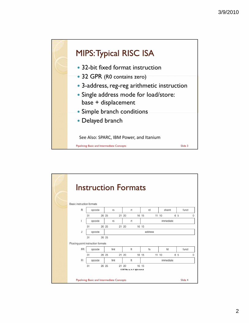
MIPS: Typical RISC ISAMIPS: Typical RISC ISA
32-bit fixed format instruction 32 GPR (R0 c ntains er ) 32 GPR (R0 contains zero)
3-address, reg-reg arithmetic instruction Single address mode for load/store:
base + displacement Simple branch conditionsSimple branch conditions Delayed branch
See Also: SPARC, IBM Power, and Itanium
Slide 3Pipelining: Basic and Intermediate Concepts
Instruction FormatsInstruction Formats
Slide 4Pipelining: Basic and Intermediate Concepts
3/9/2010
3
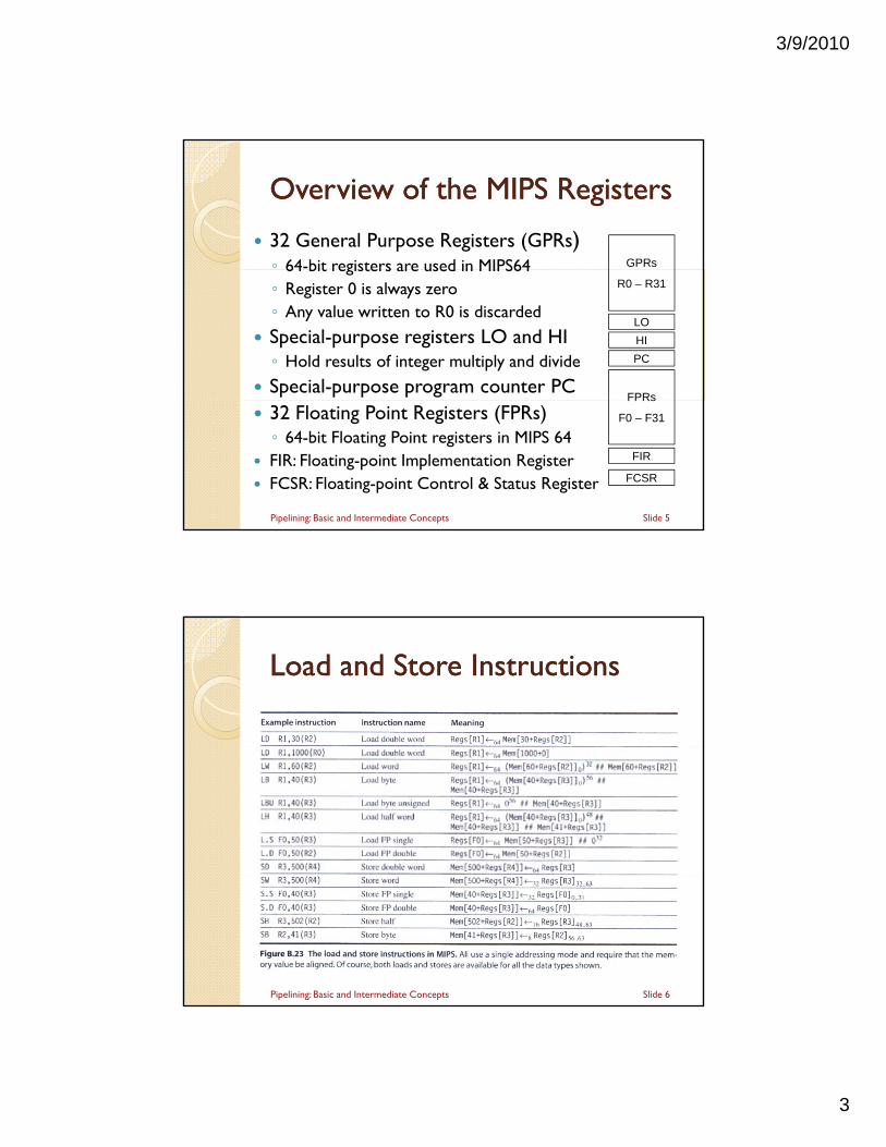
32 General Purpose Registers (GPRs)◦ 64-bit registers are used in MIPS64
Overview of the MIPS RegistersOverview of the MIPS Registers
GPRs64 bit registers are used in MIPS64◦ Register 0 is always zero◦ Any value written to R0 is discarded
Special-purpose registers LO and HI◦ Hold results of integer multiply and divide
Special-purpose program counter PC
R0 – R31
LO
HI
PC
FPRs
32 Floating Point Registers (FPRs)◦ 64-bit Floating Point registers in MIPS 64
FIR: Floating-point Implementation Register FCSR: Floating-point Control & Status Register
FPRs
F0 – F31
FIR
FCSR
Slide 5Pipelining: Basic and Intermediate Concepts
Load and Store InstructionsLoad and Store Instructions
Slide 6Pipelining: Basic and Intermediate Concepts
3/9/2010
4
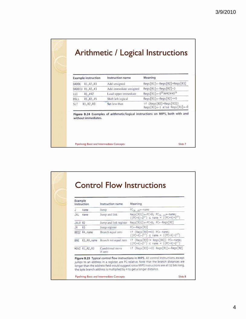
Arithmetic / Logical InstructionsArithmetic / Logical Instructions
Slide 7Pipelining: Basic and Intermediate Concepts
Control Flow InstructionsControl Flow Instructions
Slide 8Pipelining: Basic and Intermediate Concepts
3/9/2010
5
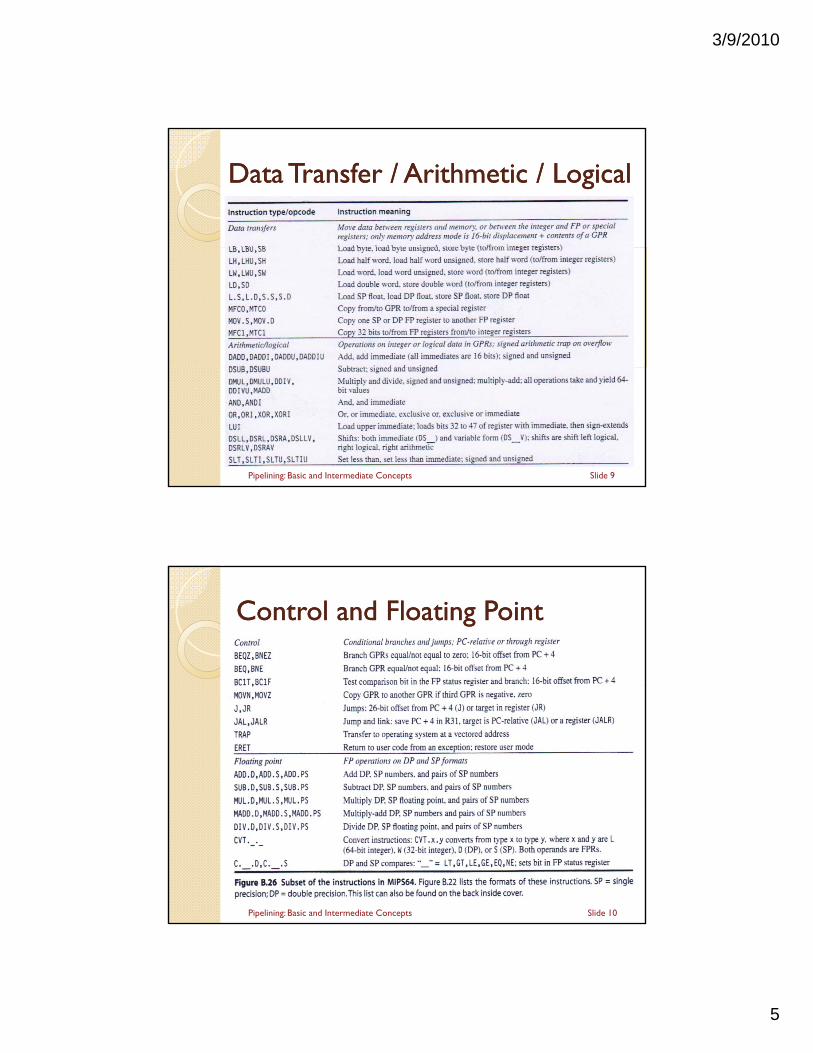
Data Transfer / Arithmetic / LogicalData Transfer / Arithmetic / Logical
Slide 9Pipelining: Basic and Intermediate Concepts
Control and Floating PointControl and Floating Point
Slide 10Pipelining: Basic and Intermediate Concepts
3/9/2010
6
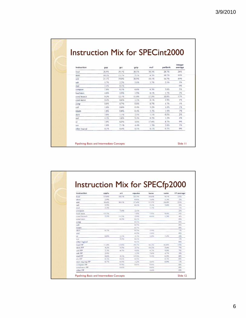
Instruction Mix for SPECintInstruction Mix for SPECint20002000
Slide 11Pipelining: Basic and Intermediate Concepts
Instruction Mix for SPECfpInstruction Mix for SPECfp20002000
Slide 12Pipelining: Basic and Intermediate Concepts
3/9/2010
7
Next:Next:
MIPS – An ISA for Pipelining
5 t i li i 5 stage pipelining Structural Hazards Data Hazards & Forwarding Branch Hazards
H dli E ti Handling Exceptions Handling Multicycle Operations
Slide 13Pipelining: Basic and Intermediate Concepts
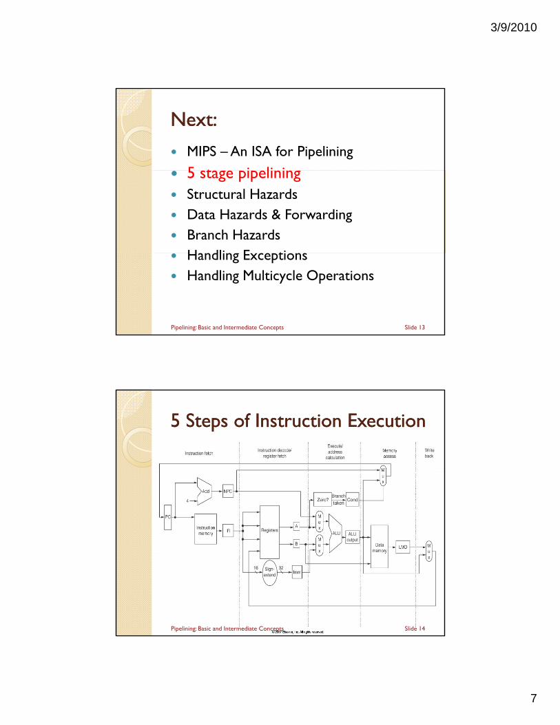
5 5 Steps of Instruction ExecutionSteps of Instruction Execution
Slide 14Pipelining: Basic and Intermediate Concepts
3/9/2010
8
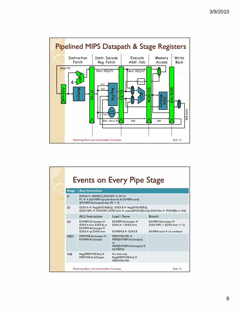
Pipelined MIPS Pipelined MIPS DatapathDatapath & Stage Registers& Stage RegistersMemoryAccess
WriteBack
InstructionFetch
Instr. DecodeReg. Fetch
ExecuteAddr. Calc
Next SEQ PC Next SEQ PCNext PC M
U
ALU
Mem
ory
Reg File
MU
XM
UX
Data
Mem
ory
MU
X
Zero?
IF/ID
ID/EX
MEM
/WB
EX/M
EM
4
Adder
Address
RS1
RS2
X
SignExtend
RW = Rd or Rt RW RW WB
Dat
a
Imm
Slide 15Pipelining: Basic and Intermediate Concepts
Events on Every Pipe StageEvents on Every Pipe StageStage Any Instruction
IF IF/ID.IR MEM[PC]; IF/ID.NPC PC+4PC if ((EX/MEM.opcode=branch) & EX/MEM.cond){ } { }{EX/MEM.ALUoutput} else {PC + 4}
ID ID/EX.A Regs[IF/ID.IR[Rs]]; ID/EX.B Regs[IF/ID.IR[Rt]]ID/EX.NPC IF/ID.NPC; ID/EX.Imm extend(IF/ID.IR[Imm]); ID/EX.Rw IF/ID.IR[Rt or Rd]
ALU Instruction Load / Store Branch
EX EX/MEM.ALUoutputID/EX.A func ID/EX.B, orEX/MEM.ALUoutputID/EX.A op ID/EX.Imm
EX/MEM.ALUoutputID/EX.A + ID/EX.Imm
EX/MEM.B ID/EX.B
EX/MEM.ALUoutputID/EX.NPC + (ID/EX.Imm << 2)
EX/MEM.cond br condition
MEM MEM/WB.ALUoutput MEM/WB.LMD
Slide 16
MEM MEM/WB.ALUoutputEX/MEM.ALUoutput
MEM/WB.LMD MEM[EX/MEM.ALUoutput]orMEM[EX/MEM.ALUoutput]EX/MEM.B
WB Regs[MEM/WB.Rw] MEM/WB.ALUOutput
For load only:Regs[MEM/WB.Rw] MEM/WB.LMD
Pipelining: Basic and Intermediate Concepts
3/9/2010
9
Pipelined ControlPipelined Control Control signals derived from instruction opcode Control signals are pipelined just like datag p p j
Slide 17Pipelining: Basic and Intermediate Concepts
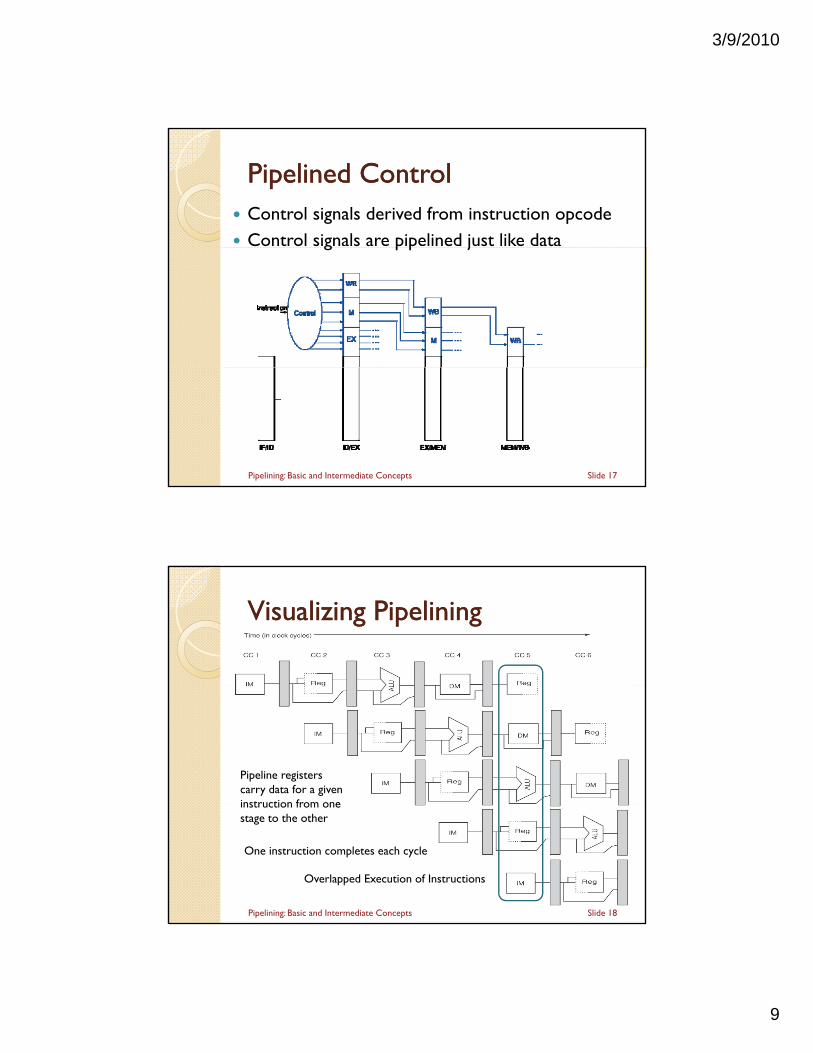
Visualizing PipeliningVisualizing Pipelining
Pipeline registers carry data for a given instruction from one instruction from one stage to the other
Overlapped Execution of Instructions
Slide 18
One instruction completes each cycle
Pipelining: Basic and Intermediate Concepts
3/9/2010
10
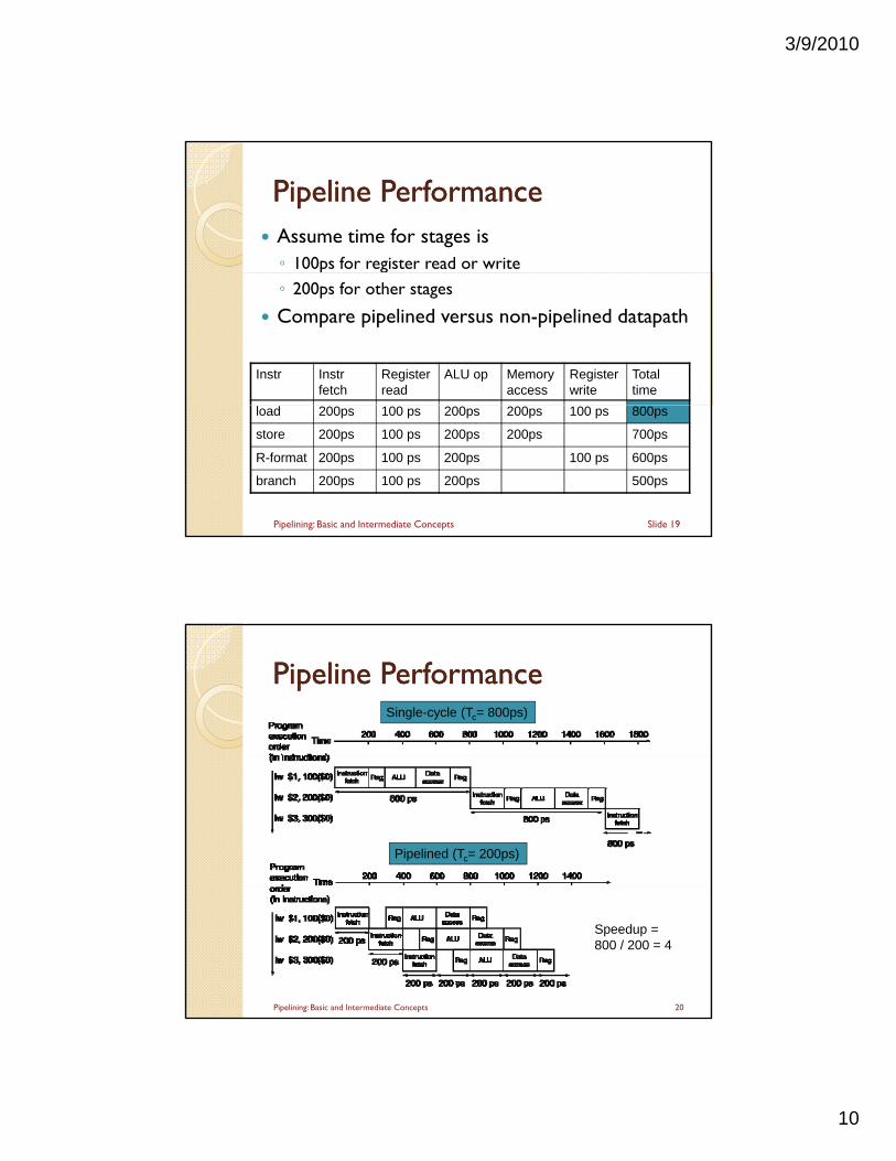
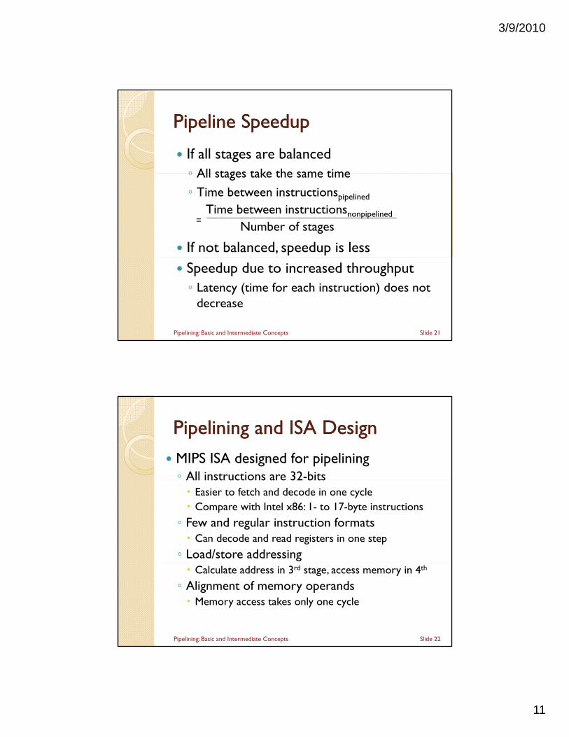
Pipeline PerformancePipeline Performance Assume time for stages is◦ 100ps for register read or write
◦ 200ps for other stages
Compare pipelined versus non-pipelined datapath
Instr Instr fetch
Register read
ALU op Memory access
Register write
Total time
load 200ps 100 ps 200ps 200ps 100 ps 800ps
store 200ps 100 ps 200ps 200ps 700ps
R-format 200ps 100 ps 200ps 100 ps 600ps
branch 200ps 100 ps 200ps 500ps
Slide 19Pipelining: Basic and Intermediate Concepts
Pipeline PerformancePipeline PerformanceSingle-cycle (Tc= 800ps)
Pipelined (Tc= 200ps)
Speedup = 800 / 200 = 4
20Pipelining: Basic and Intermediate Concepts
3/9/2010
11
Pipeline SpeedupPipeline Speedup
If all stages are balanced◦ All stages take the same time◦ All stages take the same time◦ Time between instructionspipelined
Time between instructionsnonpipelined
Number of stages
If not balanced, speedup is less
=
Speedup due to increased throughput◦ Latency (time for each instruction) does not
decrease
Slide 21Pipelining: Basic and Intermediate Concepts
Pipelining and ISA DesignPipelining and ISA Design
MIPS ISA designed for pipelining◦ All instructions are 32-bitsAll instructions are 32 bits Easier to fetch and decode in one cycle Compare with Intel x86: 1- to 17-byte instructions
◦ Few and regular instruction formats Can decode and read registers in one step
◦ Load/store addressing Calculate address in 3rd stage, access memory in 4th
◦ Alignment of memory operands Memory access takes only one cycle
Slide 22Pipelining: Basic and Intermediate Concepts
3/9/2010
12
Pipelining is not quite that easy!Pipelining is not quite that easy!• Limits to pipelining: Hazards prevent
next instruction from executing during g gits designated clock cycleStructural hazards: HW cannot allow two
instructions to use same resource during same cycle
Data hazards: Instruction depends on result of i i i ill i h i liprior instruction still in the pipeline
Control hazards: Caused by delay between the fetching of instructions and decisions about changes in control flow (branches and jumps)
Slide 23Pipelining: Basic and Intermediate Concepts
Next:Next:
MIPS – An ISA for Pipelining 5 stage pipelining 5 stage pipelining
Structural Hazards Data Hazards & Forwarding Branch Hazards
H dli E ti Handling Exceptions Handling Multicycle Operations
Slide 24Pipelining: Basic and Intermediate Concepts
3/9/2010
13
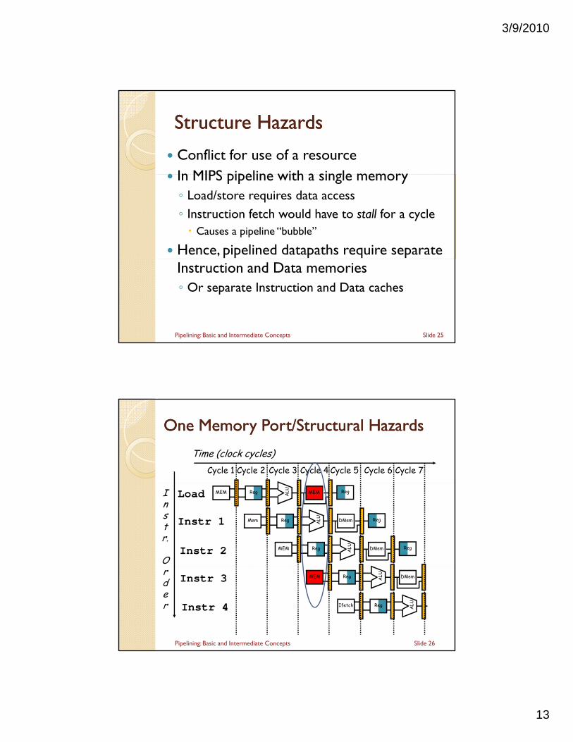
Structure HazardsStructure Hazards
Conflict for use of a resource In MIPS pipeline with a single memory In MIPS pipeline with a single memory◦ Load/store requires data access◦ Instruction fetch would have to stall for a cycle Causes a pipeline “bubble”
Hence, pipelined datapaths require separate Instruction and Data memories◦ Or separate Instruction and Data caches
Slide 25Pipelining: Basic and Intermediate Concepts
One Memory Port/Structural HazardsOne Memory Port/Structural Hazards
Time (clock cycles)Cycle 1 Cycle 2 Cycle 3 Cycle 4 Cycle 6 Cycle 7Cycle 5
Instr.
O
Load
Instr 1
Instr 2
Reg ALU MEMMEM Reg
Reg ALU DMemMem Reg
Reg ALU DMemMEM Reg
rder
Instr 3
Instr 4
Reg ALU DMemMEM
Reg ALUIfetch
Slide 26Pipelining: Basic and Intermediate Concepts
3/9/2010
14
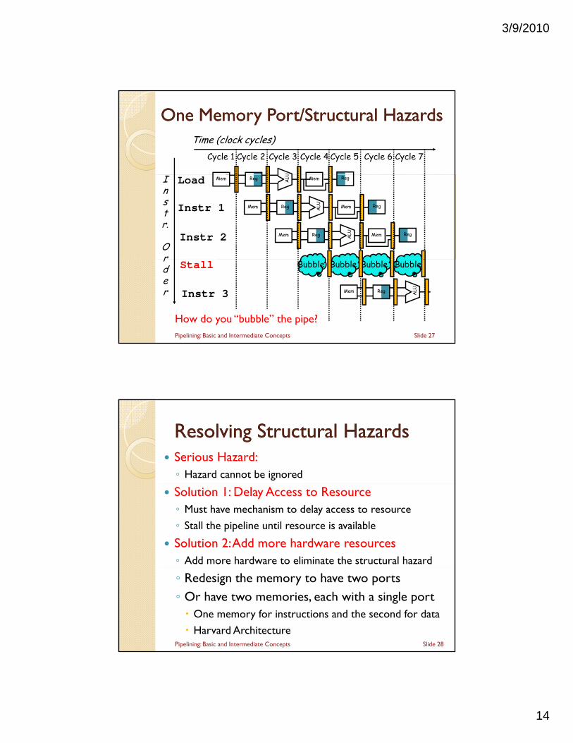
One Memory Port/Structural HazardsOne Memory Port/Structural HazardsTime (clock cycles)
U
Cycle 1 Cycle 2 Cycle 3 Cycle 4 Cycle 6 Cycle 7Cycle 5
Instr.
Or
Load
Instr 1
Instr 2
Reg ALU MemMem Reg
Reg ALU MemMem Reg
Reg ALU MemMem Reg
rder
Stall
Instr 3 Reg ALUMem
Bubble Bubble BubbleBubble
Slide 27
How do you “bubble” the pipe?Pipelining: Basic and Intermediate Concepts
Resolving Structural HazardsResolving Structural Hazards Serious Hazard:◦ Hazard cannot be ignored
Solution 1: Delay Access to Resource◦ Must have mechanism to delay access to resource
◦ Stall the pipeline until resource is available
Solution 2: Add more hardware resources◦ Add more hardware to eliminate the structural hazard
◦ Redesign the memory to have two ports◦ Or have two memories, each with a single port One memory for instructions and the second for data
Harvard ArchitectureSlide 28Pipelining: Basic and Intermediate Concepts
3/9/2010
15
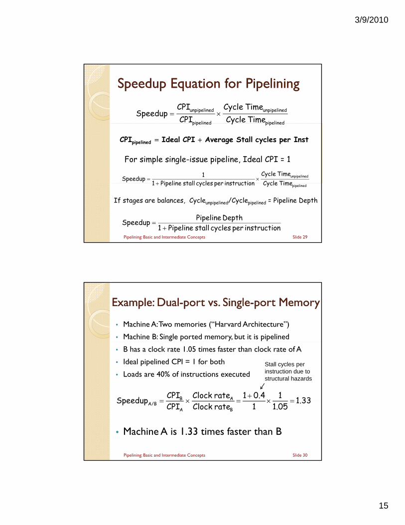
Speedup Equation for PipeliningSpeedup Equation for Pipelining
pipelined
dunpipeline
pipelined
dunpipeline
Time CycleTime Cycle
CPI
CPI Speedup
pipelinedpipelined y
dunpipeline
Time CycleTime Cycle
ninstructio per cycles stall Pipeline 1
1 Speedup
Instper cycles Stall Average CPI Ideal CPIpipelined
For simple single-issue pipeline, Ideal CPI = 1
pipelinedTime Cycleninstructio per cycles stall Pipeline 1
Slide 29
ninstructio per cycles stall Pipeline 1Depth Pipeline Speedup
If stages are balances, Cycleunpipelined/Cyclepipelined = Pipeline Depth
Pipelining: Basic and Intermediate Concepts
Example: DualExample: Dual--port vs. Singleport vs. Single--port Memoryport Memory
• Machine A: Two memories (“Harvard Architecture”)
• Machine B: Single ported memory, but it is pipelined
• B has a clock rate 1.05 times faster than clock rate of A
• Ideal pipelined CPI = 1 for both
• Loads are 40% of instructions executed
1 3310.41rate Clock CPI Speedup AB
Stall cycles per instruction due to structural hazards
• Machine A is 1.33 times faster than B
Slide 30Pipelining: Basic and Intermediate Concepts
1.331.051rate Clock
CPI
SpeedupBA
A/B
3/9/2010
16
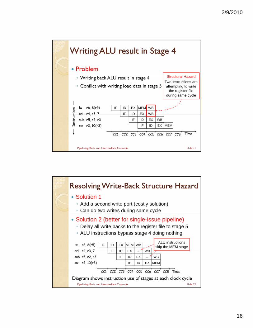
Writing ALU result in Stage Writing ALU result in Stage 44
ProblemW iti b k ALU lt i t 4 Structural Hazard◦ Writing back ALU result in stage 4
◦ Conflict with writing load data in stage 5
WB
WB
IF ID
IF
EX
ID
MEM
EX
lw r6, 8(r5)
ori r4 r3 7tion
sStructural Hazard
Two instructions are attempting to write
the register file during same cycle
WB
EX
ID
WB
EX MEM
IF
TimeCC1 CC4 CC5 CC6 CC7 CC8CC2 CC3
ID
IF
EX
ID
IF
ori r4, r3, 7
sub r5, r2, r3
sw r2, 10(r3)Inst
ruct
Slide 31Pipelining: Basic and Intermediate Concepts
Resolving WriteResolving Write--Back Structure HazardBack Structure Hazard Solution 1◦ Add a second write port (costly solution)◦ Can do two writes during same cycle
WB
WB
IF ID
IF
EX
ID
MEM
EX
lw r6, 8(r5)
ori r4 r3 7
ALU instructions skip the MEM stage
Solution 2 (better for single-issue pipeline)◦ Delay all write backs to the register file to stage 5◦ ALU instructions bypass stage 4 doing nothing
Diagram shows instruction use of stages at each clock cycle
–
EX
ID
WB
–
EX
WB
MEM
IF
TimeCC1 CC4 CC5 CC6 CC7 CC8CC2 CC3
ID
IF
EX
ID
IF
ori r4, r3, 7
sub r5, r2, r3
sw r2, 10(r3)
Slide 32Pipelining: Basic and Intermediate Concepts
3/9/2010
17
Next:Next:
MIPS – An ISA for Pipelining 5 stage pipelining 5 stage pipelining Structural Hazards
Data Hazards & Forwarding Branch Hazards
H dli E ti Handling Exceptions Handling Multicycle Operations
Slide 33Pipelining: Basic and Intermediate Concepts
Data Dependence can cause a data hazard The dependent instructions are close to each other
Data Data HazardsHazards
◦ Pipelined execution changes the order of operand access
Read After Write – RAW Hazard◦ Given two instructions I and J, where I comes before J …
◦ Instruction J should read an operand after it is written by I
◦ Called a data dependence in compiler terminologyp p gy
I: add r1, r2, r3 # r1 is written
J: sub r4, r1, r3 # r1 is read
◦ Hazard occurs when J reads the operand before I writes it
Slide 34Pipelining: Basic and Intermediate Concepts
3/9/2010
18
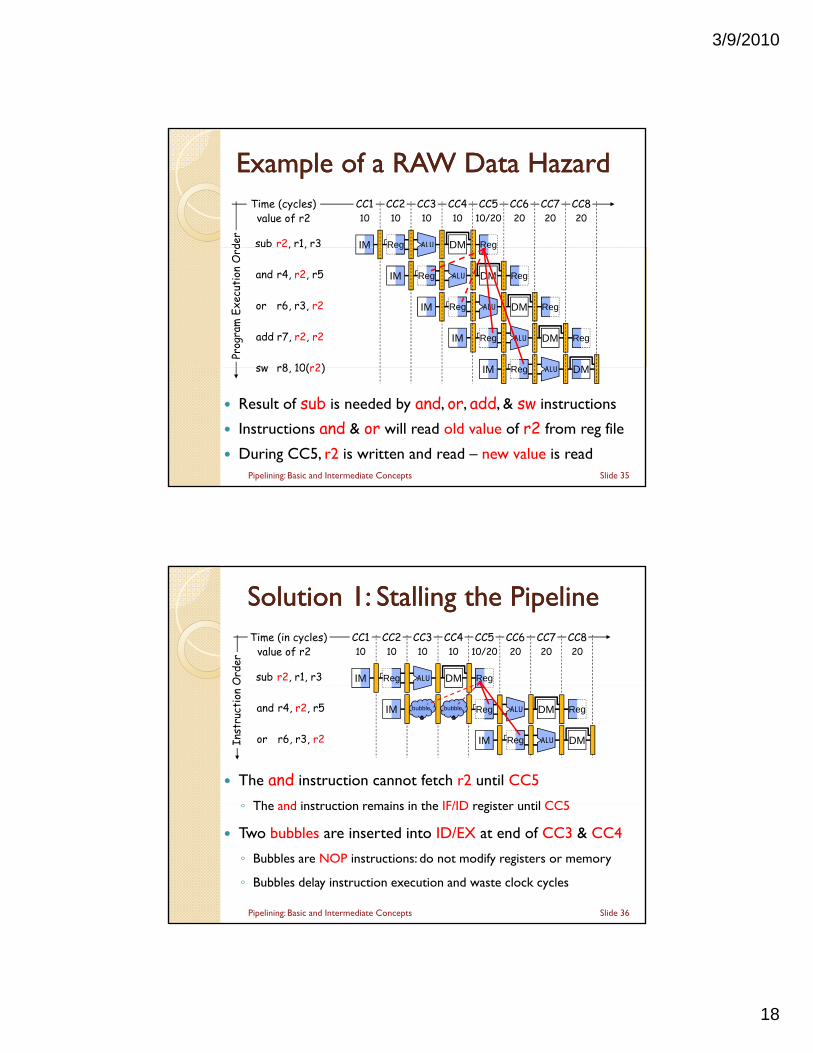
Example of a RAW Data HazardExample of a RAW Data HazardTime (cycles)
der
value of r2
sub r2, r1, r3 IM
CC110
CC2
Reg
10CC3
ALU
10CC4
DM
10CC620
CC720
CC820
CC5
Reg
10/20
Prog
ram
Exe
cuti
on O
rd, , IM
and r4, r2, r5
Reg
IM
or r6, r3, r2
Reg
IM
add r7, r2, r2
DM
ALU
Reg
IM
Reg
DM
ALU
R
Reg
DM
ALU
Reg
DMsw r8 10(r2)
Reg
DM
ALU
Reg
IM
Result of sub is needed by and, or, add, & sw instructions
Instructions and & or will read old value of r2 from reg file
During CC5, r2 is written and read – new value is read
Reg ALU DMsw r8, 10(r2) IM
Slide 35Pipelining: Basic and Intermediate Concepts
Solution Solution 11: Stalling the Pipeline: Stalling the PipelineTime (in cycles)
Ord
er
value of r2CC110
CC210
CC310
CC410
CC620
CC720
CC820
CC510/20
sub r2, r1, r3 IM Reg ALU DM Reg
The and instruction cannot fetch r2 until CC5
◦ The and instruction remains in the IF/ID register until CC5
Inst
ruct
ion
bubbleand r4, r2, r5 IM
or r6, r3, r2 IM Reg DMALU
ALU RegDMRegbubble
◦ The and instruction remains in the IF/ID register until CC5
Two bubbles are inserted into ID/EX at end of CC3 & CC4
◦ Bubbles are NOP instructions: do not modify registers or memory
◦ Bubbles delay instruction execution and waste clock cycles
Slide 36Pipelining: Basic and Intermediate Concepts
3/9/2010
19
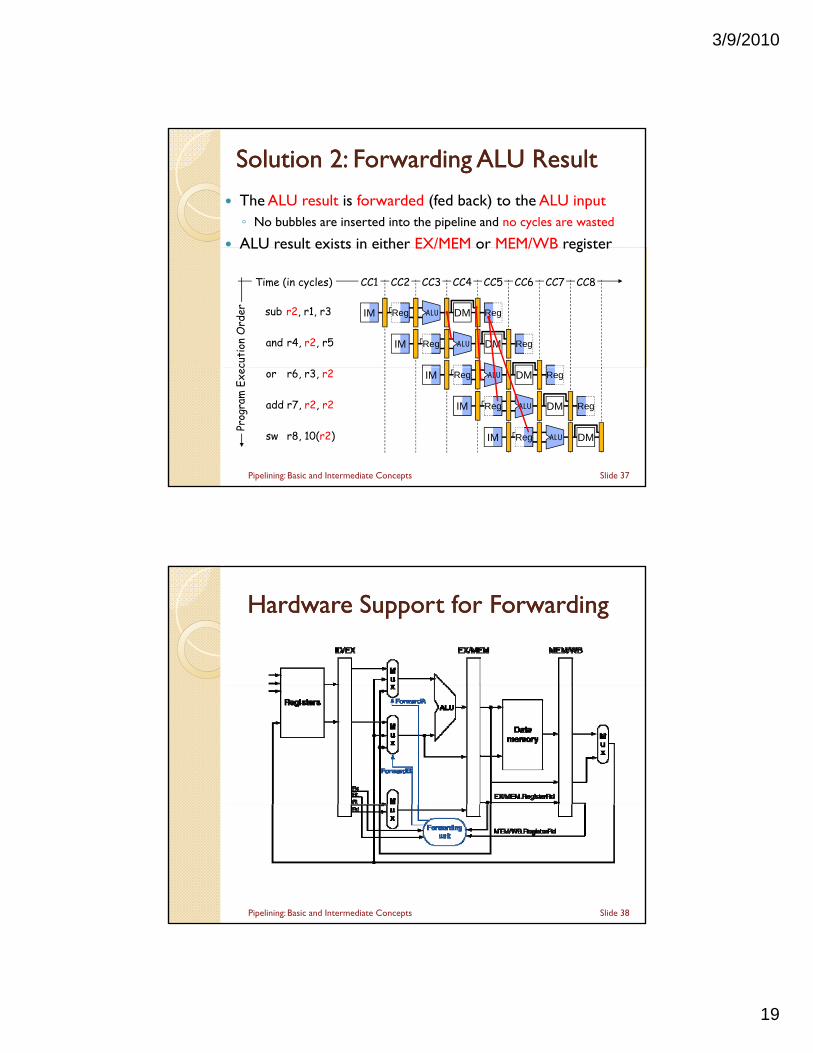
Solution Solution 22: Forwarding ALU Result: Forwarding ALU Result
The ALU result is forwarded (fed back) to the ALU input◦ No bubbles are inserted into the pipeline and no cycles are wasted
ALU result exists in either EX/MEM or MEM/WB registerALU result exists in either EX/MEM or MEM/WB register
Time (in cycles)
cuti
on O
rder
CC2
and r4, r2, r5
Reg
IM
CC3
ALU
Reg
CC6
Reg
CC7 CC8
sub r2, r1, r3 IM
CC1 CC4
DM
ALU
CC5
Reg
DM
Prog
ram
Exe
c
or r6, r3, r2 IM DM
ALU
Reg
Reg
DM
ALU
Reg
DM
add r7, r2, r2
Reg
IM
sw r8, 10(r2)
ALU
Reg
IM
Slide 37Pipelining: Basic and Intermediate Concepts
Hardware Support for ForwardingHardware Support for Forwarding
Slide 38Pipelining: Basic and Intermediate Concepts
3/9/2010
20
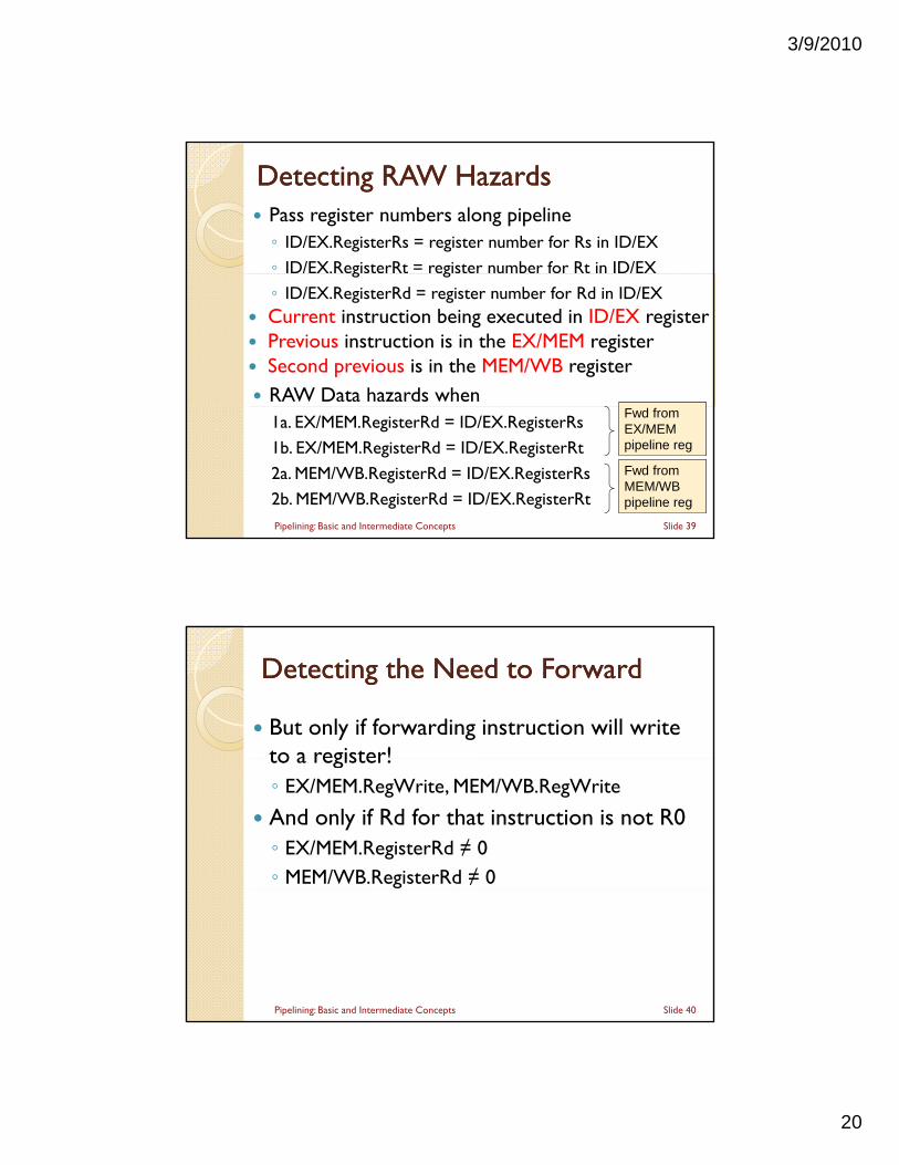
Detecting Detecting RAW HazardsRAW Hazards Pass register numbers along pipeline◦ ID/EX.RegisterRs = register number for Rs in ID/EX
◦ ID/EX.RegisterRt = register number for Rt in ID/EXg g
◦ ID/EX.RegisterRd = register number for Rd in ID/EX Current instruction being executed in ID/EX register Previous instruction is in the EX/MEM register Second previous is in the MEM/WB register RAW Data hazards when
1a. EX/MEM.RegisterRd = ID/EX.RegisterRs
1b. EX/MEM.RegisterRd = ID/EX.RegisterRt
2a. MEM/WB.RegisterRd = ID/EX.RegisterRs
2b. MEM/WB.RegisterRd = ID/EX.RegisterRt
Fwd fromEX/MEMpipeline reg
Fwd fromMEM/WBpipeline reg
Slide 39Pipelining: Basic and Intermediate Concepts
Detecting the Need to ForwardDetecting the Need to Forward
But only if forwarding instruction will write to a register!to a register!◦ EX/MEM.RegWrite, MEM/WB.RegWrite
And only if Rd for that instruction is not R0◦ EX/MEM.RegisterRd ≠ 0◦ MEM/WB.RegisterRd ≠ 0
Slide 40Pipelining: Basic and Intermediate Concepts
3/9/2010
21
Forwarding ConditionsForwarding Conditions Detecting RAW hazard with Previous Instruction◦ if (EX/MEM.RegWrite and (EX/MEM.RegisterRd ≠ 0)
and (EX/MEM.RegisterRd = ID/EX.RegisterRs))F dA 01 (F d f EX/MEM )ForwardA = 01 (Forward from EX/MEM pipe stage)
◦ if (EX/MEM.RegWrite and (EX/MEM.RegisterRd ≠ 0)and (EX/MEM.RegisterRd = ID/EX.RegisterRt))
ForwardB = 01 (Forward from EX/MEM pipe stage)
Detecting RAW hazard with Second Previous◦ if (MEM/WB RegWrite and (MEM/WB RegisterRd ≠ 0)if (MEM/WB.RegWrite and (MEM/WB.RegisterRd ≠ 0)
and (MEM/WB.RegisterRd = ID/EX.RegisterRs))ForwardA = 10 (Forward from MEM/WB pipe stage)
◦ if (MEM/WB.RegWrite and (MEM/WB.RegisterRd ≠ 0)and (MEM/WB.RegisterRd = ID/EX.RegisterRt))
ForwardB = 10 (Forward from MEM/WB pipe stage)Slide 41Pipelining: Basic and Intermediate Concepts
Double Data HazardDouble Data Hazard
Consider the sequence:add r1 r1 r2add r1,r1,r2sub r1,r1,r3and r1,r1,r4
Both hazards occur◦ Want to use the most recent◦ When executing AND, forward result of SUB ForwardA = 01 (from the EX/MEM pipe stage)
Slide 42Pipelining: Basic and Intermediate Concepts
3/9/2010
22
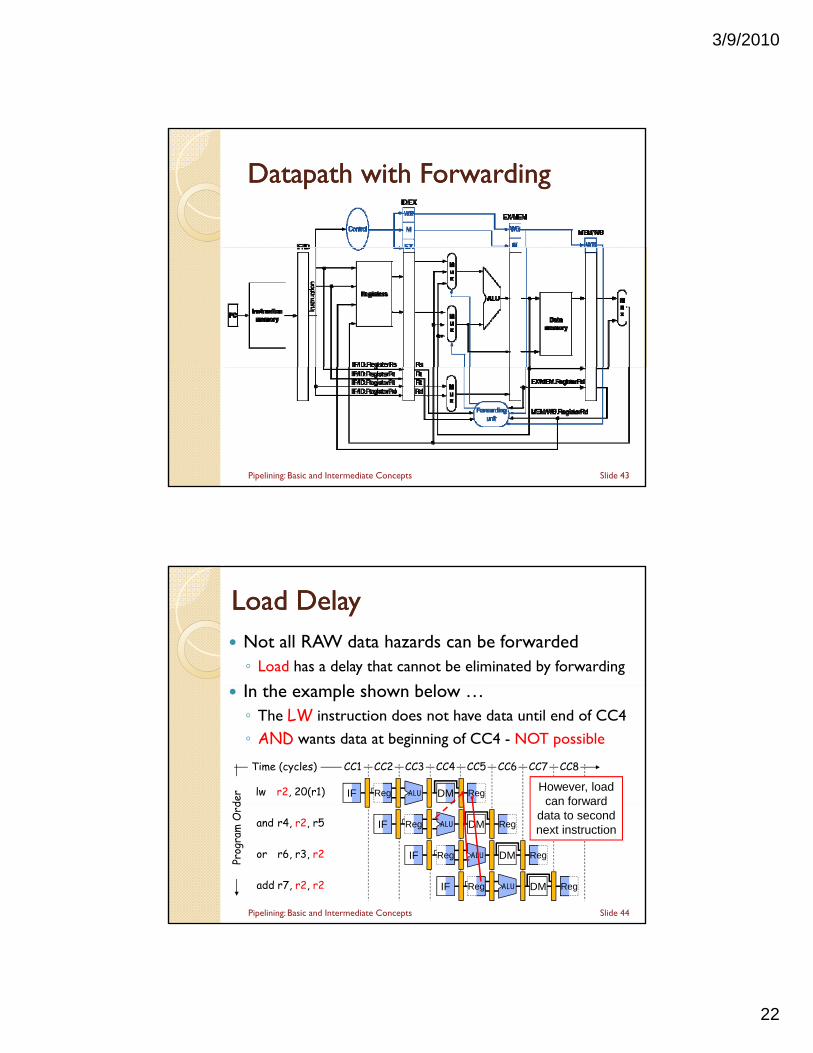
DatapathDatapath with Forwardingwith Forwarding
Slide 43Pipelining: Basic and Intermediate Concepts
Load DelayLoad Delay Not all RAW data hazards can be forwarded◦ Load has a delay that cannot be eliminated by forwarding
I h l h b l In the example shown below …◦ The LW instruction does not have data until end of CC4
◦ AND wants data at beginning of CC4 - NOT possible
DM
Time (cycles)
der
CC2
Reg
CC3
ALU
CC6 CC7 CC8
lw r2, 20(r1) IF
CC1 CC4 CC5
RegHowever, load
can forward
Prog
ram
Ord
and r4, r2, r5 IF
or r6, r3, r2
Reg
IF
Reg
DM
ALU
Reg
DM Regadd r7, r2, r2
ALU
Reg
IF
DM
ALU
Reg
can forward data to second next instruction
Slide 44Pipelining: Basic and Intermediate Concepts
3/9/2010
23
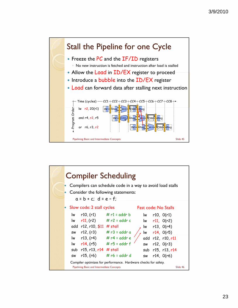
Stall the Pipeline for one CycleStall the Pipeline for one Cycle Freeze the PC and the IF/ID registers◦ No new instruction is fetched and instruction after load is stalled
Allow the Load in ID/EX register to proceed
Time (cycles)
r
CC2 CC3 CC6 CC7 CC8
l 2 20( 1)
CC1 CC4 CC5
Allow the Load in ID/EX register to proceed Introduce a bubble into the ID/EX register Load can forward data after stalling next instruction
bubble
DM
Prog
ram
Ord
er Reg
or r6, r3, r2
ALU
IM
lw r2, 20(r1) IM
Reg
Reg
DM RegALU
and r4, r2, r5 IM Reg RegALU DM
Slide 45Pipelining: Basic and Intermediate Concepts
Compiler SchedulingCompiler Scheduling Compilers can schedule code in a way to avoid load stalls
Consider the following statements:a = b + c; d = e – f;a b c; d e f;
Slow code: 2 stall cycles
lw r10, (r1) # r1 = addr blw r11, (r2) # r2 = addr cadd r12, r10, $11 # stallsw r12, (r3) # r3 = addr a
Fast code: No Stalls
lw r10, 0(r1)lw r11, 0(r2)lw r13, 0(r4)lw r14, 0(r5)
lw r13, (r4) # r4 = addr elw r14, (r5) # r5 = addr fsub r15, r13, r14 # stallsw r15, (r6) # r6 = addr d
add r12, r10, r11sw r12, 0(r3)sub r15, r13, r14sw r14, 0(r6)
Compiler optimizes for performance. Hardware checks for safety.Slide 46Pipelining: Basic and Intermediate Concepts
3/9/2010
24
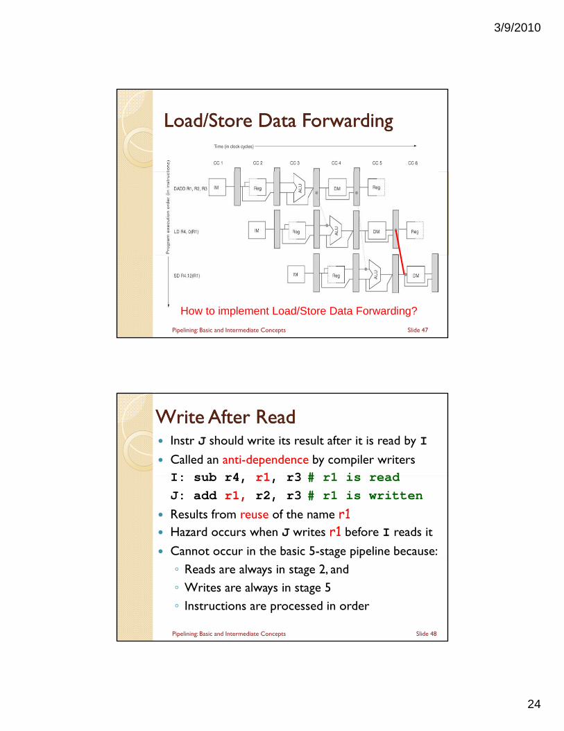
Load/Store Data ForwardingLoad/Store Data Forwarding
Slide 47Pipelining: Basic and Intermediate Concepts
How to implement Load/Store Data Forwarding?
Instr J should write its result after it is read by I
Called an anti-dependence by compiler writersI: sub r4 r1 r3 # r1 is read
Write After Write After ReadRead
I: sub r4, r1, r3 # r1 is read
J: add r1, r2, r3 # r1 is written
Results from reuse of the name r1 Hazard occurs when J writes r1 before I reads it
Cannot occur in the basic 5-stage pipeline because:◦ Reads are always in stage 2, and ◦ Writes are always in stage 5◦ Instructions are processed in order
Slide 48Pipelining: Basic and Intermediate Concepts
3/9/2010
25
Write After Write After WriteWrite Inst J should write its result after I
Called output-dependence in compiler terminologyI b 1 4 3 # 1 i ittI: sub r1, r4, r3 # r1 is written
J: add r1, r2, r3 # r1 is written again
This hazard also results from the reuse of name r1
Hazard when writes occur in the wrong order Can’t happen in our basic 5-stage pipeline because: ◦ All writes are ordered and take place in stage 5
WAR and WAW hazards occur in complex pipelines Notice that Read After Read – RAR is NOT a hazard
Slide 49Pipelining: Basic and Intermediate Concepts
Next:Next:
MIPS – An ISA for Pipelining 5 stage pipelining 5 stage pipelining Structural Hazards Data Hazards & Forwarding
Branch HazardsH dli E ti Handling Exceptions
Handling Multicycle Operations
Slide 50Pipelining: Basic and Intermediate Concepts
3/9/2010
26
Control HazardsControl Hazards Branch instructions can cause great performance loss
Branch instructions need two things:g
◦ Branch Result Taken or Not Taken
◦ Branch Target
PC + 4 If Branch is NOT taken
PC + 4 + 4 × imm If Branch is Taken
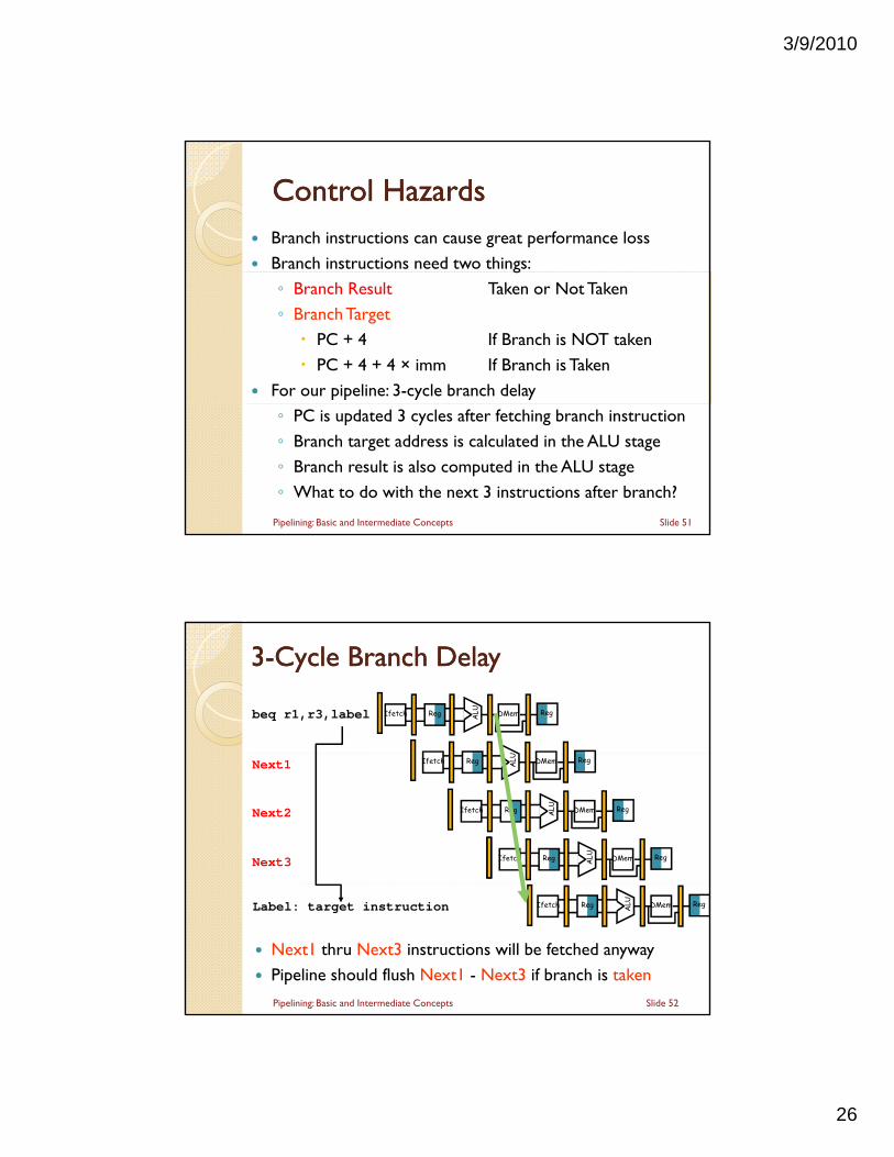
For our pipeline: 3-cycle branch delay
◦ PC is updated 3 cycles after fetching branch instruction
◦ Branch target address is calculated in the ALU stage
◦ Branch result is also computed in the ALU stage
◦ What to do with the next 3 instructions after branch?
Slide 51Pipelining: Basic and Intermediate Concepts
33--Cycle Branch DelayCycle Branch Delay
beq r1,r3,label Reg ALU DMemIfetch Reg
Next1
Next2
Next3
Reg ALU DMemIfetch Reg
Reg ALU DMemIfetch Reg
Reg ALU DMemIfetch Reg
Label: target instruction Reg ALU DMemIfetch Reg
Slide 52Pipelining: Basic and Intermediate Concepts
Next1 thru Next3 instructions will be fetched anyway
Pipeline should flush Next1 - Next3 if branch is taken
3/9/2010
27
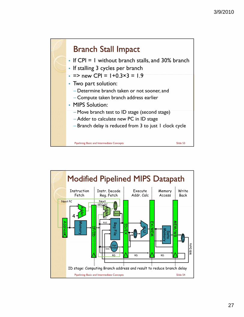
Branch Stall ImpactBranch Stall Impact• If CPI = 1 without branch stalls, and 30% branch• If stalling 3 cycles per branch
> CPI 1+0 3×3 1 9• => new CPI = 1+0.3×3 = 1.9• Two part solution:
– Determine branch taken or not sooner, and– Compute taken branch address earlier
• MIPS Solution:M b h ID ( d ) – Move branch test to ID stage (second stage)
– Adder to calculate new PC in ID stage– Branch delay is reduced from 3 to just 1 clock cycle
Slide 53Pipelining: Basic and Intermediate Concepts
A
Modified Pipelined MIPS Modified Pipelined MIPS DatapathDatapathMemoryAccess
WriteBack
InstructionFetch
Instr. DecodeReg. Fetch
ExecuteAddr. Calc
Next SEQ PC
Next PC MUA
dder
IF/ID
ALU
Mem
ory
Reg File
MU
X
Data
Mem
ory
MU
X
Zero?
MEM
/WB
EX/M
EM
4
Adder
Q
Address
RS1
RS2
UX
ID/EX
SignExtend
RD RD RD WB
Dat
a
ID stage: Computing Branch address and result to reduce branch delay
Imm
Slide 54Pipelining: Basic and Intermediate Concepts
3/9/2010
28
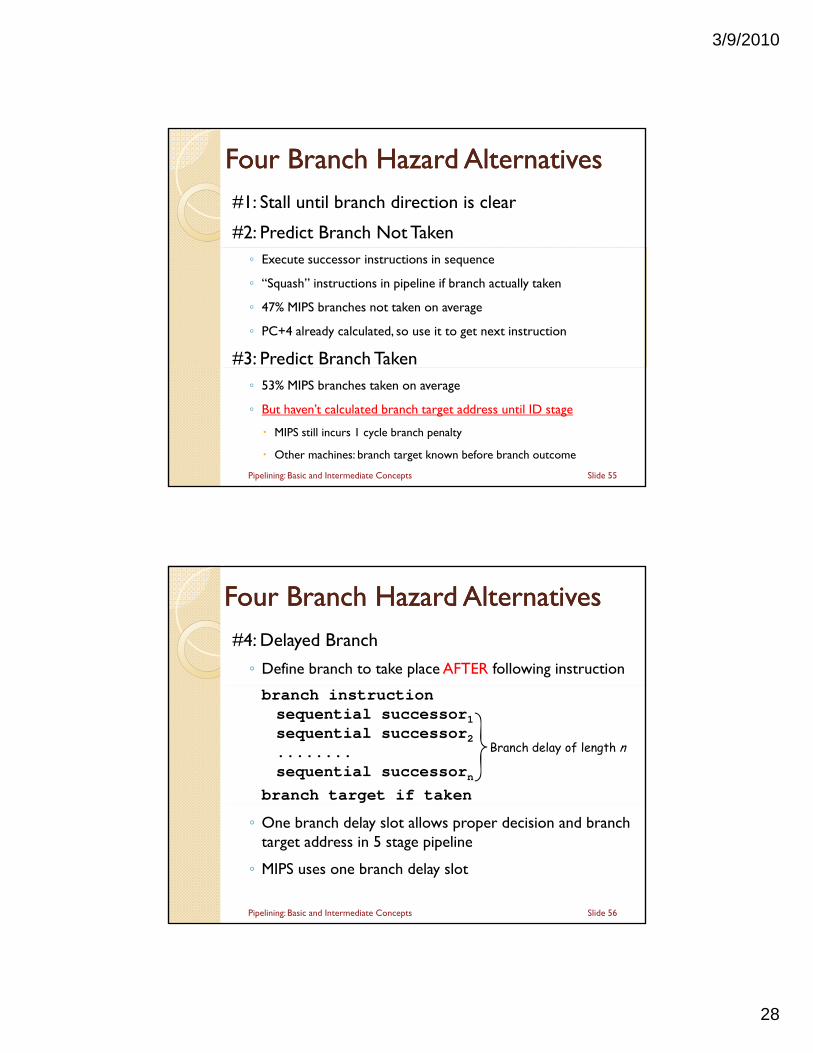
Four Branch Hazard AlternativesFour Branch Hazard Alternatives#1: Stall until branch direction is clear
#2: Predict Branch Not Taken◦ Execute successor instructions in sequence
◦ “Squash” instructions in pipeline if branch actually taken
◦ 47% MIPS branches not taken on average
◦ PC+4 already calculated, so use it to get next instruction
#3: Predict Branch Taken◦ 53% MIPS branches taken on average
◦ But haven’t calculated branch target address until ID stage
MIPS still incurs 1 cycle branch penalty
Other machines: branch target known before branch outcome
Slide 55Pipelining: Basic and Intermediate Concepts
Four Branch Hazard AlternativesFour Branch Hazard Alternatives#4: Delayed Branch
◦ Define branch to take place AFTER following instruction
branch instructionsequential successor1sequential successor2........sequential successorn
branch target if taken
Branch delay of length n
◦ One branch delay slot allows proper decision and branch target address in 5 stage pipeline
◦ MIPS uses one branch delay slot
Slide 56Pipelining: Basic and Intermediate Concepts
3/9/2010
29
Scheduling Branch Delay SlotsScheduling Branch Delay Slots
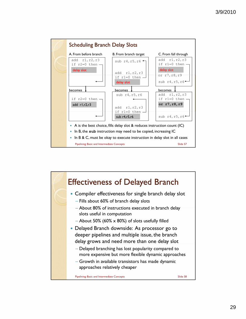
add r1,r2,r3if r2=0 then
delay slot
A. From before branch B. From branch target C. From fall through
add r1,r2,r3
add r1,r2,r3if r1=0 then
delay slot
sub r4,r5,r6
or r7 r8 r9if r1=0 thendelay slot sub r4,r5,r6
becomes
if r2=0 then
add r1,r2,r3
or r7,r8,r9
becomesadd r1,r2,r3if r1=0 then
or r7,r8,r9
becomes
add r1,r2,r3if r1 0 then
sub r4,r5,r6
A is the best choice, fills delay slot & reduces instruction count (IC) In B, the sub instruction may need to be copied, increasing IC
In B & C, must be okay to execute instruction in delay slot in all cases
sub r4,r5,r6
Slide 57Pipelining: Basic and Intermediate Concepts
if r1=0 thensub r4,r5,r6
Effectiveness of Delayed BranchEffectiveness of Delayed Branch Compiler effectiveness for single branch delay slot
– Fills about 60% of branch delay slots
About 80% of instructions executed in branch delay – About 80% of instructions executed in branch delay slots useful in computation
– About 50% (60% x 80%) of slots usefully filled
Delayed Branch downside: As processor go to deeper pipelines and multiple issue, the branch delay grows and need more than one delay sloty g y– Delayed branching has lost popularity compared to
more expensive but more flexible dynamic approaches
– Growth in available transistors has made dynamic approaches relatively cheaper
Slide 58Pipelining: Basic and Intermediate Concepts
3/9/2010
30
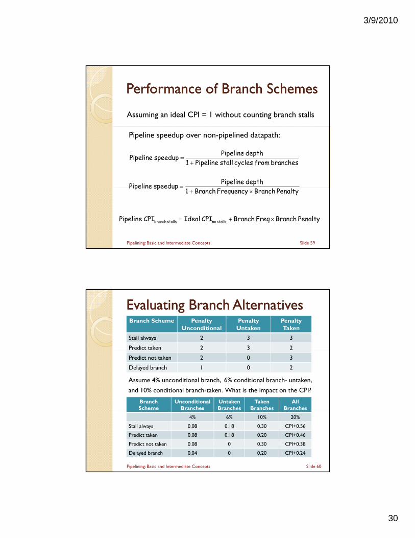
Performance of Branch SchemesPerformance of Branch Schemes
Assuming an ideal CPI = 1 without counting branch stalls
branches from cycles stall Pipeline 1depth Pipeline speedup Pipeline
depth Pipeline speedup Pipeline
Pipeline speedup over non-pipelined datapath:
Slide 59Pipelining: Basic and Intermediate Concepts
Penalty Branch Frequency Branch 1 speedup Pipeline
Penalty Branch Freq Branch CPI Ideal CPI Pipeline stalls nostalls branch
Evaluating Branch AlternativesEvaluating Branch AlternativesBranch Scheme Penalty
UnconditionalPenalty
UntakenPenaltyTaken
Stall always 2 3 3
Predict taken 2 3 2
Assume 4% unconditional branch, 6% conditional branch- untaken,
and 10% conditional branch-taken. What is the impact on the CPI?
Predict not taken 2 0 3
Delayed branch 1 0 2
BranchScheme
UnconditionalBranches
UntakenBranches
TakenBranches
AllBranches
Slide 60Pipelining: Basic and Intermediate Concepts
4% 6% 10% 20%
Stall always 0.08 0.18 0.30 CPI+0.56
Predict taken 0.08 0.18 0.20 CPI+0.46
Predict not taken 0.08 0 0.30 CPI+0.38
Delayed branch 0.04 0 0.20 CPI+0.24
3/9/2010
31
Next:Next:
MIPS – An ISA for Pipelining 5 stage pipelining 5 stage pipelining Structural Hazards Data Hazards & Forwarding Branch Hazards
Handling Exceptions Handling Exceptions Handling Multicycle Operations
Slide 61Pipelining: Basic and Intermediate Concepts
Exceptions and InterruptsExceptions and Interrupts “Unexpected” events requiring change
in flow of control◦ Different ISAs use the terms differently
Exception◦ Arises within the execution of an instruction e.g., undefined opcode, overflow, syscall, …
Interrupt◦ An external I/O device controller is requesting
processor
Exceptions and Interrupts complicate the implementation and control of the pipeline
Slide 62Pipelining: Basic and Intermediate Concepts
3/9/2010
32
Types of ExceptionsTypes of Exceptions I/O device request (hardware interrupt)
Invoking the OS (system call)
Tracing instruction execution
Breakpoint (programmer requested)
Integer arithmetic overflow
Floating Point arithmetic anomaly
Page fault (requested page is not in memory)
Misaligned memory access
Memory protection violation
Undefined instruction
Hardware malfunction and Power failure
Slide 63Pipelining: Basic and Intermediate Concepts
Handling ExceptionsHandling Exceptions
In MIPS, exceptions are managed by a System Control Coprocessor (CP0)p ( )
Save PC of offending (or interrupted) instruction
◦ Exception Program Counter (EPC)
Save indication of the problem
◦ In MIPS: Cause register
Jump to handler at a fixed address
Slide 64Pipelining: Basic and Intermediate Concepts
3/9/2010
33
Handler ActionsHandler Actions
Read cause, and transfer to relevant handler
D i i i d Determine action required
If program can be restarted
◦ Take corrective action
◦ Use EPC to return to program
Otherwise
◦ Terminate program
◦ Report error using EPC, Cause, …
Slide 65Pipelining: Basic and Intermediate Concepts
Alternative ApproachAlternative Approach Vectored Interrupts◦ Handler address determined by the causey
Example:◦ Undefined opcode: C000 0000◦ Overflow: C000 0020◦ …: C000 0040
Instructions either◦ Deal with the interrupt, or◦ Jump to real handler
Slide 66Pipelining: Basic and Intermediate Concepts
3/9/2010
34
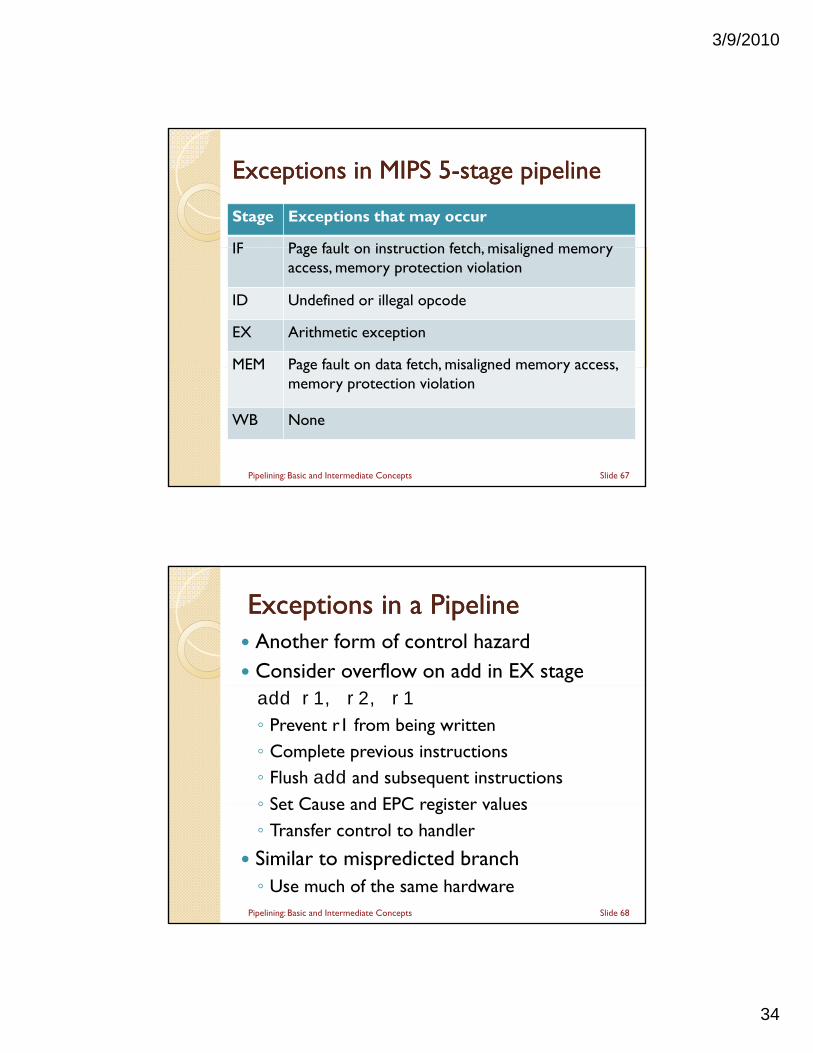
Exceptions in MIPS Exceptions in MIPS 55--stage pipelinestage pipeline
Stage Exceptions that may occur
IF Page fault on instruction fetch misaligned memory IF Page fault on instruction fetch, misaligned memory access, memory protection violation
ID Undefined or illegal opcode
EX Arithmetic exception
MEM Page fault on data fetch, misaligned memory access, MEM Page fault on data fetch, misaligned memory access, memory protection violation
WB None
Slide 67Pipelining: Basic and Intermediate Concepts
Exceptions in a PipelineExceptions in a Pipeline Another form of control hazard Consider overflow on add in EX stageadd r1, r2, r1
◦ Prevent r1 from being written◦ Complete previous instructions◦ Flush add and subsequent instructions◦ Set Cause and EPC register values◦ Set Cause and EPC register values◦ Transfer control to handler
Similar to mispredicted branch◦ Use much of the same hardware
Slide 68Pipelining: Basic and Intermediate Concepts
3/9/2010
35
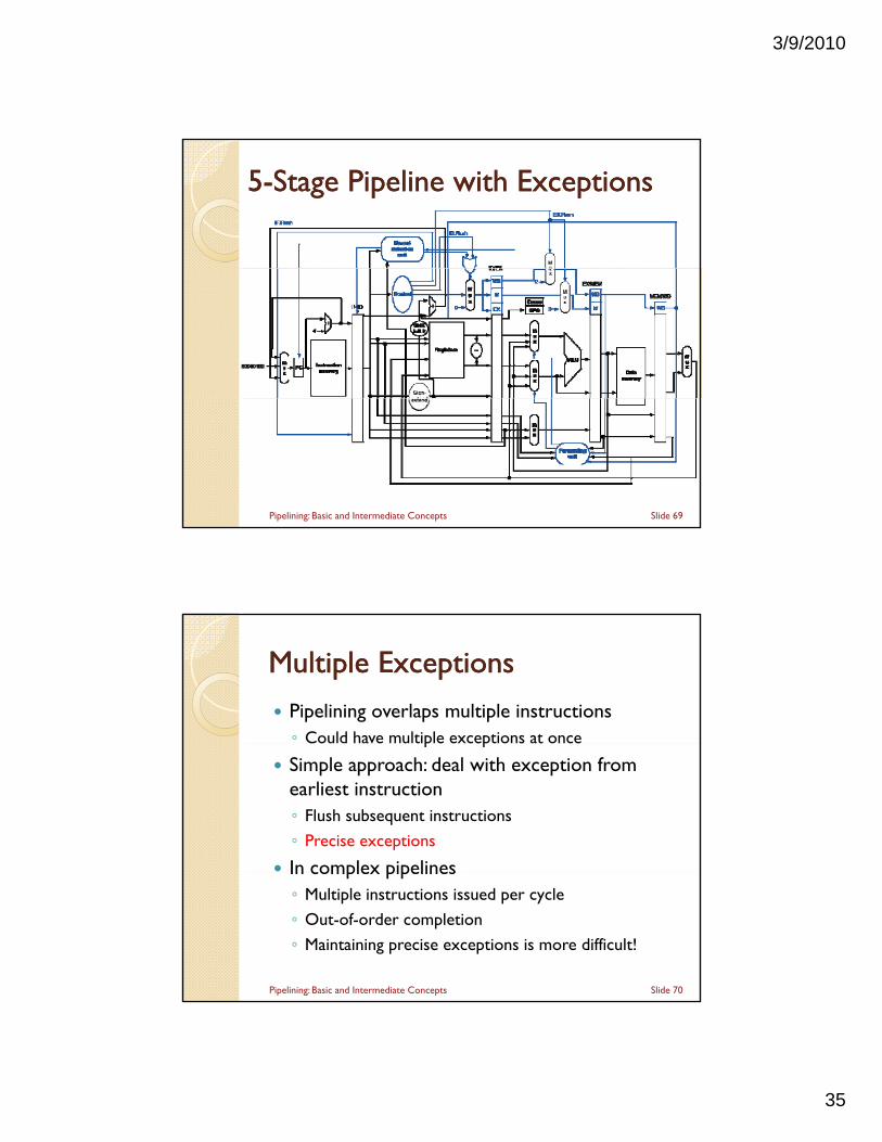
55--Stage Pipeline with ExceptionsStage Pipeline with Exceptions
Slide 69Pipelining: Basic and Intermediate Concepts
Multiple ExceptionsMultiple Exceptions
Pipelining overlaps multiple instructions◦ Could have multiple exceptions at onceCould have multiple exceptions at once
Simple approach: deal with exception from earliest instruction◦ Flush subsequent instructions
◦ Precise exceptions
In complex pipelinesIn complex pipelines◦ Multiple instructions issued per cycle
◦ Out-of-order completion
◦ Maintaining precise exceptions is more difficult!
Slide 70Pipelining: Basic and Intermediate Concepts
3/9/2010
36
Imprecise ExceptionsImprecise Exceptions
Just stop pipeline and save state◦ Including exception cause(s)Including exception cause(s)
Let the handler work out◦ Which instruction(s) had exceptions
◦ Which to complete or flush May require “manual” completion
Simplifies hardware, but more complex handler p , psoftware
Not feasible for complex multiple-issueout-of-order pipelines
Slide 71Pipelining: Basic and Intermediate Concepts
Next:Next:
MIPS – An ISA for Pipelining 5 stage pipelining 5 stage pipelining Structural Hazards Data Hazards & Forwarding Branch Hazards Handling Exceptions Handling Exceptions
Handling Multicycle Operations
Slide 72Pipelining: Basic and Intermediate Concepts
3/9/2010
37
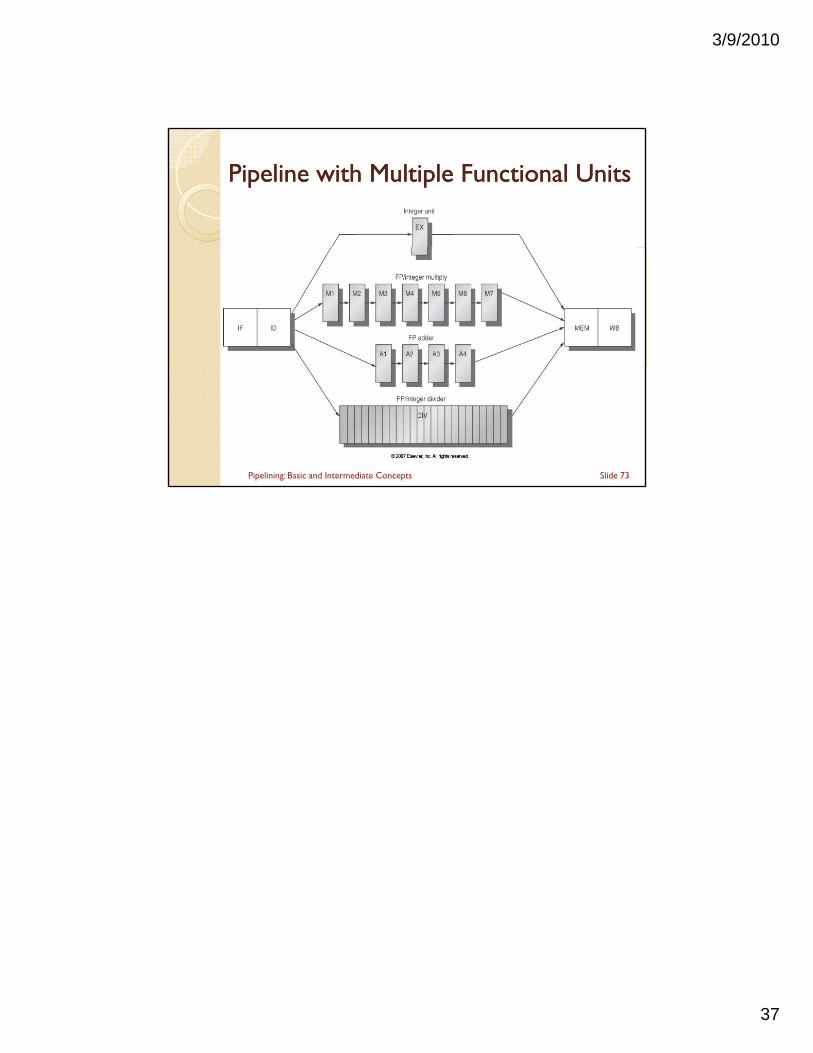
Pipeline with Multiple Functional UnitsPipeline with Multiple Functional Units
Slide 73Pipelining: Basic and Intermediate Concepts


![Pipelining & Parallel Processing - ics.kaist.ac.krics.kaist.ac.kr/ee878_2018f/[EE878]3 Pipelining and Parallel Processing.pdf · Pipelining processing By using pipelining latches](https://img.pdfslide.us/doc/110x75/5d40e26d88c99391748d47fb/pipelining-parallel-processing-icskaistackricskaistackree8782018fee8783.jpg)