Embed Size (px)
Citation preview

©2016 WaveTrue Science + Technologies. All rights reserved.
EMW-C™ Cased Pipe Inspection-Wax Fill Monitoring EMW-I Internal Pipe Inspection Tool (development)
WaveTrue Science + Technologies 504 El Paraiso Rd NE Albuquerque NM 87113
(888) 711-2532/ (212) 625-6622 www.wavetrue.com
Pipeliners Club of Atlanta / NACE

©2016 WaveTrue Science + Technologies. All rights reserved.
Wax-Filled Casing Monitoring
2

©2016 WaveTrue Science + Technologies. All rights reserved.
• Before Fill - Analysis • Identifies existing conditions in casing (location of
spacers, water, shorts, corrosion product) • Provides a baseline for post-fill comparison • Confirms casing length for accurate fill volume
• During Fill - Real Time Analysis • Identifies possible fill problems such as boot leak,
pipe/spacer movement, air / water voids • Tracks % full by volume in real-time
• After Fill - Analysis • Confirms complete fill versus original (empty) baseline • Provides static full-length ‘image’ record of baseline following successful fill
• Long term Periodic Monitoring (Aboveground Re-assessment) • Detect changes over time. • Uses permanent above-grade connections in test station • Compares periodic measurements versus baseline for changes including loss of
wax, water incursion, shorts, and corrosion growth
Long-Range EMW-C Capabilities for Wax Monitoring
3

©2016 WaveTrue Science + Technologies. All rights reserved.
• Connection is made to the carrier and casing (or jacket) using coaxial connectors and cables.
• A pulse generator creates electromagnetic waves (EMW) in the annulus (dielectric).
• The casing and carrier pipe guide the waves, which travel through the annulus and through the dielectric material(s) in the space between.
• Similar to RADAR, the waves are reflected back to the equipment from material changes in the annulus.
• Changes in dielectric material (rust, water, spacers, wax) are seen as variations of amplitude and polarity of reflections.
• Lengthwise distance to reflectors (anomalies) are determined by time of return.
Coaxial Feed Lines
Pulse Generato
r Data Collector
Voltage Divider
Casing
Dielectric (Air, Water, Petrolatum, Polyurethane Insulation, etc.)
Carrier Pipe
EMW-C™ Basic Setup
EMW Direction
3

©2016 WaveTrue Science + Technologies. All rights reserved. 5
• Background: Pipeline Operator found wax in ditch during excavation of adjacent DA inspection leading to concern about integrity of casing seals.
• Problem: Could not visually/physically verify fill volume/condition inside casing.
• Response: EMW-C™ was selected to inspect the casing and assess the condition in the pipe/casing annulus. This was a ‘post-fill’ assessment nearly 40 years after filling.
Case Study – 108 ft. Casing

©2016 WaveTrue Science + Technologies. All rights reserved. 6
Case Study – 108 ft. Casing Detail

©2016 WaveTrue Science + Technologies. All rights reserved. 7
Case Study – 108 ft. Casing Install of Connectors

©2016 WaveTrue Science + Technologies. All rights reserved. 8
Case Study – 108 ft. Casing Connectors Installed

©2016 WaveTrue Science + Technologies. All rights reserved. 9
• EMW-C found several areas of concern: • Unfilled portion at North end of casing. • No wax fill for first 10 feet (10% empty). • Only partial fill from 10-30 feet (20% partial
fill). • Indication of water in casing at South end,
and 40 feet from South end.
• GWUT shot showed unidentified ‘indication’ (change in response) at 10’ and shot ended at 30’.
• Range was limited because of wax.
Case Study – 108 ft. Casing Results

©2016 WaveTrue Science + Technologies. All rights reserved. 10
Case Study – 108 ft. Casing Inspection Results

©2016 WaveTrue Science + Technologies. All rights reserved. 11
Case Study – 108 ft. Casing Comparison

©2016 WaveTrue Science + Technologies. All rights reserved.
= Spacer
Field Shot of 80 Foot 4”/8” Casing
5 12

©2016 WaveTrue Science + Technologies. All rights reserved.
Real-time Monitoring During Wax Fill
13

©2016 WaveTrue Science + Technologies. All rights reserved.
Appendix – EMW-C™
1. PHMSA Guidelines Monitoring 2. Wax Filling Graphics Lab Test
3. EMW comparison to GW
©2016 WaveTrue Science + Technologies. All rights reserved.
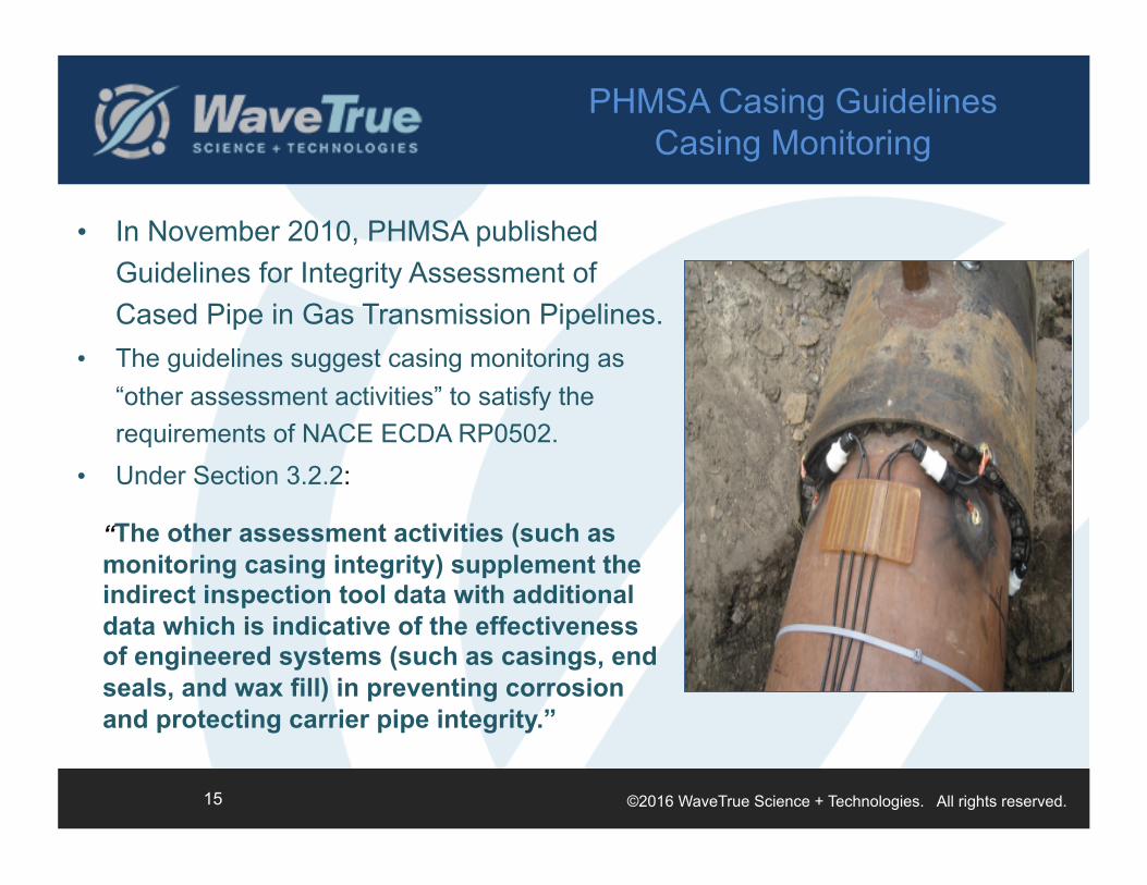
• In November 2010, PHMSA published Guidelines for Integrity Assessment of Cased Pipe in Gas Transmission Pipelines.
• The guidelines suggest casing monitoring as “other assessment activities” to satisfy the requirements of NACE ECDA RP0502.
• Under Section 3.2.2:
PHMSA Casing Guidelines Casing Monitoring
“The other assessment activities (such as monitoring casing integrity) supplement the indirect inspection tool data with additional data which is indicative of the effectiveness of engineered systems (such as casings, end seals, and wax fill) in preventing corrosion and protecting carrier pipe integrity.”
15

©2016 WaveTrue Science + Technologies. All rights reserved.
Casing Monitoring Requirements
“To ensure the continued effectiveness of the casing and fill material at preventing external corrosion: • The fill material must remain in place and continue to encapsulate the carrier pipe. • The level of fill material in the annulus of a casing must be monitored to ensure that the annulus remains effectively filled. Field verification of fill material effectiveness must include verification of casing integrity to assure that fill material is not lost through corroded or damaged casing. • Electrical isolation of the casing from the carrier pipe must also be monitored.”
• Under D.1.2 Guidance for Filled Casings Free of Metallic Shorts and Electrolytic Contacts…
• Long range EMW can verify that the wax remains in place through above ground monitoring and identification of new voids or water incursion.
• Similarly, the level of fill material can be monitored and verified versus original baseline data.
• Electrical isolation is monitored by long range EMW by identification of metallic shorts and electrolytic coupling.
16

©2016 WaveTrue Science + Technologies. All rights reserved.
• Under D.1.1.3 Casing Fill Procedure…
Other Assessment Activities – Casing Monitoring
• Long-range EMW can determine the volume of wax fill immediately after filling to determine if this requirement has been satisfied. WaveTrue can also determine locations along the casing where fill problems may occur.
“Once the fill material level has stabilized, the total volume of fill material pumped into the casing and vents must be compared to the calculated volume. The difference in fill volume should be within 10% of expected.”
17

©2016 WaveTrue Science + Technologies. All rights reserved.
Casing Monitoring Requirements
After the integrity assessment of the carrier pipe and casing has been completed, the operator must periodically monitor casing integrity as described below: • Structural integrity of the casing and end seals (i.e., that the casing pipe and end seals are not leaking) must be monitored. • Fill quantity and fill level must be monitored (i.e., that fill material is not leaking out or melting). • Electrical isolation of the casing from the carrier pipe must also be monitored. The electrical isolation condition of the casing pipe to the carrier pipe must be in the clear or isolated condition. Testing techniques commonly utilized include Panhandle Eastern “B”, Internal Resistance, DCVG, ACVG, Current Attenuation, etc.
• Under D.1.2.5 Periodic Monitoring…
• Long range EMW can verify that the end seals are not leaking through monitoring of the entire annulus for (air) voids, and water incursion.
• Similarly, the level of fill material can be monitored and verified versus original baseline data.
• Electrical isolation is monitored by long range EMW by identification of metallic shorts and electrolytic coupling.
18

©2016 WaveTrue Science + Technologies. All rights reserved.
Casing Monitoring Requirements
Documentation of these quarterly, annual or periodic tests for isolation between the carrier and casing pipe and fill level stability is required. The information must be used in the next reassessment as described in Section 3.
• Under D.1.2.5 Periodic Monitoring…
• Long-range EMW provides documentation of each inspection with graphical representation of the full length of each casing. Consecutive inspections are compared to determine and isolate changes.
19

©2016 WaveTrue Science + Technologies. All rights reserved.
Casing Monitoring Requirements
• Section D of the guidelines also provides monitoring requirements for unfilled casings
D.2.1 Guidance for Monitoring Unfilled Casings Free of Metallic Shorts and Electrolytic Contacts
After the integrity assessment of the carrier pipe and casing has been completed, the operator must periodically monitor casing integrity as described below. • Structural integrity of the casing and end seals (i.e., that the casing pipe and end seals are not leaking) must be monitored. • Electrical isolation of the casing from the carrier pipe must also be monitored. The electrical isolation condition of the casing pipe to the carrier pipe must be in the clear or isolated condition. Testing techniques commonly utilized include Panhandle Eastern “B”, Internal Resistance, DCVG, ACVG, Current Attenuation, etc.
• Just as with filled casings, long-range EMW can be used to perform the same monitoring as required by Section D.2.1 for unfilled casings.
20

©2016 WaveTrue Science + Technologies. All rights reserved. 21
Graphical Demonstration of Capabilities of EMW-C

©2016 WaveTrue Science + Technologies. All rights reserved.
8” Casing – 38 Feet Long / 4” Pipe
• A pipeline / casing with the following specifications: – 38 foot carbon steel, 8” dia. casing – 40 foot carbon steel, 4” dia. carrier pipe – 2” upper and lower vent pipe – 4 PE spacers – Boot seals – Trenton FC #1 fill – Casing windows allowed visual inspection
AI - 5 22

©2016 WaveTrue Science + Technologies. All rights reserved.
BASELINE (Unfilled) Shot 8” Casing – 38 Feet Long / 4” Pipe
4 Plastic Spacers Clearly Identified in Data of Air Filled Casing – Dips in amplitude are a response to variation in dielectric
material (air vs. plastic). AIR
AI - 7 23

©2016 WaveTrue Science + Technologies. All rights reserved.
Partial Fill Realtime Shot 8” Casing – 38 Feet Long / 4” Pipe
• Wax partially fills annulus during fill process. • Plastic spacers start to ‘fade’ as wax (of similar dielectric value) fills
the annulus. • Overall impedance is changing as wax replaces air.
WAX AIR
AI - 8 24

©2016 WaveTrue Science + Technologies. All rights reserved.
Final (Wax Filled) Shot 8” Casing – 38 Feet Long / 4” Pipe
• Plastic spacers faded (as expected). • Expect to see a generally flat line response (typical for totally
filled, homogenous annulus). • This data curves slightly upward, as did the original pre-fill shot,
due to pipe centering. This shot serves as the baseline for future comparisons.
WAX
AI - 9 25

©2016 WaveTrue Science + Technologies. All rights reserved.
Post-Fill Shot with Air Void Added 8” Casing – 38 Feet Long / 4” Pipe
• An air void was created in the wax through an access window at 20 ft by removing 12 oz of wax.
• After another shot, data was subtracted from baseline showing the new air void at 20 ft.
WAX AIR VOID
Air Void
*These shots taken from High Vent End.
AI - 10 26

©2016 WaveTrue Science + Technologies. All rights reserved.
Air Void Water in Void
Post-Fill Shot with Water Void Added 8” Casing – 38 Feet Long / 4” Pipe
• Water (12 oz.) was then added to the void for a second shot. • Data subtracted from baseline shows change at 20 ft. • Note water and air voids produce different responses.
WAX WATER
VOID
*These shots taken from High Vent End.
AI - 11 27

©2016 WaveTrue Science + Technologies. All rights reserved.
Short to Casing
Post-Fill Shot with Short Added 8” Casing – 38 Feet Long / 4” Pipe
• An electrical short was created between casing and pipe at 20 ft. for third shot.
• Data subtracted from baseline clearly shows the change at 20 ft.
WAX SHOR
T
*These shots taken from High Vent End.
AI - 12 28

©2016 WaveTrue Science + Technologies. All rights reserved. 29
Field Condition Cased Pipe
Type/Location Guided Wave Technologies
WaveTrue EMW-C
Direct Short Annulus NA Yes / location
Electrolytic Couple Annulus NA Yes / location
Corrosion Pipe Wall loss only Corrosion products / location in annulus
Corrosion Annulus NA Corrosion products / location in annulus
Water Annulus NA Yes / location
Spacers Annulus NA Yes / location
Wax filled Casing Limited Range Full Range before/during/after fill

©2016 WaveTrue Science + Technologies. All rights reserved.
Over the past several years, the EMW technology has expanded from an external only inspection method to allow for internal inspection. With the EMW-I™, electromagnetic waves are injected into the pipe or tube and ‘fill’ the internal space, producing an interrogation of the entire volume.
• The waves travel through the materials in the space (gas, oil, water, scale, corrosion product, sludge, etc).
• The materials are considered dielectrics to the waves. Part of the wave continues through and another part is reflected back.
• Each dielectric material has a permittivity constant associated with it which changes the impedance of the EMW as it passes through it.
• By analyzing the impedance changes and reflected waves, and comparing them to a signature, materials and their location within the casing can be identified.
EMW-I™
30

©2016 WaveTrue Science + Technologies. All rights reserved.
EMW-I™ Combines Distance, Phase, and
Dielectric Analysis
• By using the rich amount of data provided by EMW reflections, EMW-I™ can interpret various characteristics of features inside the pipe. • Lengthwise distance and feature length
is determined by analysis of time for reflected signals to return.
• By analyzing the impedance of the response, the material makeup of the feature can be inferred (differentiate corrosion from water from scale).
• Through phase interpretation, EMW-I™ is capable of identifying volumetric differences of features. This lends itself to differentiation of voids (i.e. pits) versus the presence of materials (i.e. scale).
31

©2016 WaveTrue Science + Technologies. All rights reserved.
EMW-I™ Applications
• Long-range detection of internal anomalies and corrosion indicators: ‒ Corrosion product and internal pits ‒ Location of cracks ‒ Location of water holdup ‒ Identification of scale or paraffin build-up ‒ Locating blockages and causes of flow reduction ‒ Monitoring for upsets in product flow (ie. slugs)
• Characterization of the magnitude of the anomaly based on data and equivalency models
• Continuous or periodic monitoring to detect changes over time ‒ Permanent connectors may be installed.
32

©2016 WaveTrue Science + Technologies. All rights reserved.
EMW-I™ Other Uses / Key Points
In addition to detection of sludge build-up, EMW-I™ can be used: • To detect and locate anomalies such as wall loss and cracks. (Cracks
significantly disrupt the currents that drive the modes and usually present a large reflection.)
• As a process monitoring system. (In this application, real time monitoring can be used to observe slugs of varying density flowing through the pipeline, e.g. a water slug in a steam pipeline.)
Key points for EMW-I™ are: • A defect or anomaly can be detected even if it is much smaller than the
resolution. • Bends do not pose a problem unless the bend radius is less than about
1.5x the ID of the pipe. • The TE or TM modes launched down the pipe can propagate past an
insulating flange. Although the insulating flange will give a response, information can be obtained past it.
33
©2016 WaveTrue Science + Technologies. All rights reserved.
Summary of Internal Inspection with EMW-I™
• Using EMW-I™, the internal surface and area of a pipe or tube can be inspected at long range for various features including: • Pits, corrosion product, and cracks • Water holdup, scale, sludge, paraffin, and other blockages • Monitoring of upsets, slugs
• The technology can be applied with access to pipe or tube end or via access port such as high-pressure gland.
• May be used for spot inspection or online real-time monitoring.
34

©2016 WaveTrue Science + Technologies. All rights reserved.
Clients Served


![Presenter: Nolan Power Group, LLC - Louisiana Pipeliners of positive plate and grid ... replacement before failure ... Nolan Power Pipeliners presentation.ppt [Compatibility Mode]](https://img.pdfslide.us/doc/110x75/5adcf5647f8b9a9d4d8c76e0/presenter-nolan-power-group-llc-louisiana-pipeliners-of-positive-plate-and-grid.jpg)