Embed Size (px)
Citation preview

PIPE WAYS DESIGNPIPE WAYS DESIGN
PIPE WAYS
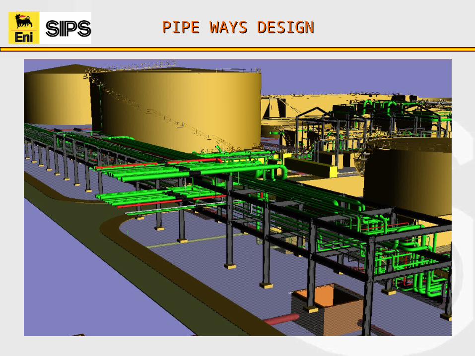
The pipe way carries:
All main process lines connecting distant pieces of equipment. Relief and blow down headers. All lines leaving and entering the plant. Utility lines supplying steam, air, cooling water and inert gas to the
plant. Electrical and instrument cable trays

PIPE WAYS DESIGNPIPE WAYS DESIGN
Pipe rack: Overhead piping supported on steel or concrete

PIPE WAYS DESIGNPIPE WAYS DESIGN
Pipe track: Above ground piping supported on concrete sleepers
PIPE WAYS DESIGNPIPE WAYS DESIGN
Importance of rack in Layout.
In order to arrange the piping within a process unit and interconnecting piping between units, inevitably a number of lines are most conveniently grouped at the same elevation on a common structure. Interconnection piping between process areas and offsite areas
Effective utilization of plot plan area

PIPE WAYS DESIGNPIPE WAYS DESIGN
Configuration:
The pipe rack splits the plant into convenient parts. It takes various shapes such as straight, “L”,”T”,”C”, or even “U”.
This configuration is based on the overall plant arrangement.

PIPE WAYS DESIGNPIPE WAYS DESIGN
“L” configuration “T” configuration

PIPE WAYS DESIGNPIPE WAYS DESIGN
“U” configuration Combination of shapes

PIPE WAYS DESIGNPIPE WAYS DESIGN
An example
PIPE WAYS DESIGNPIPE WAYS DESIGN
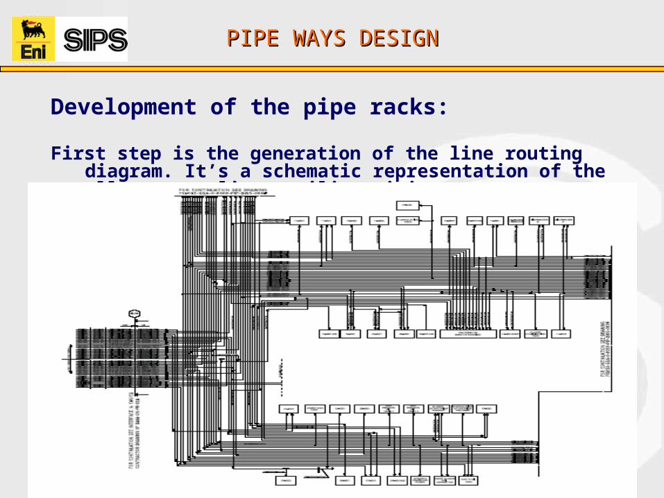
Development of the pipe racks: First step is the generation of the line routing diagram. It’s a schematic
representation of the all process line, utility piping systems.

PIPE WAYS DESIGNPIPE WAYS DESIGN
Inputs required:-
1. Job Specification 2. PFD3. P&ID4. Utility Flow Diagrams 5. Plot plan 6. Interface details7. Anchor points

PIPE WAYS DESIGNPIPE WAYS DESIGN
Inputs required cont….1. Job Specification Battery limit, valving and spade requirements. Isolation valves and relief valves in pipe rack. Secondary access ways Main access roads Railway siding facility Standard to be used for minimum spacing of lines in pipe racks Operating and safety requirements affecting pipe rack and structure design
2. PFD Process flow diagrams show main process scheme and interconnecting process equipment.
3. P&ID Engineering flow diagrams are developed from process flow diagrams and show: Pipe sizes. Pipe classes, and line number. Valves. Manifold. All instrumentation. Equipment and lines requiring services, i.e. water steam, air, nitrogen etc.

PIPE WAYS DESIGNPIPE WAYS DESIGN
Inputs required cont…4. Utility Flow Diagrams Steam Condensate Water Air Gas Nitrogen
5. Plot plan 6. Interface details7. Anchor points

PIPE WAYS DESIGNPIPE WAYS DESIGN
Pipe rack Width:The width of pipe rack is influenced by :
The number of lines Space for future lines. Interdistances b/w lines.
The width of a pipe rack may be calculated using the following method : First estimate number of lines as described. Add up the number of lines up to 18” diameter in the
most dense section of the pipe rack.
The total width in meters (W) will be :

PIPE WAYS DESIGNPIPE WAYS DESIGN
Typical example

PIPE WAYS DESIGNPIPE WAYS DESIGN
Pipe rack Elevation:
Headroom clearance at battery limit. Main road access clearance. Secondary road access clearance. Maintenance equipment access clearance. Process requirements. Safety concepts. Construction feasibility. Project specifications.
PIPE WAYS DESIGNPIPE WAYS DESIGN

PIPE WAYS DESIGNPIPE WAYS DESIGN
Elevation at Pipe rack Intersection:
Where two-tier pipe racks meet, it is essential that elevations of lateral pipe racks shall be between elevations of main pipe rack.

PIPE WAYS DESIGNPIPE WAYS DESIGN
Change in direction in same elevation (Optional) Change in direction in different
elevation (Recomended)
Note: BOP shall be maintained

PIPE WAYS DESIGNPIPE WAYS DESIGN

PIPE WAYS DESIGNPIPE WAYS DESIGN
Column spacing in Pipe Rack:
Following points to be considered: Deflection of pipe at mid-span. Size of the majority lines. Hot lines which span shorter distances than cold lines of the same size and wall thickness Insulated lines; small bore, cold - insulated lines due to weight of insulation must be supported at
relatively short intervals
However normal span of pipe rack sections varies between 4.6M to 6M.In special case ,this may be increased to a maximum of 8M.
PIPE WAYS DESIGNPIPE WAYS DESIGN

PIPE WAYS DESIGNPIPE WAYS DESIGN
Grouping of lines:
1. Process Lines Products lines which run from vessels, exchangers or pump to battery / unit limits Crude or other charge lines entering the unit which run along pipe rack before connecting to process
equipment, furnaces, exchangers, holding drums or booster pumps. Lines interconnecting nozzles on process equipment more than 6M apart (closer spaced equipment
may be directly interconnecting inside piping areas).
2. Relief Headers 3. Utility Headers 4. Small & large bore lines.
PIPE WAYS DESIGNPIPE WAYS DESIGN

PIPE WAYS DESIGNPIPE WAYS DESIGN

PIPE WAYS DESIGNPIPE WAYS DESIGN

PIPE WAYS DESIGNPIPE WAYS DESIGN
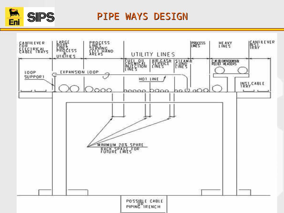
Piping layout on Pipe racks:
1. One Tier Pipe racks
Heavy lines regardless of service are placed over or near the pipe rack columns. Place process and relief lines next to these. Lines serving left hand areas of plant on left, lines serving right hand areas on the right. central pipe rack portion is reserved for utility lines Process lines which interconnect equipment on both sides of the pipe rack should be placed close to
utility lines, and can be on either side of pipe rack, depending upon location of equipment they serve. The position of product lines is influenced by their routing after leaving the unit, right, (left) turning
lines should be on the right (left) hand side of the pipe rack.
PIPE WAYS DESIGNPIPE WAYS DESIGN

PIPE WAYS DESIGNPIPE WAYS DESIGN
Piping layout on Pipe racks:2. Two Tier Pipe racks Utility lines are placed on the top level and process lines on the bottom level. This is not a rigid rule and
where piping economy dictates certain process lines may be routed on the top level.

PIPE WAYS DESIGNPIPE WAYS DESIGN

PIPE WAYS DESIGNPIPE WAYS DESIGN
Design of the pipe tracks: 1. Pipe track Width Pipe track width may be estimated using the method detailed previously for pipe rack
2. Spacing of Pipe track Sleepers: Depending on line size and substance carried in pipes, (i.e. gas or liquid). On an average minimum span = 3 meters, maximum span = 6 meters
3. Pipe track Elevation : Pipe track elevation is set by maintenance access to piping items located underneath the pipe track,
i.e. drains and steam traps. Minimum of 300mm,can be even 500mm.
4. Line Location Line location with reference to bore and weight is unnecessary, as all pipes are supported on
sleepers which rest directly on the ground All lines interconnecting process equipment and/or storage tanks located on left-hand side of pipe
track are placed to the left-hand side. Similarly, all lines interconnecting equipment located on right-hand side of pipe track are placed to
the right of pipe track. Lines interconnecting equipment located on either side of pipe track are placed near the center of
pipe track.

PIPE WAYS DESIGNPIPE WAYS DESIGN
Design of the pipe tracks cont…
5. Line Spacing 6. Road Crossings 7. Access Ways 8. Valves 9. Expansion Loops

SAFETY CONCEPTSSAFETY CONCEPTS
Safety concepts:
Heat radiation factors. Thermal radiation from the line/equipments should not affect the personnel
involved in operations. Equipments (like furnace, flare stack etc) shall be located down stream of the
prevailing wind direction.
Escape ways. Dead ends must be considered max of 7M. Max travel distance to a ladder/stair on a working platform must be 25M. Intermediate platform on the vertical ladder must be at 6M interval. primary & sec escape route to be considered. All main escape routes must be directed towards the road.
Clearances. Head room must be considered a min of 2.2M.
SAFETY CONCEPTSSAFETY CONCEPTS
Safety concepts cont….
Ergonomics & human factors. To prevent human errors and/or its consequences (reliability). To protect the users’ safety & health (integrity) Other Benifits: 1.To enhance productivity by human performance improvements (efficiency). 2.To enforce ease & comfort of operations (usability).
Fire fighting. Plant fire fighting facilities to be designed in such way that all the fire prone
equipments & also the plant area fire can be covered at any point of time. Care should be taken care for the movement of emergency fire tender inside the
plant.
Environment & Pollution factors. Harmful gases to be burnt at higher elevation (flare stack height) Care should be taken care for soil, air & water pollution